design and implementation of urban vehicle positioning...
TRANSCRIPT

Design and Implementation of Urban Vehicle PositioningSystem Based on RFID, GPS and LBS
Cong Qian1,2, He Xu1,2(✉), Peng Li1,2, and Yizhuo Wang3
1 School of Computer Science, Nanjing University of Posts and Telecommunications,Nanjing, China
[email protected], {xuhe,lipeng}@njupt.edu.cn2 Jiangsu High Technology Research Key Laboratory for Wireless Sensor Networks,
Nanjing, China3 Bell Honors School, Nanjing University of Posts and Telecommunications, Nanjing, China
Abstract. In order to monitor the mobile vehicles efficiently and judge thecongestion status under complex condition of road and traffic, Radio frequencyidentification (RFID) technology is used to realize the dynamic identification andinformation exchange of the vehicles together with using the advantage of tech‐nologies of Global Positioning System (GPS) and Location Based Service (LBS)to get the precise position of vehicle. LBS technology is used to realize the func‐tion of showing the congestion status under complex condition of road and traffic,and the status of the vehicle can be shown to users by electronic map on website.The model of vehicle monitoring is designed and the system is implemented andtested on the basis of combination of RFID, GPS and LBS, which can be of greatsignificance to the information construction of traffic detection.
1 Introduction
With the rapid development of the country’s economic construction, the city scale andpopulation extends increasingly, together with the contradiction of people, vehicle androad. The problems of the management of the road traffic caused by the urbanizationand motorization become increasingly serious [1]. The traffic is almost paralyzed aroundthe holidays, when the issue of traffic is very obvious. Usually, government gives priorityto the development of urban public transport as to improve urban residential environ‐ment, construct a harmony society and promote the sustainable development of cities.Strengthening the safety supervision of public transport and vehicle routing could reducecongestion and security risks as well as to promote the development of intelligent trans‐portation systems.
As we all knows, the routes of urban public transport are fixed, so they are monitorednot to select the best route but use Global Positioning System (GPS) to track their real-time position to be arranged conveniently to facilitate passengers and improve theutilization rate of the vehicle. This goals require the application of Radio frequencyidentification technology (RFID) systems. In order to provide greater convenience forpassengers and vehicle schedule in monitoring, we can set up RFID monitoring points
© Springer International Publishing AG 2018L. Barolli and O. Terzo (eds.), Complex, Intelligent, and Software Intensive Systems,Advances in Intelligent Systems and Computing 611, DOI 10.1007/978-3-319-61566-0_55

at key positions such as stations, platforms, tunnel, bridge, etc. to realize the dynamicidentification of vehicles and toll collection making up for the weak signal of GPS inthese key points which lead to the inaccurate positioning [2]. The Singapore bus (SBS)assemble the on-board computer and the GPS locator on each bus, and each platform isequipped with a passenger display board. The central control computers of the intelligenttransportation system tracks and monitors every bus at all time, which can monitor thearrival time and even the attendance of every bus. Passengers can view the operation ofthe bus on the passenger display board on the platform to reduce the waiting time andplan their own itinerary better and also can help managers to adjust their departurefrequency better at the same time [3].
RFID is a kind of communication technology, which can identify the specific targetand read the relevant data through the wireless signal identifying the mechanical or no-eye contact between the system and the specific target [4]. RFID component contains atleast three parts: tag, reader and antenna. The complete RFID systems is also equippedwith computer communication network. RFID technology is favored and used widelyby virtue of the advantages of its easy read, rapid identification, large capacity, long lifetime, strong penetration, high security, high positioning accuracy, etc., while other tech‐nologies like bar code cannot match. The development of RFID technology in the trans‐portation area is very fast since the 80s of the last century, which has been widely usedin vehicle management, logistics management, arrival time prediction of transportationvehicle, smart cards, vehicle positioning, etc. In the intelligent transportation system,the technology of RFID automatic identification can accurately draw the vehicle infor‐mation. The GPS receiver gets the real-time vehicle location information through unin‐terrupted 24 h and then displays and analysis the location information on the electricmap through the powerful LBS technology [5]. In this paper, the RFID storage andpositioning function are combined with the GPS technology, and the road traffic condi‐tions are displayed by using LBS technology to control and manage the city’s vehicletraffic conditions.
2 RFID System Architecture
In this paper, the RFID tag is used to identifications of the specific vehicle in the urbanintelligent transportation system. A complete RFID system consists of reader, tag,antenna and communication network [6], which structure is shown in Fig. 1. Comparedwith the conventional traffic data detection, RFID-based systems is more efficient andcost saving. It accelerates the information of traffic detection and has the followingadvantages:
1. Fast read-write and long identification distance
As long as an object pasted with a RFID tag appears in the effective recognitionrange of reader, it can be detected immediately and dynamic identification. In the intel‐ligent transportation system, the readers are arranged in the key intersection and tunnellocation, where the tags exchange information with readers in a non-contact style. The
600 C. Qian et al.

recognition distance can reach dozens or even hundreds of meters, which makes theidentification more reliable and no time delay.
2. High reliability
RFID tag communicates with a reader in a non-contact style, while a car in a highspeed can also correctly be identified. The anti-collision algorithm can be used to achievemulti-target recognition, which can avoid the errors in reading and writing or missedinformation caused by bad communication environment. The tag has a high pollutionresistance, which can be read and written normally even in dusty and dirty environment.
3. High safety
In RFID systems, the RFID tag can be pasted on the car. Because the tag has alarge storage capacity, it can store a lot of information about the vehicle, such as theinformation of driver, the car information and rated passenger capacity, etc. Theinformation of tags can be encrypted to prevent privacy leaks, such as use of PUFencryption algorithm.
The working principle of RFID based vehicle system is: (1) the reader sends theencrypted information through the antenna to the RFID tag pasted in the vehicle; (2) whenthe tag enter into the range of reader work area, the tag gets energy and sends the encodedinformation to the reader through the built-in RF antenna; (3) the RF antenna of readerreceives the carrier signal which is transmitted by the tag, and the effective informationprocessed by the reader will be sent to the computer to complete identification. Thus, theautomatic management can be realized. RFID systems is shown in Fig. 1.
The feasibility of RFID based vehicle system has the following advantages:
Standard: Since the international RFID standard has some regulations, if it is used locally(a city or a province and even a country) is feasible. It’s necessary to consider the issueof the application standards.
Fig. 1. RFID systems
Design and Implementation of Urban Vehicle Positioning System 601

Low cost: In intelligent vehicle system, active tag is used. Although the cost is muchmore expensive than the passive tag, it reads farther and has high security and largestorage. The proportion of RFID cost is very small compared with the cost of vehicle.
Mature technology: Active tags has a very mature technology in security, confidentialityand privacy protection.
In the intelligent vehicle system, the RFID tags can be pasted in the car class or thedashboard, which can be used in the car while driving without parking. The dataprocessing speed of the traffic management system can reach 3000 kbps after testing insome provinces while the vehicle speed can reach 300 km/h. The reader can be directlyinstalled on the platform or the intersection and tunnel with large traffic flow. The datacan be transmitted to the control center through the network to realize the function oftoll collection, speeding monitoring, positioning and so on.
In this system, the main function of RFID is used to dynamically identify the specificinformation of the vehicle for actual position control and monitoring system, and GPS alsoplays a major role. The intelligent equipment in the era has a rapid development, everyonecan easily enjoy the convenience brought by GPS with good applicability. We can easilymonitor the position of the vehicle by using the LBS technology like Baidu Map. But it hasrestriction that GPS is suitable for outdoor areas. GPS will be no signal in the airtight placelike tunnel. The RFID systems can be used to locate the tag accurately in indoor environ‐ment. The RFID system is set up in the airtight place with large traffic flow which canmake up for the lack of GPS. RFID can realize the uninterrupted vehicle tracking andpositioning [7]. The RFID systems are used in the urban traffic networks or highways andother highly monitored places. In many large data processing like position and vehicle, thecloud computing technology can also play a role. Therefore, the collaborative work basedon GPS, LBS and RFID technologies can solve the operation of automatic identification,dynamic monitoring and accurate management of vehicles.
3 Review of Localization Algorithm
As mentioned above, the GPS signal is weak in tunnel and other indoor environment.These places can set up with RFID system. In this paper, we make use of RFID posi‐tioning technology to make up for the disadvantage of GPS in these places, whichimproves the positioning accuracy of the positioning system.
There are many kinds of methods of RFID positioning such as AOA (based on angle),TDOA, RSSI (based on signal intensity), and PDOA (based on phase) etc. [8]. Eachalgorithm has its own characteristics and advantages and disadvantages. We choose twoalgorithms which are more suitable for our system.
1. AOA localization algorithm (based on angle)
The idea of AOA positioning algorithm is measuring the arrival direction of the RFIDsignal from reader through antenna array and then calculate and measure the anglebetween the reader and the tag. The directivity of the single antenna is limited, so at leasttwo antenna arrays is necessary to complete the AOA positioning. The position infor‐mation of tag can be obtained based on the angle and known reference tags. The
602 C. Qian et al.

intersection of signal of RFID tag detected is the location of tag which is also the posi‐tioning of the tag.
The AOA positioning algorithm schematic is shown in Fig. 2.
Fig. 2. Diagram of AOA localization algorithm
The following equations can be obtained from Fig. 2:
⎧⎪⎨⎪⎩
tan𝛼 =y − y1x − x1
;
tan (𝜋 − 𝛽) = tan𝛽 =y − y2x1 − x
;(3.1)
Then the location is obtained to be tested of tag T:
⎧⎪⎨⎪⎩
x =y2 − y1 + x1 tan𝛼 − x2 tan𝛽
tan 𝛼 − tan𝛽;
y =tan 𝛼y2 − tan𝛽y1 + tan𝛽 tan 𝛼(x1 − x2)
tan 𝛼 − tan𝛽;
(3.2)
All in all, the idea of AOA sitioning requires high sensitivity and resolution ofantenna, and additional expensive array with strong direction equipped is necessary, soits positioning accuracy is high, and these costs are fully acceptable relative to the costsand objects of positioning system.
2. PDOA localization algorithm (based on phase)
The idea of PDOA is combined with the discrete spectrum correction technology toextract the phase between the frequency of emission signal and received signal, calcu‐lating the change of the phase and getting the distance between the tag and the readerthrough relevant calculation. Dual frequency or multi frequency can be used to avoidthe influence of phase period ambiguity. That is, the phase difference measured by thedifference frequency signals is transmitted by the reader through the same distance toget the distance to calculate the location of the tag to be positioned. According to theprinciple of passive RFID backscattering, the reader transmits the carrier signal whose
Design and Implementation of Urban Vehicle Positioning System 603

frequency is f, then the passive RFID tag returns a portion of the carrier signal to thereader when the signal is received, thus the reader demodulates the carrier signal of thetag returns and then get the change of signal phaseθbetween the reader and the tag.Assuming that the distance between the tag and the reader is d, the time differencebetween the carrier signal transmitted from the reader and received from the tag is △t,radio waves travels at the speed of light in the air at c: c = 3 ∗ 108 m/s, so we can get:
d =12
cΔt (3.3)
Assuming the phase changes between carrier signal transmitted from the reader andreceived from the tag is θ, then:
𝜃 = 2𝜋fΔt (3.4)
We can draw the following formula:
d =𝜃
4𝜋fc (3.5)
The θ can be expressed as the sum of n (positive integer) cycles and a lack of wholecycle: △θ (in the range of [0–2 PI]), and c = fλ, so:
d =nλ
2+
λΔθ
4𝜋 (3.6)
According to the actual situation, the variable n cannot be solved obviously, thepositioning range is generally a few meters to tens of meters, the range of electromag‐netic waves id wide, the ultra-high frequency RFID band is generally 900 MHz. If thevariable △θ is used to solve the value of d, the phase will appear the error of 2nπ fuzzycondition because the RFID can only output phase between [0–2π]. In order to eliminatethe error, the problem of phase ambiguity can be solved by using the dual frequency [9].That is, the distance between the reader and the tag is constant, assuming the carriersignal from the reader are f1 and f2 respectively, the corresponding phase variation fromthe tag to reader are θ1 and θ2. If the two phase fuzzy circles are equal, only two phasesubtraction can solve the problem of phase ambiguity. According to the followingformula:
𝜃i =4𝜋dfi
c(i = 1, 2) (3.7)
Then we can get:
d =cΔ𝜃
4𝜋Δf(3.8)
Where △θ = θ1 – θ2, △f = f1 – f2.
604 C. Qian et al.

Thus, the distance is obtained. Then the position of the tag is measured by using thethree-trilateral measurement method. The PDOA requires little signal strength, justdemodulates the signal carrier returned by the tag which is tested to measure the phasechanging and to measure the distance. The measurement precision is high, and the costis not high, so the PDOA positioning algorithm has been widely used.
In this paper, because the RFID based vehicle system is set up in the complex envi‐ronment like the bridge, tunnel with large vehicle flow, we can bury the antenna in theground to avoid the influence of environmental disturbance on the work of RFIDsystems.
4 Design of Vehicle Positioning System
Urban intelligent vehicle positioning system is a service system based on modern elec‐tronic information technology. Its prominent feature is the collection, processing, distri‐bution, exchange, analysis and utilization of data as the main aim to provide traceableand a variety of services for traffic participants. In this paper, we design a city intelligentvehicle positioning system based on RFID, GPS and LBS technology, which can realizethe function of monitoring, querying and releasing the dispatched information and quickresponse.
Fig. 3. The model of intelligent transportation system based on GPS, LBS and RFID
Design and Implementation of Urban Vehicle Positioning System 605

The system is divided into five subsystems: vehicle trajectory query, traffic infor‐mation monitoring, speeding detection, toll collection system, vehicle scheduling. Asshown in Fig. 3, the main function of toll collection system is vehicle tagging in thehigh-speed road and tunnel with large traffic flow, dynamic identification of the taginformation equipped with the vehicle, deducting the cost of the corresponding vehiclethrough the tag to identify the status information of the vehicle. The road informationmonitoring and speed detection module is to monitor vehicle using LBS, GPS servicesand associate RFID tags for each vehicle to realize the monitoring and detection ofvehicle, detecting the vehicle speed and warning of over-speeding, determining thevehicle arrival time and location. By using RFID reader to scan the tag in the vehicleand complement with GPS data, it completes the precise positioning of the vehicles. Wecan schedule the vehicles flexibly according to road traffic when the congestion conditionis occurred. Vehicle trajectory query subsystem uses the LBS services to track thetrajectory of the vehicle to achieve the traceability function. The following Fig. 3 showsthe system model.
Intelligent transportation system is a complex and comprehensive system, and wecannot consider it just only a car or a road. The combination of vehicles and roads andthe use of modern computer technology can be efficient and real-time monitoring fortraffic conditions. We present the combination of GPS, LBS and RFID which is acomplex system that can be able to query any vehicle in system about its location,trajectory and condition.
The main process is as the following: RFID tags is pasted with vehicle informationin a vehicle to be monitored, installing a GPS receiver with network function. Then thevehicle receives the GPS signal and transmits the location and speed to the monitoringcenter and data storage center, RFID systems is set to communicate with vehicles in anon-contact style and locate the vehicles. The monitoring center takes advantage of theLBS technology to receive the data and display it on the electric map so as to learn thecity’s road conditions and vehicle information which can be further analyzed and oper‐ated. The LBS technology current has a rapid development. For instance, the Baidu Mapand Gaode Map services have a variety of very strong application Programming Inter‐faces [10], which can be called directly to complete the required functions. In addition,it is necessary to define a powerful data flow interface which enables the system todisplay the real-time location of the vehicle and the traffic condition that the system donot collapse with a lot of real-time data to receive.
5 Implementation and Test
The hardware configuration of RFID reader is the Impinj R420 readers equipped withtwo antennas as shown in Fig. 4, and the two antennas installed relatively. The readerconnects to the center computer through the Ethernet connection cable to communica‐tion. In our realized system, the mobile part of this system takes advantage of the androidsmart phone with network function, calling the Baidu Map SDK to develop and imple‐mentation. It can record the trajectory and location of the vehicle and upload the locationand other data of the vehicle through socket network programming. The development
606 C. Qian et al.
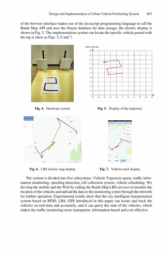
of the browser interface makes use of the Javascript programming language to call theBaidu Map API and uses the Oracle database for data storage, the electric display isshown in Fig. 5. The implementation system can locate the specific vehicle pasted withthe tag is show as Figs. 5, 6 and 7.
Fig. 4. Hardware system Fig. 5. Display of the trajectory
Fig. 6. LBS electric map display Fig. 7. Vehicle track display
The system is divided into five subsystems: Vehicle Trajectory query, traffic infor‐mation monitoring, speeding detection, toll collection system, vehicle scheduling. Wedevelop the mobile and the Web by calling the Baidu Map LBS services to monitor thelocation of the vehicles and upload the data to the monitoring center through the networkfor further operation. Experimental results show that the city intelligent transportationsystem based on RFID, LBS, GPS introduced in this paper can locate and track thevehicles on real-time and accurately, and it can query the state of the vehicles, whichmakes the traffic monitoring more transparent, information-based and cost-effective.
Design and Implementation of Urban Vehicle Positioning System 607

6 Conclusions
In the process of urban traffic regulation, taking advantage of the RFID technology toidentify and interact with vehicle information dynamically to realize the accurate posi‐tioning and ensure the consistency of the information and the GPS information, it cantrack the real-time location of the vehicles, query the data of road condition and vehiclestatus and save the costs of city traffic management. With the support of the powerfulLBS technology, we realize the monitoring and information management of traffic state.It can reduce the time of interaction between the various links to speed up the efficiencyof the vehicle scheduling and emergency detection, and make the information of allaspects of the traffic management to be more transparent and accurate.
Acknowledgments. This work is financially supported by the National Natural ScienceFoundation of P.R. China (No. 61373017, No. 61572260, No. 61572261, No. 61672296, No.61602261), the Natural Science Foundation of Jiangsu Province (No. BK20140886, No.BK20140888), Scientific & Technological Support Project of Jiangsu Province (No. BE2015702,BE2016185, No. BE2016777), Natural Science Key Fund for Colleges and Universities in JiangsuProvince (No. 12KJA520002), China Postdoctoral Science Foundation (No. 2014M551636, No.2014M561696), Jiangsu Planned Projects for Postdoctoral Research Funds (No. 1302090B, No.1401005B), Jiangsu Postgraduate Scientific Research and Innovation Projects (SJLX16_0326),Project of Jiangsu High Technology Research Key Laboratory for Wireless Sensor Networks(WSNLBZY201509), NUPTSF (Grant No. NY214060, No. NY214061) and the STITP projectsof Bell Honors School of NUPT (No. ZD201606 and No. YB201615).
References
1. Toral, S.L., Gregor, D., Vargas, M., et al.: Distributed urban traffic applications based onCORBA event services. Int. J. Space Based Situated Comput. 1(1), 86–97 (2011)
2. Liu, T., Yang, L., Lin, Q., et al.: Anchor-free backscatter positioning for RFID tags with highaccuracy. In: Proceedings of INFOCOM, pp. 379–387 (2014)
3. Dobkinm, D.M.: The RF in RFID: UHF RFID in Practice. Newnes, Waltham (2012)4. Sakurai, S.: Prediction of sales volume based on the RFID data collected from apparel shops.
Int. J. Space Based Situated Comput. 1(2–3), 174–182 (2011)5. Nam, S., Park, M., Kim, K., et al.: A study on the regulations and market of Location Based
Service (LBS). J. Internet Comput. Serv. 15(4), 141–152 (2014)6. Wang, J., Katabi, D.: Dude, where’s my card? RFID positioning that works with multipath
and non-line of sight. ACM SIGCOMM Comput. Commun. Rev. 43(4), 51–62 (2013)7. Beyerle, G., Zus, F.: Open-loop GPS signal tracking at low elevation angles from a ground-
based observation site. Atmos. Meas. Tech. 10(1), 15–34 (2017)8. Gomez-Gil, J., Alonso-Garcia, S., Gómez-Gil, F.J., et al.: A simple method to improve
autonomous GPS positioning for tractors. Sensors 11(6), 5630–5644 (2011)9. Wang, E., Zhao, W., Cai, M.: Research on improving accuracy of GPS positioning based on
particle filter. In: 8th IEEE Conference on Industrial Electronics and Applications (ICIEA),pp. 1167–1171 (2013)
10. Yang, L., Yang, G., Zhang, Q., et al.: Management and analysis platform of radio coveragedata based on Baidu map. In: Fifth International Conference on Instrumentation andMeasurement, Computer, Communication and Control (IMCCC), pp. 369–372 (2015)
608 C. Qian et al.

本文献由“学霸图书馆-文献云下载”收集自网络,仅供学习交流使用。
学霸图书馆(www.xuebalib.com)是一个“整合众多图书馆数据库资源,
提供一站式文献检索和下载服务”的24 小时在线不限IP
图书馆。
图书馆致力于便利、促进学习与科研,提供最强文献下载服务。
图书馆导航:
图书馆首页 文献云下载 图书馆入口 外文数据库大全 疑难文献辅助工具