design and maintenance manual - cannon tech type a single bay manual... · 3. housing parameters...
TRANSCRIPT

Cannon Technologies Ltd Issue 2
Page 1 of 34
O2 UK
Single Bay 2G or 3G Cabinet
Cabinet Type “A” Drawing Number S111800A
Design And
Maintenance Manual
Cannon Technologies Ltd Issue 2
Page 2 of 34
Contents
1. PREFACE ....................................................................................................................................................... 4
1.1 Document History..................................................................................................................................... 4 1.2 Glossary/Abbreviations............................................................................................................................ 4 1.3 References ................................................................................................................................................ 4
2. INTRODUCTION............................................................................................................................................. 5
3. HOUSING PARAMETERS ............................................................................................................................. 5
3.1 Installed Equipment Parameters ............................................................................................................. 5 3.1.1 ACTIVE EQUIPMENT COMPARTMENT LAYOUT........................................................................................... 5 3.1.2 ELECTRICAL SERVICES COMPARTMENT LAYOUT… …………………………………………………………....6
4. ROADSIDE EQUIPMENT HOUSING APPROACH........................................................................................ 6 4.1 Roadside Equipment Housing Dimensions............................................................................................ 6
4.2 Roadside Equipment Housing Mechanical Construction ..................................................................... 7 4.2.1 ROADSIDE EQUIPMENT HOUSING DESIGN................................................................................................ 7 4.2.2 REC METER & MAIN FUSE ..................................................................................................................... 8 4.2.3 FEEDER CABLE ENTRY / ROADSIDE EQUIPMENT HOUSING ROOT SYSTEM .................................................. 8 4.2.4 DOOR LOCKS ....................................................................................................................................... 7 4.2.5 MATERIALS ........................................................................................................................................ 10 4.2.6 FINISH…………………………………………………………………………………………………………..11 4.2.7 VANDAL-PROOFING MEASURES ........................................................................................................... 11
5. ROADSIDE EQUIPMENT HOUSING ACTIVE COMPONENT DESIGN ...................................................... 11
5.1 Climate Control ....................................................................................................................................... 11 5.1.1 THERMAL CHAMBER ........................................................................................................................... 11 5.1.2 ENVIROMENTAL CONTROL & ALARM MODULE (ECM)............................................................................ 13
5.2 AC Consumer Unit .................................................................................................................................. 14 5.3 DC Power Supply.................................................................................................................................... 15
6. INSTALLATION............................................................................................................................................ 15
6.1 Concrete Base Design.............................................................................................................................. 16 6.2 Roadside Equipment Housing Positioning................................................................................................ 17 6.3 Handling.................................................................................................................................................... 17
7. MAINTENANCE............................................................................................................................................ 18 7.1 Preventative Maintenance ........................................................................................................................ 19 7.2 Health and Safety........................................................................................................................................19
8. REPAIR TO DAMAGED PAINTWORK……………………………………………………………………………..19 8.1 Touch-up Repair, Powder Coating Only Damaged…………………………………………….......................19 8.2 Powder Coating Damaged With The Substrate Exposed……………………………………....................... 20
9. APPENDICES…………………………..……………………………………………………………..……………....20-34
1 Installation Instructions for a single Bay 2G/3G BTS Cabinet 2 Environmental Control System Including Electrical Assembly Drawing S111838A Issue 1 3 230-volt AC Distribution Drawing P8811902 4 Test Certificate DC0124 5 Drawing: S111800A (Main Cabinet) 6 Drawing: S111803C (Direct Bury Root) 7 Drawing: S111803B (Root installation instructions) 8 Connection of Battery Back-up System - DC back-up P8811903-2
9 Alarm Mapping

Cannon Technologies Ltd Issue 2
Page 3 of 34
1. O PREFACE
1.1 Document History
Issue Date Author Comments
1
19THAug 04
V. Newton
First Release for acceptance
2 06th Aug N. Perren /
G. Nutt
Updated
1.2 Glossary/Abbreviations
HMC – Heat Management Control System
Hiab – Mechanical (hydraulic) lifting device – usually lorry mounted.
ACM – Alarm Control Module
MCB – Miniature Circuit Breaker
RCD – Residual Current Device
IEE - Institution of Electrical Engineers
ECM - Environmental Control System
REC - Regional Electricity Company
LTE - Line Terminating Equipment
1.3 References
Cannon drawing number S111800A & document No. DC0087
O2UK Drawing No. 2512
O2UK Radio Datasheet 6401

Cannon Technologies Ltd Issue 2
Page 4 of 34
2. INTRODUCTION
The purpose of this document is to explain the Active Equipment Enclosure design and features incorporated to meet the requirements laid out by O2UK
The Roadside Equipment Housing proposed is a development on the StreetWise range of cabinets manufactured by Cannon Technologies Ltd and is an IP55 rated cabinet against BS EN 60529:1992 Degrees of Protection provided by enclosures.
3. HOUSING PARAMETERS
The compartment design of the Active Roadside Equipment Enclosure has been based on the principals defined by O2UK
but with supplementary modifications to comply with
the Summary of Technical Requirements outlined within radio equipment specification.
The roadside equipment housing incorporates an equipment chamber and a separate electrical chamber independently accessed from a single hinged side opening door. The roadside equipment housing incorporates a DC battery back-up system which provides a minimum of 10 minutes DC back-up as the standard option, this is based on the heaviest configuration of 6 x 2G trx or 3 x 3G trx (Nokia).
Early production units were 230V AC operated kit. O2UK’s preference is for DC operated kit.
3.1 Installed Equipment Parameters
The roadside equipment Housing is designed to accommodate the standard and ultimate configurations specified by O2UK
including associated cabling requirements.
The design of the roadside equipment Housing (specified further in this document) account for the physical parameters of O2UK specified equipment deployed in meeting the functionality of these cabinets.
3.1.1 Active Equipment Compartment layout The Nokia equipment housing is positioned within the Thermal Chamber; this is the
environmentally controlled area within the cabinet; fresh filtered ambient air enters the thermal chamber via a filter housing positioned in the front door allowing air to enter the Nokia equipment through the rear door. This air is forced fan circulated via fans internal to the Nokia equipment where it leaves the front door of the equipment at temperature. The main cabinet fans positioned within the roof void draw this warm air vertically expelling it directly back to atmosphere through an IP vent positioned within the rear roof panel of the main cabinet housing.
Fig 1

Cannon Technologies Ltd Issue 2
Page 5 of 34
3.1.2 Electrical Services Compartment layout
Fig 3
Fig 2
Fig 4
This section is designed to accommodate the 230-volt AC supply termination, AC consumer unit and ACM complete with space for optional 3G isolation and connection. On cabinets supplied after April 2006. All wiring and cable colouring complies with IEE regulations to BS EN 60446:2000 and BS EN 60445:2000 Table 51 and Appendix 7 and BS7671:2001 amendment No2 2004.
Fig 2 shows the electrical chamber complete; Fig 3 is a detailed picture of the Environmental control system, the IDC alarm connection module and the consumer unit. Fig 4 shows a close up of the main consumer unit. (See section 5.1.2 and 5.2 for full details)
4. ROADSIDE EQUIPMENT HOUSING APPROACH
The Roadside Equipment Housing is dual skinned and insulated for high heat management incorporating a 2-fan Forced Fan Convection System (FanCell) housed within the fan trays to control the equipment housings internal environment. An additional forced fan unit is installed in the electrical compartment. The total air flow is
2140 m³/hr at 35°C. The air flow for the electrical compartment is 350 m³/hr at 35oC.
The main body of the Roadside Equipment Housing is manufactured from Z600 galvanised steel.
4.1 Roadside Equipment Housing Dimensions
Accommodating the physical layout defined within this document the Roadside Equipment Housing sizing is as follows:
Height: 1800-mm from ground level
Width: 1400-mm
Depth: 730-mm including doors
Weight of cabinet: 341-Kilos ex-works Cannon Technologies Ltd

Cannon Technologies Ltd Issue 2
Page 6 of 34
Weight of Root: 41-Kilos ex-works Cannon Technologies Ltd
4.2 Roadside Equipment Housing Mechanical Construction
4.2.1 Roadside Equipment Housing Design
The Roadside Equipment Housing consists of two separate compartments:
• Active electronic equipment section, accessed through two doors (one front & one right-hand end)
• Electrical Services/AC consumer /DC Power supply compartment accessed through a single door on the left-hand side of the roadside equipment Housing
The active electronic equipment section (referred to as a Thermal Chamber) has:
• Environmental Seals to all doors
• Forced Fan convection units fitted within a fan tray within the ceiling
• Two dual skinned doors, the front door houses the air inlet filter
• Suitable door stays provided on each door
• 6-Amp protected DC power cable for BT NTE
• Panel on which a 13amp RCD protected socket outlet is installed
• 2 x 110mm diameter feeder cable entry ducts and 2 x 50mm diameter Comms entry
The Electrical Services/AC consumer/DC back-up compartment has:
• Environmental Seals to the single door
• Single, dual skinned door, which houses the air inlet filter
• Suitable door stay
• Wooden back-board for the attachment of the Local Electricity Authorities meter and fuse
• Standard O2UK environmental alarm IDC Krone box
• Manufactures environmental alarm connection block
• Small forced fan convection unit
• Power supply for the environmental control system
• Environmental alarm control and monitoring system
• AC power distribution consumer housing
• DC Battery Back-up System consisting of an Eltek 6000 Flatpack PSU or, on cabinets supplied after Apr 2007, an Eltek MPSU 8000 Flat-pack 2 would have been supplied, complete with a 4-way distribution panel housing the DC circuit breakers, 1 x Battery chamber in which 1-off string of 4 x 40-amp hour Hawker 12-volt SBS-40 or alternatively a 1-off string of 4 x 55-amp hour Haze 12-volt HZB 12-55FA batteries are housed.
• 2 × 50mm diameter for incoming/outgoing REC’s and power cables

Cannon Technologies Ltd Issue 2
Page 7 of 34
4.2.2 REC Meter and Main Fuse
This area is equipped in the electrical services compartment with a wooden back-board on which the REC may mount their equipment. This area is to the right-hand side of the battery chamber; cable entry is from below through 50-mm duct holes.
4.2.3 Feeder Cable Entry / Roadside Equipment Housing Root System
Cable entry is via plastic 100-mm diameter ducts fixing into any of the two available cable entry apertures within the equipment compartment floor.
The base under the Roadside Equipment Housing consists of:
• A concrete base including the option of fitting long radius bend control ducting
• Hot-dipped galvanised steel torsion bar controlled root (Drawing number S119803A) see Fig 5.
Fig 5
4.2.4 Door Locks
Two types of door locks are fitted and the initial locking system fitted to all cabinets supplied up to March 2006 used a dual-key locking system. After this date a Cannon Swing-handle single key entry system was introduced, both systems are described below.
System One: Dual key locking system
Fig 6 Fig 7 Fig 7a

Cannon Technologies Ltd Issue 2
Page 8 of 34
Each door allowing access to the thermal chamber will be locked by a single Cannon Dual Lock which can be locally operated; the single door covering the electrical section will also be locked by one Cannon Dual Lock. All locks will be further dead locked using the approved Kaba lock keyed against the geographical area as specified. For the purposes of illustration and clarity the lock cover has been removed from fig 7, the complete lock with cover is shown in Fig 7a; the lock operates as follows:
To unlock:
• If fitted lift the lock cover to expose the actual lock bezel
• Insert the 7-mm triangular key into the respective lock
• Insert the Kaba key into to the respective lock
• Turn the kaba key 90º clockwise; the key will hold open in this position
• Turn the triangular key 90º clockwise to withdraw the locking rods from the guides
• The door/doors can now be pulled open.
• Engage the door stays on all doors for safety.
• The kaba lock can now be re-locked by turning the key back through 90° anti-clockwise; at this position the key can be removed from the lock. The Kaba is now set for automatic dead locking when the following locking operation is carried out.
As there is an auto-locking facility do not leave the keys in the cabinet.
To lock:
• Ensuring that the keys are not inside the cabinet; release the door stays and fit into retainers.
System Two: Single key locking system
Fig 7b Fig 7c Fig 7d

Cannon Technologies Ltd Issue 2
Page 9 of 34
Each door allowing access to the thermal chamber will be locked by a single Cannon Swing-handle lock which can be locally operated; the single door covering the electrical section will also be locked using a Cannon Swing-handle Lock. All locks will be further dead locked using the approved Kaba lock keyed against the geographical area as specified.
To unlock:
• Slide the dust cover upwards to expose the Kaba lock (See Fig 7b)
• Insert the Kaba key into the now exposed lock (See Fig 7c)
• Turn the Kaba key 90º clockwise; the key will hold open in this position
• Lift the handle out from the bezel and swing through 90° anti-clockwise (See Fig 7d)
• The door/doors can now be pulled open.
• Engage the door stays on all doors for safety.
To lock:
• Ensuring that the keys are not inside the cabinet; release the door stays and fit into retainers.
4.2.5 Materials
The main body of the cabinet and the doors are made from 2mm thick Z600 pre-galvanised steel sheet. Z600 denotes a total of 600gm/m² of zinc applied in an oxygen-free atmosphere to the steel substrate. The zinc weight equates to a thickness of 42µm per side, from which a life expectancy of 28 years can be expected without additional treatment. (According to trials conducted by the Galvanisers Association the average consumption of zinc from externally exposed galvanised products in the UK is 1.5µm per year.)
The internal thermal chamber, shelves and brackets etc. will be manufactured from pre-galvanised steel in a combination of 1.5 and 2.0mm thicknesses.
Galvanised steel components will be punched and folded on CNC machines. Joints will be abutted without fixings, or either bolted or riveted using stainless fixings. Where two surfaces are closing together, but not actually joined (e.g. around the battery / electrical services door), the gap will not exceed 2mm to reduce the likelihood of jemmies effecting a means of entry.
Joints are not welded in galvanised material, because of health risks in the process and the fact that the zinc coating would be destroyed adjacent to any welding.
Cannon outdoor cabinet designs are based on a series of standard in-company ‘entities’ which dictate sizes and shapes of folded edges, door/door post designs, ‘envelope’ corner joints, etc.

Cannon Technologies Ltd Issue 2
Page 10 of 34
4.2.6 Finish
After fabrication of the galvanised steel components/sub-assemblies in Cannon’s workshops, the piece parts will be de-greased, acid etched, lightly iron phosphated to produce an interlock between the galvanised component and the subsequent paint application as well as providing an additional barrier to corrosion. Tests conducted on un-plated mild steel treated only with solution demonstrated its ability to withstand a 1000hr humidity test.
This is then oven dried on the continuous line prior to automatic electro-statically powder coating to a minimum thickness of 90µm. The automatic paint spray booth is constantly attended by an operator with a hand held spray gun, to ensure any suspect areas receive proper coverage.
The final stage in the painting process is to cure the paint by passing it through an oven set to a much higher temperature than the pre-treatment drying oven.
Cannon are able to demonstrate cabinets that have been standing since 1995 in the severest industrial saline conditions in Avonmouth, which show no degradation in this surface treatment. Cannon are confident that this painting process, when added to the 28yr protection offered by the Z600 base material, will easily surpass a 30yr life expectancy.
4.2.7 Vandal-Proofing Measures
Cannon Technologies Ltd has included items which will ensure the cabinet will withstand vandal attack; these measures are designed to ensure the cabinet’s integrity is not breached.
5 ROADSIDE EQUIPMENT HOUSING ACTIVE COMPONENT DESIGN
5.1 Climate Control
This section defines the key features incorporated into the development of the Roadside Equipment Housing to meet specific conditions specified by O2UK.
In the design of the heat management system, to meet the requirements specified within the internal section of the enclosure, when the following factors apply:
• An external ambient temperature range of between -15°C and +35°C plus the effect of Solar Gain at 800-watt/m² of its effected surface area i.e. face, roof and one end
• The maximum heat dissipation within the equipment chamber is based on deployed equipment, approximately 2.5-kW
5.1.1 Thermal Chamber
The approach to the heat management system is to use forced fan convection, transferring the internally generated heat to atmosphere via fans and replacing this air by the use of the external cooler ambient air. The system uses fans internally mounted within the roof void to circulate the air through the internal section under pressure. The internal fans also help in the circulation of the internal air preventing hot spots from occurring.

Cannon Technologies Ltd Issue 2
Page 11 of 34
The system is designed to meet the requirements specified above and is rated to give a
∆t of 10ºC of the measured ambient air temperature at the filter inlet grills. To achieve this, the system uses 4 x 225-mm radial blowers.
The fans can be seen in fig 8 below.
Fig 8
The fan inlets are above the active equipment and positioned within a fan tray assembly; access can be achieved for servicing and replacement to the fans by removing the tray assembly from the thermal chamber roof as described below.
Fig 9 Fig 10
With the right hand door open allowing access to the failed fan assembly you will see the fan tray assembly positioned above the rack; to the rear of this assembly you will see a round power/alarm connection plug (see fig 9), unscrew the retaining ring and remove from the socket.
To the right-hand edge of the assembly two pozi headed retaining screws (see Fig 10) secure the fan tray assembly to the thermal chamber roof, carefully unscrew ensuring that support is given to the tray.
Fig 11 Fig 12

Cannon Technologies Ltd Issue 2
Page 12 of 34
With the screws released it will allow the tray to drop down from the roof at the right-hand end (see Fig 11) this will allow the tray to clear the aperture through which it is positioned. With the tray now hanging at an angle and clear of the aperture draw the tray forward allowing it to slip clear of the rear retaining support bracket (see Fig 12). At this point the weight of the fan tray assembly will be free of any restraints and can be removed from the enclosure through the side door.
The chamber is sealed to IP55; this is achieved by drawing fresh ambient air through filters positioned within the front inner door panels. The filters are replaceable and will require periodically changing when dirty. There are a total of 2 filters within the system, one to the front door (see Fig 13) and one in the end electrical compartment door (see Fig 14).
Fig 13 Fig 14
5.1.2 Environmental Control and Alarm Module (ECM)
The ECM controls and monitors the thermal conditions present within the active equipment chamber of the Roadside Equipment Housing. The temperature within the cabinet is maintained within the specified temperature range by increasing and decreasing the speed of the fans. This effectively changes the air flow according to the amount of cooling required. The fans are always on and at very low temperatures just tick over to prevent them from stalling.
The environmental control unit is either manufactured by NMB or, on cabinets manufactured after July 04, a Cannon Smart-Comms system; software is either dedicated NMB-Minebea or Cannon’s own Smart-comm licensed software. Both run on Windows 98 and above; copies of the software are available from Cannon Datacom Ltd.
A laptop computer can be locally connected to the ECM (Fig 15) using the serial port provided, to download all the information stored within the ECM system as a diagnostic check. This enables the operator to pinpoint the fault on site. The parameters of all alarm settings can be checked and/or modified locally at each individual site which is password controlled. For additional advice and support on this and for other equipment offered within the Smart-comm range, please call Cannon sales direct.
Fig 15
Cannon Technologies Ltd Issue 2
Page 13 of 34
The ECM uses various thermal couples strategically placed around the inside of the enclosure. These report back the actual temperatures and conditions within the enclosure to the ECM. The fans used within the heat exchangers are intelligent and again report back information relating to speed, current etc. This information is used by the ECM to either increase or decrease the fans speed, or, in low temperature conditions, to turn on heaters (if fitted) to ensure the internal temperature remains within the temperature parameters set. The ECM is a microprocessor-based system allowing the parameters to be both changed and verified at each individual site as part of the operational test if required.
The cabinet alarms will be presented as simple normally closed contacts for the following states:
• Low temperature alarm
• High temperature alarm
• Fan failure / Dirty filter
• Door open
• Optional smoke detection
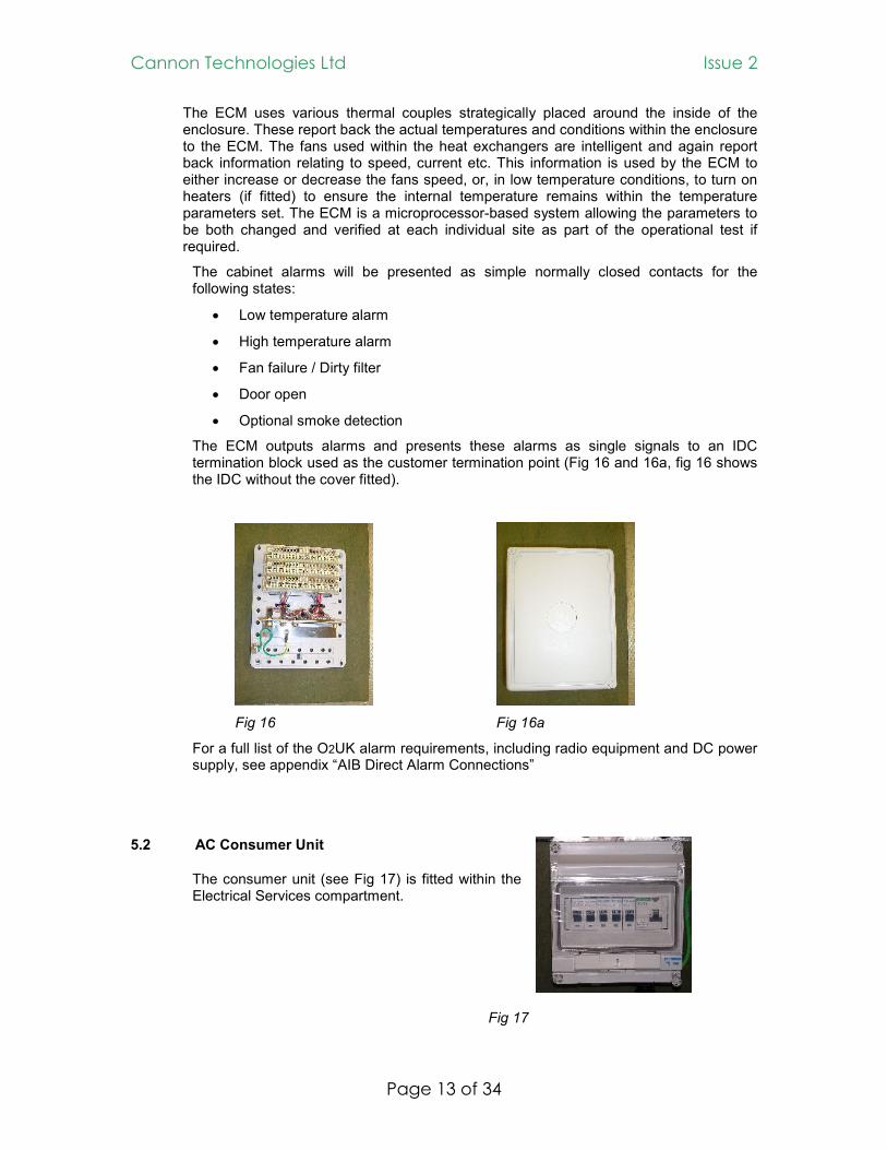
The ECM outputs alarms and presents these alarms as single signals to an IDC termination block used as the customer termination point (Fig 16 and 16a, fig 16 shows the IDC without the cover fitted).
Fig 16 Fig 16a
For a full list of the O2UK alarm requirements, including radio equipment and DC power supply, see appendix “AIB Direct Alarm Connections”
5.2 AC Consumer Unit
The consumer unit (see Fig 17) is fitted within the Electrical Services compartment.
Fig 17

Cannon Technologies Ltd Issue 2
Page 14 of 34
The consumer unit consists of;
• One pole 63-amp 100-ma RCCB for input terminations
• Two 6 amp MCB for 13 amp Test Equipment socket
• Two 16 amp MCB for DC power supplier
• One spare 6-amp
These items are designed and interconnected within a single sealed enclosure.
The AC consumer unit is supplied with two leads for connection and termination onto the RECs meter or fuse. A separate earth lead is connected to main earth bar for connection to REC’s cut outs.
5.3 DC Power Supply
On cabinets supplied before Apr 2007 an Eltek flat pack MPSU6000 switch mode unit is installed to supply 1 x 63amp DC power feeds for the 2G or 3G radio equipment, a 6amp DC power feed for the Comms supply and a 10amp DC power feed for the environmental control panel. The system comprises of 3 x 1500W rectifiers giving N+1 at maximum configuration. In addition to this 1 x string of 40-ampere-hour batteries are installed as standard to give a minimum back-up time of 10 minutes.
On cabinets supplied after Apr 2007 an Eltek flat pack switch mode unit is installed to supply 1 x 63amp DC power feeds for the 2G or 3G radio equipment, a 6amp DC power feed for the Comms supply and a 10amp DC power feed for the environmental control panel. The system comprises of 3 x 1800W rectifiers giving N+1 at maximum configuration. In addition to this 1 x string of 40-ampere-hour batteries are installed as standard to give a minimum back-up time of 10 minutes.
The DC system supplies the radio equipment and the environmental controls of the cabinet.
For further detail refer to the Eltek equipment handbook available from O2UK.
6 INSTALLATION
The following information is offered as a guide only and it is recommended that the services of a technically competent person be sought if any of the following conditions apply.
1. After excavation the soil is either of a peat, sand, clay or gravel basis
2. The water table is close to the surface
3. The area is prone to flooding
4. The area is known to be susceptible to either subsidence or slippage
5. Large amounts of standing water are present
The information issued is and must be treated as a guide only. As Cannon Technologies Ltd is not party to any of the following it cannot be held responsible for any of the civil construction.
1. site surveys 2. soil analysis

Cannon Technologies Ltd Issue 2
Page 15 of 34
3. construction of the concrete base 4. supervision of any installation work
It is the responsibility of the selected O2UK civil contractor to ensure the correct
methods of construction are incorporated within their specification.
6.1 Concrete Base Design
The following base recommendations are based on the requirements of the main housing only and do not take the soil conditions into account.
It is recommended that the base design should be in accordance with the steps defined below provided none of the above installation conditions exists.
1. It is recommended that the pad be cast in a position that will maintain a minimum gap of 100mm between the cabinet back panel and any adjoining wall or fence. This is to prevent the build up of debris, which could cause damp to be transmitted through the wall and block the rear filter inlet area.
2. Excavate a hole to dimensions shown on O2UK documentation
3. Fill the bottom of the excavation with hardcore to the depth recommended and using a suitable mechanical aid compact the hardcore and blind with sand. Position the Root into the excavated hole ensuring that the top surface is level in both axis and that it protrudes above the surface by a minimum of 25-mm. This is to ensure that the joint between the cabinet and the root is above the ground level.
4. It is recommended that a template/shuttering be manufactured to position and hold the cable entry ducts in position. The cable entry points into the root are to be sealed on both sides using “Plastijoint” supplied by “Fosroc Expandite Ltd”. The sides of the template/shuttering should be manufactured from unjointed sheets of plywood. They should be firmly propped to within a tolerance of ± 4mm. The template/shuttering must be removed after 4 days.
The concrete should be mixed to the following ratio, 1 part ordinary Portland cement: 1½ parts sand: 3 parts aggregate with a cement/water ratio of 0.5. Water should be obtained from Water Co tap supply. Pour the mixed cement/aggregate to a depth as specified within the O2UK documentation supplied.
The concrete should be vibrated to ensure complete encasement and compaction. The top surface of the base should be trowelled level to ± 1mm along its length and across its width.
5. The surface of the concrete should be protected immediately after casting with two layers of hessian laid over timbers set 75mm above the base surface. Protection should be left in place for four days in both hot and cold climatic conditions. The same period of time should be left before any work is started on the top surface.
6. Before installation of the cabinet the top surface of the base be must covered with a layer of “Bituthene” or other suitable waterproofing membrane. Using a suitable jointing mastic form a small bead around the top surface of the root. Remove the wooden transit blocks from the underside of the cabinet (See Fig 18)

Cannon Technologies Ltd Issue 2
Page 16 of 34
Fig 18 Lift the cabinet into position as described below in section 6.3; position the cabinet onto
the root and bolt down using the bolts supplied and attached to the inside of the cabinet. Before tightening completely, check the doors for correct alignment with their apertures. Check that the Cams and Door Locking Rods engage into their respective locations. If the door/doors appear to hang at an angle to the main aperture it may be due to some form of contaminate between the face of the root and the underside of the cabinet i.e. small pieces of aggregate. Loosen the securing nuts and check to ensure that the surfaces are clean apart from the mastic. If there is nothing between the two faces use shims to correct any out of tolerance; once corrected tighten the nuts securely. For full instructions on the installation of the cabinet to the root please see the instruction sheet attached within the appendices section 9.
6.2 Roadside Equipment Housing Positioning
In order for the environmental seals to perform as designed the Roadside Equipment Housing on its base must be aligned as per step 6 in section 6.1 above. The siting of the Roadside Equipment Housing should allow for 750mm space around the perimeter. The Roadside Equipment Housing should be positioned to avoid the following:
• Overhanging trees
• Areas of known flooding
• Areas of known subsidence
6.3 Handling
The cabinet will be supplied with four lifting lugs, two each side positioned at low level. Once the cabinet has been lifted into position the lugs shall be removed for safety preventing persons from injuring themselves on the protruding edges.
The operation to lift will consist of the following;
1. Attach the shackles through one end of each soft strap.
2. Attach one strap to each of the four corner lifting lugs. (See Fig 18 above)
3. Fit another shackle to the other end of the soft strap and position it to a spreader beam which would be hung from the crane above the cabinet.
4. The crane operator should gently lift the cabinet to check that the lift is central to the cabinet.

Cannon Technologies Ltd Issue 2
Page 17 of 34
5. Once this has been established and correct centre of gravity is found, it will allow a level, safe lift to be achieved.
6. Once the cabinet is positioned onto the root and loosely bolted into position the lifting lugs should be removed.
This equipment must be used with due regard to the Lifting Operation and
Lifting equipment Regulations 1998.
7. MAINTENANCE
There are no customer serviceable items associated with the mechanical structure of the Roadside Equipment Housing.
Should any of the doors become damaged due to a vandal attack they can be removed and replaced on site. Paint damage can be repaired roadside and instructions are included within Section 8 of the instruction manual on how this is to be achieved. Repair or replacement on other panel work making up the cabinet would be difficult to carry out in a road-side environment by untrained staff to meet the requirements of IP55. Cannon Datacom Ltd would state that during its time in the manufacture of both track and street side housings, vandalism has never damaged the panel-work to an extent where replacement has been necessary. The cabinet is of a complex construction and Cannon would offer its service to carry out any replacement to panel-work on a contract basis. Servicing of the defective component should be carried out off-site by a competent technician or alternatively returned to the supplier for repair. Replacement of the door would consist of the removal of the earth bonding strap, this will allow the door to be lifted off its hinges when opened greater than 90º; consideration
will need to be given to the weight and any relevant H&S issues. Seals will need to be replaced if damaged or after approximately 10-years depending on their condition. The seals will over time lose their memory and will retain the position of the closed door. This condition is more prevalent on cabinets which have been left unopened for a considerable period of time. The seal is a one piece welded seal and replacement is by manually pulling the seal from the frame and re-positioning the new seal. Failed Kaba dead locks can be replaced on site, the operator will need to open the door; firstly the retaining nut is removed from the rear of the lock barrel; once removed pull the dead locking lever from the thread. Remove the large retaining nut fixing the Kaba lock to the bezel; the failed lock can now be removed by pulling the barrel out forwards from the bezel, inserting the new barrel is a direct reversal of the above instructions. Filters need to be replaced annually or sooner if local conditions demand; to replace the filter element in either the door or back-panel (Fig 11 and 12) is achieved by un-screwing the retaining screws holding the cover in position. Once the cover is removed the dirty element can be removed and placed in a bag to contain the contaminants, replacement is a direct reversal of these instructions. Failed fans can also be replaced roadside see Fig 8, 9, 10, 11 & 12 and the description of how this is achieved within section 5.1.1 above. Before carrying out any work inside the fan tray switch off the power to the environmental system.

Cannon Technologies Ltd Issue 2
Page 18 of 34
7.1 Preventative Maintenance
Maintenance of the Roadside Equipment Housing would need to be an annual visit to undertake:
• Visual inspection of the mechanical structure
• Application of grease onto both lock and hinge mechanisms
• Replace filter elements
7.2 Health and Safety
Before undertaking any work within the cabinet it is recommended that the following points are observed;
• Personnel are fully compliant with any Heath and Safety issues regarding the work to be carried out.
• The mains power is isolated before undertaking any work.
• In wet conditions it is advised that work is either delayed or, if imperative, then a tent is erected over the cabinet for protection to the internal equipment.
• That any work carried out is done by competent well trained personnel with the appropriate skills.
• Personnel are issued with the correct method and instruction sheets for the work to be undertaken.
• Personnel are either issued with, or assurances made that, the correct working attire is available and worn to suit the work being carried out.
• Personnel have available all tools needed to carry out any work required
• It is recommended that the electrical equipment is tested on an annual basis.
8 Repair to damaged paint work
8.1 Touch-up repair, Powder coating only damaged
This type of damage has the appearance of scratch or scuffmarks only and generally arises during transit or installation of the cabinet.
Small areas of damage of this type can be readily repaired with C.C.S.C product type 600 polyurethane base colour/600 polyurethane curing agent series system.
The damaged area should be wiped free of dirt or deposits using a clean cloth and C.C.S.C product type 06-55 cleaning solvent, allowed to dry and the topcoat 600 polyurethane paint applied with a fine brush. Liberal application of the touch-up polyurethane paint must be avoided so as to minimize or prevent any visual colour differences between the touch-up paint and the original coating that might arise during weathering.

Cannon Technologies Ltd Issue 2
Page 19 of 34
8 .2 Powder coating damaged with the substrate exposed
If the powder coating has been damaged to such an extent that clearly visible areas of metal are apparent, the application of etching primers will be recommended prior to the application of the primer and polyurethane finishing system.
If corrosion or rusting of the metal surface has commenced, the areas should be wire brushed prior to the clean down stage. In this situation a coat of etching primer, C.C.S.C, 750 two pack epoxy primer Grey base/750 curing agent and 600 polyurethane base colour/600 polyurethane curing agent series will better assist in restoring the original protection of the coating system.
In both cases, care should be taken when wire brushing the affected area not to damage the surrounding intact powder coating.
Conventional spray, apply one coat C.C.S.C 600 series two pack polyurethane semi gloss finish, mixed with 600C hardener and thinned to application viscosity of 25-30 seconds BS B4 cup at 20ºC, air pressure 50-60 PSI. Mixing ratio of product is 5 parts 600 finish to one part 600 curing agent 22-00, require Dry Film Thickness 25 microns, equivalent to 60 microns Wet Film Thickness.
Use C.C.S.C thinner 25-03; allow the product to stand for 10 minutes before use and a minimum of 2 hours between coats. The product will be touch dry within 60 minutes but may take longer during low ambient temperatures.
For the repair of small defects we would suggest the following mixing proportions: Using a small foil baking type case and a metal teaspoon or scoop, measure 5 full spoons of the 600-colour finish into the foil case; add one spoon full of curing agent, mix together with a wooden spatula.
It is not recommended that plastic utensils are used as the solvents can melt some types of plastics.
When ordering materials for repairing small areas, quote for two pack wet touch up supplied in one litre cans, alternatively aerosols each containing 500ml can be supplied for larger areas.
C.C.S.C refers to:
Courtaulds Coatings Service Centre Unit A14, Railway Triangle Industrial Estate, Walton Road, Portsmouth. PO6 1TN Tel: 01705 201356 Fax: 01705 201358

Cannon Technologies Ltd Issue 2
Page 20 of 34
9. APPENDICES
1 Installation Instructions for a single Bay 2G/3G BTS Cabinet 2 Environmental Control System Including Electrical Assembly
Drawing S111838A Issue 1 3 230-volt AC Distribution Drawing P8811902 4 Test Certificate DC0124 5 Drawing: S111800A (Main Cabinet) 6 Drawing: S111803C (Direct Bury Root) 7 Drawing: S111803C (Root installation instructions) 8 Connection of Battery Back-up System - DC back-up P8811903-2
9 Alarm Mapping

Cannon Technologies Ltd Issue 2
Page 21 of 34
Appendix 1
Installation Instructions for a Single Bay 2G/3G BTS Cabinet
-48V
1. Remove the two BTS retaining clamps from the base support panel of the cabinet secured in position with 4 x M6 pozi pan head screws.
2. Remove the 4 x M5 pozi countersunk head screws exposed once the retaining clamps are removed from the base support panel; remove the base support panel from the cabinet.
3. This will expose two coach bolts holding the wooden plinth in position; remove both coach bolts from main cabinet. Open the door to the left hand end of the cabinet.
A further two coach bolts will be seen under the
wooden back-board within the electrical section,
these will also need to be removed.

Cannon Technologies Ltd Issue 2
Page 22 of 34
4. Affix certified lifting straps to the lifting lugs positioned on each corner of the cabinet; lift into position onto the root of the cabinet and line up the outside surfaces of the cabinet ensuring that the M10 holes in the root and cabinet are in line.
5. Inside the cabinet is a bag containing 6 off M10 x 50 hex headed bolts and washers; this is clipped to the rear cable tray.
6. Using these bolts, bolt the cabinet to the root; 4 bolts are used within the
main chamber and can be seen located beside the “Top-hat” sections. The other two bolts are used within the electrical compartment and fit into the holes to which the wooden plinth was attached.
7. Replace the base support panel (see item 2 above) and secure with the 4
x M5 pozi countersunk head screws retained from operation item 2 above.
8. Replace the BTS rear retaining clamp (heater end of cabinet) and secure with 2 x M6 pozi pan head screws retained from operation item 1 above.
9. Positioned on the right hand door internally is the removable platform; this is used to assist in the location of the BTS within the cabinet.
10. To release the platform from the door, raise the retaining toggle and lift the removable platform
Cannon Technologies Ltd Issue 2
Page 23 of 34
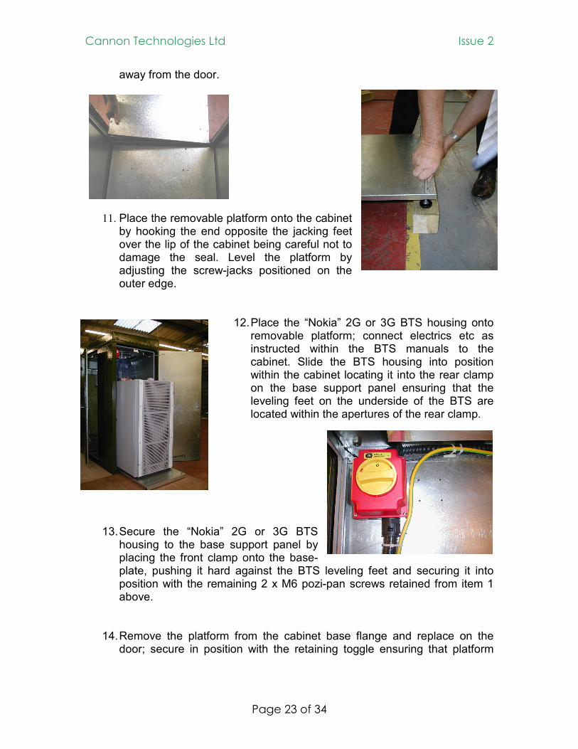
away from the door.
11. Place the removable platform onto the cabinet by hooking the end opposite the jacking feet over the lip of the cabinet being careful not to damage the seal. Level the platform by adjusting the screw-jacks positioned on the outer edge.
12. Place the “Nokia” 2G or 3G BTS housing onto removable platform; connect electrics etc as instructed within the BTS manuals to the cabinet. Slide the BTS housing into position within the cabinet locating it into the rear clamp on the base support panel ensuring that the leveling feet on the underside of the BTS are located within the apertures of the rear clamp.
13. Secure the “Nokia” 2G or 3G BTS housing to the base support panel by placing the front clamp onto the base-plate, pushing it hard against the BTS leveling feet and securing it into position with the remaining 2 x M6 pozi-pan screws retained from item 1 above.
14. Remove the platform from the cabinet base flange and replace on the
door; secure in position with the retaining toggle ensuring that platform

Cannon Technologies Ltd Issue 2
Page 24 of 34
does not foul the seal, obstructing the shutting of the door. This operation is a reverse of item 10 above.
15. Remove the lifting lugs by un-screwing the M10 fixing bolts; replace the
bolts after removing lifting lugs to seal the exposed holes.
The street furniture unit has also been developed for –48V dc operation under drawing number: S111800A Issue 3. The AC variant remains at Issue-2. For the ‘Installation Instructions’ for the -48V dc type cabinet, please refer to pages 16 to 20 of the 2 bay + battery connections instructions within the full Operational Manual which is available on request from O2.
End of document

Cannon Technologies Ltd Issue 2
Page 25 of 34

Cannon Technologies Ltd Issue 2
Page 26 of 34

Cannon Technologies Ltd Issue 2
Page 27 of 34

Cannon Technologies Ltd Issue 2
Page 28 of 34

Cannon Technologies Ltd Issue 2
Page 29 of 34

Cannon Technologies Ltd Issue 2
Page 30 of 34

Cannon Technologies Ltd Issue 2
Page 31 of 34

Cannon Technologies Ltd Issue 2
Page 32 of 34

Cannon Technologies Ltd Issue 2
Page 33 of 34

Cannon Technologies Ltd Issue 2
Page 34 of 34
Alarm Mapping for Cabinets Type ‘A’, ‘B’ and ‘F’ Alarm No.
Cannon Alarm Name Krone O2 Alarm Name
1 Power Alarm Prompt K1-1 Power Alarm Prompt
2 Power Alarm Deferred K1-2 Power Alarm Deferred
3 PDP K1-3 PDP
4 Smoke Alarm K1-4 Fire Alarm Stage 1
5 Link K1-5 Fire Alarm Stage 2
6 Door Open Alarm K1-6 Intruder Alarm
7 Link K1-7 Multicoupler Alarm
8 Link K1-8 Door Alarm
9 Link K1-9 Room Temperature Alarm Stage 1
10 Temperature Alarm K1-0 Room Temperature Alarm Stage 2
11 Fan/Thermistor/Blocked Filter Alarm K2-1 Air Conditioning Fail Alarm
12 Link K2-2 Gas Alarm Stage 1
13 Link K2-3 Gas Alarm Stage 2
14 Link K2-4 Flooding Alarm
15 Link K2-5 Site Mains Fail
16 Mains Fail K2-6 Mains Break Intelligent Shut Down
K2-7 Not Used
K2-8 Not Used
K2-9 Not Used
K2-0 Not Used