design and operation - legislative assembly of …5.4 design parameters - physical dimensions 6 5.5...
TRANSCRIPT

Criteria for Incinerator Design and Operation
vised June 1974 0 Re(Cl
TD 796 .057 1974
Ontario
Ministry Environmental of the Approvals Environment Branch

Copyright Provisions and Restrictions on Copying:
This Ontario Ministrv of the Environment work is protected by Crown copyright (unless otherwise indicated), which is held by the Queen's Printer for Ontario. It may be reproduced for non-commercial purposes if credit is oiven and Crown copyright is acknowledged.
It may not be reproduced, in all or in part, part, for any commercial purpose except under it licence from the Queen's Printer for Ontario.
For information on reproducing Government of Ontario works, please contact Scrvice Ontario Publications at copyrightolontario.ca

TABLE OF CONTENTS
1. Introduction 2
2. Classification of Wastes 3
3. General Requirements 4
4. Auxiliary Fittings 5
5. Incinerators for Types 1, 2 and 3 Wastes
5.1 Physical Description and Diagrams 6
5.2 The Combustion Process 6
5.3 Comparison of Basic Designs 6
5.4 Design Parameters - Physical Dimensions 6
5.5 Design Parameters - Combustion 10
5.6 Operating Requirements 11
6. Selection and Sizing Guide 12
7. Incinerators for Type 4 Waste - Pathological 13
7.1 Pathological Waste - Definition 13
7.2 Physical Description 13
7.3 Design Criteria 14
7.4 Crematory Incinerators 14
APPENDICES
A: Definitions 15
B: Design Assessment 17
C: Sample Calculations 26
D: Guides to Applicants for Certificates of Approval 44

n LJ
1. INTRODUCTION
These criteria have been prepared to assist in the design, assesment and operation of incinerators.
This publication has been produced after a thorough examination of existing practices. It has been found that difficulties of odour and soiling by particulate, encountered in the past, have been due to in- complete combustion and/or to poor operation.
Specific design parameters and operating procedures are included for incinerators burning No. 1, No. ?, No. 3 and No. 4 type waste. The basic principles that governed No. 5 and No. 6 type waste incinerat- ors impose special design requirements and are not dealt with.
It is not intended to stifle new ideas or to restrict design in any way. The basic principles behind these parameters are those inherent in
any good incinerator design. This publication deals in detail with factors associated with the conventional 3-pass type incinerator. They require that the conditions of' temperature, retention time, and good mixing needed for complete combustion are met. Associated with these are other details of design which are aimed at the goal of reducing the possibility of poor operation due to the human factor. Any design which fulfils these requirements will be acceptable.
As technical advances and practical observations provide more in-
formation, these data will be revised accordingly.
F
r:
2

2. CLASSIFICATION OF WASTES
E
r:
Waste platter play be divided into the following types:
Type 1 - Rubbish Mainly cellulosic waste. Lip to 10 percent pop-C0111I)LIStible, Lip to 25 percent moisture and a nlininlunl gross heat value of 6,500 BTU per lb. It does not include halogenated hydrocarbons, rubber, leather or wood.
Type 2 - Refuse A mixture of rubbish and garbage, with a moisture content of about 35 to 50 percent and with a gross heat value of 4000 - 6000 BTU per Ib.
Type 3 - Garbage Mixed aninial and vegetable waste from restaurants, cafeterias, etc_, a moisture content of 30 to 70 percent and a gross heat value of 1000 - 3000 BT II per Ib.
Type 4 - Pathological Carcasses, human and animal: organs and solid organic waste from hospitals, laboratories, abattoirs and amoral compounds; dispos- able operating theatre garments and swabs; maternity, sanitary and incontinent pads, disposable diapers and other similar mater- ials in which pathogenic bacteria might be present.
Type 5 - Industrial Gaseous, liquid or semi-liquid compounds, materials such as tars, paints, solvents, etc. Beat value dependent on materials handled.
Type 6 - Industrial Solid waste, such as rubber, plastic, wood, halogenated hydro- carbons, leather and similar materials. Heat value dependent on material handled.
3

3. GENERAL REQUIREMENTS
All incinerators constructed or installed should meet the fol- lowing provisions:
(a) Name Plate
Each incinerator shall be provided with a metal plate permanently attached in a conspicuous location. The plate shall bear the rated capacity of the unit, the type of waste for which it is designed and the manufactur- er's name. The manufacturer's or supplier's model number and the trade name of the unit may also be shown.
Ib) Physical Requirements
all conventional 3 pass incinerators should be equipped with:
1 i ) An ignition chamber within the incinerator where primary ignition and burning takes place, adequate in
size for its intended use:
Iii) A mixing chamber (usually placed between the ig-
nition and combustion chambers) where thorough mix-
ing of the products of combustion is accomplished by
utcreased velocities of the gases, afterburners, checker- work and/or changes of direction of the gas flow. It
Should be of such dimensions and shape, with mini- mum gas velocities, to permit complete mixing of the gases and solids arising from the fuel hed with the combustion air:
(iii) A combustion chamber where the unburned com- bustible material from the mixing chamber is complet- ly horned. This should be adequate in size to complete the combustion of all solid, semi-solid or gaseous pro- ducts when operated according to the manufacturer's operating instructions under any operating conditions likely to occur.
(c) Construction Refractory: Refractory walls. hearths, arches and suspended roofs slu,uld be constructed of high heat duty material, equi-
valent in quality to firebrick, conforming to As TM de-
signation C-24, P.C.E. 31-3' (309-20F).
An equivalent wall thickness of 4-1 ' inches is requir- ed for incinerators below 500 Ib hr. capacity an equi- valent of 9 inches is required for incinerators of and exceeding 500 Ih'hr. capacity. Firebrick should be laid with a thin -dipcoat" of high temperature cement mortar: thick "buttered" joints contribute to cracking and early deterioration of firebrick walls and arches. Provision must be made for expansion. Floors must be well insulated to prevent damage to foundations or subfloors.
Monolithic: Monolithic construction requires sturdy, easily remov- able formwork. Pouring, ramming or "gunning" must .
be executed in such a way as to prevent voids or poor bonding. Suspended roofs must he built so as to avoid radiation damage to tile hangers and supporting steel. Easy re-
placement of damaged or deteriorated tile should be one of the design considerations.
I nsulation: Insulation can be provided by use of ventilated air spaces, loose frill for roofs only, block insulation, insul- ating concrete or any comhinaiion of these systems which a ill ensure continuous protection of the surf- ace, casing or wall inw,lved. Loose fill insulation is not considered suitable for filling spaces between vertical walls, as it may pack or leave voids, creating hot spots. Insulation should be selected for characteristics which will endure high interface temperatures without deter- ioration, and provide suitable "coldface" temperatures. Where steel frame and steel plate construction replac- es common brick outer wall construction the inciner- ator steel casing surface temperature shall not exceed '40oF and for safety reasons should preferahly he
below I SOoF. (d) Incinerator Room
flee room in which the incinerator is installed shall be large enough to provide a clearance of not less than 3 feet on any side for examination and repair purposes, and in no case shall there be less than 6 feet at the front (charging door end). Air intakes shall be required from the outside atmos- phere to provide ample air for combustion and venti- lation at all times and so located as to avoid extremes of temperature (see page 10).
The room should be fire resistant and isolated to con- form to Municipal Building Codes.
r:
(e) Combustion Requirements A damper or other means should he provided late the combustion air supply (see page 9).
(f) Auxiliary Combustion Equipment The necessary incinerator operating temperatures shall be maintained by the use of auxiliary combustion equipment, as indicated in Table l (page I I).
Nuzzle-mix power burners should be fitted and adjust- ed to produce, if possible, a flame to blanket the entire mixing chamber passageway and to create turbulence so as to thoroughly mix the combustibles with the combustion air. This is needed to ensure complete combustion and to eliminate odour and smoke emis- sions.
Each burner should be provided with an automatic pi-
lot or ignition device and an approved automatic flame failure shut-off valve. Whenever the ignition and mixing chamber burners are not on during the complete combustion cycle, they shall be provided with a temperature sensing control- ler which will maintain the required temperaturegrad- ients throughout the incinerator. Auxiliary burners should be designed and located to ensure that the flame does not impinge on cold surf- aces before combustion is complete, and to avoid dam- age to the burner by excessive radiation of heat.
(9) Charging
Incinerators should be designed to minimize the possi- bility of overloading and piling of the waste during charging. New flue fed incinerators are prohibited.
r1 L J
4

E
4.AUXILIARY FITTINGS
4. AUXILIARY FITTINGS
(a) Breeching Screens or Spark Arrestors: Incinerators used for the disposal of waste type Nos. I, ' and 3 must have a spark arrestor on top of the stack. In situations where it would be difficult to maintain such a screen, a breeching screen may be
considered a satisfactory, substitute. In either case the screen wire should be of No. 14 gauge, and the mesh should be a No. 3 (5/16 openings) made using a heat resistant alloy.
A Breeching Screen shall be mounted in a suitable heat resistant sliding steel frame to facilitate removal for purpose of cleaning, examination and/or replacement. A sturdy box-like construction of heavy gauge metal to resist distortion is recommended. The breeching shall be enlarged to accommodate a screen of an area of at least double the breeching area. The preferred lo- cation of such a screen shall be in the vertical portion of the breeching. If, because of space considerations, a horizontal breeching is used, then a suitable clean out point shall be provided in the enlarged section of the
breaching ahead of the screen, and the screen shall be mounted at an angle of at least 450 to the vertical in such a manner that particulate may fall off freely. A Spark Arrestor for mounting on lop of the stack or chimney should be of the following type. It shall have a height above the opening equal to the maximum hor- izontal dimension of the stack or chimney. The screen should be shaped to form a tight seal to the stack. It is
also desirable that the wire box-like frame of the arres- tor shall be rigidly attached to an angle iron base which fits flush with, and nests around, the chimney or stack opening.
(b) Test Openings: Test openings for examination purposes shall be provid- ed in the ignition chamber, mixing chamber and combustion chamber. A two inch pipe with a threaded cap should normally be adequate, but the pipe should not extend into the furnace.
5

5. INCINERATORS FOR TYPES 1, 2 AND 3 WASTES
5.1 PHYSICAL DESCRIPTION
General experience has led to the use of multichamber incin- erators for the combustion of rubbish, refuse and garbage. The configuration of these incincerators falls into the two general types shown in Figure 1 and These are the Retort type in which the chambers are arranged in a U configura- tion, and the In-Line type in which the chambers are arrang- ed in a linear sequence. The choice between these layouts is usually imposed by prac- tical considerations of space and the relative proportions of the chambers, which are imposed by technical considerations.
(a) Retort Type: Fssential features that distinguish the retort type of design are as follows: (1) The arrangement of the chambers causes the combustion gases to now through 90 degree turns in both lateral and vertical directions. (_) The return flow of the gases permits the use of a common wall between the primary and secondary combustion stages.
A cut-a-way view of a retort incinerator is shown in Figure I.
(b) In-Line Type: Distinguishing features of the In-Line type design are as follows: ( I ) Flow of the combustion gases is straight through the incincerator with 90 degree turns only in the ver- tical direction. (') The in-line arrangement is readily adaptable to installations that require separated spacing of the chambers for operating, maintenance or other reasons. A cut-a-way view of an hi-Line multiple-chamber in- cinerator is given in Figure '.
5.2 THE COMBUSTION PROCESS
The combustion process in a multiple chamber incinerator proceeds in two stages: (a) Primary combustion of the waste in the ignition
chamber-. (b) Secondary or gaseous combustion. The secondary
combustion occurs in two chambers first in the mixing chamber and finally in the combustion chant- he r.
The primary combustion in the ignition chamber includes the drying and ignition of the solid refuse. This is achieved by the use of an ignition or primary burner when necessary. As the burning proceeds, the moisture and volatile compon- ents of the fuel are vaporized and partially oxidized in pass- ing from the ignition chamber to the mixing chamber via the flame port. The volatile components of the refuse and the products of combustion flow down into the nnixing chamber into which secondary air is introduced. These gases pass through the flames of a secondary burner which assists in initiating the second stage of the combustion process by providing the ne- cessary heat and mixing. Turbulent mixing resulting from high velocities and abrupt changes in flow direction, furthers the gaseous-phase reaction.
In passing through the curtain wall port front the mixing chamber to the final combustion chamber, the gases under go additional changes in direction accompanied by expan- sion and final oxidation of combustible components in the connhustion chamber.
5.3 COMPARISON OF BASIC DESIGNS
The factors which tend to cause a difference in performance of the two incinerator types are related to the location of the flame ports and the sizes of the chambers.
The changes of flow direction inherent in the retort type im- pose a design limitation on the size and position of the flame port, this limitation is not so severe in the case of the in-line type.
If the incinerator is not too large (capacity below about 750 Ib;'hr.) the retort type is superior because.
(a) The violent change in the direction of flow of the gaws aids in the mixing of the combustibles with the air;
Ib) The common wall between the ignition and combus- tion chambers tends to provide higher thermal effi- ciency.
However, as the charge capacity becomes larger the retort design gives rise to regions of low turbulence (dead spaces) particularly in the ignition and mixing chambers. I he great- er flexibility in flanteport design of the in-line type reduces the occurrence of these dead spaces.
For incinerators with capacities above 1000 Ibjir, the in- line type becomes superior.
No outstanding factors favour either the retort or in-line configuration in the 750 to 1000 Ib!hr. capacity range. The choice will be influenced by space limitations and charging conditions.
5.4 DESIGN PARAMETERS - PHYSICAL DIMENSIONS
(a) Grate Area: ( i ) Nlinintum area permitted: 3.5 square feet for all types of combustible wastes.
( ii ) Incinerators for rubbish (Type I waste) should
have an area of not less than I lug ptl
square feet,
where pH = pounds per hour of waste material to be incinerated.
( iii I Incinerators for Type ' waste shall have an area
of not less than 10 loll
square feet, where pH = log pH
pounds per hours of waste material to be incinerated.
( iv) Incinerators for garbage (Type 3 waste) should
have an area of not less than 8
1-pH H square feet, gP
where pH = pounds per hour of waste material to be incinerated.
The curves of Figure 3 represent the above mathentati cal relationship between the combustion rate and the grate area. The permissible deviation of the grate area is ( 0 to + 5%). Grate area may not he replaced by solid hearth area.
6

r: CHAMBER WALL FROM FLOOR TO ROOF (SHOWN CUTAWAY) CURTAIN wA L L EXTENDING FROM ARCH 70 ROOF
'SHOWN CUTAWAY
F
CHARGING DOOR
FIGURE 1. CUTAWAY OF ,4 RETORT
MULTIPLE- CHgIyIgER INCINERATOR
BRIDGE WALL
IGNITION CHAMBER
FLAME PORT
CHAMBER WALL FROM FLOOR TO ROOF (SHOWN CUTAWAY)
FIGURE 2. CUTAWAY OF AN IN- LINE MULTIPLE-CHAMBER INCINERATOR
(('ourtesy Los Angeles ('OUnty Air Pollution Control District)

90
35
30
25
W
15
10
s
0
i
I
I
I I I
I
, i
I I I
II
! I
I
!
I
1
11 ! I I
i
I
I
Ir {
I
. L
I
I
r
I I
i
I
'
1 I
-
I
I
CAPACITY (LBS. PER HR. I I I I I I I I 1 1 1 1(
d kA A
FIGURE 3. RELATIONSHIP BETWEEN THE HOURLY COMBUSTION RATE AND GRATE AREA
E
F
8

(b) Grate Length to Width Ratio (approx.) ( i ) Retorts up to 500 Ibs.lhr. 2:1
over 500 lbs./hr. 1.75:1 b 9
( ii ) In-Line Diminishing from about 1.6: 1 for 750 lbs./hr. to about 1 : I for 4000 lbs./hr.
t
6 capacity.
6
(c) Arch Height: The arch height may be calculated front the following equation: 4 I l. (ft-) = 3 (Grate Area in sq. ft.) IT (± 10%)
or it may be estimated from the curve of Figure 4.
(d) Charging Door: Top or side loading incinerator designs must be avoided unless adequate arrangements are made to distribute the charge evenly across the grate and to ensure that the freshly charged material remains nearest the charg- ing door.
The charging door shall be located at the end of the ignition chamber farthest from the flameport. and this door shall be in the wall which is at one end of the longer grate dimension.
Maximum height of the top of the door is to be three quarters of the arch height above the grate.
(e) Mixing Chamber: Downpass length from top of ignition chamber arch to top of curtain wall port - not less than 80 percent of the arch height.
(f) Combustion Chamber: The calculation of retention lime poses a problem of defining the gas velocity and the path taken by the gases, with questions of dead spaces arising. In order to standardize a procedure, the following method, which results in a good appmxinhation of the true situation, has been evolved.
The path distance from the curtain wall port to [lie exit port opening is defined as:
The straight line distance between the point on the curtain wall port nearest to the exit, and the point on the exit port nearest to the curtain wall port.
The cross-sectional area to be used to determine gas velocities, and to calculate the retention volume is de-
fined as: The area of the chamber in that plane perpendicu- lar to the walls, which is most nearly at right angles to the line of the path distance determined as above.
(g) fhe incinerator should be designed so as to avoid the occurence of regions in the interior through which the combustion gases do not pass, or in which turbulence is lower than that required to ensure satisfactory com- bustion.
In the design or assessment of incinerators such areas should be treated as if they were non-existent and be ignored when calculating volumes or path lengths.
IN Stack:
Stack height should be calculated by standard stack design procedure and should be of sufficient height to
000
JS Q
IA HA ' 3 GI
3 1 1
FOR DRY REFUSE AND "1( 11- VALUESUSE 1Cr%CURVE
FOR MOIST REFUSE ANO L W.
HE Are;/, ALUES tit .-
2 7 4 S 10 to ]a 40 ro
GRATE AREA (AG) l12
10a
Fig. 4. Relationship of arch height to grate area for multiple - chamber incinerator
ws 1 oa
provide adequate primary combustion chamber draft. the effective induction draft at air inlets to the incin- erator should be 0.10 in W.G. when the unit is oper- ating at rated capacity. (Assume equivalent III inlet vel- ocity pressure of 2 1 ft./sec.) Effective draft is computed as theoretical stack draft minus friction losses at design flow condilions.
After the minimum stack height which satisfies the draft requirements has been determined, attention should be paid to local land usage arid heights of sup- porting and adjacent structures. very attempt shall be made to prevent down-washing of effluent into ventilation air intakes or windows which can be open- ed.
These considerations may indicate the necessity of achieving exit velocities in excess of 36 ft./sec. This may be done (e.g. by coning), in which case an in- crease in stack height may be needed in order to maintain the necessary draft.
(i) Barometric Damper: A barometric damper will prevent an excessively high draft over the fuel bed. A draft of 0.1 inch W.G. should be maintained during the burning periods. The baro- metric damper is easily adjustable and should be set from time to time to maintain the required draft. It should be in an easily accessible location.
The area of the barometric damper should normally be equal in size to the area of the installed breeching.
Breeching Area Sq. Inches
Diameter of Regulator
113 1,,, 154 14"
?O1 16" ?55 18" 314 20" 380 ''"
45' '4"
9

( i ) if a chimney is less than 60 feet high and a relative- ly high draft (0.15 0,20) is required, reduce the area of the barometric damper by 10 percent; ( ii) if a chimney is over 60 feet high and a normal draft is required, (0.1 0.13) add 10 percent to the damper area for each additional 20 ft. of stack height.
If the required damper area is larger than the breech- ing area, this area may be achieved by the use of two or more dampers.
(j) Isolation Damper. A guillotine or slide damper should be used for isola- tion purposes when cleaning out the various zones or passes. This damper should he designed to meet the re- quirement of the Fuel Safety Branch of the Depart- ment of Energy and Resources Management and to give 90 percent closure only.
(k) Make-up Air: The incinerator shall be installed in a location where facilities for ventilation permit the intake of sufficient air for draft control and maintenance of the ambient temperature at safe limits. as well as satisfactory com- bustion of the waste.
Outside there shall be a permanent air supply inlet or inlets having a total cross sectional free area of not less than 500 sq. inches plus an increase of I sq. inch for every 4,000 BTU/hr input in excessof 500,000 BTU/hr.
BTU/hr. input will include the total of the gross heat- ing value of the waste (BTU/hr.) and the input (BTU/ hr.) of the auxiliary burners.
The air supply should be directed downward by duct- work or hoods, and should be released at a maximum height of ? ft. 6 inches above the incinerator room floor. The velocity of air entering the room should not exceed 250 feet per minute.
Weatherhoods may be required on natural ventilation systems to mini nize the effects of gusts and wind chill.
For large installations, fans, ductwork and diffusers may prove to be a more convenient and economical method of supplying make-up air. Provision can also be made for heating make-up air if necessary.
5.5 DESIGN PARAMETERS -COMBUSTION
To meet the requirements of solid fuel combustion, it is ne-
cessary that the air and fuel are supplied in proper propor- tions. Because the mechanism is one of fuel bed surface com- bustion, sufficiently large volumes of overfire air must be provided. The air and fuel, especially the combustible gases, must be (nixed adequately. Temperatures must be sufficient for ignition of both the solid fuel and the gaseous compon- ents. Furnace volumes must be large enough to provide the necessary heat release for complete combustion and finally the furnace proportions trust be such that ignition temper- ature, suitable gas velocities and gas retention time are maintained.
The following sununari/es the combustion design parameters.
(a)
(b)
Burners: Tlie recommended BTII requirements for burners are given in Table I on Page 11.
"Nozzle-mixing power burners" supplied with combus- tion air from a pressure blower shall he used for both the primary and secondary burners. Natural gas, liqui- fied petroleum gas (LPG), or No. ? fuel oil can be used for the incinerator burners.
Combustion Volume: To ensure complete combustion, sufficient volume must be provided to ensure that adequate retention time is available for the heat release from both the solid waste fuel and the auxiliary fuel from the burn- ers.
The total volume of the incinerator chambers should be based on a total heat release value (waste plus fuel) of about 25.000 BTU!cu.ft./hr.
(c) Combustion Air:
lil Total Air requirement Sufficient air (calcu- (batch charging operation) culated on the basis
of heat balance) to maintain a tempera- ture of 1600OF in the mixing and combus- tion chambers
Iii) Air Distribution Ports controllable up to:-
Overfirs Air Ports 70% of total air (ignition chamber) requirement Underfire Air Ports 10% of total air (ignition chamber) requirement Mixing Chamber Air Ports 20% of total air
requirement
(iii) Port Sizing:- Nominal inlet velocity pressure 0.1 in. water gauge
(iv) Air Inlet Port Oversize Factors:- Primary Air Inlet 1.2
Underfire Air Inlet 1.5 for over 500 Ib/hr to 2.5 for 50 Ib/hr
Mixing Chamber Air Inlet 2.0 for over 500 Ib/hr to 5.0 for 50 lb/hr
(d) Temperatures, Gas Velocities and Retention Time:
(i) Ignition Chamber Temperature:- 16000F plus or minus 10%
(ii) Mixing Chamber Velocities:- Flame Port @ 1600"F 55 ft/sec plus or
minus 20% (45 ft/sec - 65 ft/sec.)
Mixing Chamber 1600OF 35 ft/sec plus or minus 20%128 ft/sec - 42 ft/sec.)
Curtain Wall Port 1600OF 25 ft/see plus or minus 20% (20 ft/sec - 30 ft/sec.)
(iii) Combustion Chamber:- Minimum Gas Retention Times Rubbish (Type 1 waste) 0.3 second
Refuse (Type 2 waste) 0.5 second
Garbage (Type 3 waste) 0.5 second
Maximum Velocity at 1600OF 8.5 ft /sec.
C
10

(e) Draft Requirements:
(i) Theoretical Chimney Draft 0.35 ins, or more water gauge
(ii) Available Draft at Charging Door 0.1 to 0.2 ins.
water gauge
(iii) Velocity at Base of Stack Less than 36 ft/sec (12000F assumed for design purposes)
5.6 OPERATING REQUIREMENTS
To ensure that an incinerator is operated to the standards for which it was designed and to avoid air pollution, the follow- ing rules should be observed.
I. Incinerator operators should have an understanding of the principles of incinerator performance.
5. After a charge has been made and the burning is estab- lished, close the doors and adjust the overfire air ports.
n.
7.
8.
9.
Operators shall be in attendance for a sufficient time during operation to guarantee good operating perform- ance.
3. Incinerators shall be operated only between the hours 10.
of 7 a.m. and 5 p.m., or at such other times as may be permitted by regulations.
4. Incinerators are designed for a given rate of burning. Should the rate vary greatly from this design value, in-
complete combustion will result and smoke and odours will be emitted; therefore. (a) Do not use an incinerator until enough waste has accumulated to permit operation at the designed rate of burning. (b) Operate auxiliary burners for at least 30 minutes
11.
I, , warm up the refractory and establish adequate draft pi n r to charging the incinerator. 12.
(, ) Charge at regular intervals in such a way as to main- tain the designed burning rate without overloading the ignition chamber.
Regulate the draft so as to consume the waste at a
slow uniform burning rate without smouldering.
Use auxiliary burners during the entire burning cycle unless they are regulated to automatically maintain the designed incinerator operating temperature. It is essen- tial to maintain adequate heat input at the end of a
burning cycle. Timers should not be used to cut off the fuel supply before combustion has been completed.
Where-possible, burn waste without raking the fire. Careless stirring of the fire will cause heavy flyash emissions.
Allow the incinerator to cool down before dumping the grates. If this is not done, the draft which exists will cause heavy flyash emissions.
Keep the ash pit and grates clean. The grate must be kept free of obstructions to allow a free flow of air through the waste. A few empty tin cans thrown onto the grates after cleaning will prevent the waste in sub- sequent charges from packing and will assure a porous bed, with free access of air to the burning waste.
Clean out the miming and combustion chambers fre- quently. Provide means to wet down the deposits be- fore removing them, or use vacuum cleaning equip- ment for their removal.
Use an incinerator only on the duty for which it was designed and keep it in good repair. Few rules of good operation will be effective if either of these factors is
ignored.
TABLE 1
CLASSIFICATION OF WASTES AND RECOMMENDED
B.T.U. REQUIREMENTS FOR INCINERATORS
11
Approximate Moisture Incombustible Combustible Gross B.T.U. Minimum Principal Composition Content Solids Solids Value/lb. of Refuse Burner Input
Type Description Components % by Weight % % o (es fired) B.T.U./hr/lb Waste
1 Rubbish Combustible Rubbish 100 25 10 65 6500 in Mixing waste, paper, 1,000 cartons, rags, Chamber
floor sweepings
2 Refuse Rubbish and Rubbish 50 50 7 43 4300 1/3 in Ignition garbage Chamber 4,000
Garbage 50 2/3 in Mixing Chamber
3 Garbage Meat and Garbage 100 70 5 25 2500 1/2 in Ignition vegetable (Rubbish up Chamber wastes to 35 6,000
1/2 in Mixing Chamber
NOTE: The above figures on moisture content, ash, and B.T.U. as fired have been determined by analysis of many samples They are recommended for use in computing heat release, burning rate, velocity, and other details of incinerator designs. Any design based on these calculations can accommodate minor variations
11

6. SELECTION AND SIZING GUIDE
(a) Incinerator Capacity: Incinerators should be sized by conducting a survey to determine the amount of waste to be handled. The minimum burning capacity can generally be estimated by dividing the total pounds of waste per day by the burning hours/day, shown in the table below.
Application: Industrial (2 shifts) 7 hours per day
Commercial 6 hours per day
Hospitals 6 hours per day
Institutions and Hotels 6 hours per day
Schools and Office Buildings 2 hours per day
Apartments I hour per day
If a shorter burning period is required, a higher capa- city incinerator should be installed.
(b) Incinerator Sizing Guide: Use following table as a general guide - do not use for a specific application.
Due caution must be used since the increasing use of disposable products may make these values inaccurate. The design of the incinerator should be based on a
heat and materials balance according to the type of
waste to be incinerated. These listed values should only be used when no other source of information is avail- able.
(c) Typical Densities of Refuse
Type I Waste 10 lbs./cu. ft. Type 2 Waste 20 lbs./cu. ft. Type 3 Waste 35 lbs./cu. ft. Type 4 Waste 55 lbs./cu. ft. Garbage @ 601% moisture 35 lbs./cu. ft. Garbage @70%moisture 40 lbs./cu, ft. Garbage @80%moisture 45 lbs./cu. ft. Magazines & Packaged Paper 35 to 50 lbs./cu. ft. Loose Paper 5 to 7 tbs./cu. ft. Scrap Wood and Sawdust 12 to 15 lbs./cu. ft. Sawdust 20 lbs./cu. ft. Sawdust (impregnated) 30 Ibs,/cu. ft.
(d) Volume of Some Common Waste Collectors Garbage Can (18" x 24") 3.6 cu. ft. Garbage Can (16" x 22") 2.0 cu. ft.
Barrel 4.0 cu. ft.
Oil Drum (50 gallon) 6.0 cu. ft.
Classification Building Type Design Requirements For Waste Type
Approximate Quantities of Waste Produced
Industrial Building, Process Plants 5,6 Survey must be made
Factories 1, 2,3 Survey must be made
Warehouses 1, 2, 3, 5, 6 2 Ibs.1100 sq.ft.!day
C ommercial buildings Office Building 1 1 lb/100 sq.ft./day Department Stores 2,3 4 IN 100 sq.ft./dav
Shopping Centres 2,3 Survey must be made
(excluding food stores)
Supermarkets 3 9 Ib/100 sq.ft./dav
Restaurants 3 2 lb/meal/day
Drug Stores 2,3 5 lb/ 100 sq.ft./day
Banks 1 Survey must be made
Food Markets 3 4 16/25 sq.ft./day
Residential Apartments 2 5 Ib/bedroom/day
Schools Without Cafeteria 1 1016/room+li4 Ib/pupil; day
With Cafeteria 2 8lb/room+1i4 Ib/pupiliday Universities 1, _', 3, 4 Survey must he made
Institutions Hospitals General Waste _', 3 8lbs/bed/day
I lospitals Pathological Waste 4 5 Ibs/bed/day
Residences _ 3 Ibs/person dxn
Rest Homes 2 3 Ibs/person; day
Homes for Aged General Waste 2, 3, 4 5 Ibs/person dap
Hotels Hotels - 1st Class 3 5 Ibs/room daN
- Medium Class 3 5 Ibs/room,das
Motels 1 _' Ibs/roon daN
Miscellaneous Dog Pounds 4 Survey must be made
Vet. Hospitals 4 Survey must he made
Crematoria 4 Survcv must he made
E
12

7 INCINERATORS FOR TYPE 4 WASTE - PATHOLOGICAL
7.1 PATHOLOGICAL WASTE -DEFINITION
Pathological waste is defined to include all, or parts of, or- gans, bones, muscles, other tissues, organic wastes of human or animal origin, disposable operating theatre garments and swabs, maternity, sanitary and incontinent pads, disposable diapers, and other similar materials which might contain pa- thogenic bacteria.
Sources of Pathological Waste: Hospitals, laboratories, abattoirs, animal compounds, and similar sources.
Composition of pathological waste: For purposes of calculations, the following composition is to be assumed unless specific data is available:
85% Moisture 5% Incombustible Waste
10%Conibustibles
Gross heating value of material tas tired) = 1.000 BTU/lb.
7.2 PHYSICAL DESCRIPTION OF PATHOLOGICAL WASTE INCINERATORS
One of several possible design configurations of this type of incinerator is illustrated.
The example shown is similar to a retort-type multi-cham- ber incinerator but there are three important differences:
1. The use of a solid hearth instead of a grate;
The provision for heating the hearth by passing the products of combustion from the mixing chamber through a chamber beneath the hearth before they exit to the combustion chamber, permitting both transfer of heat to [he unexposed portions of the material lying on the hearth, and more rapid evapor- ation of fluids that spill upon the hearth or seep through it: and
3. The use of a side charging door.
SECOND AH'y COMB USTWN CHAMBFH
MIXING CHAMBE R FLAME PORT
SIDE VIEW CLEANOUT DOORS
FIGURE 5. CUTAWAY OF A PATHOLOGICAL WASTE INCINERATOR
13

7.3 DESIGN CRITERIA
1. General Considerations: Many of the design parameters of types 1, _' and 3
waste incinerators also apply to this type of inciner- ator. For this reason only criteria which differ from those given for types I, _' and 3 waste incinerat,.)rs arc fisted in this section. Criteria not given here should be made to conform with types I, ' and 3 incinerator criteria.
2. Chambers: The incinerator must have a minimum of three cham- hers, passes, or zones. The hearth is to he a solid hot hearth with an adequate grease lip (or trough about 4" wide x 21V' deep) in the primary chamber. Open grates, in general, are not suitable.
In general practice the hearth is designed for a burring rate of 10 Ibs.'hr.'sgAt. Chamber and burners must be designed to give a 0.5 second retention time at I800oF, downstream of the secondary burner flame, to inini- inize smoke and odour and to destroy bacteria.
A minimum of y inches of super-duty firebrick or equivalent refractory is reconlnlended. Insulation be- tween the refractory and the casing should be suffi- cient to provide low heat loss and all external casing temperature in the range of 160OF to 2000F.
Ignition Chamber: Dimensions of the ignition charn- her are to be determined as follows:
I i ) Hearth area I sq. ft/ 10 Ib/hr. 1 ii I Average arch height - from Graph of Fig. 6
( i i i ) Chamber volume based on I i ) and ( ii I and using an approximate hearth length to width ratio of
to 1.
3. Burners: Primary and secondary burners of the forced draft or ..power" type sliall be provided. Primary burners will provide at least 5000 BTU/lb of charge and secondary burners will provide at least 3000 BTU/lb. A minimum total heat input of 8000 BTU/lb of charge is necessary.
The secondary burner flame should be positioned so that all primary chamber gases pass through the flame, while avoiding impingement on refractory surfaces.
4. Stack: Calculations for stack design should be based upon a gas temperature of I600oF. To maintain available draft, stack design velocities should not exceed 40 ft./sec., although exit velocities may be increased (e.g. by con- ing) to 50 - 60 ft./sec, as dictated by land usage. In this case it may be necessary to increase the stack height in order to maintain the necessary draft.
The stack height should be calculated so as to provide (a) dispersion consistent with adjacent land usage, and (b) a minimum available draft of 0.25 in W.G. at the breeching. The latter is an absolute minimum draft provision for all pathological waste incinerators, and must re.ult in a draft of at least 0. I inch W.G. at the burner air inlets.
TABLE 2 - Temperatures & Gas Velocities
Required Gas Velocities Minimum Recommended Allowable
Item Temperature Values Deviation
Flame Port 1500OF 20 f.p.s ± 20%
Mixing Chamber 1500OF 20 f.p.L ± 20',,
Port at bottom of Mixing Chamber 1500OF 20 f.p.s. ± 20', Chamber below hearth 1800OF 10 f.p.s. 100
Port at bottom of Combustion Chamber 1800OF 20 f.p.s - 20 _
Combustion Chamber 1800OF 5 f.p.s ± 100%
Stack 160010F 33 f.p.s. ± 20%
52
20 0 50 100 ISO too Z50 3W
CAPACITY 16/hr
FIG: 6 - Graph of Arch Height versus Capacity for Pathological Waste incinerators.
7.4 CREMATORY INCINERATORS
Crematory incinerators are a special type of pathological in- cinerator requiring special mention.
The shape and size of the ignition chamber in crematory units is dictated by the dimensions of the casket. The same factors influencing the design of other pathological inciner- ators should be used for all other parameters of the cremat- ory.
Operating procedures which apply to other incinerators will not in general be applicable to crematory units due to the fact that at some time during the total operation, a higher rate of production of combustion products occurs.
E
r:
14

APPENDIX: A DEFINITIONS
Arch Height: I he vertical distance froin the grate and drying:uea surface to the inside or lower surface of the roof of the ignition dianlber at its highest point.
B aff le: Any refractory construction intended to change the direc- tion of flow of the products of combustion.
Breeching: A flue leading from the combustion device to its stack.
Breeching Screen: A screen mounted in the breeching to prevent embers or other ignited material from being expelled to the atmos- phere,
British Thermal Unit (B.T.U.): The quantity of heat required uh raise the temperature of one pound of water through 10 Fahrenheit.
Bridge Wall: The partition wall between (lie ignition chamber and the mixing chamber over which pass the gases and solids re- leased from the fuel bed,
Burners: (a) Ignition Burner:
A gas or oil fired device installed in the ignition cham- ber to dry arid ignite the material charged to the incil- erator.
(h) Mixing Burner: 1 gas or oil tired device installed in the mixing chamber to promote turbulence, and complete the combustion (,f smoke, combustible solids, gases or vapours, and to maintain a minimum temperature of about 16000F.
( Ix0OOO F in Pathologic Incinerators).
Capacity: i-he rate of waste incineration, usually expressed in pounds per hour, with the type of waste being stipulated,
Charging Door: The door, either hinged or sliding, on the front or side of an incinerator through which material is charged to the ignition chamber.
Checker Work: Multiple openings, through any wall, used to promote turbu- lent mixing or to direct the flow of gases or to prevent the emission of large buoyant pieces of paper, etc.
n
Underfire Air Air that passes through the fuel bed. Overfire Air - Air admitted into the ignition chamber
above the fuel bed.
(c) Secondary Air - Air admitted in the mixing chamber. (d) Tertiary Air Air admitted at Borne point in the gas
stream following the secondary airports.
(a)
(b)
Combustion Air:
Combustion Chamber: The final chamber in the multiple chamber incinerator in which combustion of the gases and solids from the mixing chamber is completed.
Curtain Wall: The partition wall between the mixing chamber and the com- bustion chamber.
Curtain Wall Port: The opening for the passage of gases from the mixing cham- ber to the combustion chamber.
Damper: A manually or automatically controlled device to regulate draft or the rate of flow of air or combustion gases. (a) Barometric:
A hinged or pivoted balanced blade placed so as to ad- roit air to the breeching, flue connection or stack, thereby automatically maintaining a constant draft in the incinerator.
(b) Guillotine: An adjustable blade installed it the breeching arranged to move vertically across the breeching, usually counterbalanced for easy operation.
(c) Butterfly: A plate or blade installed in a duct, breeching, flue connection or stack, which rotates on its axis.
(d) Sliding: An adjustable blade installed in a duct, breeching, flue connection or stack, arranged to move horizontally across the duct, breeching flue connection or stack.
Draft: The pressure difference existing between the incinerator or any component part and the atmosphere, which causes a continuous flow of air and products of combustion through the gas passage of the incinerator to the atmosphere. (a) Forced Draft:
The pressure difference created by the action of a fan, blower, or injector, which supplies the primary com- bustion air at above atmospheric pressure,
(b) Induced Draft: The pressure difference created by the action of a fan or ejector, which is located between the incinerator and the stack, or at the stack exit.
(c) Natural Draft: The pressure difference created by stack or chiuney due to its height and the temperature difference be- tween the flue gases and the atmosphere.
Dust Separation Equipment: A device that separates solid material from the gaseous med- ium in which it is carried,
Flameport: An aperture in the bridge wall.
Fly Ash: All solids, including ash, charred paper, cinders, dust, soot or any partially incinerated matter, carried in the products of combustion,
Fly Ash Collector: A device designed to remove flyash from (lie products of combustion.
Garbage: Refer to "Classification". (Page 3)
Gas Washer or Scrubber: Auxiliary equipment designed to remove pollutants in a wet form front the products of combustion.
15

Grate: A horizontal or inclined, stationary or moveable support for the fuel having suitable openings to permit underfire air to enter and pass through the burning fuel.
Heating Value: The heat released by combustion of a unit quantity of waste or fuel, measured in British Thermal Units (B.T.U.).
Heat Release Rate: The amount of heat liberated during the process of complete combustion and expressed in B.T.U. per hour per cubic foot of the incinerator volume in which such combustion takes place.
Incinerator: Equipment used for the burning of waste.
Industrial Waste: Refer to "Classification". (Page 3)
Mixing Chamber. A chamber following the ignition chamber in which the gases and solids leaving the fuel bed are given turbulence.
Multi Chamber Incinerator: An apparatus used to dispose of combustible wastes by burn- ing, consisting of three or more refractory lined combustion chambers in a series.
Patho"ical Waste: Refer to "Classification". (Page 3)
Refuse: Refer to "Classification". (Page 3)
Rubbish: Refer to "Classification". (Page 3)
Spark Arrestor; A screen device to prevent sparks, embers or other ignited material from being expelled into the atmosphere.
11
E
16

APPENDIX: B : DESIGN ASSESSMENT
E A QUICK REFERENCE GUIDE FOR ASSESSING INCINERATOR DESIGNS OF CONVENTIONAL THREE PASS TYPE INCINERATORS (Types 1, 2 and 3 wastes)
INCINERATOR DESIGN
ASSESSMENT
r
TYPE WASTE
NO. ITEM AND CALCULATIONS NO. SUPPLIED
MEET AMB
CRITERIA COMMENT
1 RATED CAPACITY, Ibs waste/hr 1
Ib/hr Iblhr
2 IGNITION CHAMBER LENGTH, ft. in. 2
3 IGNITION CHAMBER WIDTH, It. In. 3
4 RATIO IGN. CHAM. LENGTH TO WIDTH
2 =
3
= 4
5 (IRATE AREA, (a) REQUIRED, 1 0, + 5%)
TYPE 1 WASTE G.A. _ 1
_ _ 13 LOG 1 13 x 0 _ = TYPE 2 WASTE GA. _ --
10 LOG O 10 x
1
TYPE 3 WASTE GA. _ = _ 8 LOG 1 8x
GRATE AREA, (b) SUPPLIED
O x O 144 144 ft2 ft2
,,, 0.3636+ 6 - lOv ARCH HEIGHT = 1 333 (G.A.)
LOG (A. H.) = 0.125 +0.3636 LOG ( 55 )
= 0.125 + 0.3636 LOG i I
= 0.125 + 0.3636 x
= 0.125+
A, H.
A.H. RANGE = ft ft to
OR = 6
NOTE Circled numbers refer to items as shown in left hand column,
17

NO. ITEM AND CALCULATIONS NO. SUPPLIED MEET AMB
CRITERIA COMMENT
7 MAX. DIST. TOP OF CHARGING DOOR TO GRATE
= 0.75 (ARCH HEIGHT) =0.75 x O = 0.75 x = ft
= 7
8 IGNITION CHAMBER AUXILIARY BURNER
CAPACITY F x (LB. WASTE/HR) x BTU/hr
Ib waste/hr
= F x O x 01
= x x
= BTU/hr 8 BTU/hr BTU/hr
WHERE.
F QI
TYPE 1 WASTE 0 0
TYPE 2 WASTE 0.333 4,000
TYPE 3 WASTE 0.500 6,000
9 MIXING CHAMBER AUXILIARY BURNER
CAPACITY ? (1-F) x O x QM
= x x
= BTU/hr 9 BTU/hr BTUihr
WHERE
(1-F) QM
TYPE 1 WASTE 1.000 1,000
TYPE 2 WASTE 0.667 4,000
TYPE 3 WASTE 0.500 6,000
10 TOTAL AVAILABLE AUXILIARY BURNER HEAT
QAB = 0,92 x ( 0+0) = 0.92 x I + 1
10
= BTU/hr BTU/hr
11 NET AVAILABLE HEAT FROM WASTE
= O x _N! = x
= BTU/hr 11 BTU/hr
WHERE:
TYPE 1 WASTE, OW = 5865
TYPE 2 WASTE, OW = 3418
TYPE 3 WASTE, OW = 1500
NOTE: Circled numbers refer to items as shown in left hand column.
18

E
NO. ITEM AND CALCULATIONS NO. SUPPLIED MEET AMS CRITERIA COMMENT
12 TOTAL HEAT INTO INCINERATOR, OT
- 10 + 11 - BTU/hr 12 BTU/hr
13 HEAT AVAILABLE FOR HEATING GASES,
ASSUMING ADEQUATE INSULATION IS PROVIDED
IN THE ABSENCE OF MORE ACCURATE DATA, ASSUME 5%OF TOTAL HEAT INPUT IS LOST
TO WALLS
HEAT AVAILABLE = 0.95 x 12
= 0.95 x = BTU/hr 13 BTU/hr
14 F LOWRATE OF GASES THROUGH COMBUSTION
CHAMBER TO MAINTAIN TEMPERATURE OF
1600OF
- 13 x 0.63 x 10 6
= x 063 x 10 6
= Ib, gases 14 Ib/sec
sec.
15 RATE OF VOLATILIZATION OF WASTE
TYPE 1 WASTE 0.90 = FRACTION VOLATILIZED
TYPE 2 WASTE 0.93 =
TYPE 3 WASTE 0.95 =
FLOWRATE = F.V. x 1
3600
x Ib 15 Ib/sec
3600 sec.
16 AUXILIARY FUEL - NO. 201L -19,600 BTU/lb 16 BTU/Ib
NAT. GAS -22,000 BTU/Ib
17 AIR FOR AUXILIARY FUEL - USE.
14.0 Ibs air/lb No. 2 oil Ib, air
17.0 lbs. air/Ib Nat. gas 17 lb, fuel
18 FLOWRATE OF IGNITION CRAM. AUX. FUEL
O lb
= 18 lb/sec 3600 x 16 3600- sec
19 FLOWRATE OF MIXING CRAM. AUX. FUEL
O lb _
sec 19 Ib/sec
3600 x 16 3600 x
NOTE Circled numbers refer to items as shown in left hand column.
19

NO. ITEM AND CALCULATIONS NO. SUPPLIED
MEET AMB
CRITERIA COMMENT
20 FLOWRATE OF AIR FOR IGN. CHAM. AUX. FUEL
IASSUME 20"b EXCESS AIR, I.E. FACTOR OF 1.2)
= 1.2 x 0-8 = 1.2 x x = Ib 20 Ib/sec
sec
21 F LOWRATE OF AIR FOR MIX. CHAM. AUX. FUEL
IASSUME 20°o EXCESS AIR, I.E. FACTOR OF 1.2)
= 1.2 x 1 7 x 19
= 1 2 x x = Ib 21 lb/sec
sec
22 FLO%A4RATE OF AIR FOH WASTE COMBUSTION
- 14 I 15 + 18 + G' 20 + (3) _ + + + 1
Ib 22 Ib/sec
sec
23 FLOWRATE OF GASES THROUGH FLAME PORT
= (0.8 x 22 I + 15 + 18 + 20
_ (0.8 x I+ + +
_ + = Ib 23 Ib/sec
sec
24 FLAME PORT AREA W = 55 fps + 209"0)
(a) REQUIRED AT 16000E
52.1 x 23 - 0.972 x
55
= It 2 (± 20%)
(10 SUPPL IF0 = x = It2
>1
It` I12
144
25 TOTAL GROSS HEAT INPUT
C'TG - Q + (D + 1 0 x QwG)
_ + I x 1
= BTU/hr 25 BTU/hr
TYPE OF WASTE. 1 2 3
C`WG 6500 4300 2500
NOTE: Circled numbers refer to items as shown in left hand column.
r:
20
n
NO. ITEM AND CALCULATIONS NO. SUPPLIED MEET AMB
CRITERIA COMMENT
26 MIXING CHAMBER AREA IV = 35 tps t
20% (a) REQUIRED AT 1600OF
52.1 x (4 - - 1.488 x
35
= It2 (± 20%)
1b) SUPPLIED
= x = It2 26
144 1t2 It 2
27 CURTAIN WALL PORT AREA IV =25 fps ±
20%)
(al REOUIRFO AT 1600OF
52.1 x14 _ 7.08 x
25
= It2 1± 20`KI
Ib) SUPPLIED
= x ft2 27
144 It2 It2
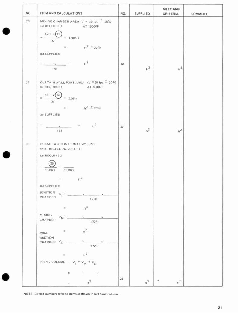
28 INCINERATOR INTERNAL VOLUME
INOT INCLUDING ASH PIT)
la) REOUIHFU
= 25 - 25.000 25.000
_ It3
(hl SUPPLIED
IGNITION V = x x I
CHAMBER 1728
= It3
MIXING VM= x x CHAMBER
1728
It3 COM
BUSTION CHAMBER VC x x
1728
= ft3
TOTAL VOLUME = V + V + V I M C
28
= It3 ft3 ft3
NOTE Circled numbers refer to items as shown in left hand column.
21

NO. ITEM AND CALCULATIONS NO. SUPPLIED
MEET AMB
CRITERIA COMMENT
29 DOWNPASS LENGTH (TOP IGN. CRAM. ARCH
TO TOP CURTAIN WALL PORT)
' t 0.8 6 = 0.8 x = It 29 It It
30 STACK OR BREECH DIAM.IV 1--' 36 fps at 1200oF)
41.9 x 14 = AREA REG. = 1.161 x 14
36
= 1.161 x
= ft2
DIAM., IN., L, 13.54 AREA, ft2 = 13.54 x 30
_ in. in. dram in.diam
31 COMBUSTION CHAMBER SHORTEST LENGTH
(DEFINED AS SHORTEST DISTANCE BETWEEN
EDGE OF CURTAIN WALL PORT AND EDGE OF
STACK OR BREECH)
31 ft
NOTE: Circled numbers refer to items as shown in left hand column.
C
22

C
C
NO. ITEM AND CALCULATIONS NO. SUPPLIED
MEET AMB
CRITERIA COMMENT
32 COMBUSTION CHAMBER CROSS SECTIONAL AREA (DEFINED AS BEING MOST NEARLY
PERPENDICULAR TO (3) = x - ft2 32
144 ft2
33 COMBUSTION CHAMBER VELOCITY (V -5 8.5 fps) AT 1600OF
52.1 x 14 - 52.1 x V = - = fps 33 3.5
32 fps fps
34 COMBUSTION CHAMBER RETENTION TIME
31 i
t = _ = sets
33
34 sec sec
35 STACK OR BREECH LOCATION
O.K.or X - MOVE FURTHER AWAY FROM
WALL PORT 35
36 OVERFIRE AIR PORT AREA
la) REQUIRED
= 0.632 x 1.2 x 0.7 x 22
= 0.531 x
= f t
2
(I)) SUPPLIED 2
in 2 _- -- = ft 144
36 ft2 ft2
37 UNDERFIRE AIR PORT AREA
(a) REQUIRED
- 0.632 x 0.1 x 0.0 = 0.0632 x x =
It2
(b) SUPPLIED
2 =
in ft2
144 37
It2 ft2
38 MIXING CHAMBER AIR PORT AREA
(a) REQUIRED
0.632 x 0.2 x 40 x 22
= 0,1264x x
= ft2
(h) SUPPLIED
2
= in
= 2 f 38 t 144 2 It It2
NOTE: Circled numbers refer to items as shown in left hand column.
23

NO. ITEM AND CALCULATIONS NO. SUPPLIED
MEET AMB
CRITERIA COMMENT
39 OVERSIZE FACTORS
40 lO 39 40
501b/hr 2.50 5.00 39 100 2.39 4.67
150 2.28 4.33 40
200 2.17 4.00
300 1.95 3.33
400 1.72 2.67
500 1.50 2.00
600 1.50 2.00
1000 1.50 2.00
41 IGNITION CHAMBER TEST OPENING 41
42 MIXING CHAMBER TEST OPENING 42
43 COMBUSTION CHAMBER TEST OPENING 43
44 NAME PLATE X - NOT SHOWN
V/ = SHOWN 44
NOTE: Circled numbers refer to items as shown in left hand column.
C
E
24

SOURCE OF CONSTANTS USED IN INCINERATOR DESIGN CHECK . AIR MANAGEMENT BRANCH
C 4. III RT in 53.5 x 2060 - _ - = 5.
x Area - x Vel. P Vel. 14.7 x 144
m 6 5' I .
DESIGN PARAMETERS INCINERATOR CRII+RIA - x
Vet.
here in = (Ibs/sec) gases
Vel. = allowable velocity 9)
11. 28. 1 otal volume of the incinerator chambers should be
based on a total heat release value of waste + fuel of
14. 11 for combustion products +excess air 15,000 BTU' tt3 hr.
IWWIF = 12 000
B1 U 21). Design Parameter ,
70OF Ib mole
N.B. The constant derived below has been adjusted to suit a detailed anal} sis of gases front typical waste
30. Same as 24, 26, 27 except based on absolute temper- ature of 16600R.
compositions. 1660 constant = 5'. I x = 41.9
Ills gases Ib mole '7 Ib I hour '060 = Q x x x
sec 12,000 B1 U' lb mole 3000.ec 4:\ Diameter = z where U and A are in inches and
= Q x 0.63 x 10.6 in,:bes-
Where Q = BTU 'Ilr (teat available to maintain temper- ature of 16000F
15. Design Parameters
16. Higher heating values of No. '_ oil and natural gas.
17. These values were calculated from the composition o1'
oil and gas, 11-4 11,0, C ---> CO,.
Material balance:
Air for waste combustion = total gases (waste gases
+ ign. chain. aux. fuel
+ Mix. sham. aux. fuel
+ air for ign, chain, aux. fuel
+ air for nix, chain. aux. fuel)
13, 80%of air required for waste enters via ign. chamber
Vol. = nn
Use 20% excess air for auxiliary fuel a 1.2
RT ft' P sec
Area - Volume rate of Flow
Velocity ft,
4:\Ix144 Al=ft= n
ll:\ 13.54
33. Same as 24, 36, 27.
36. Velocity = 4005 V.P.
= 4005 0.1
= 1-'66 FPM
or 2 I. l fps
V.P. = inches water
density of air
0.075 1b/ft3
\ = Q V
Ib air ft3 sec \rea = x - x
sec 0.075 Inn air L I ft
0.632 x lb air sec
\rea to be used = above area x oversize factor
For overfire air port, oversize factor = I._'
700 of air Haste conies through overfire air port.
37. Same as 36 except 10% of air comes through underfire air port, and oversize factor depends on capacity of
incinerator - i. e. 3`)
3H. Smile as 36, except 20% of air comes in via mix. cham-
ber air port. Oversize factor 40
25

APPENDIX C : SAMPLE CALCULATIONS
The following examples are intended to indicate how these 4. criteria have been used in the preliminary stages of produc- ing incinerator designs for the combustion of Types 1. 2, 3
and -1 Wastes.
INCINERATOR DESIGN EXAMPLE - NO. 1
OBJECT: To design an Incinerator for an office building with 30,000 sq. ft. floor area.
This will be type I waste.
There will be approximately I lb/ 100 sq.ft./day. i. e. 300 Ib/day.
Allow '_ hours burning time.
Therefore, design for 150 Ib/hr.
Use retort type design.
1. Grate Area: capacity
GA = 150
5.
6.
7.
8.
9.
Charging Door Height 0.75 (arch height) 25 inches 2 feet 1 inch
No ignition chamber burner required.
Mixing chamber burner 150,000 BTU/hr
Total Available Auxiliary Burner Heat
QA 13 0.92 X (0 + I X0.000)
= 138,000 BTU/hr Total Heat Into Incinerator
= 0 + heat available from waste.
138,(x)) + X230,000
= 1,018,000 BTU/hr
Heat Available for Heating Gases,
Assuming Adequate Insulation is Provided In the absence of more accurate Data, assume 5%of total heat input is lost to walls. Heat Available 0.95 x 1,018,000
= 965,000 BTU/hr
10. Flowrate of Gases through Combustion Chamber to Maintain Temperature of 1600OF:
13 log (capacity) 13 log 150 = 9 x 0.63 x 10-6
150 = 965,000 x 0.63 x 10-6 (-0 + 5%) 33 sq ft 5
13 x 2.1761 . . , .
= 610,000 x 10-6
2. Length/Width Ratio 2:1
Let width = a
Then a x 2a = 5.33
a= 5.3=1.63
= 19.5 in,
.
Say 20 inches
Length = 40 inches width = 20 inches
Area = 800 sq. in. = 5.55 sq.ft. satisfactory
Arch Height:
= 1.33 (5.55) 0.3636
Log (AH) = 0.125 + 0.3636 log 5.55
= 0.125 + (0.3636 x 0.7443) = 0.396
All = 2.5 feet
Allow for arch say: 2 feet 10 inches
COMBUSTION CHAMBER
= 0.61 Ibs of gases/sec
11. Rate of Volatization of Waste:
Flow rate
3000
12. Auxiliary Fuel:
Natural Gas = 22,000 BTU/lb
13. Air for Auxiliary Fuel:
17.0 Ibs of Air/lb of Nat. Gas
14. Flowrate of Ignition Chamber Auxiliary Fuel:
No ignition chamber burners, .'. No Auxiliary Fuel
15. Flowrate of Mixing Chamber Auxiliary Fuel:
F.V. x Capacity
3600
Capacity = 150lb/hr Fraction Volatized for type I waste = 0.90
0.90 x 150 = 0.0375lbs/sec
50,000
3600 X 1 _' 22,000 x 3600
16. Fbwrate of Air for Ignition Chamber Auxiliary Fuel: 2'-l0,
No Ignition Chamber Burners
17. Fbwrate of Air for Mixing Chamber Auxiliary Fuel:
(Assume 20% excess air i.e. factor of 1.2)
1.2x 13 x 15 = 1.2x 17x0.00189 = 0.0386lbs/sec.
C
I]
26

18. Flowrate of Air for Waste Combustion: 22. Mixing Chamber Area:
= 10 0+0 + IS + Required at 1 600°1'
= 0.61 (0.0375+0.00189+0.0326) 52.1 x 10
= 0.61 0.078 35
= 0 532 Ibs/sec E . . = 1.488 x 0.61
= 0.885 sq. feet
Say 20" x 7"
= 140 sq. in.
= 0.97 sq.ft. (0.885 + 10%)
19. Flowrate of Gases Through Flame Port
= (0.8 x 18 + I 1 +- 14 + IS
= (0.8 x 0.532) + 0.0375 + 0.00189 = 0.4659lbs/sec
20. Flame Port Area (V = 55 fps ± 20%) at 1600OF
Required 52.1 x(-,,-))
= v = 0.694 x 0.4t, 59
55 = 0.3_'6 sq. ft.
Say 7" square = 49 square inches = 0.33 sq. ft.
E
21. Total Gross Heat Input (QTG)
QTG =(D + t, + ((D x QWG)
QWG for type 2 waste = 0,500
= 0 + 150,000+ (6,500x 150) = 150,000 + 975,000 = 1,1 25,000 BTU/hr
23. Curtain Wall Port Area: (V = 25 fps ± 20%)
a) Required = 1600OF
_ 2.1 + 0.61 25
2.08 + 0.61
1.26 sq.ft.
Say 20 x 9" = 180 sq. in. = 1.25 sq.ft.
24. Downpass length:
Not less than 0.8 x Arch height
i.e. Not less than 0.8 x 2.44 feet = 1.95 feet = I' 1 1"
Available 2' 10" - (7" + 9") _
Ash Pit must be at least 5" deep.
Say 1' 3" with downpass length of (,, 10"
+ 1' 3") - (7
91,
1'6"
Therefore, combustion chamber dunensions are:
4' 1" x 1' 8" x (3' 4" 7" - 4") - (4" to allow for brick thickness)
= 4.08' x 1.67' x 2.42
= 10.5 ft.3
25. Incinerator Volume:
Requires I,- 125,000 - = 45 cu.ft.
25,000
Actual Volume = 16.5 + 4.1 + 20
(combustion) (mixing) (ignition)
Require
= 41.5 cu.ft.
4 cu. ft. extra (approx.) 4
Add - ft. to ash pit depth 1.8 x 4.08
Say 7" Overall depth therefore increased from 4' 1" to 4' 8"
27

26. Stack or Breech Diameter (V = 36 fps at 1200')F) Area Required
41.9 x 10
28. Combustion Chamber cross sectional area:
'Al x 1.67 sq. feet 4.U; sq. ft.
36
= 1.161 x 0.61
= 0.79 Sq.
= 0.79 sq. ft.
Diam = 13.54 (Area ft, )0.5
= 13.54 x 0.,1)9 = 12.1 in. SITI'A I ED ON TOP OF CHAM1iFR
12' 3'//" 4-
i
i
-- /18" 3%
11
27. Combustion Chamber shortest path:
_ [ (1.16)2 + (3.902 ]0.5
( 16.3)0.5
4 ft. approxvnately
29. Combustion Chamber Velocity:
_'.l Velocity
52.1 x 0.61
4.03
= 7.11 ft/sec (satisfactory)
30. Retention Time in Combustion Chamber: 7.9
4.02 - 2 sec. (adequate)
31. Overf ire Air Port Area:
a) Required = 0.632x 1.2x0.7x 18
= 0.632 x 1.2 x 0.7 x 0.532
= 0.284 sq.f.t
32. Underf ire Air Port Area:
a) Required
= 0.632x0.1x228x 18
= 0.632x0.1x2.28x0.532 = 0.070 sq. ft.
33. Mixing Chamber Air Port Area: a) Required
= 0.632 x0.2x4.33x0.532 = 0.292 sq.ft.
Drafting office to complete drawings using these three chamber internal dimensions.
NOTE: Combustion chamber is oversized and distance between curtain wall and the opposite wall can be re-
duced as necessary to accomodate thickness of curtain wall.
1-1
28

APPENDIX C 2
INCINERATOR DESIGN EXAMPLE - NO. 2
OBJECT: Design an incinerator for a 100 bedroom apartment building.
PROCEDURE: Ilse the "Incinerator Design Criteria" and the "Incinerator Design Check" as aids. The steps taken to arrive at an accept- able design are given below. Page numbers refer to the "In- cinerator Design Criteria" and Item No's. refer to items in
the "Incinerator Design Check".
1. Capacity & Type:
From Page 12, incinerators for apartment buildings should be designed for 5 lbs/bedroom/day of Type 2
waste. Total waste to be burned per day = 100 x 5 =
500 Ibs of Type 2 waste.
From Page 12, the incinerator should be operated for 1 hour per day. This means the incuterator should have
a capacity of 500 Ibs per hour of Type 2 waste.
Use a "retort" type incinerator for this application, as it should result ut a higher thermal efficiency (Page 6) than the "in-line" type.
2. Ignition Chamber: (Item No. 5 (a))
From Page 6, the grate area should be equal to
pll ,
ft- 10 log pH
for Type 2 waste where pH is the capacity in pounds per hour.
500 2 Grate area =
0 x2 .70 = 18.50 ft
Allowable deviation is (-0, + 5%)
.'. Actual grate area must be within the range 18.50 - 19.45 ft2
From Page 1), the length to width ratio for a 500 lb/hr retort incinerator should be 2:1
Let X grate width
2X = grate length
2X-' = 1 g.50
X2 = 9?5
X = 3.04 ft
2X = 0,08 ft
Make actual grate dimensions 3' 0" x 6' 3", which
result in a grate area of 18.75 ft'
3. Arch Height: (Item No. 6)
From Page 9, arch height may be calculated as follows: 4
4 HA = - (Grate Area)
1 1 + 10%
IiA
3
1.333 (G.A.) 0.3636 + 10%
log (I IA) = 0.125 + 0.3636 log (G.A.)
= 0.125 + 0.3036x 1.273
= 0.588
HA = 3.87 ft ± 10%
I IA range = 3.48 4.25 ft
Make arch height equal to 4' 0"
4. Top of Charging Door: (Item No. 7)
From Page 9, the maxhuum height of the top of the door is to be three quarters of the arch height above the grate.
Make top of door 0.75 x 4.0, or 3' -- 0" above the grate.
5. Ignition Chamber Auxiliary Burner: (Item No. 8)
From Page 1 1 (Table 1), Type waste requires an Ig-
nition Chamber burner of 4,000 x 1/3 or 1333 13TU/hr per lb waste/hour.
Required capacity = 1333 x 500 = 667,000 1f1 U/hr
As the apartment building will he heated by natural gas,
use natural gas for the burner.
6. Mixing Chamber Auxiliary Burner: (Item No. 9)
From Page 11, (Table 1), Type '_ waste requires a
Mixing Chamber Burner of 4000 x 213, or 3,667 BTU/hr per Ib waste/hour. Use a natural gas fuel
Required capacity = 2,667 x 500 = 1,333,000 BTU/hr
7. Total Available Auxiliary Burner Heat: (Item No. 10)
Convert higher heating value to lower heating value.
Qr1 B - 0.92 (667,000 + 1,333,000)
1,840,000 BTU/hr.
8. Net Heat Available from Waste: (Item No. 11)
From Page 1 1, Type _' waste has a gross heat value of 4300 BTU/lb. This corresponds to a lower or net heat- ing value of 3418 BT LJ/1b.
Available heat = 500 x 3418 = 1,710,000 BTU/hr.
9. Total Available Heat Into Incinerator: (Item No. 12)
QT = 1,840,000 + 1,710,000 = 3.5 50,000 1111 hr
10. Heat Available to Heat Gases: (Item No. 13)
ASSUme 530 of available heat is lost to walls.
Ileat available = 0.QS x 3,550,000 BTU hr,
3,370.000 13111,1 11
29

11. Flowrate of Gases Through Combustion Chamber to Maintain a Temperature of 1600OF: (Item No. 14)
The gad tlowrate may be found by multiplying the available heat value calculated above, by 0.63 x 10-('.
This constant is derived at the back of the "Check" booklet.
Flowrate = 3.370 x 106 x 0.63 x 10-6 = 12 Ibs gases/sec
12. Rate of Volatilization of Waste: (Item No. 15)
This quantity is equal to the burning rate minus ash production rate.
500 x 0.93 Flowrate = = 0.1290 lbs gases/sec
3600
13. Auxiliary Fuel: (Items 16 & 17)
Natural gas has a heat value of 22,000 BTU/lb and requires 17.0 lbs air (theoretical) per III of gas for combustion.
14. Flowrate of Ignition Chamber Auxiliary Fuel:
(Item No. 18)
Flowrate = 667,000 - 0.00842 Ibs/sec
3600 x 2,000
15. F lowrate of Mixing Chamber Auxiliary Fuel: (Item No. 19)
1,333,000 Flowrate = - 0.01683 Ibs/sec
3600 x 22,000
16. Flowrate of Air for Ignition Chamber Auxiliary Fuel:
(Item No. 20)
Assume 20% excess air is used.
Flowrate = 1.2 x 17.0 x 0.00842 = 0.1718 Ibs/sec
17. Flowrate of Air for Mixing Chamber Auxiliary Fuel: (Item No. 21)
Assume 20% excess air is used.
Flowrate = 1.2 x 17.0 x 0.01683 = 0.344 lb/sec
18. Flowrate of Air for Waste Combustion: (Item No. 22)
This value is computed from a mass balance and will result in the attainment of a theoretical temperature of 1600OF in the incinerator.
20. Flame Port Area: (Item No. 24)
From Page 10, the flame port gas velocity must be 55 ft/sce + at 16000F.
5 2.1 x 1.460 , + Area Required= - - = 1.39 ft` - 20%
55
Area Limits = 1.1 1 - 1.67 ft,
` Make flame port dimensions 8" x
, an area of 1.33 fr.
21. Mixing Chamber Area: (Item No. 26)
From Page 10, the mixing chamber gas velocity must be 35 ft/sec ±
20% at 1600oF.
52.1 x 2.12 , + Area required = = 3.15 ft` - 20%
35 Try mixing chamber dimensions of 9" x 4' 0". In order to have a reasonable sized ash pit, make total internal height of this chamber and the combustion chamber 6' 6". (Revise dimensions if found necessary in sub- sequent design calculations)
22. Curtain Wall Port Area: (Item No. 27)
From Page 10, gas velocity through this port must be 25 ft/sec ±
20% at 16000F.
5_'.1 x 2.1_ , Area required = 5 = 4.41 ft- - -10%
Make curtain wall port 2' 0" x _'' 0".
23. Total Gross Heat Input: (Item No. 24)
Q1G = auxiliary burners' heat + gross heat from waste
2.00 x 10⁶ + 500 x 4300
= 4.15 x 10⁶ + 106
4.15 x 10⁶ BTU/lu
24. Required Incinerator Internal Heat Release Volume: (Item No. 28) Volume required is to be based on a heat release rate of 25,000 BTU/hr/ft3 Page 10.
Volume required 4.15 x 10⁶ BTU/hr
25.000 BTU/hr/ft3
166ft3 Flowrate of air = total gas flowrate 25.
- (waste gases + ignition chamber air and fuel + mixing cham- ber air and fuel)
= 2.12(0.129+0.008+0.172+ 0.017 + 0.344)
= 1.450 lb. air/sec
19. Flowrate of Gases Through Flame Port: (Item No. 23)
From Page 10, 80% of total required air enters the
Downpass Length: (Item No. 29)
Downpass length, defined as the vertical distance from the top of the ignition chamber arch to the top of the curtain wall port, must be greater than or equal to 0.8 x Arch Height, which in this incinerator works out to be 0.8 x 4.0, or 3' 2" Actual downpass length = 4' 6"
26. Stack or Breech Diameter: (Item No. 30) From Page 11, stack or breech area should be such that gas velocity will be less than 36 ft/sec at 12000F.
incinerator prior to the flame port. 41.9 x 2.12 d
, 2 f ` Flowrate of gases = (0.8 x 1.450) + 0.129 + 0.008 Area Require
36 = .46 t
+ 0.172 1.160 + 0.309 = 1.469 lb Minimum breech diameter= 13.54 46 = 21.2 in.
gases/sec Make breech diameter = 22"
30
C
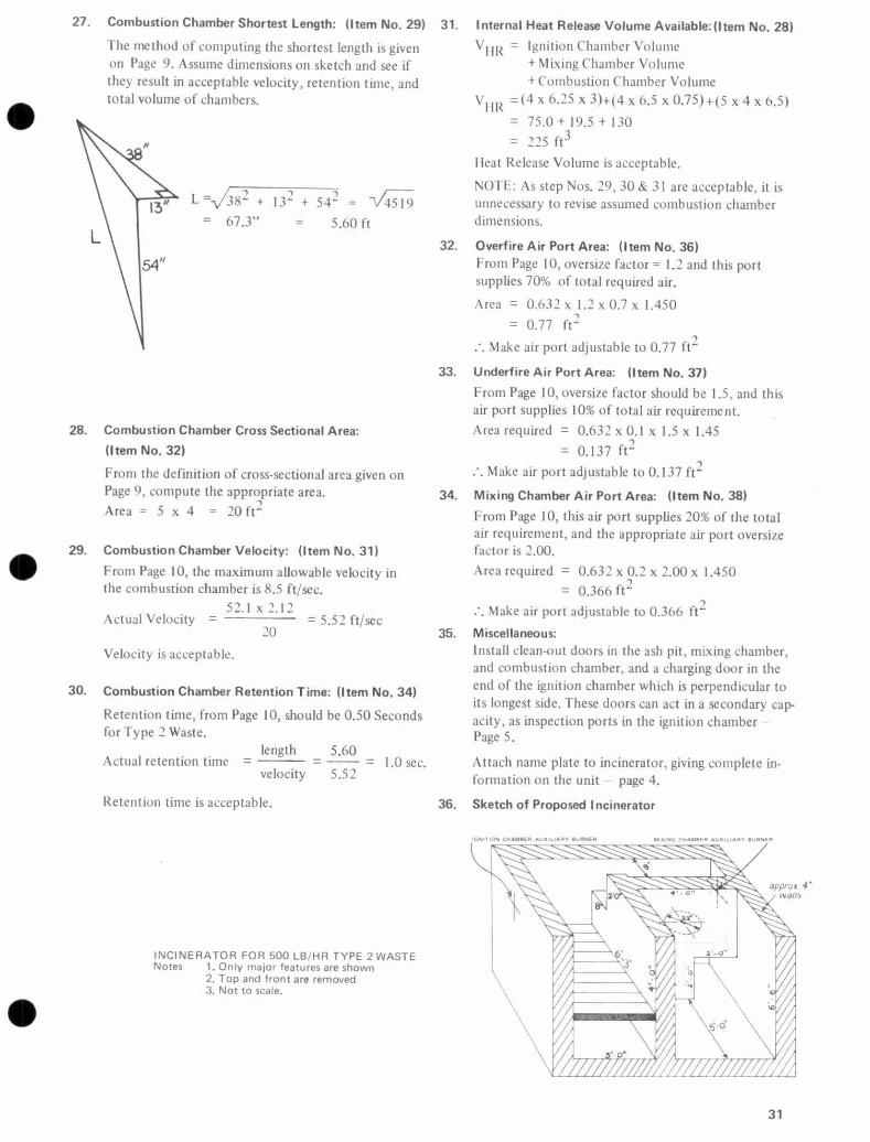
27. Combustion Chamber Shortest Length: (Item No. 29)
The method of computing the shortest length is given on Page 9. Assume dimensions on sketch and see if they result in acceptable velocity, retention time, and total volume of chambers.
L = 38' + 132
+ 542 = V4519 = 67.3" = 5.60 ft
28. Combustion Chamber Cross Sectional Area:
(Item No. 32)
From the definition of cross-sectional area given on Page 9, compute the appropriate area. Area= 5 x 4 = 20 ft`
29. Combustion Chamber Velocity: (Item No. 31)
I rom Page 10, the maximum allowable velocity in the combustion chamber is 8.5 ft/sec.
52.1 x 2.1'_ Actual Velocity = = 5.52 ft/sec
20
Velocity is acceptable.
30. Combustion Chamber Retention Time: (Item No. 34)
Retention time, from Page 10, should be 0.50 Seconds for Type 2 Waste.
Actual retention time = length
_ 5.60
= 1.0 sec. velocity 5.52
Retention time is acceptable.
31. Internal Heat Release Volume Available:(Item No. 28)
VIIR - Ignition Chamber Volume + Mixing Chamber Volume +Combustion Chamber Volume
V I I R
=(4x6.'_5x3)+(4 x6.5 x0.75)+(5x4x6.5) 75.0+19.5+130
= 225 ft3
Heat Release Volume is acceptable.
NOTE: As step Nos. 29, 30 & 31 are acceptable, it is
unnecessary to revise assumed combustion chamber dimensions.
32. Overf ire Air Port Area: (Item No. 36) From Page 10, oversize factor = 1.2 and this port supplies 70% of total required air.
Area = 0.632 x 1.2 x 0.7 x 1.450
= 0.77 ft2
Make air port adjustable to 0.77 ft`
33. Underf ire Air Port Area: (Item No. 37)
From Page 10, oversize factor should be 1.5, and this air port supplies 10% of total air requirement. Area required = 0.632 x 0.1 x 1.5 x 1.45
= 0.137 ft2
Hake airport adjustable to 0.137 ft2
34. Mixing Chamber Air Port Area: (Item No. 38)
From Page 10, this air port supplies 20% of the total air requirement, and the appropriate air port oversize factor is 2.00.
Area required = 0.632 x 0.2 x 2.00 x 1.450
= 0.366 ft` 2 Make air port adjustable to 0.366 ft`
35. Miscellaneous: Install clean-out doors in the ash pit, mixing chamber, and combustion chamber, and a charging door in the end of the ignition chamber which is perpendicular to its longest side. These doors can act in a secondary cap- acity, as inspection ports in the ignition chamber - Page 5.
Attach name plate to incinerator, giving complete in- formation on the unit page 4.
36. Sketch of Proposed Incinerator
approx. 4" Wdl/S
INCINERATOR FOR 500 LB/HR TYPE 2 WASTE Notes 1. Only major features are shown
2. Top and front are removed 3. Not to scale.
31

APPENDIX C3
INCINERATOR DESIGN EXAMPLE - NO. 3
OBJECT Design an incinerator for a 5,000 ft` supermarket.
PROCEDURE: The new "Incinerator Design Criteria" and the "Incinerator Design Check" were used as design aids. The following steps were taken to arrive at an acceptable design. Item numbers refer to items in the "Incinerator Design Check" and page numbers refer to the "Incinerator Design Criteria",
1. Capacity: Front Page 12, incinerators designed for supermarkets should be based on N lbs Type 3 waste per 100 ft' per day.
5000 Ib.waste day = x t) = 450 Ib/day
100
6.
7.
8.
9.
10.
11.
From page 12. the incinerator operating time could he up to 6 hoursAay. However, due to the fact that a 5,000 ft-' supermarket is a relatively small operation 12.
it would be desirable to operate for only I hour/day. T herefore, use a 400 Ib/hr incinerator for Type 3 waste, 13.
2. Type of Incinerator: Use an "in-line" type of incinerator as it would better 14.
suit the room available for it.
3. Grate Area: (Item No. 5 (a) )
Both the required nrinintum grate area and that area 5% larger than the minimum area are calculated and represent the lower and upper limits of allowable grate area.
4. Grate Length and Width: (Items No. 4, 2 & 3) From page 9, the ratio of grate length to width must equal 1.6.
Let x = grate width 1.6 x= grate length
then 1.6
x,-=
19.21 X2= 12.00 x = 3.47' or 3' 6"
& 1.6 x = 5.55'or5'6"
5. Arch Height: (Item No. 6)
Make arch height equal to 4' 0" as this falls within the allowable limits.
.ourgw
15.
16.
17.
18.
:d
,e
1f
Top of Charging Door: (Item No. 7) Make top of charging door 3' 0" above grate.
Ignition Chamber Auxiliary Burner: (Item No. 8) Make ignition chamber burner capacity equal to 1.'0 x 106 BTUrhr.
Mixing Chamber Auxiliary Burner: (Item No. 9) Make capacity equal to 1.' x 106 BTU hr.
Auxiliary Fuel: (Item No. 16) Use natural gas fuel as it is available on site of super- market.
Flame Port Area: (Item No. 24) Make flame port 12" high x 1_ wide,
Mixing Chamber Area: (Item No. 26) Make mixing chamber 42" long .x ')" wide.
Curtain Wall Port Area: (Item No. 27) Make curtain wall port 42" wide x 12" high.
Breech Size: (Item No. 30) Make Breech 20" in diameter.
Combustion Chamber Sizing. (Items No. 31, 32, 33, 34, 28) Make height of chamber equal to 60". Make width uf' charnber equal to 42".
Assume an inside length of 30" and go through items No. 31, 32, 33 and 34. Both velocity and retention time are unsuitable. Try inside length equal to 49". ('his time, velocity and retention time are acceptable, and item No. 28 is also acceptable.
Make inside chamber length = 48".
Overfire Air Port (Item No. 36) Make overfire air port adjustable to 72 in-.
Underfire Air Port: (Item No. 37)
Make underfire air port adjustable to 15 in,.
Mixing Chamber Air Port: (Item No. 38) 'Make mixing chamber air port adjustable to 45 in`.
Sketch of proposed 400lb/hrType 3 waste incinerator, showing main features. (Top and front removed, not to scale.)
.y E
32

APPENDIX C3
INCINERATOR DESIGN EXAMPLE-NO. 3 CONTINUED
APPENDIX: B : DESIGN ASSESSMENT
i
A QUICK REFERENCE GUIDE FOR ASSESSING INCINERATOR DESIGNS OF CONVENTIONAL THREE PASS TYPE INCINERATORS (Types 1, 2 and 3 wastes)
INCINERATOR DESIGN
ASSESSMENT
TYPE 3 WASTE
NO. ITEM AND CALCULATIONS NO. SUPPLIED
MEET AMB
CRITERIA COMMENT
1 RATED CAPACITY, Ibs waste/hr 1
11DO Ib/hr AID-D Ib/hr
2 IGNITION CHAMBER LENGTH, ft. in. 2 j. - (o " S' _ ( "
3 IGNITION CHAMBER WIDTH, ft. in. 3
4 RATIO IGN. CRAM. LENGTH TO WIDTH
3 ., Y2 1-6-7 i 6
5 GRATE AREA, (a) REQUIRED, 1- 0, + 5%)
TYPE 1 WASTE G.A. 1
_ - _ 13 LOG 1 13 x
yoo 1
TYPE 2 WASTE G.A. 10 LOG 1 10 x.2 (.OZ
1.
TYPE 3 WASTE G.A. 8 LOG 1 8x
GRATE AREA, (b) SUPPLIED
O x O V 144 144 i4 22 I12 ;zO.zO It
6 ARCH HEIGHT = 1.333 IG.A.)0.3636 ±
10%
LOG IA. H.) = 0.125 +0.3636 LOG ( O )
= 0.125 +0.3636 LOG I /q 2; )
= 0.125+0.3636x 1-25y = 0.125+ o HloI = 0 69R
A. H. = 3 91 ft( ± 10%1 3 6
A.H. RANGE = 3 52 ft - 11 30 ft to
OR = 3' - b" - y' -3" 6 y -D.. y.-j..
NOTE: Circled numbers refer to items as shown in left hand column, 33

NO. ITEM AND CALCULATIONS NO. SUPPLIED
MEET AMB
CRITERIA COMMENT
7 MAX. GIST, TOP OF CHARGING DOOR TO GRATE
= 0.75 (ARCH HEIGHT) =0.75 x O = 0.75 x 4 = 3 0D It
= 7 3'-0 3-0 8 IGNITION CHAMBER AUXILIARY BURNER
CAPACITY F x (LB. WASTE/HRI x BTU/hr
Ib waste/hr
= F x O x 01
= O 3'" x y00 x 6,000
c /20 _ 10 X /D BTU/hr 8 y /p4- BTU/hr BTU/hr
WHERE
F Q1
TYPE 1 WASTE 0 0
TYPE 2 WASTE 0.333 4,000
TYPE 3 WASTE 0.500 6,000
9 MIXING CHAMBER AUXILIARY BURNER
CAPACITY ? (1-F) x O x OM
= D .500 x y&D x k,"V / 2D /2D
BTU/hr 9 ! /O' BTU/hr BTU/hr V WHERE
(1-F) OM
TYPE 1 WASTE 1.000 1,000
TYPE 2 WASTE 0.667 4,000
TYPE 3 WASTE 0.500 6,000
10 TOTAL AVAILABLE AUXILIARY BURNER HEAT
GAB = 0.92 x ( O + O )
= 0.92 x (120x10`+/';Zv,1A 10
c 2 Z1k,1 6TU!hr = BTU/hr
11 NET AVAILABLE HEAT FROM WASTE
= tO x Ow = lD x 15-rD
6 O [o'D
b = 0 b0Y/0 BTU/hr 11 BTU/hr k/O
WHERE
TYPE 1 WASTE, QW = 5865
TYPE 2 WASTE, OW = 3418
TYPE 3 WASTE, QW = 1500
NOTE: Circled numbers refer to items as shown in left hand column.
r:
17J
34

NO. ITEM AND CALCULATIONS NO. SUPPLIED MEET AMB
CRITERIA COMMENT
12 TOTAL HEAT INTO INCINERATOR, OT
= 10 + 11 = 2' 81y/o" BTU/hr 12 2 SIY/OGBTU/hr
13 HEAT AVAILABLE FOR HEATING GASES,
ASSUMING ADEOUATE INSULATION IS PROVIDED
IN THE ABSENCE OF MORE ACCURATE DATA, ASSUME 5% OF TOTAL HEAT INPUT IS LOST
TO WALLS
HEAT AVAILABLE = 0.95 x 12
= 0.95 x 2. 1,elO = 2 & 71/04 BTU/hr 13 2" 61X/ObBTU/hr
14 FLOWRATE OF GASES THROUGH COMBUSTION
CHAMBER TO MAINTAIN TEMPERATURE OF
1600OF
=(D x 0.63 x 10-6
= 2 ro7 0.63 x 10- 6
_ b $ 2 Ib. gases 14 / ' 8 Z Ib/sec
sec.
15 RATE OF VOLATILIZATION OF WASTE
TYPE 1 WASTE. 0.90 = FRACTION VOLATILIZED
TYPE 2 WASTE 0.93 = "
TYPE 3 WASTE 0.95 =
FLOWRATE = F.V. x 1
3600
= p 45 x _ybo = O ! (o
Ib 15 p / O b Ib/sec
3600 sec.
16 AUXILIARY FUEL - NO. 201L > 19.600 BTU/Ib 16 -AJL,D'&D BTU/1b
NAT. GAS --->22,000 BTU/Ib
17 AIR FOR AUXILIARY FUEL - USE
14.0 Ibs air/lb No. 2 oil Ib air
17.0 lbs. air/Ib Nat. gas 17 , /7O
lb. fuel
18 FLOWRATE OF IGNITION CRAM. AUX. FUEL
_ O _ / a o x/O I. Ib = O fllSi 18 (7 015 /S Ib/sec
3600 x 16 3600 x 22, e"Z' sec
19 FLOWRATE OF MIXING CRAM. AUX. FUEL
O 6 _ /.;;C) X/O = or5i5 ro _ ,
3600 x 16 3600 x A 2, OV-0 sec 19 O a lS lS Ib/sec
NOTE Circled numbers refer to items as shown in left hand column,
35

NO. ITEM AND CALCULATIONS NO. SUPPLIED
MEET AMB
CRITERIA COMMENT
20 FLOWRATF OF AIR FOR IGN. CRAM. AUX. FUEL
(ASSUME 20"', E XCESS AIR, I E. FACTOR OF 1.21
- 1.? R 17 x 18
= 1,2x 17.0 x 0 0/SlS = 0-.30V Ib 20 O 309 Ib/sec
sec
21 F LOWRATE OF AIR FOR MIX. CRAM. AU X. FUEL
1ASSUME 2001. EXCESS AIR, I.E. FACTOR OF 1.2)
= 1.2 x 0-6 = 12 " l 7 D 0 O/f;-/S = 0 3Dq Ib 21 0 309 Ib/sec
sec
22 F LOWRATE OF AIR FOR WASTE COMBUSTION
_ 14 I
15 + 9, (3, 20 + 21 1
&82 ( 0 /0(.+0 oiS*OOii+O 30f+0.3091
_ 641 o O 42 $ Ib 22 p 92 S Ib/sec
sec
23 FLOWRATE OF GASES THROUGH FLAME PORT
= 10.8 X (D) + 15 + 18 + 20
= 10.8 x 0 90 ) + 0- t0!' + 0.016 + 0309
= 0-7y2 + 0'y?0 = /'/7Z Ib 23 Ib/sec
sec
24 FLAME PORT AREA (V= 551ps + 20%)
(a) REQUIRED AT 16000F
52.1 x 23 _ = 0.972 x 1'172
55
_ //y it2 1+ 200/61
110 SUPPL IF O = 12 x / = f 0 112
'?4
It2 p qr - 1-37 It2
144
25 TOTAL GROSS HEAT INPUT
QTG - O + O + (O x YVG)
=3 yX/fl` BTU/hr 25 3
TYPE OF WASTE 1 2 3
gNG 6500 4300 2500
NOTE: Circled numbers refer to items as shown in left hand column,
36

NO. ITEM AND CALCULATIONS NO. SUPPLIED MEET AMB
CRITERIA COMMENT
26 MIXING CHAMBER AREA IV - 35 rps #
20°%I
(J! REQUIRED AT 1600OF
52.1 x 14 - - b92 35
= 2 50 it2 1+ 20%)
Ib) SUPPLIED
= 9_x yz - 2'62 it2 26 / 144 z . 2 rte 2.0°-3 po rt2
l/
27 CURTAIN WALL PORT AREA (V =25 fps ±
20
(,i) REOLIMED AT 16"F
52.1 x 14
uti .
25
- 3'50 it2 1+ 20".,I
Ib) SUPPL IE D
yz . z = 3'so it2 27
144 3 50 1t2 2'$0 _ N'?0 ft2 V"
28 INCINERATOR INTERNAL VOLUME
INOT INCLUDING ASH PIT)
(a) RE OUIHED
25 3'Y xi0,
25,000 7x.000
- /3 it3
11,1 SUPPLIED
iGNITION V
CHAR1BE R 1728
72 O it3
%1IXING VM= q x &0 k y2
CHAMBE H 1728
13-1 rt3 COM
BUSTION - y8 (P 0 x /2 V C CHAMBER
1728
?0'0 it3
TOTAL VOLUME = VI + VM + VC
= 77.0 + / 3-1 + 7o 0
28
f 3 Y
tr3 - -o
3
NOTE: Circled numbers refer to items as shown in left hand column.
37

NO. ITEM AND CALCULATIONS NO. SUPPLIED
MEET AMS
CRITERIA COMMENT
29 DOWNPASS LENGTH (TOP IGN. CRAM. ARCH
TO TOP CURTAIN WALL PORT)
'o.8. ) = o.8xgM = 3 "0 It 29 qGD It ' 3-go It
30 STACK OR BREECH DIAM. (V 36 fps at 1200PFI
41,9 : 14 AREA REQ. __ _= 1.161 14
36
= 1.161 x N2
_ 1.0755' It2
DIAM., IN.. n 13.54 AREA. ft2 = 13.54 w 1-3d 30
_ /$ ly in. ZO in.diam Q #n,diam
31 COMBUSTION CHAMBER SHORTEST LENGTH
(DEFINED AS SHORTEST DISTANCE BETWEEN
EDGE OF CURTAIN WALL PORT AND EDGE OF
STACK OR BREECH)
Q F
2p1, -31
L ,gr
ro0"
0- =,o Tr y o . ya = fioz . y9 / ° = y. 0 9
o.
Q=;Z$
31 f7 " f t
NOTE: Circled numbws refer to items as shown in left hand column.
38

NO. ITEM AND CALCULATIONS NO. SUPPLIED
MEET AMS
CRITERIA COMMENT
32 COMBUSTION CHAMBER CROSS SECTIONAL
AREA IDEFINED AS BEING MOST NEARLY
PERPENDICULAR TO (3) S'{ r yz /y 0
_._$--PS It2 32 fy a
144 ft2
33 COMBUSTION CHAMBER VELOCITY
IV 8.5 fps) AT 1600OF
&-2b 52.1 x 14
V x / 6 8z = 9 t fps 33 6 z b 8.5 v N U fps fps
_ I
34 COMBUSTION CHAMBER RETENTION TIME
31 3 07q p711 secs 34 -sue sec 0 5 0 sec -
33 do 2 b
35 STACK OR BREECH LOCATION
O.K.or X MOVE FURTHER AWAY FROM
WALL PORT 35
36 OVERFIRE AIR PORT AREA
(a) REQUIRED
= 0.632 x 1.2 x 0.1 x 22
= 0.531 x 0 '22
= 0 41q3 It2
(bl SUPPLIED
?z 2 2
in = = 0 C ft 36
144 0 50 It2 O y q f12
37 UNDERFIRE AIR PORT AREA
(a) REQUIRED
0.632 x 0.1 x 39 x 22
= 0.0632 x / 72 x 0 42$ = 0 1 0 / It2
(b) SUPPLIED
'n2 _ 2 - = o oaf ft 7
144 /0 it2 0 '/lJ f12
38 MIXING CHAMBER AIR PORT AREA
(a) REQUIRED
0.632 x 0.2 . (9-0 = 0.1264 . 2 6 9 x p (?2j
= 0 3/3 It2
Ibl SUPPLIED
ys in2 - 0 3/z It2 =
144 38
0-31 It2 0.3/ ft2
NOTE: Circled numbers refer to items as shown in left hand column.
39

NO. ITEM AND CALCULATIONS NO. SUPPLIED
MEET AMB
CRITERIA COMMENT
39 OVERSIZE FACTORS
a
40 O 39 40
50 Ib/hr 250 5.00 39
, z 100 2.39 4.67 2 O 7
150 2.28 4.33 40
200 217 4.00
300 1 95 3.33
400 1.72 2.67
500 1.50 2.00
600 1.50 2.00
1000 1.50 2.00
41 IGNITION CHAMBER TEST OPENING 41 p P
42 i MIXING CHAMBER TEST OPENING Q.t1t 42
`/ L/ 43 COMBUSTION CHAMBER TEST OPENING
p zrt. 43
44 NAME PLATE X = NOT SHOWN
V = SHOWN 44
NOTE CNclad numbers rafw to rums as shown in loft hand column.
Pi
40

APPENDIX C 4
INCINERATOR DESIGN EXAMPLE - NO. 4
OBJECT: Design an incinerator to dispose of 100 Ib/hour of dead animal bodies.
SOLUTION:
STEP 1: Heat and Mass Balance
Composition (by weight) of Refuse: Dry Combustible 100 x 0.10 = 10 lb!hr Contained Moisture 100 x 0.85 = 85 Ib/hr Ash 100 x 0.05 = 5 Ib/hr
Total 100 Ib/hr
Gross Heat Input to Ignition Chamber: from waste 1,000 BTU/lb x 100 Ib/hr = 100,000 BTU/hr from auxiliary fuel 5,000 B fU/lb
x 100 Ib/hr = 500,000 BTU/hr
600,000 131U/hr
Heat Losses in Ignition Chamber;
(a) Radiation and Conduction I hrough Furnace Walls (use _'% of gross heat input)
600,000 x 0.02 = 12,000 BTU/hr
(h) 1vaporation of contained moistures at 600E (hfg = 1060 BI'U/lb) S5 Ib/hr of contained moisture 85 x 1060 = 90,100 BTU/hr
i; i Sensible Heat in Ash at 18000E
Cp = 0.217 BTU/lb o f 1800 -- 60 = 1740oF
(d)
M = 5.0 lb/hr of ash Q = M C'pLT Q = 5.0 x 0.217 x 1740 = 1,900 BTU/hr
Evaporation of water formed from combustion of dry combustible at 600E
10 Ib/hr of dry combustible (as cellulose) I Ib of cellulose yields 0.556 Ib of water (hfg = 1060 BTU/lb at 600F) 10 x 0.556 x 1060 = 5,900 BTU/hr
(e) Evaporation of water formed from combustion of natural gas. 500,000 BTU/hr of Nat. gas at 1,000 BTU/SCF I SCF Nat. gas produces 0.099 Ib of water (hfg = 1060 BTU/lb at 60oF) 500,000
x 0.099 x 1060 = 52,500 BTU/hr 1,000
Total Heat Loss in Ignition Chamber =162,400 BTU/hr
or ?7.1% of Gross Heat Input.
Heat Available to Raise Temperature of Products of Combustion to 1800OF:
Gross Heat input Heat Losses
= 600,000 162,400 =437,600 BTU/hr
Required Weight of Products of Combustion in the Ignition Chamber to Maintain 18000E
Weight of gases from: M= Q
Cp Ot
Where: Q = 437,600 BTU/hr C'p = 0'9 BTU/lb OF (Assumed Average
Value)
0._'9 x 1740
pt = 1800 60 = 1740OF
437,600 M = = 868 pounds/hour of
products of combustion
Required Excess Air in Ignition Chamber to Maintain 1800oF Weight of gases from: (a) Natural Gas 20% excess air assumed
I SCF Nat. gas- 0.999 Ih of products of combustion 500 SCF/hour of Natural gas required. 0.999 x 500 = 500 Ib/hr
(b) Contained Moisture 85 Ib/hour of moisture = 85 Ib/hr
(c) Dry Combustible (Assumed as ('cllUlose) 10 Ib/hr or dry combustible I lb of cellulose requires 5.08 lb of air let Xs = percent excess air
10[(I+5.08)+ x5.081 60.8+0.508Xs 100 1
Total weight of gases - M =645,8 +
868 = 645.8 + 0.508 Xs
0.508 Xs
2-12.2 Xs 0.505 = 438% excess air for cellulose
Volume of Combustion Gases in Ignition Chamber (a) From Dry Combustible only = 10 lb./hr at 600E
Qt =
Ib/hr of Cellulose 600E 3600
78.2 + 10 x 663) ]cfs at 600F
10 438 1
78? +(-x 66.3) - 1.021 cfs at 600F 3600 11100
(b) From Natural Gas Only (500 ('FII at 20% excess air)
Qt = 60" -
x110.76+ Xs x 9.7'
111
) J 100
SCFH of Natural Gas
3600
'0 1
.731 10.76 + (100 - x 9 360
41

(c) From Contained Moisture only (85 Ib/hour) density at 60OF = _' 1.1 f13/lb of water
85 x 21.1 = 0.498 cfs at 600F
I - b 1- 3600
Total Volume of Gases at 60OF = 3.281 cfs at 60oF 2260
Volume at 1800OF = 3.281 x = 14.24 cfs at 5_ 1800OF
Flowrate of Gases in Ignition Chamber:
_ 14.24 cfs at 1800"F per 100 lb/hour of waste (** See later)
Required Secondary Burner Input: 3000 BTU 3000 BTU/pound are required by Criteria 100 pounds/hour of Waste Burner should be 300,000 BTU/hour capacity or
300 CFH of Natural Gas
Heat Available to Maintain Gases at 1800OF:
(a) Loss Due to Radiation & Conduction through furnace Walls (Use 2% of Burner input) 300,000 x 0.02 = 6,000 BTU/hour
(b) Loss Due to Evaporation of Water formed from Combustion of Natural Gas (lifg = 1060 BTU/Ib at 60OF
300 x 00)9 x 1060 = 31,500 BTU/hour Total Losses = 37,500 BTU/hour
(c) Net Heat Available = Gross Heat Input Losses
= 300,000 37,500 = 262,500 B"1 U/hour
Required Weight of Products of Combustion: after the secondary burner to Maintain 1800oF
Q M =
CPL t
Q = 262,500 Cp = 0.25 BTU/lb - of (assumed)
I = 1800 - 60 = 1740OF
262,500 M= = 604 lb/hr of products of
0.25 x 1740 combustion
The natural gas using 20% excess air (300 CFH natural gas) produces 300 Ib/hour of gases.
604 - 300 = 304 lb/hour of excess air is required. 10 lb/hour of combustible require 50.4 Ib/hour of air theoretically. 304
= 603% excess air must be added in the 50.4 secondary burner.
Total excess air used for dry Combustible in waste = 603 + 438 = 1041 %
The 604 Ib/hour of products of combustion has an
average molecular weight very nearly that of air.
Specific volume of air at 1800OF = 56.95 ft3/lb
Volume of gases added by secondary burner 604 x 56.95
= 9.55 cfs at 1800oF 36(x)
Total Volume of Gases after Secondary Burner: 14.24 + 9.55 = 25.714 cfs at 1800" l:
per 100 lb/hr of waste **(14._24 from earlier)
STEP 11: Sizing of Incinerator Chambers and Ports
A. IGNITION CHAMBER: Hearth Area at 10 Ibs/hour per sq. ft.
100 Area = - = 10 square feet
10
Length ratio =
Width
Width
L = 2W
Area = _'W.W = 10 ft2 W = 2.237 ft L = 4.474 ft
Length
_ ,, 2-7/8"
= 4' - 5-5/8"
Arch Height (average) from figure 6 of criteria ,6
= 2.17 feet
Ignition Chamber Volume 10.0 x _'.17 = 21.7 ft3
B. FLAME PORT AND MIXING CHAMBER:
Velocity Required 20 fps ± 20%
Volume of Gases = 14.24 cfs at 1800OF (see ** earlier)
14.24 Area Required = =
'0 0.712 ft`
C.
D.
PORT AT BOTTOM OF MIXING CHAMBER:
Velocity Required 20 fps
Volume of gases = 23.79 cfs at 1800OF (see ** earlier)
Area Required 23.79
= = 1.190 ft2 _'0
CHAMBER BELOW HEARTH:
Velocity Required = 10 fps ± 100%
Volume of gases = 23.79 cfs at 1800OF
23.79 , Area Required= _ 2.38 ft`
10
E
42

C
E. PORT AT BOTTOM OF COMBUSTION CHAMBER:
Velocity Required = 20 fps + 20% at 1800OF
Volume of gases = 23.70 efs at 1800OF
23.79 Area Required = = 1.190 ft`
20
F. COMBUSTION CHAMBER:
Velocity Required = 5 fps ± 100% at 1800OF
Volume of gases = 23.79 fps
23.79 , Area Required = = 4.76 ft-
5
G. STACK:
Velocity Required = 33 fps at 1600oF
_'060 Volume of gases = 23.79 x - = 21.7 efs at
2260 1600OF
21.7 Area Required = - = 0.657 ft2
33
112 Diameter Required = ( r4 x 0.657 = 0.015 feet
or approximately 1 I" diameter.
43

APPENDIX D : GUIDES TO APPLICANTS
FOR CERTIFICATES OF APPROVAL
. All new incinerators and changes. modifications or addi- tions to existing ones. requires a Certificate of Approval from the Ministry of the Environment. Applications are to be submitted to the Environmental Approvals Branch of the Ministry.
_'. Normally the owner is considered to be responsible for obtaining approval, however, this responsibility may be delegated to consultants, suppliers or installers.
3. Application Form No. 3 "Incinerator" should be used. These forms are available from the Environmental App- rovals Branch of the Ministn of the Environment.
4. All the data requested on the form should be supplied, or if not applicable to the specific project, this should be indicated.
5. In addition to the drawings or blueprints indicated in the box on Page 3 of the form, it is usually necessary to in- clude drawings or sketches of - (a) Incinerator room lay-out with dimensions showing air intakes and other equipment in the same room.
(b) The building. in which the incinerator is to be sited, showing the location of the chinmey or stack and its re- lationship to other roof structures. air intakes, windows. balconies and neighbouring buildings.
6. When master drawings are on file with the Branch. it may not be necessary to include detailed incinerator drawings with each application. Similarly it is not necessan to sub- mit a heat balance with every application, though this will be required with the first application involving a new design, and for incinerator for types 5 and 6 wastes.
7. Material balances (or lists of materials to be burnt) are usually required for incinerators for types 5 and 6 wastes.
S. When in doubt about any matter. it would be advisable to contact one of the engineers in the Approvals Section of the Branch.
In assessing applications for Certificates of Approval, the Environmental Approvals Branch will use these criteria as guides in judging the acceptability. Deviations front these criteria may, result in rejection of the design, however. each application will he judged un its merits and variations which do not adversely affect performance will not result in rejection.
44