design and operation maintenance on dc power system
TRANSCRIPT

Design and Operation Maintenance on DC Power System
Ning Li1, Jincheng Yang1, Li Wang1, Dongdong Huang1, Xiaoyan Zhao2,
Yidi Zhang2 1Xinjiang Institute of State Grid Electric Power Research, Wulumuqi, 830000, China.
2Yantai Power Supply Company of State Grid Shandong, Yantai 264000, China.
Abstract. Based on specific products and actual projects, the DC system of the substation is designed, and the principles and functions of each component module of the DC system are described. The grounding line determines whether the lightning protection system can work safely and reliably. Taking lightning protection as an example, the DC system lightning protection system is designed according to the lightning arrester installation method and the related technical requirements for grounding in the lightning protection system design. Taking the DF0210A intelligent high-frequency switch DC operating power supply system as an example, the operation and maintenance of the DC power supply system is described.
Keywords: DC system, Lightning protection system, Operation and maintenance.
1. Introduction
DC is an important equipment of the power system. Its performance and quality are directly related to the stable operation of the power grid and equipment safety. The DC power system is the power supply for circuit breakers, closing and closing operations and DC pumps. The system is the relay protection, the working power of the automatic device, the power source indicated by the signal, and the backup power source during the fault condition. DC power is provided for control devices, automation devices, relay protection devices, high-voltage circuit-breaker switching mechanisms, and accident lighting loads. The DC operating power system composed of valve-regulated lead-acid battery packs has strong reliability and high stability, and its reliability directly affects the safe operation of power plants and substation equipment.
With the automation of power dispatch and the development of relay protection equipment, the degree of automation of the power system is getting higher and higher, and power plants and substations are gradually becoming unattended. The operation of all switching devices and relay protection devices are controlled automatically or remotely. Once the DC system fails, it may cause major accidents and the status of the DC system in the equipment becomes more and more important. Customers have put forward higher requirements on the high reliability, high intelligence, maintenance-free performance of the power supply products and on-line upgrade of the products, which has become an inevitable trend of development of power supply products.
2. General Design of Substation DC Power System
DF0210A intelligent DC operating power system is mainly composed of high frequency switching power supply charging device, monitoring unit, pressure reducing device, insulation device and power distribution system. The system block diagram shown in Figure 1.
The input of the DC system can be one or two AC power sources. One AC input is the main power supply, and the other AC input is the backup power supply. When the main power fails, the AC automatic switching device can automatically switch to the standby power supply. The charging device consists of different specifications of high-frequency switching power supply modules. For example, DF0231-220V/5A, DF0231-220V/10A or DF0233-220V/30A, etc.
20Copyright © 2018, the Authors. Published by Atlantis Press. This is an open access article under the CC BY-NC license (http://creativecommons.org/licenses/by-nc/4.0/).
2nd International Conference on Material Science, Energy and Environmental Engineering (MSEEE 2018)Advances in Engineering Research (AER), volume 169

Fig. 1 Block Diagram of DF0210A DC System
According to the needs of the site, the high-frequency switching power supply module can be
single-hung on the closing bus or divided into two groups. The output of a group of modules is directly connected to the closing bus for charging or floating charging of the battery pack. The output of another group of modules is directly connected to the control bus to provide normal load power supply for the control bus.
When the AC power is normal, the voltages of the closing bus and the control bus are provided by the rectifier module. The voltage-reducing device between them is in the cut-off state by the reverse voltage, no current passes, and is in standby state. When the AC power source fails, the reverse voltage received by the voltage-relief device disappears, the voltage-reducing device automatically resumes conduction, and the battery pack supplies power to the control bus through the voltage-reducing device.
The system-configured insulation monitoring device is used to monitor the insulation status of the DC system and the load. When the insulation resistance of the system to ground is less than the set value, an alarm message is issued to prevent accidental accidents and misoperation of the microcomputer protection device caused by grounding.
The monitoring unit mainly collects information about the DC system. Such as AC input voltage, rectifier module output current, battery charge and discharge current, control bus voltage, battery voltage, and ambient temperature around the battery. According to the collected information, the control rectifier module realizes conversion between different charging modes of the battery and temperature compensation under the floating charging mode. At the same time, remote control functions are realized through serial communication.
3. Substation DC Power System Configuration
The substation DC power system consists of a charging screen, a feed screen, and a battery screen. The specific structure is shown in Table 1.
From an electrical point of view, it is composed of electrical units such as charging equipment, batteries, integrated monitoring equipment, pressure regulating devices, in and out feeder circuits, insulation monitoring, and signal indication circuits. 110kV substation DC system rated voltage 220V. In the normal float charge mode of the battery pack, the DC bus voltage should be 105% of the rated voltage of the DC system.
21
Advances in Engineering Research (AER), volume 169

Table 1. Typical DC Power System Configuration
Charging screen
High-frequency switching power supply module
Microcomputer monitoring unit
AC automatic switching device
AC side lightning arrester
Feeder screen
Insulation monitoring device
Automatic pressure regulator
DC output circuit breaker
Battery screen Battery
Battery Tester
The rectifier adopts DF0231-220/10 high-frequency switching power supply rectifier module. The
AC input voltage first passes through the EMI power supply filter circuit to eliminate mutual interference between the power grid and the power supply module. In order to eliminate the impact on the grid when the power module is turned on, a soft-start circuit is also added in the AC section. After bridge rectification, alternating current is converted into 100Hz ripple DC. Then, the boost circuit boosts the pulsating DC voltage and filters it to a DC voltage of about 400V.
In order to increase the power factor of the power module, the control circuit uses a UC3854-specific control chip. By detecting the instantaneous voltage and current of the pulsating DC, the on and off times of the switch tube are controlled. Make the input current of the power module in phase with the input voltage. The rectifier module has a power factor of more than 96%.
The use of an active power factor correction circuit not only eliminates harmonic pollution to the power grid and interference with other surrounding electronic equipment, but also broadens the AC input voltage range of the power module.
The rear DC-DC section uses a half-bridge high-frequency converter. The two-phase pulse control signal with a phase difference of 180 degrees respectively triggers the corresponding high-frequency switch tube. The 400V DC voltage is converted into a pulsating DC output.
DF0241 touch screen power monitoring system, with "telemetry, remote signaling, remote control, remote adjustment" four remote functions. Telemetry is the acquisition and display of analog voltages such as AC voltage, AC current, DC voltage, and current. Remote signaling is the correct acquisition and display of the switch. Remote control means that monitoring can correctly transform the system status to ensure that the battery can be properly maintained. The remote adjustment means that the system's mother voltage can be changed according to the system settings. The monitoring unit can meet the requirements of power plant automation and unattended substations for power systems. Equipped with a standard RS232/RS485/RS422 interface for easy integration into power station automation systems.
DF0241 touch screen power monitoring system is divided into two types: centralized monitoring unit and distributed monitoring unit. The distributed power monitoring system mainly includes the main monitor, YL-JK02 monitoring unit, YL-JZ01 AC and DC information acquisition unit and YL-YX01 remote signal acquisition unit. Each department communicates with the main monitor via the 485 bus.
DC power equipment used in substations should have fully automatic functions. For example, the automatic conversion of charging mode, temperature compensation, charging machine self-injection, automatic pressure regulation, operation status monitoring and so on. Microcomputer monitoring unit can be used to achieve automatic conversion of battery charging procedures and insulation monitoring of DC systems.
22
Advances in Engineering Research (AER), volume 169
Mainly include: 1. It should be able to provide the main station with various signals of the DC power supply or the
complete set of equipment operating conditions. (1) Operating status: Charging or floating charge (2) Bus operation status: closing and controlling the bus voltage (3) Battery Pack Operation: Terminal Voltage, Float Current, Temperature (4) Important feeder fuse or air switch status (5) DC system insulation status 2. It should be able to provide the main station with multiple monitoring and alarm signals for
product operation. For example, rectifier failures, over-current protection, fuse blowing in important locations, and tripping of air switches, bus voltage monitoring, insulation monitoring, battery terminal voltage anomalies, and float current abnormality alarms.
3. Various measurement results and various monitoring and alarm signals should be able to be stored or checked through the printer output.
4. should have a communication interface to achieve telemetry, remote signaling, remote control, remote adjustment function.
5. Passwords should be set through the use of a keyboard or other device to allow professionals to set specific parameters.
4. Safety Grounding and Lightning Protection Technology
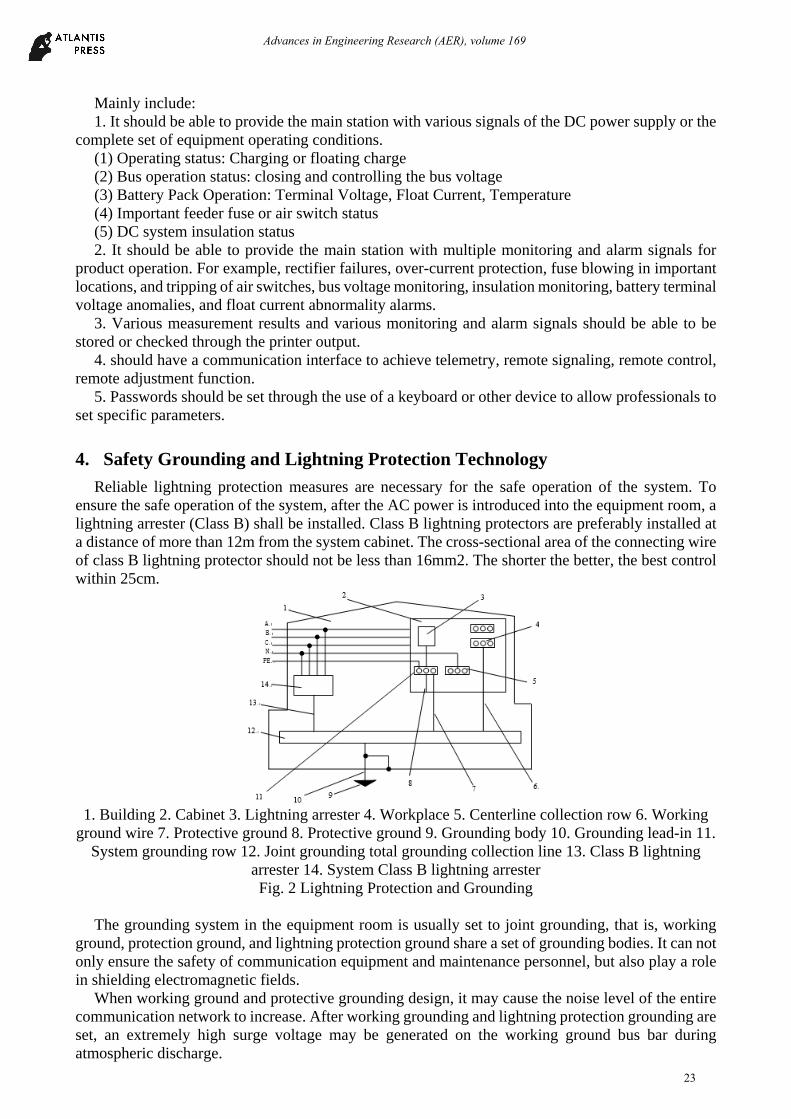
Reliable lightning protection measures are necessary for the safe operation of the system. To ensure the safe operation of the system, after the AC power is introduced into the equipment room, a lightning arrester (Class B) shall be installed. Class B lightning protectors are preferably installed at a distance of more than 12m from the system cabinet. The cross-sectional area of the connecting wire of class B lightning protector should not be less than 16mm2. The shorter the better, the best control within 25cm.
1. Building 2. Cabinet 3. Lightning arrester 4. Workplace 5. Centerline collection row 6. Working
ground wire 7. Protective ground 8. Protective ground 9. Grounding body 10. Grounding lead-in 11. System grounding row 12. Joint grounding total grounding collection line 13. Class B lightning
arrester 14. System Class B lightning arrester Fig. 2 Lightning Protection and Grounding
The grounding system in the equipment room is usually set to joint grounding, that is, working
ground, protection ground, and lightning protection ground share a set of grounding bodies. It can not only ensure the safety of communication equipment and maintenance personnel, but also play a role in shielding electromagnetic fields.
When working ground and protective grounding design, it may cause the noise level of the entire communication network to increase. After working grounding and lightning protection grounding are set, an extremely high surge voltage may be generated on the working ground bus bar during atmospheric discharge.
23
Advances in Engineering Research (AER), volume 169

The complex ground of the AC neutral line must not share the ground line or ground network with the equipment, and the ground line should be buried separately. Before connecting to the AC power distribution cabinet, connect the neutral cable to the cabinet with the neutral wire. The protective grounding wire in the three-phase five-wire system and the single-phase three-wire system can be directly connected to the grounding bar of the power system or connected to the protective ground connection of the AC power distribution screen.
The working ground and protective earth connection lines should not be connected in any way at the equipment rack end, but should be connected to the joint grounded total grounding collection line by category. The distance between the working site and the lightning protection point on the joint grounding total grounding collection line should be no less than 5m, and when the conditions permit, the distance should be 10m to 15m or more. The joint grounding total grounding collection line is then connected to the grounding body using single or multi-point grounding.
5. 110KV Substation Actual Engineering Design
The program uses the DF0210A intelligent high-frequency switch DC operating power system, designed in accordance with the N+1 redundancy backup and "unattended" principle. The system is configured specifically for 2 screens: DF0210A is charged with 1 screen and DF0210A with 1 screen. The detailed system configuration table is shown in Table 2.
Table 2. Detailed System Configuration
product name specifications quantity
DC operating power DF0210A feed screen 1
DC operating power DF0210A battery screen 1
Rectifier module DF0231-220/10 3
Monitoring unit DF0241-JC-DL 1
Grounding inspection instrument SD-JD01 1
Equipment operating conditions: (1). The altitude does not exceed 2500m; (2). The ambient air temperature during operation of the
equipment is not higher than 55°C and not lower than -15°C; (3). The daily average relative humidity is not more than 95%, and the monthly average relative humidity is not more than 90%; (4). There is no strong vibration and impact during installation and use, no strong electromagnetic interference, and the external magnetic field induction intensity must not exceed 0.5mT; (5). Installation vertical inclination does not exceed 5%; (6). There must be no dangerous medium for explosion in the place of use. The surrounding medium does not contain harmful gases and conductive media that can cause corrosion of metals and damage to insulation. Moulds are not allowed to exist. (7). Earthquake resistance: horizontal ground acceleration: 0.3g, ground vertical acceleration: 0.15g, and the role of continuous three sine waves, safety factor 1.67.
Device input features: (1). AC three-phase four-wire, no phase sequence requirements; (2). AC input voltage: 2 × 380V
± 30%; (3). Enter the grid frequency: 45 ~ 55Hz; (4). Efficiency: ≥ 90%; (5). Power factor: ≥0.99. Equipment mechanical properties: (1). Cabinet size (height × width × depth): 2260 × 800 × 600mm; (2). Dustproof: closed air duct
design, heat dissipation surface and components completely isolated; (3). Heat dissipation: self-cooling and temperature-controlled air-cooling; (4). Acoustic noise: ≤ 50dB (A); (5). Color: computer gray Z32 (Flying Tiger card); (6). Signals, lights using new energy-saving lamps; (7). DC circuit breaker: with auxiliary contacts, with the corresponding arc extinguishing ability.
24
Advances in Engineering Research (AER), volume 169

Device output characteristics: (1). DC rated output voltage: 220V; (2). Control bus voltage: 220V ± 5%; (3). Closing bus voltage:
220V ~ 286V; (4). regulator accuracy: ≤ ± 0.5%; (5). Steady flow accuracy: ≤ ±0.5%; (6).The average flow imbalance: ≤ ± 3%; (7). Ripple factor: ≤ 0.1%; (8). Acoustic noise: ≤ 50dB; (9). Pressure regulating device: The pressure regulating device configured for the DC system is a graded automatic silicon chain pressure reducing device. The device has two automatic and manual pressure regulators. With high reliability, stable performance and other characteristics. In the automatic mode, the internal control circuit detects the voltage of the control bus in real time. When the value exceeds the rated voltage range, the number of automatically controlled silicon chains reaches the purpose of voltage regulation. Since the voltage regulation range of each stage is 5V, its voltage regulation accuracy can reach 2.5%. (10). DC out-feed protection: The DC system adopts a fast DC circuit breaker with an auxiliary contact at the battery access and DC feed-out circuit, because the DC circuit breaker uses a DC thermal electromagnetic over-current release. Its breaking speed, high conversion ability, can play the most reasonable protection against short circuit faults. When the switch trips, the monitoring unit can immediately upload this information to the master monitoring system.
6. Summary
Combine the actual project, build the direct current system. Using temperature-controlled air-cooling and duct isolation technology, the average time between failures is greatly improved, and dust deposition inside the module is effectively prevented, which improves reliability. Increase reliable lightning protection and electrical insulation protection measures to ensure system and personal safety. Smoothly regulates output voltage and has automatic battery temperature compensation. With multiple expansion serial ports, access to a variety of external smart devices. With four remote functions, it can communicate with intelligent devices such as integrated automation systems to meet the needs of unattended substations.
References
[1]. Ibraheem, Nizamuddin, T.S. Bhatti. AGC of two area power system interconnected by AC/DC links with diverse sources in each area, International Journal of Electrical Power and Energy Systems, 2014, 15(2):617-620.
[2]. Yuqi Wang, Qingshan Xu, Mengjia Liu, Jiaqi Zheng. A novel system operation mode with flexible bus type selection method in DC power systems, International Journal of Electrical Power and Energy Systems, 2017, 30 (12):634-644.
[3]. Vahid Dargahi; Arash Khoshkbar Sadigh; Mohammad Reza Alizade. DC (direct current) voltage source reduction in stacked multicell converter based energy systems, IEnergy, 2012, 11 (5):222-227.
[4]. Grebenyuk G.,Solov’ev M. Continuous Price Regulation to Form the Desired Load Schedule of a Power System, Automation & Remote Control,2004,65(5):834-839.
[5]. Kosykh, A.V, Ionov, B.P. Dynamic temperature model and dynamic temperature compensation of crystal oscillators. IEEE transaction on ultrasonics, ferroelectrics, and frequency control, 2005, 41(3):370-374.
[6]. Suresh Singh; Aditya R. Gautam; Deepak Fulwani. Constant power loads and their effects in DC distributed power systems: A review, Renewable and Sustainable Energy Reviews, 2017, 15 (5):756-764.
25
Advances in Engineering Research (AER), volume 169