design and optimization of anti-roll bar
TRANSCRIPT
Kaunas University of Technology
Faculty of Mechanical Engineering and Design
Design and Optimization of Anti-Roll Bar
Master’s Final Degree Project
Amalraj Palraj Palraj Mariappa
Project author
Assoc. Prof. Dr. Lukoševičius Vaidas
Supervisor
Kaunas, 2018
Kaunas University of Technology
Faculty of Mechanical Engineering and Design
Design and Optimization of Anti-roll Bar
Master’s Final Degree Project
Vehicle Engineering (621E20001)
Amalraj Palraj Palraj Mariappa
Project author
Assoc. Prof.Dr. Lukoševičius Vaidas
Supervisor
Assoc. Prof. Artūras Keršys
Reviewer
Kaunas, 2018
Kaunas University of Technology
Faculty of Mechanical Engineering and Design
Amalraj Palraj Palraj Mariappa
Design and Optimization of Anti-roll Bar
Declaration of Academic Integrity
I confirm that the final project of mine, Amalraj Palraj, Palraj Mariappa, on the topic „Design and
Optimization of Anti-roll Bar “is written completely by myself; all the provided data and research
results are correct and have been obtained honestly. None of the parts of this thesis has been
plagiarised from any printed, Internet-based or otherwise recorded sources. All direct and indirect
quotations from external resources are indicated in the list of references. No monetary funds (unless
required by law) have been paid to anyone for any contribution to this project.
I fully and completely understand that any discovery of any manifestations/case/facts of dishonesty
inevitably results in me incurring a penalty according to the procedure(s) effective at Kaunas
University of Technology.
(name and surname filled in by hand) (signature)

KAUNAS UNIVERSITY OF TECHNOLOGY
FACULTY OF MECHANICAL ENGINEERING AND DESIGN
Study programme VEHICLE ENGINEERING (621E20001)
TASK ASSIGNMENT FOR FINAL DEGREE PROJECT OF
MASTER STUDIES Given to the student: Amalraj Palraj Palraj Mariappa
1. Title of the Project:
Design and Optimization of Anti-roll Bar
Stabilizatoriaus Projektavimas Ir Optimizavimas
2. Aim and Tasks of the Project
To examine which measure the durability of the Anti-roll Bar on rotation and vertical displacement
Tasks:
1. To perform the literature review
2. Compare the stiffness of the various dimensions of the anti-roll bar, which will be made of spring
steel
3. Perform an anti-roll bar analysis ANSYS Workbench and ANSYS parametric design language
program
4. Assess how the displacement depends on the size of the forces and the dimensions of the anti-
roll bar
5. Check the stresses and vertical displacements of the designed composite anti-roll bar
2. Initial Data:
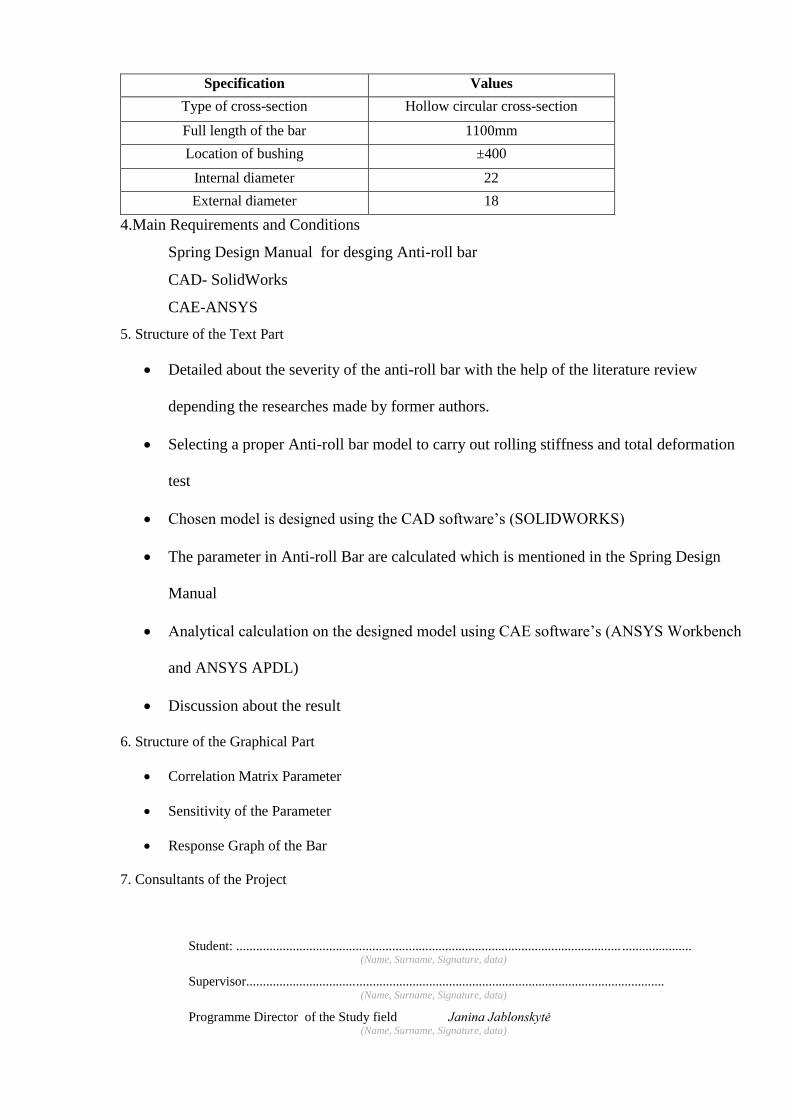
Specification Values
Type of cross-section Hollow circular cross-section
Full length of the bar 1100mm
Location of bushing ±400
Internal diameter 22
External diameter 18
4.Main Requirements and Conditions
Spring Design Manual for desging Anti-roll bar
CAD- SolidWorks
CAE-ANSYS
5. Structure of the Text Part
• Detailed about the severity of the anti-roll bar with the help of the literature review
depending the researches made by former authors.
• Selecting a proper Anti-roll bar model to carry out rolling stiffness and total deformation
test
• Chosen model is designed using the CAD software’s (SOLIDWORKS)
• The parameter in Anti-roll Bar are calculated which is mentioned in the Spring Design
Manual
• Analytical calculation on the designed model using CAE software’s (ANSYS Workbench
and ANSYS APDL)
• Discussion about the result
6. Structure of the Graphical Part
• Correlation Matrix Parameter
• Sensitivity of the Parameter
• Response Graph of the Bar
7. Consultants of the Project
Student: .................................................................................................................... ..................... (Name, Surname, Signature, data)
Supervisor.............................................................................................................................. (Name, Surname, Signature, data)
Programme Director of the Study field Janina Jablonskytė (Name, Surname, Signature, data)

6
Table of Contents Chapter-1………………………………………………………………………………………13
Introduction……………………………………………………………………………………13
1.1 Introduction to Anti-roll Bar……………………………………………………………..13
1.2 Postulate of Anti-roll Bar………………………………………………………………14
1.3 Basic geometry of Anti-Roll Bar……………………………………………………….14
1.3.1 Geometry…………………………………………………………………………..14
1.3.2 Materials…………………………………………………………………………...15
1.3.3 Connection…………………………………………………………………………15
1.3.4 Bushing…………………………………………………………………………….15
1.3.5 Fixtures used to Suspension Members……………………………………………..16
1.4 Detachable stabilizers………………………………………………………………………17
Chapter-2………………………………………………………………………………………..18
Literature Review………………………………………………………………………………18
Chapter-3………………………………………………………………………………………..22
Theoretical Background………………………………………………………………………..22
3.1 Determination and Function………………………………………………………….22
3.2 Principle Function of Anti-Roll Bar………………………………………………….23
3.3 Problem Statement…………………………………………………………………...24
3.3.1 Inactive in vehicle handling………………………………………………...24
3.3.2 Rattling Under the chassis of the car………………………………………..24
3.3.3 Squeaking Sound from under the vehicle…………………………………...25
3.4 Type of Suspension System………………………………………………………….25
3.4.1 McPherson’s Suspension……………………………………………….…..25
3.4.2 The double hinge Suspension………………………………………………26
3.4.3 Dependent hinge Suspension……………………………………………….26
3.4.4 Independent Suspension……………………………………………………26
3.5 Anti-roll bar Position…………………………………………………………………26
3.6 The effect of the Anti-roll bar on comfort…………………………………………….28
3.7 Audi R8 Anti-roll bar…………………………………………………………………28

7
Chapter-4………………………………………………………………………………………..30
Methodology…………………………………………………………………………………….30
4.1 Investigation Method…………………………………………………………………30
4.2 Material………………………………………………………………………………31
4.2.1 Introduction to Structural Steel…………………………………………….31
4.3 CAE Tool…………………………………………………………………………….32
4.3.1 System Analysis……………………………………………………………32
4.3.2 Ansys Simulation.………………………………………………………….32
4.4 Model Description……………………………………………………………………33
4.5 SOLIDWORKS Model………………………………………………………………33
4.6 Response Surface Optimization………………………………………………………34
Chapter-5………………………………………………………………………………………..35
Calculation of Anti-roll Bar…………………………………………………………………….35
5.1 Diameter Calculations………………………………………………………………..37
5.2 Analytical method……………………………………………………………………37
5.3 Numerical Analysis in ANSYS………………………………………………………38
5.4 Model Setup………………………………………………………………………….38
5.4.1 Remote Displacement………………………………………………………39
5.4.2 Connection…………………………………………………………………40
5.4.3 Load………………………………………………………………………...40
5.5 Meshing………………………………………………………………………………41
Chapter-6………………………………………………………………………………………..42
Result and Discussion…………………………………………………………………………..42
6.1 Analysis of Anti-roll in Finite element analysis result………………………………42
6.1.1 Total Deformation………………………………………………………….42
6.1.2 Equivalent Stress…………………………………………………………...43
6.2 Analyses Numerical Analysis with APDL……………………………………………43
6.3 Parameter correlations for Anti-roll bar………………………………………………47
6.4 Response Surface Optimization………………………………………………………49
Conclusion………………………………………………………………………………………52
Reference………………………………………………………………………………………..53

8
Appendices………………………………………………………………………………………55
Appendixes 1…………………………………………………………………………….55
Appendixes 2…………………………………………………………………………….62
9
List of Figure
Figure 1.1 Anti-roll Bar…………………………………………………………………………14
Figure.1.2 Two-Sample Part Anti-Roll Bar…………………………………………………….15
Figure.1.3 Bushing (rubber bushings and metal mounting blocks)…………………………..…16
Figure.1.4 Pin Joint……………………………………………………………………………...16
Figure.3.1 SUV…………………………………………………………………………………..23
Figure.3.2 various type anti-roll bar connection………………………………………………….27
Figure.3.3 Anti-roll Bar………………………………………………………………………......28
Figure.3.4 Anti-roll bar Audi R8 …………………………………………………………………29
Figure.4.1 Investigation Method…………………………………………………………………30
Figure. 4.2 Anti-roll Bar in CAD Model…………………………………………………………34
Figure.4.3 Response Surface Optimization………………………………………………………34
Figure.5.1 Anti-roll bar geometric form used from Spring Design Manual……………………..35
Figure.5.2 Anti-roll bar before and afterload…………………………………………………….36
Figure.5.3 Imported Geometry and ANSYS Workbench analysis steps…………………………38
Figure.5.4 Remote Displacement………………………………………………………………...39
Figure.5.5 Spring Connections……………………………………….…………………………..40
Figure.5.6 Load……………………………………………………….………………………….40
Figure.5.7 Meshing………………………………………………….…………………………...41
Figure. 6.1 Anti-roll bar Total displacement in ANSYS Workbench.…………………………..42
Figure.6.3 Geometric of Anti-roll bar in ANSYS APDL……….……………………………….44
Figure.6.4 Anti-roll Bar Displacement in ANSYS APDL……..………………………………...45
Figure.6.5 Anti-roll Bar Equivalent stress in ANSYS APDL..…………………………………..45
Figure.6.6 Design Xplorer with correlation………………………………………………………47
Figure.6.7 Correlation Matrix Parameter………………………………………………………...48
Figure.6.8 Sensitivity of the parameter……………………………………………………….......49
Figure.6.9 Design Xplorer with correlation………………………………………………………50
Figure.6.10 Response Graph of the bar…………………………………………………………..51
10
List of Table
Table.4.1 Physical Properties…………………………………………………………………….31
Table.4.2 parameter of the Anti-roll bar………………………………………………………….33
Table.5.1 Remote Displacement…………………………………………………………………39
Table.5.2 Meshing details………………………………………………………………………..41
Table.6.1 Result obtained for optimization……………………………………………………….46
11
Amalraj Palraj,Palraj Mariappa. Design and Optimization of Anti-roll Bar. Master's Final Degree
Project/supervisor Assoc. Prof. dr. Lukoševičius Vaidas; Faculty of Mechanical Engineering and
Design, Kaunas University of Technology.
Research field and area: Technological Science: Transport Engineering (E12), Engineering
Science.
Keywords: Anti-roll bar, Rollover, Ansys, Rolling Stiffness, SAE
Kaunas, 2018. 64 pages.
Summary
In the final master's thesis is the construction of anti-roll bar stabilizer, principle of operation, types
and stiffness. Anti-roll bar can be: disconnecting, swirling, or various different geometric shapes.
The research project was designed to analyse the standard form stabilizers. The stabilizer
calculations were performed in three different ways: analytical and integral finite element types.
The stabilizer is designed by Ansys parametric design language and SolidWorks based on the
mechanical properties of the material. Also, its geometric characteristics, which affect the stiffness
of the stabilizer, are also evaluated. The results of different calculations are compared with each
other and the percent differences in results are estimated. Also, in the final master's work, the
correlation of parameters and Response surface was made, from which it is seen that the stabilizer
mass has a direct relation to the external dimensions of the stabilizer, and the indirect - stiffness.
12
Amalraj Palraj Palraj Mariappa. Stabilizatoriaus projektavimas ir optimizavimas. Magistro
baigiamasis projektas / vadovas doc. dr. Lukoševičius Vaidas; Kauno technologijos universitetas,
Mechanikos inžinerijos ir dizaino fakultetas.
Mokslo kryptis ir sritis: Technologijos mokslai: Transporto inžinerija (E12), Inžinerijos mokslai.
Reikšminiai žodžiai: skersinis stabilizatorius, apsivertimas, Ansys, šoninis pakibimo tvirtumas,
SAE
Kaunas, 2018.64. p.
Santrauka
Baigiamajame magistro darbe yra nagrinėjama aktyvaus stovumo stabilizatoriaus
konstrukcija, veikimo principas, jo tipai bei standumas. Stabilizatoriai gali būti: atjungiamieji,
susukamieji, iš anglies pluošto-aliuminio ar įvairių skirtingų geometrinių formų. Tiriamajame
projekte buvo pasirinkta analizuoti standartinių formų stabilizatorių. Stabilizatoriaus skaičiavimai
buvo atliekami trimis skirtingais būdais: analitiniu, strypiniu bei vientiso kūno baigtinių elementų
tipais. Stabilizatorius suprojektuotas „Ansys paramatric design language“ bei „SolidWorks“
programomis pagal gautas medžiagos mechanines savybes iš tempimo bandymo, jog gauti
skaičiavimų rezultatai būtų realūs. Tempimo bandymas buvo atliekamas iš stabilizatoriaus
medžiagos, kuris yra gaminamas iš spyruoklinio plieno. Taip pat įvertinamos jo geometrinės
charakteristikos, kurios įtakoja stabilizatoriaus standumą. Skirtingų skaičiavimų gauti rezultatai
palyginami tarpusavyje ir įvertinami rezultatų skirtumai procentais. Taip pat baigiamajame
magistro darbe buvo atlikta parametrų koreliacija, iš kurios yra matyti, jog stabilizatoriaus masė
turi tiesioginį ryšį su išoriniais stabilizatoriaus matmenimis, o netiesioginį – standumas.

13
Chapter 1
Introduction
1.1 Introduction to Anti-roll Bar
When designing cars, attention is given to the comfort and safety of the passenger,
therefore, when designing car racks, the aim is to maximize comfort for passengers on uneven
roads, improve wheel alignment with the road surface, increase vehicle stability, reduce or
completely remove the potential impacts of moving suspension elements in the body of the car. A
lot of attention is given to reducing the weight of the suspension elements, but the suspension
elements cannot lose their characteristics. Also, a lot of attention is paid to the car suspension
system, which is responsible for the stability of the car, it needs to balance the car when it rotates,
stops and accelerates.
One of the suspension elements is the anti-roll bar or sway bar that improves the comfort,
stability or fixing of the car with the road and control the rollover of the car. The anti-roll bar
usually connects the one-axle wheel with the other side of the wheel. The anti-roll bar holds one
wheel against another wheel, i.e. when riding on an uneven road surface, and one-wheel rides on
unevenness - the other wheel stays on a level road surface, inhibits the movement of the opposite
wheel. Designing the anti-roll bar is very important for its geometric parameters, which determine
its rigidity, and from the stiffness - the comfort or stability of the car. The stabilizer is usually made
of spring steel, but in order to reduce its mass, the development of the stabilizer production from
carbon fibre and aluminium has begun.
While the vehicle wheel movie with respect to each other, the anti-roll bar is applied to
torsion and forced to roll, the anti-roll bar is a torsion spring that protects them from vehicle body
roll motions. The anti-roll bar end is attached to join in turn to a spot near a wheel or axle,
transferring forces from a maximum load axle to opposite side
In the final master's thesis, the withstand and displacements of a simple structure anti-roll bar are
calculated. Anti-roll bar dimensions are also gauged which affect the stiffness of the anti-roll bar.
The simple anti-roll bar Figure.1.1 is shown below

14
Figure 1.1 Anti-roll Bar [6]
1.2 Postulate of Anti-roll Bar
Anti-roll is a torsion spring which opposes the vehicle body against the roll motion. When
the wheel translates together, the anti-roll bar rotates from at it is fixed support. When the wheel
moves equally to each other, anti-roll bar is acted to torsion and force to roll vehicle body, both
ends of the bar are at least connected to a link along a movable joint. The forces are transferred to
high loaded axles to opposite side.
The force transferred to the anti-roll bar
• From the massively loaded axle.
• The end of the link is connected via Rubber bushing.
• To connect the end link for anti-roll bar at the opposite side of the body.
• To the anti-roll bar via flexible joint.
1.3 Basic geometry of Anti-Roll Bar
1.3.1 Geometry
The stuffing(packing) restriction obligatory by chassis elements outlines the trail that the
anti-roll bar follows across the suspension. Anti-roll bar could have an uneven shape to induce
around chassis element or is also a lot less complicated reckoning on the car. Anti-roll bar
essentially has three varieties of the cross-section, there are: Solid Tapered, Solid Circular and
Hollow Circular, in the current years the use of hollow circular anti-roll bar has become more
widespread owing to the actual fact that is the mass of the hollow circular is less when compared
to the Solid Circular Anti-roll bar. So, the use of the Hollow Circular anti-roll bar is more
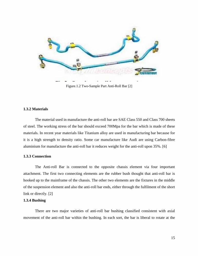
nowadays. [2] The two-sample part anti-roll bar geometrics is shown in Fig.1.2
15
Figure.1.2 Two-Sample Part Anti-Roll Bar [2]
1.3.2 Materials
The material used in manufacture the anti-roll bar are SAE Class 550 and Class 700 sheets
of steel. The working stress of the bar should exceed 700Mpa for the bar which is made of these
materials. In recent year materials like Titanium alloy are used in manufacturing bar because for
it is a high strength to density ratio. Some car manufacture like Audi are using Carbon-fibre
aluminium for manufacture the anti-roll bar it reduces weight for the anti-roll upon 35%. [6]
1.3.3 Connection
The Anti-roll Bar is connected to the opposite chassis element via four important
attachment. The first two connecting elements are the rubber bush thought that anti-roll bar is
hooked up to the mainframe of the chassis. The other two elements are the fixtures in the middle
of the suspension element and also the anti-roll bar ends, either through the fulfilment of the short
link or directly. [2]
1.3.4 Bushing
There are two major varieties of anti-roll bar bushing classified consistent with axial
movement of the anti-roll bar within the bushing. In each sort, the bar is liberal to rotate at the

16
interval the bushing, within the first bushing kind, the bar is additionally liberal to move on bushing
axis, whereas the axial movement is prevented within the second kind.
Material for bushing plays an important parameter. The common material like rubber, Nylon or
polyurethane, but even metal bushing is used in some race car [6]. The bushing is shown in Fig.
Figure.1.3 Bushing (rubber bushings and metal mounting blocks) [6]
1.3.5 Fixtures used to Suspension Members
The connections used between suspension member and the anti-roll is the pin joint is shown
in Fig. 1.4. The connection used to provide is the spherical joint is used as the connection. The
good issue concerning anti-roll bars is that they're terribly turnable by ever-changing bar diameters,
commixture and matching bushing materials or adjusting the instant arm length [6].
Figure.1.4 Pin Joint [6]
17
1.4 Detachable stabilizers
Modern SUVs of the fixed detachable active anti-roll bar. In the middle of the anti-roll bar,
there is a cam sleeve whose connection and disconnection are controlled automatically -
electrically hydraulically. When driving on good roads and high speed says at an average speed of
70km/h, the electronic control unit connects the sleeve. Then the anti-roll bar does not veer
bodywork. When driving on rough roads or fields that the wheels can copy the road surface, the
cam clutch disconnects the right side of the left anti-roll bar.
Stabilizer coupling is activated and quickly drifting bodywork. Body movement transverse
acceleration sequence of sensors, such as a car VW Touareg "running at a speed exceeding 35 km
/ h, the clutch to be engaged at the anti-roll bar in excess the lateral acceleration. This prevents the
vehicle from overturning.
The purpose is to investigate the dependence of the active stability anti-roll bar on rotation
and vertical displacement.
Tasks:
1. To perform the literature review
2. Compare the stiffness of the various dimensions of the anti-roll bar, which will be made of
spring steel
3. Perform an anti-roll bar analysis ANSYS Workbench and ANSYS parametric design language
program
4. Assess how the displacement depends on the size of the forces and the dimensions of the anti-
roll bar
5. Check the stresses and vertical displacements of the designed composite anti-roll bar

18
Chapter-2
Literature Review
The study was done by Mr Pravin Bharane, Mr Kshitijit Tanpure, Mr Ganesh Kerkal
“Optimization of Anti-Roll bar using Ansys Parametric Design Language (APDL) [2] say that the
main goal use for the anti-roll bar is to reduce the body roll. The objective of the researcher
analyses the main geometric parameter which involves affecting the rolling stiffness. All the
analyses are carried out using Ansys Parametric Design language. The Judgement of this paper is
that by locating the bushing near to the bar centre can in increase the stress, the rolling stiffness of
bar is decreased. Anti-roll bar stiffness increases by increasing the bushing stiffness, it also
increases the stress induced in the bar.
The research study was done by Amol Bhanage and Padmanabhan “Static and fatigue
Simulation of Automotive Anti-Roll Bar Before DBTT [4], show that the fatigue life of the anti-
roll bar is compared with four materials. The fatigue life in setting up by using ANSYS Software,
Fatigue model were calculated using ANSYS n code Design life software. shows higher fatigue
life for SAE 5160 with a comparison to AISI 1020, SAE 4340 and SAE 9262. By using the same
load condition above ductile to brittle transition temperature is found out.
The Conclusion is that the fatigue life of SAE 5160 is high compared with AISI 1020. The AISI
1020 is best to use in Anti-Roll Bar
The research study was done by J. Marzbanrad, A. Yadollah “Fatigue life of a passenger
car [9], says that as the principal organizer, a few adjustments are proposed to some current
weariness disappointment models. Numerous clues that might be considered to create general
weakness disappointment models for three-dimensional pressure fields with arbitrary,
nonproportional loadings are specified. At that point, exhaustion life of an against move bar
segment of a traveller vehicle is explored by the numerical strategy lastly, the examination is made
among the aftereffects of the FEM investigation, consequences of the current speculations,
aftereffects of the altered adaptations of the hypotheses, and additionally the trial comes about.
The introduced comes about affirm the exactness of numerical weakness investigation.
The research study was done by Kemal caliskan,” Automated Design Analysis of Anti-
Roll Bar” [6], say that Expanding the cross-sectional width of a hostile to move bar will build its
move solidness. Be that as it may, bigger burdens happen on the bar for a similar bar end diversion.
19
The size factor utilized for perseverance constrain adjustment is additionally influenced by the
distance across of the bar. Finding the bushings nearer to the focal point of the bar expands the
worries at the bushing areas while move firmness of the bar diminishes. Required move solidness
can be acquired with a lower weighting bar by changing the bar material
The research study was done by Bankar Harshal, Kharade Rushikesh, P. Baskar “Finite
Element Analysis of Anti-Roll Bar to Optimize the Stiffness of the Anti-Roll Bar” [17] say that
the main geometric of the body with affecting the stiffness of anti-roll bar is first analysed. Further,
these parameters are additionally influencing the body move edge. By the enhancement of these
geometric parameters, we can ready to build the solidness of bar and which will decrease the body
move point. To compute the solidness of hostile to move bar Finite Element programming ANSYS
is utilized.
The Conclusion, we have got the satisfactory result of anti-roll bar in terms of reducing the roll of
the body that rolls angle of the vehicle by using the simple geometry of anti-roll bar. we can reduce
body roll up to 67.68 % than the vehicle without anti-roll bar so finally, we can conclude that if
the implementation of our modified bar is used then finally stability of the vehicle will be
improved.
The research was done by Hubert, K. and Kumar, A., "Anti-Roll Stability Suspension
Technology," [8] Studied and explained anti-roll bars are usually manufactured from SAE Class
550 and Class 700 Sheets of steel. The steels included in this class have SAE codes from G5160
to G6150 and G1065 to G1090, respectively. Operating stresses should exceed 700 MPa for the
bars produced from these materials.
The research was done by Mohammad Durali and Ali Reza Kassaiezadeh “Design and
Software Base Modeling of Anti- Roll System” [10] say that, examined and proposed the primary
objective of utilizing hostile to move bar is to lessen the body roll. Body roll happens when a
vehicle goes amiss during straight-line movement. The line interfacing the move focuses on the
front and back suspensions shape the move pivot move hub of a vehicle. The focus of gravity of a
vehicle is regularly over this move pivot. In this way, while cornering the radiating power makes
a moving minute about the move hub, which is equivalent to the result of divergent power with
the separation between the move hub and the focal point of gravity.
The study done by Birudala Raga Harshits Reddy “A Review on Anti-Roll Bar used in
Locomotives and Vehicles” [5] has studied about all research paper done by the different
20
researcher on Anti-roll bar. By reading the different paper the researcher gave the details review
about the anti-roll bar like Material, Manufacturing, Function and Development. The reviewer
concluded that the anti-roll bar has a direct effect on car performances, then the reviewer says that
by changing the parameter of the bar, the properties can have improved.
The research done by P.M.Bora, Dr.P.K.sharma “Vehicle Anti-Roll Bar Analyzed Using
FEA tool Ansys” [7] in this researcher changes different parameter and varying the applied load
and find out the deflection, stress and rolling stiffness. He says that when the load on the bar is
gradually increased, the deflection, stress and strain increases corresponding to the bar. He also
concludes that by increasing the cross-sectional diameter it leads to increase in rolling stiffness
and also decreases in deflection and stress. He also says that hollow bar weight ratio is less
compared to a solid bar. When the thickness of hollow bar increases, stress, strain and deflection
decreases, while the weight of the bar increases.
The research was done by Mr.Khartode Ankush.N, Prof. Gaikwad Mahendrals. U “Design
and Analysis of Antiroll Bars for Automotive Application” [8] say that by an increase in efficiency
of a parameter of anti-roll bar reduces the stress at the end of the bar. Increase in diameter of the
bar, which lead an increase of the stiffness and shear stress. The target weight of the bar is reducing
in greater than 60% to 70% of the weight of solid anti-roll bar
The research was done by M.Mohammad Taha, S.M. Sapuan, M.R. Mansor and N. Abdul
Aziz “Development of an Automotive Anti-Roll Bar: A Review” [11] In this the researcher has
done with all the review of the previous research paper about the anti-roll bar. The opinion of the
researcher is that to develop the automotive anti-roll bar should be in the material reinforced
composite material as it has a great potential in the automotive industry. The researcher also
recommended the research should be done with a composite material in order tackle the challenges
and shortcoming in the developing the composite materials.
The research was done by P.Senapathi, S.Shamasundar, G. Venugopala Rao and
B.M.Sachin “Endurance testing and FE analysis of four wheeler automobile stabilizer bar”[13]
The toughness of vehicle stabilizer bar is classed inside the present investigate. Limited detail
examination of the stabilizer bar is done based absolutely at the test perceptions. Weariness
assessment is finished under cyclic stacking. effect of shot peening has been considered.
Exhaustion cycles are portrayed for the maximum loading circumstances. custom constructed
exhaustion testing gear is utilized to re-enact the weariness ways of life of stabilizer bar. business

21
programming program ABAQUS is utilized for numerical recreation. Computational exhaustion
reproduction programming, fe-secure is utilized for the weariness examination to foresee the
weakness presence (an assortment of cycles for break start) and split-site area. Mimicked impacts
have been as contrasted and that of the physical check results for approval.
The research was done by M. T. Mastura, S. M. Sapuan, M. R. Mansor, A. A. Nuraini
“Conceptual design of a natural fibre-reinforced composite automotive anti-roll bar using a hybrid
approach” [14] In this paper the researcher has done the anti-roll bar with the conceptual design
approach and it all use the material of nature fibre-reinforced composite. A new conceptual anti-
roll bar is created with the material nature fibre-reinforced it was created to restrictions from nature
fibre properties. The anti-roll bar needs various design value that also including strength stiffness
and weight the performance was found to the most important as it gained a score of 63.7%. The
anti-roll bar is compared with three different type based on VOC and VOE it should that the natural
fibre-based composite or biocomposite can be used as the material for manufacturing anti-roll bar.
The research was done by H. Bayrakceken, S. Tasgetiren, K. Aslantas “Fracture of an
automobile anti-roll bar” [15] In this study, fracture analysis of an anti-roll bar of the car is carried
out. The analysed type of the anti-roll bar is especially important as many cases are reported about
the fracture after a 100,000 km of travel. Mechanical characteristics of the material are obtained
first. Then, the microstructure and chemical compositions are determined. Some fractographic
studies are carried out to assess the fatigue and fracture conditions. A stress analysis is also carried
out by the finite element technique for the determination of highly stressed regions on the bar.
The research done by Noraishikin Zulkarnain, Fitrian Imaduddin, Hairi Zamzuri, Saiful
Amri Mazlan “Application of an Active Anti-roll Bar System for Enhancing Vehicle Ride and
Handling” [16] This paper analyses the execution of various kinds of the suspension which is the
framework without anti-roll bar, with inactive anti-roll bar and with a dynamic anti-roll bar. A four
DOF vehicle show has been utilized to show the vehicle suspension framework. The
MATLAB/SIMULINK condition of the re-enactment show on the Anti-move plans for four DOF
vehicle dynamic models is utilized to mimic the proposed control arrangement of a dynamic anti-
roll bar and its partners. As per the re-enactment comes about, the execution of the proposed
framework is proficient to accomplish preferable execution over its partners as far as for move
point furthermore, move rate decrease amid roll incited move.

22
Chapter-3
Theoretical Background
Anti-roll bar, considered as one of the most parts of the automotive because it helps to
prevent the vehicle from rollover which causes great damage to the vehicle. It also saves severe
injuries to both passengers and crew members. It also helps vehicle from manoeuvres. One more
benefit of that, it improves traction by controlling the camber angle change caused by body roll.
The anti-roll bar may not have the exact model to get around chassis components or may be much
simpler depending on the car. There are two available specifics to be examined about the anti-roll
bars within the presented and second, the geometry of the bar is under the shape of else chassis
components. The major purpose of anti-roll bar is to cut back the vehicle roll. Body roll seems
once a vehicle moves away from in the direction of motion. The road connection the roll centres
of wheels suspensions forms the roll axis of a body. Centre of gravity of a vehicle is mostly higher
than this roll axis. Thus, whereas turning the centrifugal force creates a roll moment connecting
roll axis, that is adequate to the develop a force with the space between the roll axis and therefore
the CG. Anti-roll bars serve 2 or additional key functions. First, they cut back the role of the body,
as explained higher than, and the second offer some way to once more spreading cornering
hundreds between each wheel, that in turns, given the aptitude of modifying handling
characteristics of the vehicle.
3.1 Determination and Function
The anti-roll bar is subjected force on each side of the vehicle to lower or rise to a certain
height to a minimum the sideways roll of the vehicle during sharp turning or large bounce. Vehicle
wheel can be tilted to large distance when the bar is removed, they are varied in design. There is
familiar use is to force the shock absorber suspension rod to lower or rise to the equal level as the
other wheel. In a fast roll, a vehicle tends to drop nearer to the outer wheels, and therefore the sway
bar before long forces the other wheels to typically meet up with to the vehicle. As an effect, the
vehicle head to "lock" the road nearer in a fast turn, at the point all wheels are closer to the chassis
(body). As soon as the fast turn, then the sliding pressure is cut down, and the dual wheels can
rebind to their regular height against the vehicle, kept at similar levels by the connecting sway bar
[1]. Fig.3.1 shows the SUV image.
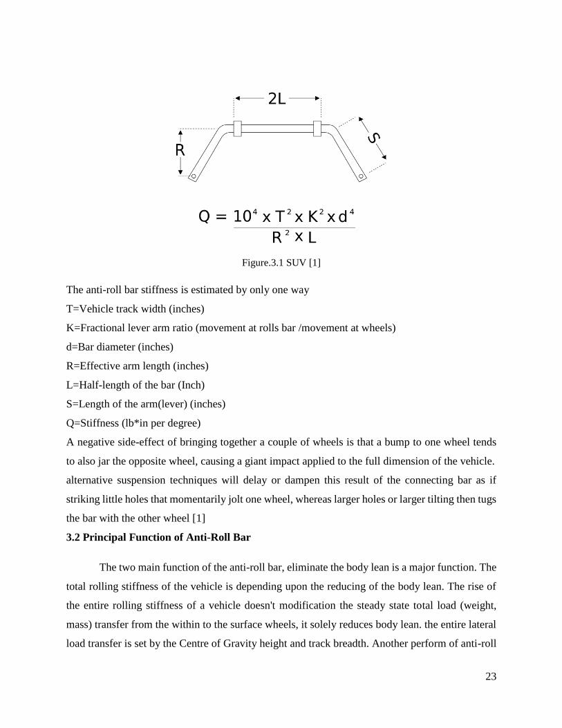
23
Figure.3.1 SUV [1]
The anti-roll bar stiffness is estimated by only one way
T=Vehicle track width (inches)
K=Fractional lever arm ratio (movement at rolls bar /movement at wheels)
d=Bar diameter (inches)
R=Effective arm length (inches)
L=Half-length of the bar (Inch)
S=Length of the arm(lever) (inches)
Q=Stiffness (lb*in per degree)
A negative side-effect of bringing together a couple of wheels is that a bump to one wheel tends
to also jar the opposite wheel, causing a giant impact applied to the full dimension of the vehicle.
alternative suspension techniques will delay or dampen this result of the connecting bar as if
striking little holes that momentarily jolt one wheel, whereas larger holes or larger tilting then tugs
the bar with the other wheel [1]
3.2 Principal Function of Anti-Roll Bar
The two main function of the anti-roll bar, eliminate the body lean is a major function. The
total rolling stiffness of the vehicle is depending upon the reducing of the body lean. The rise of
the entire rolling stiffness of a vehicle doesn't modification the steady state total load (weight,
mass) transfer from the within to the surface wheels, it solely reduces body lean. the entire lateral
load transfer is set by the Centre of Gravity height and track breadth. Another perform of anti-roll
24
bars is to tune the driving balance of an automotive. Steering behaviour may be tuned out by ever-
changing the proportion of the entire rolling stiffness that comes from the front and rear axles.
Increasing the proportion of roll stiffness at the front will increase the proportion of the entire load
(weight) transfer that the front shaft reacts to and reduces the proportion that the rear shaft reacts
to. In general, this makes the outer front wheel run at a relatively higher slip angle, and also the
outer rear wheel to run at a relatively low slip angle, that is an associate under-steer result.
Increasing the proportion of roll stiffness at the rear shaft has the alternative result and reduces
understeer. The perform of stabilizer bars in motorcars is to scale back the body roll throughout
cornering. The body roll is influenced by the occurring wheel load (weight) shift and also the
modification of camber angle.
3.3 Problem Statement
One of the most unrecognised part but yet important component hiding under the vehicles
is the anti-roll bar bushings. Located on the chassis of the vehicle and used to reduce road noise,
absorb bumps and cracks in the road and deliver a softer ride, the anti-roll bar is fixed with rubber
bushings that keep the vehicle’s body from rolling as it manoeuvres turns.
When it is properly lubricated and maintained, the anti-roll bar bushings can bring excellent
driving conditions for many years. At the point when the bar begins to weakness, the alert signs
can go from subtle noises to significant problems with steering and handle this potentially leading
to a vehicle accident and other safety concerns.
3.3.1Inactive in vehicle handling
Since when driving the car routinely. It’s likely that we can have an unmistakable
comprehension of how the car handles the road. Simple way to identify problem with the anti-roll
bar bushings are the point at which when the handling seems inactive or respond slowly, mainly
when the vehicle makes a sudden turn and during take turn near the corner, the vehicle appears to
be less steady than it has been beforehand, this is likewise a caution of bushings has been worn out
and need to be restore to new bushings.
3.3.2 Rattling under the chassis of the car
The anti-roll bar is found specifically under the car. At the point when bushings are worn
out, exhausted or totally breakout, the anti-roll bar itself will end up flexible and cause a rattling
25
or thumping sound while we are driving. The turbulence will get continuously louder when you
steer the car in either direction or when you are driving on the hard road. Mostly the noise will
come from the front end of the vehicle, near the feet on the floor area and are very easily notable.
3.3.3Squeaking Sound from under the vehicle
Not quite the same as a shake or thumping sound, the squeaking commotion originating
from under the car is a potential cautioning sign that the bushings are beginning to wear. This
sound is detectable while you are rolling over knocks, making forceful swings to one side or right,
or an event that you crash into the garage. This noise is normally caused by an anti-roll bar bushing
that isn’t appropriately greased up because of metal-on-metal contact.
3.4 Type of Suspension System
Vehicle suspension - is a system that needs to maintain the body at a certain height above
a road and transmit forces generated by driving over bumps or when braking when cornering. No
less important is the ride comfort, which is ensured by vibration and shock damping. The
suspension comprises rigid and flexible elements connecting the vehicle wheels with the
bodywork. Constructor to align the many, often conflicting functions were developed different
solutions
3.4.1 McPherson's Suspension
McPherson strut suspension is used in the methodology of depreciation on vehicles with
front-wheel drive. This decision deserves special attention because in many cases, the front
suspension is used McPherson suspension. The lower-class cars, it is almost the only applicable
solution. McPherson suspension column significantly simplified, as cushioning, supporting and
steering functions of the elements have been merged into a single system. In addition, it takes up
little space, which is particularly important in front wheel drive case at the transverse drive system
layout. The main elements of the column are a shock absorber and helical spring. The upper shock
absorber fastening element bearing column gives the possibility to rotate around its axis turn the
wheels. The column is rigidly connected to the swing bracket (bracket) and swing arm ball joints
(joints) is connected to the lever.

26
3.4.2 The double hinge suspensions
New production cars are often having a double hinge with Chassis. This decision every
single axle wheel moves and the amortization independently of the other wheel. Used in the end,
and sometimes the front of the vehicle suspension and ensure a high level of ride comfort.
At the same time preserves the excellent driving characteristics. Each design has its own decision,
but the general principle is the same. The double Structures based on the longitudinal, transverse
and diagonal levers and a rod connected to the system to ensure the driving comfort. A common
solution is lower longitudinal arm system with two transverse rods (top, which is attached with a
spring shock absorber and bottom). This prevents the rear suspension wheel angle changes with
increasing vehicle load
3.4.3 Dependent suspension
Transverse suspension guides, that is four fixing points of two arms of aluminium, creates
a support side and longitudinal forces. All four levers are connected to the wheel supports ball-
joints. The upper parts are arms attached to the bracket and the bottom - to the section rails.
Validating rubber and metal sleeves.
According to the relationship between the wheels, the suspension can be dependent and
independent. Addict sits on both wheels are mounted to a continuous axle beam. Then, one of the
slipping wheels vertical direction, and other necessary moves. That the majority of commercial
vehicles of all bridges and some of the car’s rear axle suspension.
3.4.4 Independent suspension
When times are an independent suspension, a drive axle is attached to one bar connected
to the chassis. Drive wheels two levers connected to the crossbar Levers to respectively jet and
braking moments bodywork. Steered axles time the front of the car, gives the shoe resulting from
the longitudinal and lateral forces. They drive a car. Steered bridges are continuous and composite.
3.5 Anti-roll bar Position
The anti-roll is usually found in car suspensions system. The type anti-roll bar is shown in
Fig. The anti-roll bar is usually made upon spring steel. The anti-roll bar is made of a solid, round,
spring steel pole with a breadth of 10-60mm or an empty tube. The stabilizer can likewise be made
of composites on the grounds that the composite materials are light and strong and are reasonable

27
for use in the making of a stabilizer. Because of the properties of composite materials, a stabilizer
made of composites is light and strong [20]
Figure.3.2 various type anti-roll bar connection [20]
Stabilizers typically connect one side of the same axle with the other side wheel. They are
connected by a metallic rod, and at its end, depending on the type, is fixed connections, hinges.
Stabilizers typically connect one side of the same axle with the other side wheel. They are
connected by a metal rod, and at the rear, depending on the structure, the connections, hinges. It is
secured to the lower forks or shock absorber according to the vehicle brand or model of the
structure
The middle part of the stabilizer is fastened transversely to the body rubber bushings (1).
The stabilizer elbows 3 are attached to the wheel suspension on the left and right axles. There are
also cars with 2 stabilizers. The Fig.3. The stabilizer can be both front and rear, but usually only
in front of the car. Some cars do not have a stabilizer because they were not intended for their
construction.

28
Figure.3.3 Anti-roll Bar [16]
3.6 The effect of the anti-roll bar on comfort
The three important aspects that check the safety of the cars when driving at high speed or
in turn of the vehicle are driving comfort, driving and maintaining vehicle stability. To ensure
driving comfort, the chassis of the car must abolish the vibrations caused due to unevenness’s road.
The vehicle must be smoothly controlled by the rotating manoeuvres. The tire contact with the
road surface must be good in order to maintain the vehicle stability and braking capabilities.
In the car, the anti-roll bar is a very essential element for a vehicle with independent suspension
system, which helps to improve vehicle stability. The performance of the anti-roll bar is directly
proportional to safety, because if there is no anti-roll bar, then there would be a high turning point
during the corner of the vehicle. According to statistics, the chance of the rollover is reduced about
60% to 80% when the vehicle is installed with an anti-roll bar.
The anti-roll bar also less the vibration angle in the small car. The anti-roll bar usually places in
the front end of the vehicle. This is of steel rod. The bar middle part is fixed to the body by means
of rubber bushings. The folded ends are connected to the brackets of the lower link arms. Hanging
over the body of the car, on one side the spring deforms more, and the body approaches the wheel.
Turning the stabilizer bar makes the wheel on the other side approach the body. This prevents the
body from turning to the sides.
3.7 Audi R8 Anti-roll Bar
The dynamic stability anti-roll bar is made by carbon fibre, which comprises a carbon fibre
tube and an aluminium elbow. This design is lighter than 35% of the standard steel squeezed steel
anti-roll bar. [19] This shown in Fig.3.4

29
Figure.3.4 Anti-roll bar Audi R8 [19]
30
Chapter 4
Methodology
The stress field at the bar will be investigation utilizing a three-dimensional finite element solid
model. There are two different vital certainties to be considered about the anti-roll bar that in the
first place, the counter moving firmness of the bar has the immediate impact on the turning
attributes of a car. What is more, second the geometry of anti-roll bar is reliant on the geometry
of the different body segments. The main objective of the master’s thesis
• To check the anti-roll bar are designed according to the spring design manual.
• To ensure the bar is designed to withstand the rolling stiffness and the deflection at end of
the bar.
• To execute that the stress of the bar is less than the desired stress.
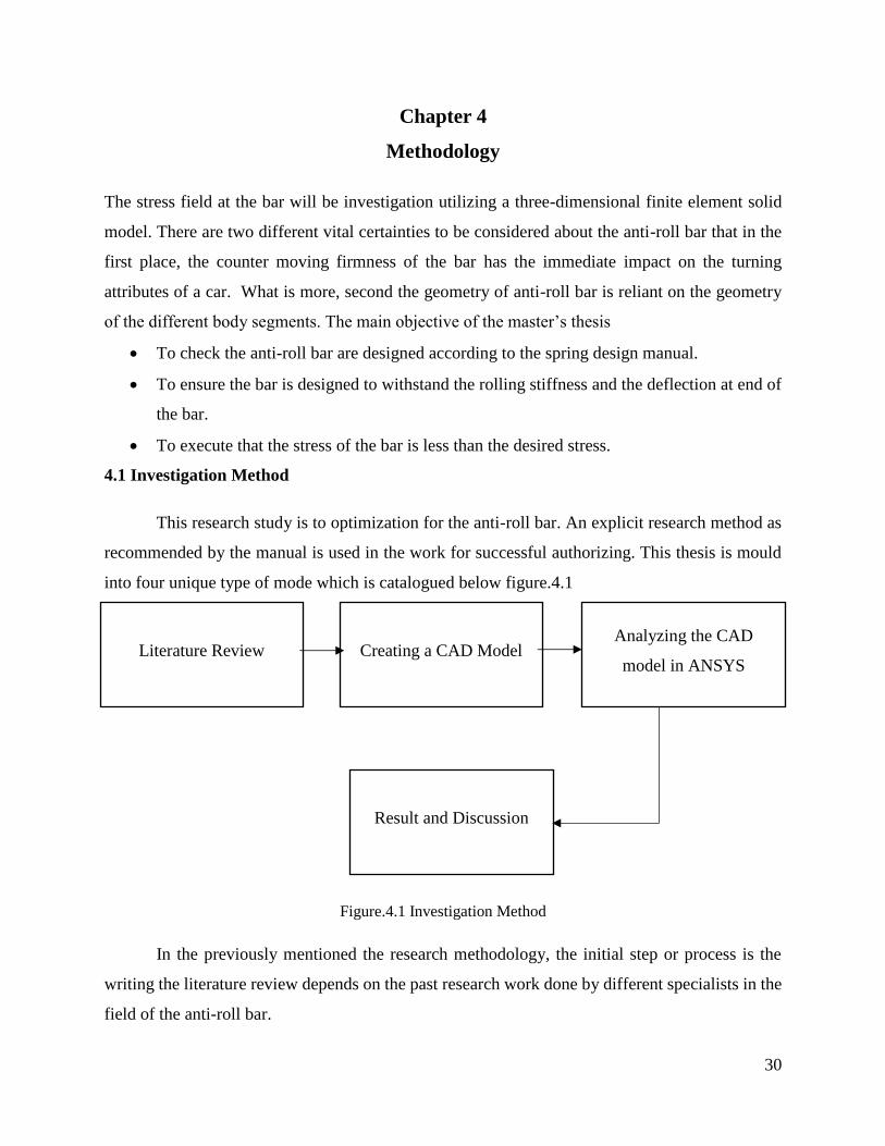
4.1 Investigation Method
This research study is to optimization for the anti-roll bar. An explicit research method as
recommended by the manual is used in the work for successful authorizing. This thesis is mould
into four unique type of mode which is catalogued below figure.4.1
Figure.4.1 Investigation Method
In the previously mentioned the research methodology, the initial step or process is the
writing the literature review depends on the past research work done by different specialists in the
field of the anti-roll bar.
Literature Review
Result and Discussion
Analyzing the CAD
model in ANSYS Creating a CAD Model
31
The next procedure is picking a substantial model for the research to convey forward. An
appropriate model is an outline utilizing CAD software. In this work, SOLIDWORKS is utilized
as a CAD programming for the planning of a model. The four procedure is the imperative process
in which the designed model is analysed with the help of the analysis software. The last advance
is the discourses area in which the outcomes are talked about and some reasonable remedy controls
are examined.
4.2 Materials
For the anti-roll bar analysis materials selected is structural steel
4.2.1 Introduction to structural steel
The structural steel is a low hardenability and low malleable carbon steel with Brinell
hardness of 119-234 and elasticity of 410-790Mpa. It has high quality, high malleability and great
weldability. It is typically utilized as part of turned and cleaned or icy drawn condition. Because
of it is low carbon content, it is impervious to enlistment solidifying or fire solidifying. Because
of the absence of an alloying component, it won’t react to nitriding. In any case, carburization is
conceivable keeping in mind the end goal to get case hardness more than RC65 for littler segments
that decrease with an expansion in area measure. Centre quality will stay as it has been provided
for every one of the segments. Then again, carbon nitriding can be performed, offering certain
advantages over standard carburizing.
Steel can be great extent used in every modern division with a specific end goal to upgrade
weldability or machinability properties. It is utilized as a part an assortment of utilization because
it is cool drew or turned and cleaned complete property. The mechanical properties of Steel is
shown in the table 4.1.
Table.4.1 Physical Properties
Property Values
Density 7850 kgm−3
Tensile Yield Strength 2.5E+08
Compressive Yield Strength 2.5E+08
Tensile Ultimate Strength 4.6E+08
Poisson Ratio 0.3
32
4.3 CAE Tools
CAE tool is broadly utilized as apart of vehicle industry. Accordingly, the car manufacturer
has lessened item advancement cost and time while enhancing security, solace, and sturdiness of
the vehicle they deliver. The prescient capacity of CAE apparatuses has advanced to the point
where a great part of the plan confirmation is presently done utilizing computer re-enactments as
opposed to physical model testing. Tools utilize as a part of this investigation are quickly clarified
beneath
4.3.1 System Analysis
The computer and data innovation are a necessary piece of the advanced enlightened world.
The computer has turned into a vital apparatus and architect. Be that as it may, until further notice,
he cannot supplant what is called designing reasoning. Looked with another issue, the designer
must finish the assignment, utilizing the notable standards of material science, arithmetic and
different sciences. The computer can just complete human-customized directions. He does this
rapidly and precisely. The human concern is to furnish the computer with revised information. A
computer can perform estimations productively, however, it cannot autonomously, without human
mediation, details an undertaking, assemble a count plot, check presumptions, select the fitting
strategies for choosing and condition, check whether the outcome is sensible, reach determinations
and make suggestions. Up until this point, there is just a single step in building investigation
methodology, which is in a perfect world suited for the computer for the calculation.
As has just been said, different computer programming can be utilized for computer analysis.
Notwithstanding, such fundamental project is utilized that depend on finite element method. The
market offers various bundles of this compose, so the inquiry is which one to look over. On the
planet, a standout amongst the most famous and most adaptable computer project of this write is
Ansys. Understanding crafted by this program can without much of a stretch be connected to an
arrangement of analysis tasks.
4.3.2Ansys Simulation
For finite element analysis, ANSYS Workbench programming is utilized. ANSYS is a
computer-aided engineering software which is utilized to decide finite element, structural analysis,
Computational Fluid Dynamics analysis, Explicit and Implicit method. For our case, static
33
structural is done to decide the disfigurement of the structure and different parameters, for
example, the pressure and vitality consumed by the structures. These figurines are then checked
with the hypothetical computations to decide the quality of the superstructures. Infinite element
investigation, the entire anti-roll is discretized into smaller element called as finite element and the
analysis is done. The precision of the components relies upon the meshing. Ansys software is used
as simulation program.
4.4 Model Description
The standard model of the anti-roll is chosen the model is drawn as per the spring design
manual. The danti-roll bar with a hollow circular section for geometrical has been considered
important parameter that is used to draw the model in SOLIDWORKS software is listed in the
below table
Table.4.2 parameter of the Anti-roll bar
Specification Values
Type of cross-section Hollow circular cross-section
Full length of the bar 1100mm
Location of bushing ±400
Internal diameter 22
External diameter 18
4.5 SOLIDWORKS Model
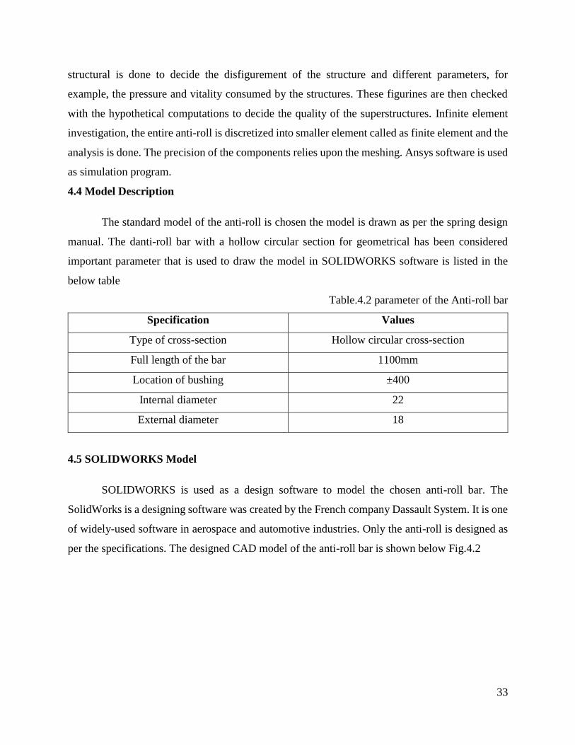
SOLIDWORKS is used as a design software to model the chosen anti-roll bar. The
SolidWorks is a designing software was created by the French company Dassault System. It is one
of widely-used software in aerospace and automotive industries. Only the anti-roll is designed as
per the specifications. The designed CAD model of the anti-roll bar is shown below Fig.4.2
34
Figure. 4.2 Anti-roll Bar in CAD Model
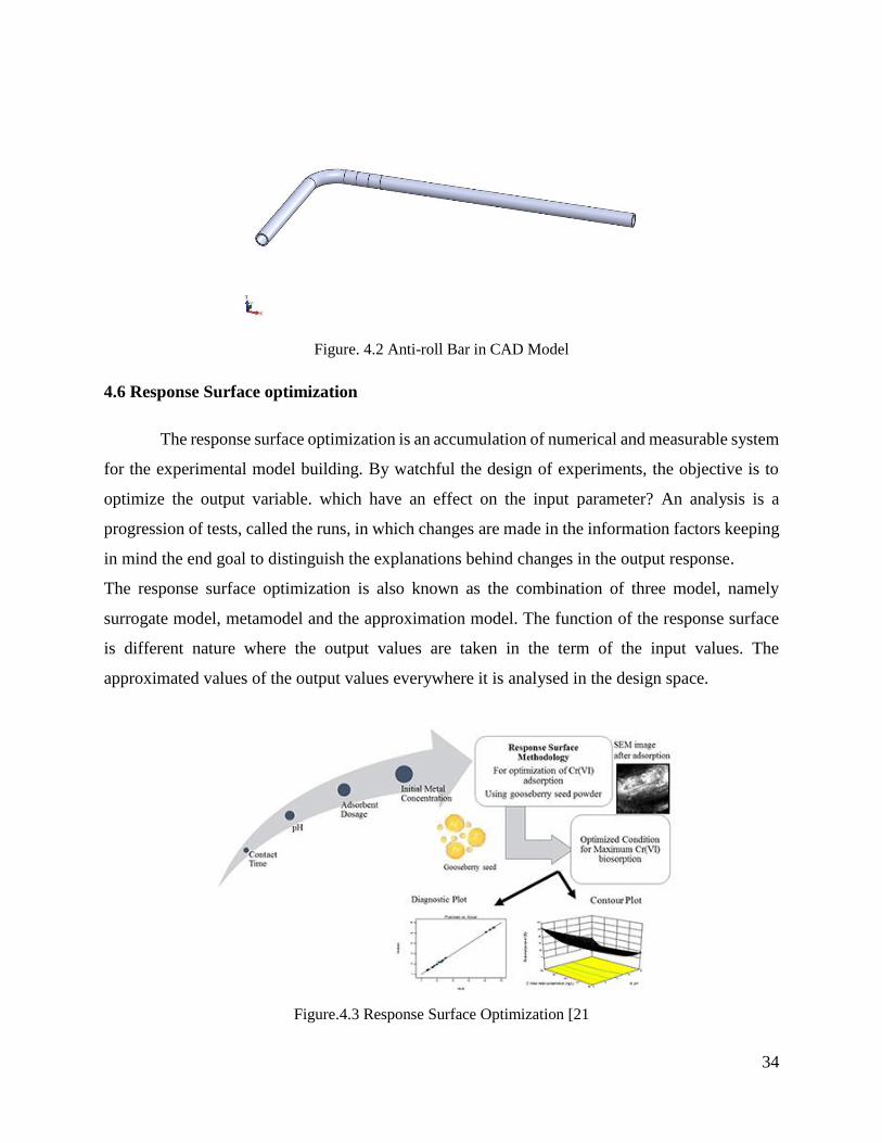
4.6 Response Surface optimization
The response surface optimization is an accumulation of numerical and measurable system
for the experimental model building. By watchful the design of experiments, the objective is to
optimize the output variable. which have an effect on the input parameter? An analysis is a
progression of tests, called the runs, in which changes are made in the information factors keeping
in mind the end goal to distinguish the explanations behind changes in the output response.
The response surface optimization is also known as the combination of three model, namely
surrogate model, metamodel and the approximation model. The function of the response surface
is different nature where the output values are taken in the term of the input values. The
approximated values of the output values everywhere it is analysed in the design space.
Figure.4.3 Response Surface Optimization [21

35
Chapter 5
Calculation of Anti-roll bar
The outline of the anti-roll bar and the unbending nature of the material must be picked so as too
hard to coordinate the mechanical properties and guarantee an adequate level of solidness and driving
steadiness while driving. Since it is difficult to examine the properties of a dynamic anti-roll bar, keeping
in mind the end goal to choose the right one, it is important to make certain computations that are hard to
discover in the logical writing.
Anti-roll bar utilized as a part of the creation of organization are produced by their own particular
breaks down and are not freely accessible. Dissimilar to the attributes of the sleeves or the pressure
of the anti-roll materials, which can be found in the writing. Every so often, the state of the anti-
roll bar is likewise reported
The Society of Automotive of Engineering presents general information on the Anti-roll
bar, its generation and determination in the book (spring Design Manual) see Appendixes 1. The
dynamic strength anti-roll bar is appointed to the spring gathering. There are a few recipes in the
manual that can utilize to ascertain the solidness of the anti-roll bar, the diversions at the anchorage
point under certain heap powers. Be that as it may, these equations must be connected to standard
frame anti-roll bar. The accompanying demonstrates frame anti-roll bar (shown in Fig.5.1), which
will be utilized for logical estimations
Figure.5.1 Anti-roll bar geometric form used from Spring Design Manual [18]
According to the image point A and the stabilizer is subjected to a force. The formulas to
calculate the stiffness of the stabilizer [18].
36
The formula used to find this halfway track Length [L]
L = a + b + c (5.1)
Where,
L = Halfway Track length, mm
𝑓𝐴 =𝑃
3𝐸𝐼[𝑙1
3 + 𝑎3 +𝐿
2(𝑎 + 𝑏)2 + 4𝑙2
2(𝑏 + 𝑐) (5.2)
𝑓𝐴 = Deflection At ‘A’ (mm)
E= Young’s Module’s (GPa)
I = Moment of Inertia (mm), I=𝜋𝑑4
64
The rolling stiffness of the bar is calculated as [18]
𝑘𝑅 =𝑃𝐿2
2𝑓𝐴 (5.3)
Where,
𝑘𝑅 = Rolling stiffness (Nmm/rad)
P = Load Applied on the Anti-roll Bar (N)
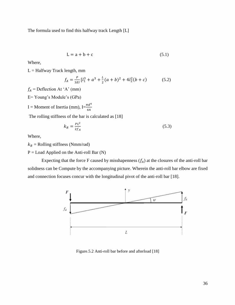
Expecting that the force F caused by misshapenness (𝑓𝐴) at the closures of the anti-roll bar
solidness can be Compute by the accompanying picture. Wherein the anti-roll bar elbow are fixed
and connection focuses concur with the longitudinal pivot of the anti-roll bar [18].
Figure.5.2 Anti-roll bar before and afterload [18]
37
On the off chance that the suspensions are of a free sort, at the point, the wheel relocation
concurs with the stabilizer move. In like manner, we can compute the angle 𝜑
The Rolling stiffness of the bar is calculated by three different methods
𝑘𝑅 =𝑃𝐿2
𝑓𝐴
Nmmm⁄ (5.4)
𝑘𝑅 =𝑃
𝑓𝐴
Nmm⁄ (5.5)
𝑘𝑅 =𝑃𝐿
tan−1 𝑓𝐴𝐿2
Nmdeg⁄ (5.6)
Where,
P= Load applied on the bar N
L = halfway track length mm
5.1 Diameter calculations
The design of the anti-roll bar is very important to choose the correct diameter. The anti-
roll bar can be neither too small in diameter than the larger diameter, and the diameter is counted.
According to the preceding chapters the calculating the anti-roll bar stiffness (𝑘𝑅) and rotating
bending determine the appropriate beam diameter according to the formula
d =
√[1283 ∗ 𝜋 ∗
𝑘𝑅
𝐿2 ∗ 𝐸]
4
[𝑙13 + 𝑎3 +
𝐿2 (𝑎 + 𝑏)2 + 4𝑙2
2(𝑏 + 𝑐)
5.2 Analytical method
fA =P
3EI[l1
3 + a3 +L
2(a + b)2 + 4l2
2(b + c) mm
fA =1000
200000 ∗ 3 ∗ 63460.01716[2503 + 703 +
550
2(70 + 60)2 + 42302(420 + 60)
fA = 34.509 mm

38
kR =PL
tan−1 fAL2
Nmdeg⁄
kR =1000 ∗ 1100
tan−1 34.5091100
2
Nmdeg⁄
kR = 306.38 Nmdeg⁄
5.3 Numerical Analysis in ANSYS
For our case, another technique for computer simulation is proposed in which ANSYS is
utilized to decide the quality of the anti-roll bar. Statics structural analysis is looked at the changed
kind of analysis. In the Numerical analysis, the ANSYS workbench program was additionally used
to calculate the displacement and stress of the anti-roll bar by finite element method, however
utilizing the integral body. The following figure demonstrates the geometric model of the anti-roll
bar which was simulated by the SOLIDWORKS programming package. The created model of the
anti-roll bar is imported into ANSYS for the analysis reason. Once the model is imported the
engineering data is set for the model. The engineering data include the material data in that the
material used for the model and it is properties are selected. For the anti-roll material selected
from the engineering data is structural steel. The imported model is shown in Fig.5.3. The step
involved in ANSYS Workbench is illustrated in the below Fig.5.3
Figure.5.3 Imported Geometry and ANSYS Workbench analysis steps
5.4 Model setup
After the model is imported in ANSYS. The next step in workbench is to analysis the model
in model setup. In this step, the data regarding static structural analysis is given. The data’s like

39
fixtures, load and other related data to the model are given which are needed for running the static
analysis
5.4.1 Remote Displacement: The anti-roll bar is given with the remote displacement constraint to
fix the end to arrest the motion in the particular direction and rotations. The table.5.1 below is
listed at what the point the component is to fixed and free. The ‘zero’ indicate that component are
arrested for all DOF, the “FREE’ indicated the component is free in all DOF. The below figure.5.4.
showing the remote displacement (shown in the black circular).
Table.5.1 Remote Displacement
Figure.5.4 Remote Displacement
Type Remote Displacement
X component 0 mm
Y component 0 mm
Z component Free
X rotation Free
Y rotation 0
Z rotation 0

40
5.4.2 Connections: For this model connect is used. The spring connect is used, it is connected to
the body-ground connections. The spring is connected to a length (400mm) from the x-axis. The
type of spring is selected is longitudinal, the spring has both behaviour (tension and compression).
The longitudinal stiffness value of the spring is 1500 N/mm. The behaviour of the spring is rigid.
The Figure.5.5 Shown the connections (shown in black Circle).
Figure.5.5 Spring Connections
5.4.3 Load: The load is applied at the end of the bar applied load is in the z-axis coordinates
1000 N is applied to the bar. The below figure.5.6 shows the applied load
Figure.5.6 Load

41
5.5 Meshing
The exactness of the finite element analysis relies on the precision of meshing. A Fine mesh is
chosen and whole structure has meshed. The accompanying table 5.2 is shown the mesh
information in detail:
Table.5.2 Meshing details
Size function Adaptive
Relevance centre Fine
Element size 50.00mm
Number of nodes 5752
Number of element 816
Transition Fast
Minimum edge length 50.2650 mm
The below figure.5.7 showing the Meshing of the bar
Figure.5.7 Meshing
42
Chapter 6
Result and Discussion
After the calculation are done for the bar and the model is imported in the ANSYS
workbench, the investigation is done to find the total deformation of the bar and the results are
obtained. In this section discusses those outcomes and it impacts on the rolling stiffness is also
analysed
6.1 Analysis of Anti-roll in finite element analysis result
The anti-roll bar of the car is analysed in ANSYS with the given load as shown in section 5.4.3.
Two solutions are required for anti-roll bar are obtained from the finite element analysis are shown
below
• Total Deformation
• Equivalent Stress
6.1.1 Total deformation
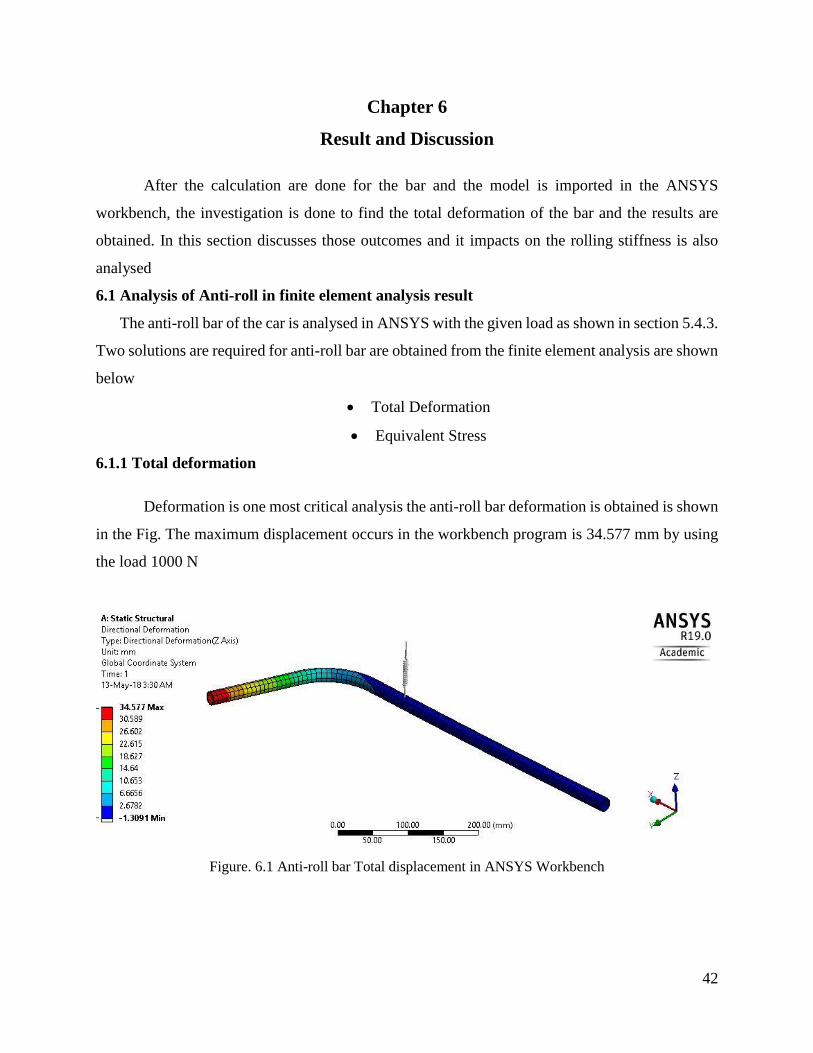
Deformation is one most critical analysis the anti-roll bar deformation is obtained is shown
in the Fig. The maximum displacement occurs in the workbench program is 34.577 mm by using
the load 1000 N
Figure. 6.1 Anti-roll bar Total displacement in ANSYS Workbench
43
6.1.2 Equivalent Stress
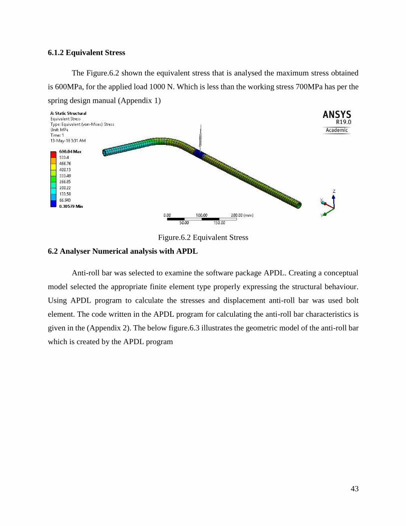
The Figure.6.2 shown the equivalent stress that is analysed the maximum stress obtained
is 600MPa, for the applied load 1000 N. Which is less than the working stress 700MPa has per the
spring design manual (Appendix 1)
Figure.6.2 Equivalent Stress
6.2 Analyser Numerical analysis with APDL
Anti-roll bar was selected to examine the software package APDL. Creating a conceptual
model selected the appropriate finite element type properly expressing the structural behaviour.
Using APDL program to calculate the stresses and displacement anti-roll bar was used bolt
element. The code written in the APDL program for calculating the anti-roll bar characteristics is
given in the (Appendix 2). The below figure.6.3 illustrates the geometric model of the anti-roll bar
which is created by the APDL program

44
Figure.6.3 Geometric of Anti-roll bar in ANSYS APDL
The above figure shows that the anti-roll bar the point A is constrained in some direction. At the
point A, the anti-roll bar cannot move in the z-axis, but it can move smoothly in y-axis and x-axis. In
addition, to that, the point A the anti-roll bar cannot rotate about y-axis and z-axis, but it can smoothly
rotate in the x-axis. The upward force is also applied at the point A.
At the point B, the anti-roll bar can translate in the y-axis, but it cannot move in x-axis and
z-axis. Similar to that the Point B can rotate around the x-axis and z-axis. The downward force is
also applied at the point B
when the modelling the anti-roll bar, it was necessary to take into account the fact that the
anti-roll bar is fastened with bushings. Spring with a rigidity of 1500 N/mm was used to simulate
locally space bushings. Such spring stiffness is closest to the rigidity of rubber bushing.
The results of the equivalent stresses and total displacement obtained by linear analysis are shown
in figure 6.4 and 6.5 respectively
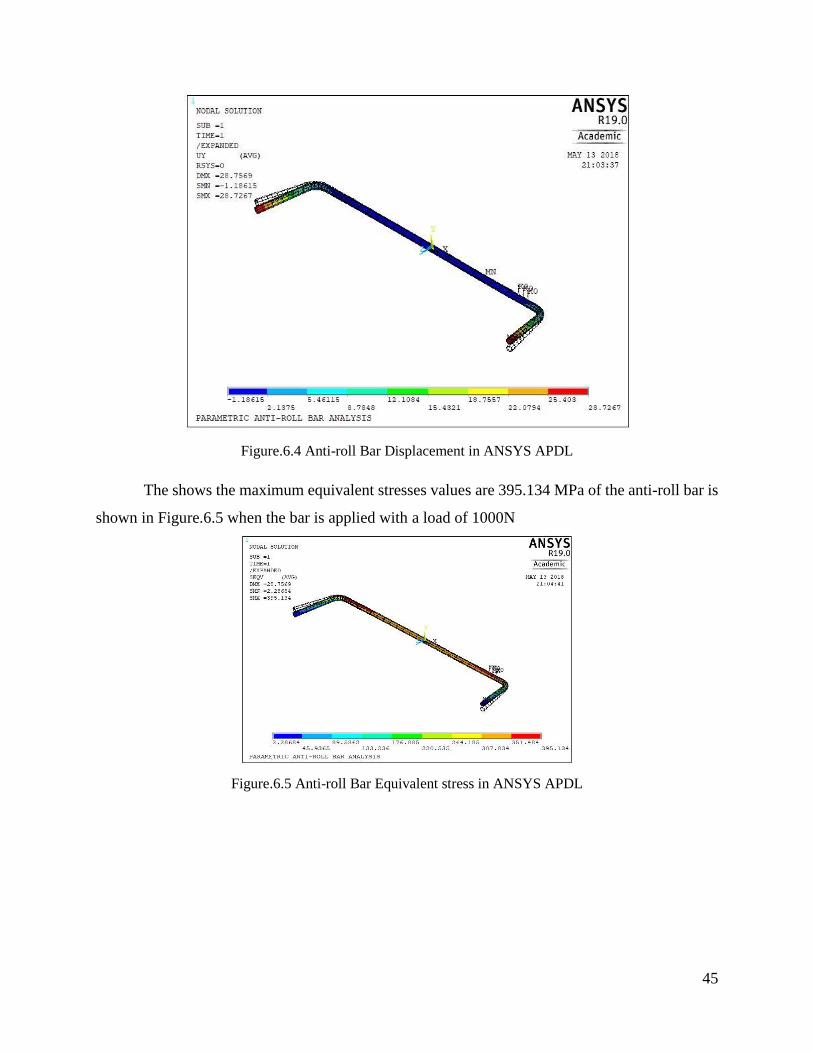
The highest displacement values are 28.7267mm of the anti-roll bar is shown in Figure.6.4,
When the anti-roll bar is applied with 1000 N.
45
Figure.6.4 Anti-roll Bar Displacement in ANSYS APDL
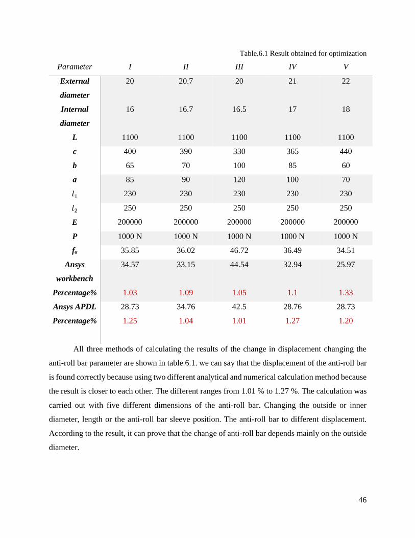
The shows the maximum equivalent stresses values are 395.134 MPa of the anti-roll bar is
shown in Figure.6.5 when the bar is applied with a load of 1000N
Figure.6.5 Anti-roll Bar Equivalent stress in ANSYS APDL
46
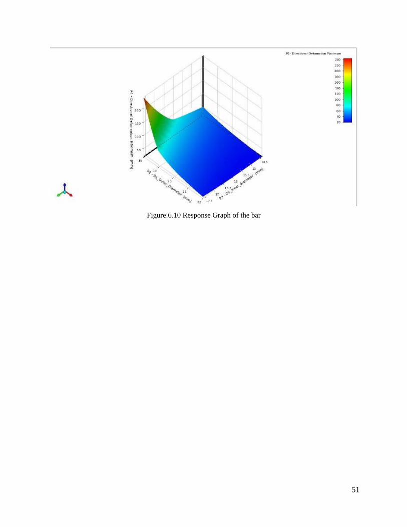
Table.6.1 Result obtained for optimization
Parameter I II III IV V
External
diameter
Internal
diameter
L
20
16
1100
20.7
16.7
1100
20
16.5
1100
21
17
1100
22
18
1100
c
b
400
65
390
70
330
100
365
85
440
60
a
𝑙1
85
230
90
230
120
230
100
230
70
230
𝑙2
E
250
200000
250
200000
250
200000
250
200000
250
200000
P 1000 N 1000 N 1000 N 1000 N 1000 N
fa 35.85 36.02 46.72 36.49 34.51
Ansys
workbench
Percentage%
34.57
1.03
33.15
1.09
44.54
1.05
32.94
1.1
25.97
1.33
Ansys APDL
Percentage%
28.73
1.25
34.76
1.04
42.5
1.01
28.76
1.27
28.73
1.20
All three methods of calculating the results of the change in displacement changing the
anti-roll bar parameter are shown in table 6.1. we can say that the displacement of the anti-roll bar
is found correctly because using two different analytical and numerical calculation method because
the result is closer to each other. The different ranges from 1.01 % to 1.27 %. The calculation was
carried out with five different dimensions of the anti-roll bar. Changing the outside or inner
diameter, length or the anti-roll bar sleeve position. The anti-roll bar to different displacement.
According to the result, it can prove that the change of anti-roll bar depends mainly on the outside
diameter.

47
6.3 Parameter c6orrelations for the Anti-roll bar
During the anti-roll bar calculations, the person correlations were also performed. The rule
for the calculating the person correlation coefficient is extremely straightforward. The computation
of this correlations coefficient is contrasted with the rank of two successions. For this reason,
contrasts between the rankings are discovered, they are put in a square and put together. At that
point, extra coefficients are added to the count so the coefficient esteems change form -1 (which
show very strong negative associates) to +1 to an exceptionally solid positive correlation. In the
event that the coefficient is zero, this shows there are no statistical connections
r = ∑((𝑋 − �̅�)(𝑌 − �̅�))
√∑(𝑋 − �̅�)2 ∑(𝑌 − �̅�)2
where,
X- parameter1 values
Y- parameter2 values
X̅-Mean of parameter1 values
Y̅-Mean of parameter2 values
In the today case, the person correlation is made with the ANSYS Design Xplorer (shown is
Fig.6.6)
Figure.6.6 Design Xplorer with correlation

48
The correlation matrix was carried out after the completion of Analysis, which is shown in Fig.6.7
Figure.6.7 Correlation Matrix Parameter
As stated by the correlation matrix, it is seen that the external diameter of the anti-roll bar
has the highest effect. It is seen from the correlation matrix that the external diameter is indirectly
proportional to the displacement of the anti-roll bar, the greater the external diameter, the smaller
the displacement. Be that as it may, the anti-roll bar mass is specifically corresponding to the
external diameter of the anti-roll bar. For the instance, the bigger the external diameter, the bigger
the anti-roll bar mass will be.
The anti-roll bar stress has a weak opposite correlation with the external diameter of the
anti-roll bar. The anti-roll bar moves additionally depend directly on the internal diameter of the
anti-roll bar, however, it is frail.

49
In the below Fig.6.8 illustrate the sensitivity of the parameter, which epitomises these day
parameter correlation matrix is shown in Fig.6.7. How strongly the displacement, the mass, the
stresses from the anti-roll bar dimensions depend
Figure.6.8 Sensitivity of the parameter
6.4 Response Surface Optimization
Response Surface optimization utilizes a grouping of outlined analyses to acquire an ideal
reaction. The effective approach for the outline of computationally costly models, for example,
those found in aviation frameworks, including optimal design, structures and so on. Offers both
subjective plan appraisal. The response surface method is not in itself a streaming agent, but
instead an instrument for expanding the speed of enhancement. It predicts the reaction of a
framework for a working point without really performing a re-enacted investigation by then.
In the today case, the Response Surface Optimization is made with the ANSYS Design
Xplorer (shown in Figure.6.9)

50
Figure.6.9 Design Xplorer with correlation
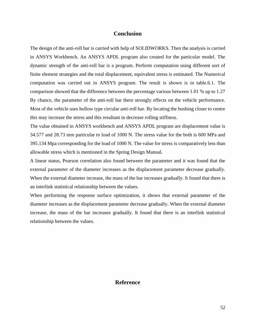
In the below figure.6.10 it shows clearly that when there is an increase in the diameter of
the bar, there is a gradual decrease in the total deformation. There is gradually response in the
graph. This response surface is the powerful tool in the field of optimization.
51
Figure.6.10 Response Graph of the bar
52
Conclusion
The design of the anti-roll bar is carried with help of SOLIDWORKS. Then the analysis is carried
in ANSYS Workbench. An ANSYS APDL program also created for the particular model. The
dynamic strength of the anti-roll bar is a program. Perform computation using different sort of
finite element strategies and the total displacement, equivalent stress is estimated. The Numerical
computation was carried out in ANSYS program. The result is shown is in table.6.1. The
comparison showed that the difference between the percentage various between 1.01 % up to 1.27
By chance, the parameter of the anti-roll bar there strongly effects on the vehicle performance.
Most of the vehicle uses hollow type circular anti-roll bar. By locating the bushing closer to centre
this may increase the stress and this resultant in decrease rolling stiffness.
The value obtained in ANSYS workbench and ANSYS APDL program are displacement value is
34.577 and 28.73 mm particular to load of 1000 N. The stress value for the both is 600 MPa and
395.134 Mpa corresponding for the load of 1000 N. The value for stress is comparatively less than
allowable stress which is mentioned in the Spring Design Manual.
A linear status, Pearson correlation also found between the parameter and it was found that the
external parameter of the diameter increases as the displacement parameter decrease gradually.
When the external diameter increase, the mass of the bar increases gradually. It found that there is
an interlink statistical relationship between the values.
When performing the response surface optimization, it shows that external parameter of the
diameter increases as the displacement parameter decrease gradually. When the external diameter
increase, the mass of the bar increases gradually. It found that there is an interlink statistical
relationship between the values.
Reference

53
Design and Analysis of Antiroll Bars for Automotive Application, Mr Khartode Ank Prof.
Gaikwad. Mahendra. Uush.N, International Journal on Recent and Innovation Trends in
Computing and Communication, Volume:4 Issue:6, 340 – 345
Optimization of Anti-Roll bar using Ansys Parametric Design Language (APDL), Mr Pravin
Bharane, Mr Kshitijit Tanpure, Mr Ganesh Kerkal, International Journal of Engineering Research
and General Science Volume 2, Issue 5, August-September, 2014, 699-706
Product Development Support with Integral Simulation Modeling, Somnay, R.Shih, SAE
Technical Paper Series, paper No: 1999-01-2812, 1999.
Static and Fatigue Simulation of Automotive Anti Roll Bar before DBTT, Amol Bhanage,
Padmanabhan Krishnan, International Journal of Applied Engineering Research · August 2015,
472-476
A Review on Anti-Roll Bar used in Locomotives and Vehicles, Birudala Raga Harshits Reddy,
International Journal of Current Engineering and Technology, Vol.7, No.3 (June 2017), 838-841
Automated Design Analysis of Anti-Roll Bars, Kemal Caliskan, September 2003
Vehicle Anti-Roll Bar Analyzed Using FEA Tool Ansys, P.M.Bora, Dr.P.K.sharma, International
Journal of Advanced Technology in Engineering and Science, Volume No.02, Issue No. 07, July
2014, 130-136
“Design and Analysis of Antiroll Bars for Automotive Application”, Mr.Khartode Ankush.N, Prof.
Gaikwad Mahendrals.U, International Journal on Recent and Innovation Trends in Computing and
Communication Volume: 4 Issue: 6, June 2016, 340 – 345
“Fatigue life of a passenger car”, J. Marzbanrad, A. Yadollah, International Journal of Mechanical
and Mechatronics Engineering Vol:6, No:2, 2012, 407-413
“Design and Software Base Modeling of Anti- Roll System”, Mohammad Durali, Ali Reza
Kassaiezadeh, SAE Technical Paper 2002-01-2217, 2002,
M.Mohammad Taha, S.M. Sapuan, M.R. Mansor and N. Abdul Aziz “Development of an
Automotive Anti-Roll Bar: A Review” Journal of the Society of Automotive Engineers
MalaysiaVol. 1, Issue 1, January 2017, pp 63-81
Hubert, K. and Kumar, A., "Anti-Roll Stability Suspension Technology, SAE SAE Technical
Paper 2005-01-3522, 2005,
P.Senapathi, S.Shamasundar, G. Venugopala Rao and B.M.Sachin “Endurance testing and FE
analysis of four wheeler automobile stabilizer bar” TopTECH SAE and ARAI, Feb 2009.

54
M. T. Mastura, S. M. Sapuan, M. R. Mansor, A. A. Nuraini “Conceptual design of a natural fibre-
reinforced composite automotive anti-roll bar using a hybrid approach” Springer-Verlag London
2016, 2031-2048
H. Bayrakceken, S. Tasgetiren, K. Aslantas “Fracture of an automobile anti-roll bar” ELSEVIER,
6 September 2005, 732–738
Noraishikin Zulkarnain, Fitrian Imaduddin, Hairi Zamzuri, Saiful Amri Mazlan “Application of
an Active Anti-roll Bar System for Enhancing Vehicle Ride and Handling” IEEE Colloquium on
Humanities, Science & Engineering Research (CHUSER 2012), December 3-4, 2012, 260-265
Bankar Harshal, Kharade Rushikesh, P. Baskar “Finite Element Analysis of Anti-Roll Bar to
Optimize the Stiffness of the Anti-Roll Bar” International Journal of Modern Engineering
Research, May 2014, 11-23
Society of Automotive Engineers, Spring community, Spring Design Manual,1999,3.47-3.59
Audi developed carbon-fibre aluminium anti-roll bar, viewed in internet access:
http://ae-plus.com/technology/audi-develops-carbon-fibre-aluminium-anti-roll-bar
Various anti-roll shafts, with and without hinges viewed in internet access:
https://www.automobiliuremontas.lt/stabilizatoriaus-remontas
J. Aravind, P. Kanmani, G.sudha, R. Balan,” Optimization of chromium(VI) biosorption using
gooseberry seeds by response surface methodology” Global Journal of Environment Science and
Management, 2016, 61-68
APPENDICES
Appendix 1

55
Spring Design Manual

56

57
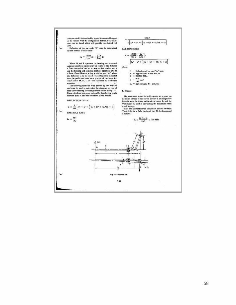
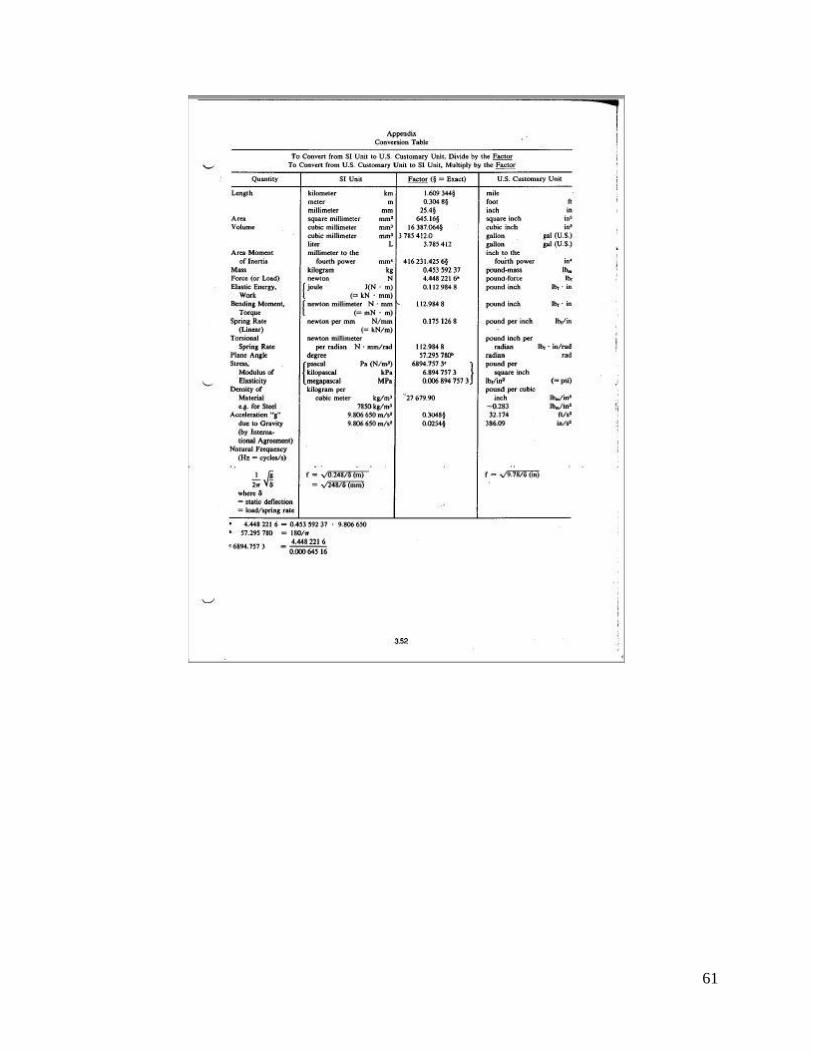
58

59

60
61

62
Appendix 2
ANSYS APDL Program

63

64