design and optimization of fabric-formed beams and … form-finding and finite element analysis,...
TRANSCRIPT

241© 2011 Ernst & Sohn Verlag für Architektur und technische Wissenschaften GmbH & Co. KG, Berlin · Structural Concrete 12 (2011), No. 4
Fabric formwork entails the use of fabrics as the main contactmaterial for a concrete mould. The fabric is either hung or pre-stressed in a supporting falsework frame. Beams or trusses castin fabric formwork are inherently non-prismatic and have beenshown to offer potential for structurally efficient shapes. Thecasting of beams or trusses in fabric formwork is a highly non-lin-ear problem due to the interaction of the fluid concrete with thewoven, prestressed fabric material. Numerical models need to bedeveloped for the engineering of these elements. To this end, it isdemonstrated that it is feasible to integrate manufacturing con-straints in an automatic optimization process. This is achieved bycreating an automated computational framework that includesfabric form-finding and finite element analysis, which operatewithin an optimization process that uses principles from biologi-cal evolution. The results show structurally efficient and manu-facturable beams and demonstrate potential for optimization ingeneral that explicitly includes fabrication considerations.
Keywords: fabric formwork, form-finding, dynamic relaxation, geneticalgorithm, differential evolution
1 Introduction
The concept of casting concrete in fabrics has resurfacedat various times and in different forms over the past 100years [1]. The use of fabric in formworks allows savings onformwork material and results in concrete with unconven-tional aesthetics. Most applications of fabric formworktend to have a clear function that is either structural or ar-chitectural. Structural examples include shell structures(Fig. 1), foundations, revetments and circular columns,whereas architectural examples include fabric-formedwalls and façade panels (Fig. 2), where the fabric is used tocreate a certain surface texture. Fabric-formed structuresthat feature architectural expression while serving a mainloadbearing purpose do exist, but they are few in numberand involve academia for the design. The lack of engineer-ing tools for design and analysis is one reason why the po-tential of fabric-formed structures is seldom translated in-to commercial projects.
A comparison can be drawn with the engineeringpractice of tensile structures. Both often rely on physical
modelling during the initial design stages and requireform-finding software to determine the geometry and sub-sequent stresses at later stages. Several aspects of the de-sign process are therefore similar. It would be good if soft-
Articles
Design and optimization of fabric-formed beams and trusses: evolutionary algorithms and form-finding
Diederik Veenendaal*Jeroen CoendersJan VamberskyMark West
DOI: 10.1002/suco.201100020
* Corresponding author: [email protected]
Submitted for review: 18 April 2011Revised: 14 September 2011Accepted for publication: 14 September 2011
Fig. 1. James de Waller, Church of Christ the King and St. Peter, Bristol,1950 (since demolished), expressive, but entirely shaped by structural con-siderations; reproduced by permission of the “The Architects’ Journal”
Fig. 2. Miguel Fisac, Casa Pascual de Juan en La Moraleja, Madrid, 1975,architectural façade panels, non-loadbearing; reproduced by permission ofFundación Miguel Fisac

ware tools and modelling were to become available forfabric formwork design as well. They would enable engi-neers to derive data on the fabric of a fabric formworksuch as the prestress, stresses and strains during loading,fabric size and possible cutting patterns. Furthermore, theunconventional concrete geometries that result from fab-ric formwork have to be understood and analysed as well.General engineering rules of thumb for structural ele-ments often rely on the assumption that the member isprismatic, which may limit how fabric formwork is ap-plied. Overall, a better understanding of the design and en-gineering of fabric-formed structures is necessary to allowmore complex geometries to be realized without inputfrom academia.
2 Scope of the research and approach
The main objective of this research project was to demon-strate the viability of combining an optimization algo-rithm with manufacturing constraints. The research wascarried out at the Faculty of Civil Engineering and Geo-sciences, Delft University of Technology [14]. Fabric form-work was chosen from current developments in manufac-turing methods because it posed interesting and complexconstraints. The entire automated computational processthat was developed consisted of three main elements: aform-finding algorithm that calculates the shape of theformwork, a structural analysis that evaluates the resultingconcrete element and, finally, an optimization algorithmthat continually improves on the results.
The interaction with the optimization is as follows:the form-finding is driven by the boundary constraints(e.g. fabric supports and prestressing), its results are evalu-ated using finite element analysis and these results arethen used to determine new “evolved” boundary con-straints for the form-finding for a new set of beams.
These three tasks were programmed in a Java frame-work using dynamic relaxation for form-finding and inter-facing with the finite element program ANSYS for struc-tural analysis combined within differential evolution foroptimization (Fig. 3).
242
D. Veenendaal/J. Coenders/J. Vambersky/M. West · Design and optimization of fabric-formed beams and trusses: evolutionary algorithms and form-finding
Structural Concrete 12 (2011), No. 4
Before discussing each element, an overview is givenof existing research on the numerical analysis of fabricformwork and fabric-formed beams to which the softwarewas applied.
3 Existing research
The amount of research on the computational structuralanalysis of fabric-formed elements is very limited. The on-ly example prior to this research concerns the optimiza-tion of fabric-formed panels [2]. A manual iterative proce-dure was developed to achieve an optimum structuralshape for a panel based on its support conditions. Thepanel was analysed in a finite element program andchecked for strength requirements based on the load case.Vrije Universiteit Brussel recently performed studies onthe modelling and shaping of fabric formwork. A softwareprogram for the design and analysis of tensile structures,EASY, was used [3]. Prototypes made for verification in-clude a non-prismatic column and a hyperboloid-like shellstructure. ETH Zurich has used a novel form-finding strat-egy to calculate the fabric and prestressing required to ap-proximate a given target shape for a fabric-formed shell,applied to a hyperbolic paraboloid [4].
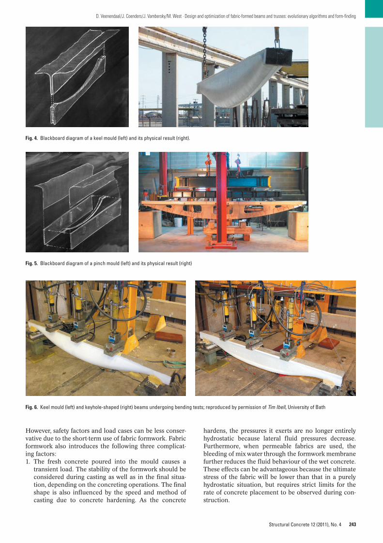
Specific research into fabric-formed beams and truss-es has been performed at three other universities. Variousmethods of manufacturing these elements, such as keeland pinch moulds (Figs. 4 and 5), have been developed atthe University of Manitoba in Canada, where the Centrefor Architectural and Structural Technology is devotedprimarily to research into fabric formwork. Early exam-ples are beams that follow the geometry of the bendingmoment diagram. Later geometries evolved into trusses asattempts were made to reduce material along the neutralaxis of the beam [5]. A related study at the University ofEdinburgh investigated a keel mould-type beam [6]. Sever-al consecutive theses at the University of Bath have ap-proached these methods from an engineering point ofview [7, 8] and research on the topic remains ongoing.Geometries were optimized for shear and bending resis-tance, approximated with a fabric formwork and subse-quently cast to analyse structural response, material sav-ings and labour costs. The ultimate load capacity wascompared with that of a rectangular beam based on thesame maximum top width and maximum depth. Resultsshow concrete material savings of 25 % for a keel mould-type beam and 44 % for a beam with a keyhole-shaped sec-tion (Fig. 6). The disadvantage of the latter beam is thehigher complexity of the formwork required and a corre-sponding increase in labour costs.
4 Form-finding and analysis
The shape of tensioned membrane structures is notknown in advance because it depends on the interactionof boundary conditions, the prestressing of the fabric andthe fabric’s (non-linear) material properties. A calculationprocess called form-finding is therefore required. The de-sign and engineering of fabric formworks poses similarconsiderations and should adhere to the same safety ap-proaches, such as using stress factors instead of load fac-tors (which would change the geometry of the fabric).
FABRICFORMER
Differential Evolution
Dynamic Relaxation
Finite Element Analysis
Fig. 3. Simplified diagram of FabricFormer framework
243
D. Veenendaal/J. Coenders/J. Vambersky/M. West · Design and optimization of fabric-formed beams and trusses: evolutionary algorithms and form-finding
Structural Concrete 12 (2011), No. 4
However, safety factors and load cases can be less conser-vative due to the short-term use of fabric formwork. Fabricformwork also introduces the following three complicat-ing factors:1. The fresh concrete poured into the mould causes a
transient load. The stability of the formwork should beconsidered during casting as well as in the final situa-tion, depending on the concreting operations. The finalshape is also influenced by the speed and method ofcasting due to concrete hardening. As the concrete
hardens, the pressures it exerts are no longer entirelyhydrostatic because lateral fluid pressures decrease.Furthermore, when permeable fabrics are used, thebleeding of mix water through the formwork membranefurther reduces the fluid behaviour of the wet concrete.These effects can be advantageous because the ultimatestress of the fabric will be lower than that in a purelyhydrostatic situation, but requires strict limits for therate of concrete placement to be observed during con-struction.
Fig. 4. Blackboard diagram of a keel mould (left) and its physical result (right).
Fig. 5. Blackboard diagram of a pinch mould (left) and its physical result (right)
Fig. 6. Keel mould (left) and keyhole-shaped (right) beams undergoing bending tests; reproduced by permission of Tim Ibell, University of Bath

2. Some types of fabric formwork introduce rigid ele-ments that push or pull the fabric surface while the fab-ric is still able to slide in-plane. These elements havebeen referred to as “pinch points” or “impactos”, al-though in many cases the membrane is fixed to thesepoints. In terms of the modelling of possible sliding,this requires some type of contact analysis or fluid-structure interaction.
3. Several researchers are experimenting with intentionalwrinkling and folding of the fabric to create new aes-thetics as well as corrugations for buckling resistance.This wrinkling is avoided in typical form-finding proce-dures that seek to find minimal surfaces or surfaces ofmean zero curvature.
For the purposes of this research, the concrete pressurewas assumed to be hydrostatic and wrinkling was not con-sidered. Contact analysis is of direct importance to themodelling of more complex fabric-formed beams and wastaken into account.
5 Dynamic relaxation
Various form-finding algorithms exist that solve the shapeof tensioned membrane structures. The dynamic relax-ation algorithm was used in this case [9, 10]. The methodof dynamic relaxation is a pseudo-dynamic process intime which is used to solve static problems. In otherwords, an analogy is drawn between the static solution ofa given problem and the equilibrium state of dampedstructural motion. The algorithm was originally devisedfor various structural problems and has since been exten-sively applied to tensile structures as well.
In dynamic relaxation, a discretized shape is set inmotion by translating some external load P into an accel-eration of the loaded nodes. This results in motion of thenodes, an oscillation (Fig. 7) that will eventually reach sta-tic equilibrium due to damping of the movements (Fig. 8).The solution that has been reached is one of minimum po-tential energy. The dynamic relaxation method was im-proved by replacing the viscous damping with so-called“kinetic damping” in which the kinetic energy of thewhole system is continuously checked for peaks. Whenev-er such a peak in kinetic energy is detected, all motion isarrested (velocities are set to zero) and the algorithm isrestarted at that geometry (Fig. 9). In general, the subse-quent peaks decrease in value as equilibrium between theexternal loads and the internal elastic strains is ultimatelyachieved.
The following section explains the main formulaeand offers some additional information that was found
244
D. Veenendaal/J. Coenders/J. Vambersky/M. West · Design and optimization of fabric-formed beams and trusses: evolutionary algorithms and form-finding
Structural Concrete 12 (2011), No. 4
necessary for the implementation. The authors have no-ticed that Eqs. (1) and (2) are also known as Leapfrog in-tegration which is closely related to Verlet integration;both are multi-step explicit integration methods for solv-ing dynamic systems. The method equates the residualforces R divided by the lumped mass m (which acts as astiffness) to nodal accelerations and subsequently deter-mines nodal velocities and positions at each iteration:
(1)
(2)
The lumped nodal masses m are a function of the elasticand geometric stiffnesses of the connecting elements (7).The time increment Δt is no more than a step size for thealgorithm. It provides a means of guaranteeing numericalstability and determines the speed at which the algorithmattempts to find a solution. The remaining unknown, theresidual, or out-of-balance, force vector R, is the sum of theexternally applied loads F and the internal member loadsdue to tension stiffening for node i in direction j.
(3)
where the summation of residual forces consists of:
(4)
for each element e. Note that during form-finding, theresidual force vectors should converge to zero until a stateof equilibrium is reached.
Δ ΔΔ
ΔΔ Δ
RT
Lx xij
t t et t
et t k
t tit t+( ) +( )
+( )+( ) +(= − ))⎛
⎝⎜⎞⎠⎟
R F Rijt t
ij ij et t
i e
e n+( ) +( )
=
=
= + ∑Δ ΔΔ ,, 0
x x t Vijt t
ijt
ijt t+( ) +( )= + ⋅Δ ΔΔ 2
V V tR
mijt t
ijt t ij
t
i
+( ) −( )= + ⋅Δ Δ Δ2 2
number of iterations
disp
lace
men
ts
static equilibrium
undamped
Fig. 7. Undamped oscillations; adapted from Lewis [10]
underdamped
overdamped
critically damped
number of iterations
disp
lace
men
ts
Fig. 8. Viscous damping with damped oscillations; adapted from Lewis [10]
kinetic energy peaks
kine
tic e
nerg
y
number of iterations
Fig. 9. Kinetic damping with resetting at kinetic energy peaks; adapted fromLewis [10]

245
D. Veenendaal/J. Coenders/J. Vambersky/M. West · Design and optimization of fabric-formed beams and trusses: evolutionary algorithms and form-finding
Structural Concrete 12 (2011), No. 4
The tension T is determined by the in-plane stiffness,the strain and any initial prestressing.
(5)
The actual material properties of the elements are not re-quired for form-finding as long as the final stress valuesare scaled in order to be physically valid. It was decided tocalculate the stiffness EA as the product of the linearizedmodulus of elasticity Ef, the thickness of the fabric tf andthe inradius r of the neighbouring triangle elements, withEf = 490 N/mm2 and tf = 0.76 mm based on a geotextilefabric [2]. In other words, a cable-net analogy was usedwhich is quite common in membrane engineering andsimplifies the computations by modelling a continuum asa network of bar elements.
At the end of each iteration, the kinetic energy of thecurrent structure is calculated according to conventionalmechanics.
(6)
The algorithm converges under the condition that:– the change in kinetic energy between iterations is suffi-
ciently small, and/or– the change in displacement between iterations is suffi-
ciently small, or
E m Vkt t
i ijt+( ) + 2( )= ⋅ ⎛⎝⎜
⎞⎠⎟∑Δ Δ1
2
2t
TEAL
L L Tet t e
eet t
e e+( ) +( )= −( ) +Δ Δ
00 0
– a maximum number of iterations is reached, i.e. the so-lution was not convergent.
The nodal mass m will determine the inertia of each nodebecause it is subjected to forces. As the process of motionis entirely fictitious, these values need not be realistic. It isnoted that the precise definition of these fictitious massesis trivial because they only influence the degree of conver-gence in each iteration, not the final geometry. However,poorly defined masses may lead to divergence. The nodalmass was defined as the sum of the elastic and geometricstiffnesses:
(7)
The inclusion of contact analysis with some of the rigidparts of the mould had to be added to the algorithm. Spe-cific checks were implemented to control fabric that foldsalong rigid edges of the formwork. Elements that spanacross an edge retain their correct length and use a tem-porary third point at the edge as a reference to check this(Fig. 10). In other words, an element is checked if it spansover the edge. If so, the distances to the edge of the twoconnecting nodes are used as the element length, not thedistance between these nodes. Nodes passing over theedge stay within the plane of the fabric – which now folds– and their residual force vector and velocity vectorchange direction accordingly, using rotation (Fig. 11). The
m t EAL
TL
t EAL
EAL
TLi
e
= ⋅ +⎡
⎣⎢
⎤
⎦⎥ = ⋅ + +
⎡∑Δ Δ2
0
2
0
0
2 2ε
⎣⎣⎢
⎤
⎦⎥∑e
edge mould
corr
ect l
engt
h L
e
edge mouldfabric
fabr
ic
fabric
fabr
ic
temporary node
δ
δ
Fig. 10. Diagram of check and correction for elements that fold over the edge of the mould
u
actual co-ordinates
edge mold
v
vrot
θ
intended co-ordinatesfabric
fabr
ic
Telement
temporary node
û
û
Fig. 11. Diagram of check and corrections for nodes that move over the edge of the mould

angle of the adjacent element currently spanning over theedge can be used for this rotation.
The fabric formwork for a beam consists of several el-ements that, in interaction, determine the ultimate shapeof the mould (Fig. 12). The following variables form thetarget for optimization:• The prestressing forces along the length of the fabric• The edge shape along the top• The keel shape along the bottom• The width of the spacing strip• The location and geometry of the pinch points (im-
pactos)
The first three variables – prestress, edge shape and keelshape – were modelled as symmetric, four-degree (d = 4)Bézier curves along the length of the span in the x direc-tion (Fig. 12). The y value determines the magnitude ofthe prestress, the width between the edges and the heightof the keel. For a four-degree Bézier curve, the formula is:
(8)
and due to symmetry x0 = – x4, y0 = y4, x1 = – x3, y1 = y3and due to the fixed, predefined length of the span x0 = – 1/2 L, x3 = 0
This means that only four variables, y0, x1, y1, y2, re-main to be described for each of the three symmetric Bézi-er curves, resulting in a total of n = 12 variables for opti-mization; these are renamed xj = (x1,..., xn). For theextension to the pinch mould, the spacing strip, a singlevalue, was added later as the thirteenth variable. Thepinch points were defined as three quadrangles with foursets of two coordinates and a certain depth to which theyimpact the fabric. Each quadrangle was mirrored so thatthere could be six pinch points in total. This resulted in 27
where Pxyd
d
d=⎛⎝⎜⎞⎠⎟
B t P t P t t P t t
P
( ) = −( ) + −( ) + −( ) +
+ −0
41
32
2 2
3
1 4 1 6 1
4 1 tt t P t t( ) + ∈⎡⎣ ⎤⎦1 3
44, 0,1
246
D. Veenendaal/J. Coenders/J. Vambersky/M. West · Design and optimization of fabric-formed beams and trusses: evolutionary algorithms and form-finding
Structural Concrete 12 (2011), No. 4
additional variables, n = 40 in total, thus increasing thecomplexity of the model considerably.
6 Structural analysis
Finite element analysis was used within the framework toensure a fully computational and automated approach.The software application ANSYS was used for the finite el-ement model of the resulting fabric-formed beams. Thefabric mesh is first translated into a volume mesh andtransferred to ANSYS for evaluation. In this analysis, eachbeam is subjected to one load case consisting of an evenlydistributed load plus self-weight.
A flexible reinforcement strategy for longitudinal re-inforcement was implemented and tested, but ultimatelynot applied in the final results due to computational de-mands. It was a necessary step, however, in order todemonstrate the feasibility of incorporating non-linear ma-terial behaviour in the overall optimization. The non-lin-ear material behaviour of concrete and steel was modelledwith bilinear stress–strain curves. The reinforcement re-quired was calculated using an approximation method fornon-rectangular cross-sections. This method assumes analternative stress–strain diagram using a fully plastic stressdistribution to avoid complicated calculations. Themethod assumes two reductions to correct large devia-tions from more accurately calculated results: the ultimatestress is reduced to 0.95 ⋅ f′c and the depth of the com-pression zone x to 0.80 ⋅ x (Fig. 13).
The reinforcement is calculated at mid-span and as-sumes the use of passive prestressing steel because pre-stressing tendons are ideal for following every possiblecurvature of the beam. A smeared reinforcement modelprovided by ANSYS, which averages the local amount ofreinforcement per element, is defined by three parameters:the reinforcement ratio and the reinforcement orienta-tion, defined by two angles. These values are calculatedfor discrete sections along the beam and assumed to havea concrete cover along the bottom. Other than the cover,no check was implemented to evaluate the discrete sizing
edge width (Bb)
prestressing (Bc)
keel height (Ba)
symmetric design domain (h × 1/2·b × 1/2·L)
xy
z
Pc,0
Pb,0
Pa,0
Pc,1
Pb,1
Pc,1
Pc,2
Pb,2
Pc,3
Pc,4
Pc,2
Pc,3
Pb,3
Pb,4
Pc,4
edge mould
keel mould
single sheet fabric
concrete volume
spacer width (e.g.=0)
edge width
prestressing
impacto
fluid pressure
spacer width
keel height
Fig. 12. Design domain, variables and result of a keel mould; inset shows variables for a pinch mould

247
D. Veenendaal/J. Coenders/J. Vambersky/M. West · Design and optimization of fabric-formed beams and trusses: evolutionary algorithms and form-finding
Structural Concrete 12 (2011), No. 4
and positioning of the reinforcement. Note that the result-ing reinforcement ratios are very low due to the highstrength of prestressing steel and therefore, with a discretemodel, cracking behaviour may be a relatively importantdesign issue.
For any calculation in finite elements, some type ofelement mesh is required. ANSYS provides two kinds ofautomated unstructured meshing algorithms for meshingcomplex geometries. Both strategies were tested and ap-plied to the beams that the framework automatically gen-erates and sends to ANSYS for evaluation. Unfortunately,both methods resulted in either a significant percentage ofpoorly shaped elements despite mesh improvement algo-rithms, or even failure to mesh the geometry at all. Thepoorly shaped elements distort the analysis results andtherefore the total optimization process. It was decided toapproximate the geometry of the fabric formwork usingcubic elements of equal size, with the meshing pro-grammed outside of ANSYS (Fig. 14), an approach similarto that used in Bi-Directional Evolutionary Structural Op-timization [11]. This results in a less accurate geometry,but keeps the analysis stable and reliable at all times.
7 Optimization problem
The structural analysis is used to evaluate each fabric-formed beam for a single load case of uniformly distrib-uted load plus self-weight. A performance index [11] is cal-culated as inversely proportional to strain energy xvolume. This means that the higher the stiffness of thebeam and the lower its volume, the higher the perfor-mance will be rated. This induces material optimizationwhile retaining load resistance. As the strain energy is de-termined by the size of the applied load, the results of theoptimization are influenced by the load. The results dis-cussed below give an indication of the sensitivity. For non-linear analysis, the external load is applied incrementallyafter self-weight while integrating the performance index.This ensures that the entire load history is taken into ac-count while assessing the performance, rather than evalu-
ating the beam for some arbitrary load, thus reducing thesensitivity of the performance index. No integration isnecessary for linear analysis, which reduces the computa-tional demand. The optimization including the perfor-mance index PI is:
(9)
whereδ displacementsK finite element stiffness matrixn number of variables determining the shape (Fig. 12)
As explained, the mould is described in part by three Bézi-er curves – for the shape of the keel, the edge and the mag-nitude of the prestress – each determined by four coordi-nates. The bound constraints allow these coordinates tobe within one domain distance outside the design domain(e.g. Fig. 12, point Pb,2) in order to be able to describe a va-riety of curves within the domain. Additional inequalityconstraints guarantee that the resulting shape is cut off tostay within the design domain. Indirectly, the form-findingprocess itself is an equality constraint because it calculatesa unique fabric shape in each instance.
The upper and lower bounds dj,U and dj,L of the vari-ables xj are described by the size of the design domainh = 0.8 m, b = 0.3 m, L = 9 m and an ultimate prestressTU = 40 kN/m [2]. The starting parameters for xj,i,0 are ran-domly generated according to Eq. (10) as discussed below.For the pinch mould, the additional variables are all coor-dinates within the design domain, constrained to avoidoverlap and retaining a quadrangular shape.
8 Evolutionary optimization
The overall process of form-finding, analysis and evalua-tion has to be guided by a form of optimization towardsmore optimal geometries. Algorithms already exist that
min ,f xPI
E V K dVdt Vj sT
Vt( ) = = ⋅ ⋅ = ⋅ ⋅∫∫1 ′ ρ δ δ ρ
� �
where x x xj n= ( ) ∈1,......, �
d x
cu=3,5‰ε
1,75‰
N’cu
f’c 0,95f’
c
0,8x
}x
Fig. 13. Approximated stress distribution for non-linear analysis of concrete
Fig. 14. Change in strategy from ANSYS unstructured meshing (left) to approximated cubic meshing (right)

aim to optimize structural material efficiency, but the re-sults, often described as “organic” or “skeletal”, are costlyto build. To produce such complex forms, fabric formworkis one option, but the possibilities this method offers comewith specific constraints due to the fabric involved. Forthis reason, the use of a more general purpose optimiza-tion algorithm was favoured. Differential evolution is suchan algorithm that has the flexibility needed to set up a pro-gram that can include the form-finding process for fabrics,and includes non-structural objectives when optimizingfor material efficiency, both continuous and discrete vari-ables [12]. The reliability and convergence speed of differ-ential evolution has been shown to be promising com-pared with other general optimization algorithms [13].
Differential evolution belongs to the category of evo-lutionary or genetic algorithms. Genetic algorithms useconcepts from biological evolution to create a mathemati-cal method of optimization and frequently use the samevocabulary. Evolution is the process by which differentkinds of living organisms have developed. In this particu-lar case, a collection of fabric-formed beams can be equat-ed to a generation of living organisms. The informationcontained in the genes is nothing more than vectors con-taining variables that describe the fabric formwork. A firstset, or generation, of beams is evaluated and those that ex-hibit superior qualities have a higher likelihood of con-tributing to the properties of a new generation of beams.Each new beam is generated by combining the propertiesof parent beams and changing some variables throughrandom mutation. Eventually, after many generations, ge-netic algorithms find optimal or near optimal solutions. Atypical evolutionary algorithm undergoes the followingsteps, which will be discussed in more detail in this order:– Initialization– Selection– Mutation– Recombination– Evaluation– Termination
The first population can be initialized by any uniform ornon-uniform distribution, depending on what is known inadvance about the (location of) optima. Nevertheless, auniform random distribution was chosen to demonstratethe robustness of the entire framework. In this case, eachvector component j of beam i is chosen randomly betweenits feasible lower and upper bounds U and L. The vectorcomponents are the variables that determine the shape ofthe formwork, as shown in Fig. 12.
(10)
The size of the population is ideally quite large to coverthe range of the solution space, i.e. results in high vari-ance. However, the population size was kept small due tothe computational requirements of the entire framework,but this led to poor performance. The final tests were car-ried out at a compromise of 50 beams per generation.
Selection may take place after evaluating the firstpopulation. For each population member, or target vector,three other vectors are selected to calculate a new recom-bined trial vector against which the target vector is com-
x rand d d dj i j j U j L j L, , , , ,,0 0 1= ( ) ⋅ −( ) +
248
D. Veenendaal/J. Coenders/J. Vambersky/M. West · Design and optimization of fabric-formed beams and trusses: evolutionary algorithms and form-finding
Structural Concrete 12 (2011), No. 4
pared. The three other vectors are called the base vectorxr0 and the random vectors xr1 and xr2. Mutually exclusiveindices are implemented to ensure that all four vectors aredifferent population members. In differential evolution,the analogy with biological evolution becomes tenuous be-cause in evolutionary terms it could be said that in thiscase a child (trial) of three parents is compared with oneof the parents (target) for selection.
A degree of mutation is introduced at this point toavoid convergence to local optima and to increase vari-ance. This is achieved by adding the vector differences ofthe random vectors to the base vector. It is from this strat-egy that differential evolution derives its name. The scalefactor Fs gives the weighted difference between the ran-dom vectors, which added to the base vector gives themutant vector v (Eq. (11), Fig. 15):
(11)
where the scale vector for each vector component j is:
Discrete recombination, better known as crossover, is usedto combine two vectors at a crossover point at a vector in-dex C. Vector components 0 to C-1 are taken from one vec-tor and supplemented with components C to D-1 from theother. The crossover factor Cr determines the probabilitythat crossover occurs (Eq. (12), Fig. 16):
(12)
A value of Cr ≈ 0 produces minimum disruption becausefew mutant components vi,g are crossed, whereas Cr ≈ 1favours a high degree of components from vi,g for the newtrial vector ui,g. A crossover factor Cr = 0.2 is standard, but0.9–0.95 can be used for limited parameter dependence.Low values proved to be more successful and reliable and
ui g j i gj i g
j i gu
v
x, , ,, ,
, ,= =
⎧⎨⎪
⎩⎪( ) ≤if 0,1randj CCr j jrandor
otherwise
=( )
F pow rand q rand qFs j j j
q, , , , ,= ( )( ) = ( ) = −0 1 0 1 1 1
v x x xi g r g s r g r gF, , , ,= + ⋅ −( )0 1 2
d 1,U=
H
vari
able
x2,
i
d2,L
= 0
d 1,L=
0
d2,U
= -½L
variable x1,i
xr1,g
xr0,g
vi,g
xr2,g
F(xr1,g
-xr2,g
)
Fig. 15. Projection of vector components x1 and x2 for randomly chosenbeams r1 and r2 in the solution space

249
D. Veenendaal/J. Coenders/J. Vambersky/M. West · Design and optimization of fabric-formed beams and trusses: evolutionary algorithms and form-finding
Structural Concrete 12 (2011), No. 4
most tests used Cr = 2/D. The last tests for the pinchmould geometries showed a higher dependency on the pa-rameters and therefore used Cr = 0.9.
There are various ways of selecting individuals toform a new generation and to reproduce. Differential evo-lution itself uses one-to-one survivor selection. In thiscase, each parent (target vector x) with index i is com-pared with the child (trial vector u) with the same index(Eq. (13)). The worst-performing vector is discarded. Theadvantage is that, contrary to some other methods, thebest solution so far is always kept and no solution worsethan the worst-so-far is ever chosen. On the downside, thismeans it is possible that a trial vector that is better thanmost of the current population will be rejected if its targetis even better. It became clear that this in fact happensvery often in differential evolution. This is not an issue,however, because this merely means that the populationwill feature a few superior solutions that are the focus ofimprovement while as a whole will never degrade.
(13)
There are various ways of specifying how the differentialevolution algorithm should stop, most obviously when im-provement in the performance becomes minimal. How-ever, in our case no termination criteria were defined, andprogress and termination of the algorithm was carried outmanually based on evaluation of continuous output. Thiswas done to avoid creating a black box because practicaldevelopment of this framework required constant evalua-tion of the results and convergence behaviour as early aspossible, rather than waiting for some specific outcome ofarbitrary accuracy.
9 Results
The entire framework, including form-finding, finite ele-ment analysis and optimization, is shown in Fig. 17 as aflow chart. During development of the software, resultswere continuously generated to improve the model. Initial
xux
u xi g
i g
i g
i g i g,
,
,
, ,+ =
( ) ≤ ( )1
if
otherwis
PI PI
ee
⎧⎨⎪
⎩⎪
results pertained to the keel mould method, whereas finaltests were applied to the pinch mould. One result fromeach method is shown here for discussion. The first exam-ple of the keel mould is shown in Table 1 and Fig. 18. Thespan of all examples is 9 m. The material models for bothfabric and concrete are isotropic, homogenous and linearelastic.
Unfortunately, although the framework proved to befunctional, this early result is actually not very optimal. Arectangular beam of equal volume and maximum depthdeflects less. This can be expected as the concentration ofmaterial shown in Fig. 18 along the neutral axis counter-acts the benefits of the curved longitudinal shape. The rea-son for this result is that the performance index containstwo factors that have not been weighted. The reductionsin volume weighed heavier than the improvements in stiff-ness. As the stiffness, calculated as strain energy, is depen-dent on the load, a higher load would increase the relativeimportance of stiffness and improve the results. Ideally,the program should use non-linear analysis as discussedbecause it would allow evaluation of the entire load histo-ry up to failure. The strain energy would become a lesssensitive value because it would be based on the ultimateload, not an arbitrarily chosen design load. However, dueto limits in computational power, it was decided simply toincrease the load during later trials. The effect of this wasvisible because sections tended to become less slender.One later result for the pinch mould is shown in Table 2and Fig. 19.
This later result is a definite improvement, althoughthe distribution of the impact points is certainly not opti-mal because we would expect a more optimal result to becomparable with a truss, featuring several openings alongthe neutral axis instead of merely two large ones. To inves-tigate the potential material-savings of fabric-formedbeams, this result was compared with a conventional rec-tangular beam and a beam with a parabolic, longitudinalprofile (Fig. 20).
Some optimum exists between the ratio h1/h2 be-cause that would allow the beam to deal with both shearforces and bending moments effectively. Some calcula-
} } }prestress Beziér curve edge shape Beziér curve keel shape Beziér curve
j = 0 1 2 4 5 6 7 8 9 10 11
vi,g
x0,i,g
v1,i,g
x2,i,g
v3,i,g
v4,i,g
x5,i,g
x6,i,g
v7,i,g
x8,i,g
v9,i,g
v10,i,g
v11,i,gu
i,g
xi,g
jrand
= 3
start at
rj ≤ Cr
rj > Cr
Fig. 16. Recombination from existing and mutant beams xj,i,g and vj,i,g to generate trial beam uj,i,g

tions were performed in Maple to calculate the deflectiondue to distributed loading for different values of h1/h2.The calculations are based on energy methods.
The expression for the potential energy for a beam inbending with a uniformly distributed load is:
(14)
Together with M = EIκ and κ(x) = – uxx this becomes
(15)E EI u dx qudxpot xx= ( ) −∫ ∫12
2
E E E M dx qudxpot s p= + = −∫ ∫12κ
250
D. Veenendaal/J. Coenders/J. Vambersky/M. West · Design and optimization of fabric-formed beams and trusses: evolutionary algorithms and form-finding
Structural Concrete 12 (2011), No. 4
where the parabolically shaped beam is defined by
(16)
and
(17)I b h x= ( )( )112
3
h x h h xl
xl( ) = + −⎛
⎝⎜⎞⎠⎟+⎛
⎝⎜⎞⎠⎟1 2 1 2 1 2
For each
population
member
For each
generation
START
END
Is the new
performance index higher
than current one?
Initialize population
Clear memory
Create trial / child vector
Check domain boundaries
Create Bezier curves
Create pinch paths
Resequence pinch paths
No
Yes
Create fabric mesh
Form find the fabric mold mesh
Translate fabric mold mesh to
concrete volume mesh
Test the concrete volume in
finite element analysis
Replace target vector with
new trial / child vector
Have convergence criteria
been met?
Yes
No
No
Dynamic
Relaxation
Fig. 17. Flow chart of FabricFormer framework
Table 1. Results of linear analysis, test No. 33
Stiffness B65 Ec 39394 N/mm2
Concrete volume V 0.49 m3
Mid-span cross-section A 0.102 m2
Maximum depth h 0.648 m
Average width/depth ratio bavg/h = A/h2 0.24 (–)
Average cross-sectional area Aavg = V/L = V/9 0.054 m2
External load and averaged self-weight q = 1500 + ρgAavg 2783 N/m
Deflection at mid-span δ 5.0 mm
Fig. 18. Optimized result for keel mould method, test No. 33
Fig. 19. Optimized result for pinch mould method, test No. 82, and rendering
Table 2. Results of linear analysis, test No. 82
Stiffness B25 Ec 28485 N/mm2
Concrete volume V 0.49 m3
Mid-span cross-section A 0.129 m2
Maximum depth h 0.675 m
Average width/depth ratio bavg/h = A/h2 0.28 (–)
Average cross-sectional area Aavg = V/L = V/9 0.054 m2
External load and averaged self-weight q = 4500 + ρgAavg 5780 N/m
Deflection at mid-span δ 1.7 mm

251
D. Veenendaal/J. Coenders/J. Vambersky/M. West · Design and optimization of fabric-formed beams and trusses: evolutionary algorithms and form-finding
Structural Concrete 12 (2011), No. 4
The displacement is assumed to be:
(18)
This displacement function, assumed to be symmetrical,consists of two parts (Ritz functions): a parabola with anamplitude u1 and a fourth-order polynomial with an am-plitude u2. Both parts fulfil the kinematic boundary condi-tions as required by the minimum potential energymethod. It is noted that this analysis does not provide theexact solution to the beam deflection. A third part couldhave been added to the displacement function but the im-provement to the accuracy of the calculated deflectionswould have been minmal.
For equilibrium, the potential energy needs to be sta-tionary with respect to the deformation parameters.Therefore:
(19a,b)∂∂
=∂∂
=E
u
E
upot pot
1 20 0and
u x u xl
xl
u xl( ) = −⎛
⎝⎜⎞⎠⎟+⎛
⎝⎜⎞⎠⎟+ −⎛⎝⎜
⎞⎠⎟1 21 2 1 2 1 2
22 2
1 2+⎛⎝⎜
⎞⎠⎟
xl
The coefficients u1 and u2 are solved from the latter twoequations. The resulting equation is too long to be shown,but gives the displacement as δ = δ(q, l, E, b, h1, h2). The re-sults of this equation for a beam with load, span and vol-ume equal to those of the fabric-formed beam are plottedin Fig. 21.
The plot reveals an optimum where deflection is12 % less than that of a fully parabolic (h1 = 0) or rectan-gular beam (h2 = 0), from which we can conclude that theoptimum ratio h1/h2 is about 4/6. Another interesting con-clusion is that the difference in deflection of a parabolicbeam is a fraction lower – less than 1 % – than that of arectangular beam with an equal b/hmax ratio. The beamcorresponding to the optimum ratio 4/6 is used for com-parison. The fabric-formed beam is loaded in ANSYS andthe resulting deflection is compared to the rectangularand parabolic beams in Table 3. The analytical calculationof the non-prismatic beam includes only bending deforma-tion; therefore, shear deformation and local deformationsat the supports have been neglected. Due to the slender-ness of the beam, the neglected deformations are expected
h1
h2
l = 9 m b
hmax
=h1 +h
2
Fig. 20. Model of parabolic beam used for comparison
10
15
20
25
30
35
40
defle
ctio
n (m
m)
0
5
0 1/9 2/8 3/7 4/6 1 6/4 7/3 8/2 9/1 inf.
h1/h2 ratio
b/h=0 b/h=1/4 b/h=1/2 b/h=3/4 b/h=1
Fig. 21. Deflection of parabolic beam model depending on b/h and h1/h2 ratios

to be very small. Clearly, the numerical computations doinclude all the deformations possible.
The reduction in volume of the fabric-formed beamis 58 %. The reason why both comparisons in Table 3yield the same savings is that the depth and length arekept constant, and therefore the volume is dependent onone variable only, the width (V = b × h × l = b × const.),and thus is linearly proportional to the deflection. Thecomparison demonstrates that gains from optimizing thelongitudinal shape are smaller than those from optimiz-ing the cross-section. From a structural point of view, thepinch mould is far more interesting to develop than thekeel mould, although the latter is much simpler in termsof formwork.
It is possible to compare these results with a theoret-ical beam of equal cross-sectional area A that shifts all itsmaterial to the outer fibres. This beam has two flangeswhere the depth of the flanges hf approaches zero and thewidth bf infinity, and does not feature a web. Assuming Ato be constant, bh = bfhf. The moment of inertia, using theparallel axis theorem, becomes:
(20)
(21)
The moment of inertia becomes 1/4 · bh3 as opposed to1/12 · bh3, suggesting that for a prismatic beam in bendingthe theoretical lower limit for the volume reduction atequal depth and deflection will be 67 %.
10 Discussion
The emphasis of this research was on the principle ofcombining optimization with manufacturability and thecomputational framework in general as a proof of con-cept, leaving room for development and verification of theform-finding and analysis procedures.
The modelling of the fabric could be improved by in-cluding biaxial and non-linear material behaviour, al-though this is likely to be more appropriate at a laterstage after the general design of the beam has been decid-ed upon. The type of meshing can be adjusted to approx-imate better the fabric geometry and at the same timeprovide a basis for the concrete volume mesh. Also, un-structured meshing generators and refinement providedby ANSYS could not cope adequately within an automat-
limh d
f
I Ad bh h→
= + = ⋅⎛⎝⎜⎞⎠⎟
⎛
⎝⎜⎜
⎞
⎠⎟⎟=
02
2
0 2 12
12
14
bbh bh3 33 112
= ⋅
I I Ad b h Add f f= + = +2 3 2112
252
D. Veenendaal/J. Coenders/J. Vambersky/M. West · Design and optimization of fabric-formed beams and trusses: evolutionary algorithms and form-finding
Structural Concrete 12 (2011), No. 4
ed process of random complex shapes. It is likely that ifsimplified cubic meshes are to be avoided, a significantchallenge remains in terms of automated, flexible dis-cretization, although commercially available mesh-lessmethods show promise in this context. If the relativelycoarse cubic approach is retained, some error estimationwould be appropriate.
The analysis of the concrete can include multipleload cases and also non-linear material behaviour to ac-count for the reinforcement steel. As discussed, this mayalso improve the determination of the performance indexand will have a positive effect on the overall optimization.More generally, the current framework considers neitherthe supporting framework for the fabric nor the require-ments and design of the reinforcement, which is crucialfor assessing the added value of more complex formworkssuch as the pinch mould. It would be worthwhile includ-ing aspects of labour, production and transportation in themodel in order to compare fabric formworks fully withconventional methods.
The authors believe that the most important im-provements can be made in the parametric description ofcomplex moulds, e.g. pinch mould, and appropriate rein-forcement. Related research into modern reinforcement isthe key in this respect. Flexible systems such as fibre andtextile reinforcement are prime candidates for combiningwith fabric-formed concrete as well as the notion of thefabric formwork itself functioning as reinforcement.
11 Conclusions
A computational framework has been created that com-bines automatic structural optimization with manufactur-ing constraints. It has been shown that using a general op-timization algorithm allows these constraints to beintroduced directly. In this respect it differs from typicalexamples of structural optimization that do not includemanufacturability or include it only after optimization iscomplete, i.e. use some form of post-processing. This con-ceptual framework contains specific algorithms for thetasks of general optimization, fabric form-finding and con-crete analysis which are independently interchangeablewith similar algorithms. The constraints from any othermanufacturing process could also be used in this frame-work, replacing the form-finding procedure.
Furthermore, the flexibility of general optimizationalgorithms allows non-structural objectives to be taken in-to account. The framework could therefore be applied tomore appropriate, complex problems that include non-structural objectives, and therefore have outcomes thatare relatively hard to predict based on a priori engineeringjudgement.
The current optimization process converges towardsshapes with a higher performance, defined as the ratio ofstiffness to volume. Inclusion of non-linear material be-haviour for the concrete has been discussed and tested,but the computations proved to be too demanding withinthe scope of this project to be used for the final results.The final results show fabric-formed beams that are opti-mized compared with prismatic beams of rectangularcross-section as well as non-prismatic parabola-shapedbeams of rectangular cross-section, significantly reducing
Table 3. Linear elastic comparison of beams of equal span and maximumdepth
Beam Volume at equal Deflection at equal deflection volume
reference beam 100 % 100 %
parabolic beam 88 % 88 %
fabric-formed beam 42 % 42 %

253
D. Veenendaal/J. Coenders/J. Vambersky/M. West · Design and optimization of fabric-formed beams and trusses: evolutionary algorithms and form-finding
Structural Concrete 12 (2011), No. 4
the amounts of concrete and steel required. The results ex-plicitly include manufacturing information such as theamount and shape of the fabric and distribution of pre-stress.
12 Final remarks
The results of the optimization framework are not verysurprising and could easily have been designed by an engi-neer as a target shape for traditional form-finding. So al-lowing more user interaction is suggested for the furtherdevelopment of design and analysis tools for fabric form-works. An architect or engineer should be able to exertmore control over the geometry, preferably in a real-time,parametric environment. This train of thought is the focusof ongoing research on the computational design of fabricformworks as part of the first author’s doctoral researchcarried out at ETH Zurich. It is believed that such interac-tive tools will contribute to fabric formwork achieving itsfull potential, thus expanding architectural vocabularywith new possibilities and ultimately transforming howpeople view structural concrete.
Acknowledgements
The authors would like to thank dr. ir. Pierre Hoogen-boom, member of the first author’s graduate committee,for his help with the review process of this paper and hisexpertise in structural mechanics.
Notation
A surface areaa accelerationB Bézier curveb widthbf width of flangeCr crossover factorD dimension of vectord limiting valueEf fabric stiffnessEk kinetic energyEp position energy, potential energy of external loadsEpot potential energyE′s deformation or strain energyEA tension stiffnessEI bending stiffnessF externally applied loadFs scale factorg gravity (9.81 N/kg)h depthhf flange thicknessI second moment of areaK stiffness matrixL current element lengthL0 initial element lengthI spanM bending momentm lumped nodal massP pointPI performance indexq distributed load
R residual force T tensionT0 initial tension, or pretensiont timetf fabric thicknessu trial vectorV volumev velocityv mutation vectorx base or trial vectorx position vectorδ displacementκ curvatureρ density
References
1. Veenendaal, D. et al.: History and overview of fabric form-work: using fabric for casting concrete. Structural Concrete3, 2011, pp. 164–177.
2. Schmitz, R. P.: Fabric-formed concrete panel design. Pro-ceedings of 17th Analysis & Computation Specialty Confer-ence 2006 Structures Congress. St. Louis, 2006 (online)available at: <http://www.rpschmitz.com/linked%20media/fabric-formed%20concrete%20panel%20design-sei.pdf>
3. Cauberg, N. et al.: Fabric Formwork for Flexible, Architec-tural Concrete. Proceedings of 5th International Symposiumon Fiber Reinforced Polymer Reinforcement for ConcreteStructures. Sydney, 2009 (online) available at: <http://www.fabricforming.org/images/papers/FabricFormworks_fib2008.pdf>
4. Van Mele, T., Block, P.: A Novel Form-finding Method forFabric Formwork for Concrete Shells. Proceedings of Inter-national Association for Shell & Spatial Structures (IASS)Symposium 2010, Shanghai, 2010.
5. West, M.: Flexible fabric molds for precast trusses. BFT IN-TERNATIONAL Betonwerk + Fertigteil-Technik 72, 10(2006), pp. 46–52.
6. Pedreschi, R. F.: Studies in fabric-cast concrete. Innovation& Research 62 (2005), p. 7.
7. Bailiss, J.: Fabric-Formed Concrete Beams Design andAnalysis. Master’s thesis, University of Bath, 2006.
8. Garbett, J.: Bone Growth Analogy for Optimizing FlexiblyFormed Concrete Beams. Master’s thesis, University of Bath,2008.
9. Barnes, M. R.: Form-finding and Analysis of Tension Struc-tures by Dynamic Relaxation. International Journal of SpaceStructures 14, 2 (1999), pp. 89–104.
10. Lewis. W. J.: Tension structures: form and behaviour.Thomas Telford, London, 2003.
11. Huang, X. et al.: A New Algorithm for Bi-directional Evolu-tionary Structural Optimization. JSME International JournalSeries A (2006).
12. Price, K. V. et al.: Differential evolution: a practical approachto global optimization. Springer, London, 2005.
13. Lampinen, J., Zelinka, I.: Mixed Variable Non-Linear Opti-mization by Differential Evolution. Proceedings of Nos-tradamus ’99, 2nd International Prediction Conference.Zlin, 1999.
14. Veenendaal, D.: Evolutionary optimization of fabric-formedstructural elements. Bridging the gap between computation-al optimization and manufacturability. Master’s thesis, TUDelft, 2008 (online) available at: <http://www.fabricform-ing.org/images/papers/Veenendaal,%20D.,%202008.%20Evolutionary%20Optimization%20of%20Fabric%20Formed%20Structural%20Elements.pdf>

Coenders, Jeroen, Ir., computation leader, Arup, researcher, Delft University of Technology (TU Delft)Faculty of Civil Engineering & GeosciencesBEMNext LaboratoryStevinweg 1Room 6.662628 CN Delft, NetherlandsTel.: +31 20 3058500Fax: +31 20 [email protected]
Veenendaal, Diederik, MSc, doctoral research assistant, ETH ZurichDepartment of ArchitectureInstitute for Technology in ArchitectureWolfgang-Pauli-Strasse 15HIL E 45.38093 Zurich, SwitzerlandTel.: +41 44 633 28 03Fax: +41 44 633 10 [email protected]
254
D. Veenendaal/J. Coenders/J. Vambersky/M. West · Design and optimization of fabric-formed beams and trusses: evolutionary algorithms and form-finding
Structural Concrete 12 (2011), No. 4
West, Mark, Prof., Associate Professor, University of ManitobaCentre for Architectural Structures & TechnologyUniversity of Manitoba Faculty of ArchitectureArch-2 BuildingWinnipeg, MB, R3T 2N2, CanadaTel.: (204) 474-7427Fax: (204) [email protected]
Vambersky, Jan, Prof. Dipl.ing. Em., Delft University of Technology (TU Delft)Faculty of Civil Engineering & GeosciencesDesign & ConstructionStructural & Building EngineeringStevinweg 1Room S2 1.362628CN Delft, NetherlandsTel.: +31 15 [email protected]