design and performance analysis of coreless axial-flux
TRANSCRIPT
Journal of Magnetics 19(3), 273-281 (2014) http://dx.doi.org/10.4283/JMAG.2014.19.3.273
© 2014 Journal of Magnetics
Design and Performance Analysis of Coreless Axial-Flux Permanent-Magnet
Generator for Small Wind Turbines
Dae-Won Chung* and Yong-Min You
Department of Electrical Engineering, Honam University, Gwangju 507-714, Korea
(Received 27 January 2014, Received in final form 22 June 2014, Accepted 1 July 2014)
This paper presents an innovative design for a low-speed, direct-drive, axial-flux permanent-magnet (AFPM)
generator with a coreless stator and rotor that is intended for application to small wind turbine power
generation systems. The performance of the generator is evaluated and optimized by means of comprehensive
3D electromagnetic finite element analysis. The main focus of this study is to improve the power output and
efficiency of wind power generation by investigating the electromagnetic and structural features of a coreless
AFPM generator. The design is validated by comparing the performance achieved with a prototype. The results
of our comparison demonstrate that the proposed generator has a number of advantages such as a simpler
structure, higher efficiency over a wide range of operating speeds, higher energy yield, lighter weight and better
power utilization than conventional machines. It would be possible to manufacture low-cost, axial-flux
permanent-magnet generators by further developing the proposed design.
Keywords : axial-flux permanent-magnet (AFPM), coreless stator, direct-drive wind power generator, low speed,
design optimization
Introduction
There is currently considerably increased interest in
permanent-magnet (PM) generators for use with small
wind turbines because they are compact, highly efficient,
reliable and self-excited. Power generation from the wind
primarily converts energy from the wind into mechanical
energy through the rotating blades of a wind turbine, and
uses the converted mechanical energy to drive a generator
to produce electrical energy. The overall performance of a
wind power generation system is thus very dependent on
the conversion efficiency of its power generator [1, 2].
The axial-flux configuration of a PM generator, with its
disc-type geometry, is easier to integrate into a wind
turbine that is designed for low-speed applications, in
comparison with its radial-flux counterpart. An axial-flux
PM generator (AFPMG) uses high-strength, permanent
magnets to create a magnetic field in the rotor. As there is
no electrical current flowing to the rotor, there is no need
for brushes, which improves reliability. In addition,
AFPMGs can operate at different rotational speeds, so
manufacturers can design wind turbine drivetrains around
their preferred topologies, possibly using a one- or two-
stage gearbox for medium speeds, or even removing the
gearbox altogether to further improve reliability. The
electromagnetic concept of a coreless AFPMG is similar
to that of a radial-flux generator, but the lack of an iron
core removes the attractive forces between the rotor and
stator. The absence of these forces reduces the structural
loads on the generator, so that considerable weight savings
can be realized, even at higher power ratings. As a result
of this lower structural load and lack of iron core, the
coreless configuration eliminates all ferromagnetic material
including the steel laminations that would otherwise be
needed in the stator, and so does not incur any associated
eddy current or hysteresis core losses. By eliminating the
core losses, a coreless-stator AFPMG machine can operate
at a higher efficiency than a conventional machine [3-5].
In the literature, an AFPM motor with a coreless stator
and a Halbach-magnet array rotor with no back irons
have been designed to drive a solar-powered electric
vehicle at a higher efficiency of 96.5% at the rated power
output and at an extremely high-power density [6]. A
plastic multi-disc coreless AFPM motor was proposed to
directly drive the propeller of a stratospheric unmanned
aircraft because of its high efficiency over a wide power
©The Korean Magnetics Society. All rights reserved.
*Corresponding author: Tel: +82-62-940-5494
Fax: +82-62-940-5053, e-mail: [email protected]
ISSN (Print) 1226-1750ISSN (Online) 2233-6656

− 274 − Design and Performance Analysis of Coreless Axial-Flux Permanent-Magnet Generator… − Dae-Won Chung and Yong-Min You
range and impressively low weight [7, 8]. Coreless AFPM
machines are also contenders for many power generation
applications, particularly direct-drive designs, over a wide
range of operating speeds. For instance, coreless AFPM
generators have been investigated for application to low-
speed, direct-coupled wind turbine generators [9], medium-
speed applications such as automotive generators [10],
and high-speed, direct-coupled gas turbine generators for
aerospace applications [11, 12]. However, research into
low-speed AFPM generators for application to low-cost
power platforms is a relatively recent development [13].
To the best of our knowledge, the design and modeling of
a low-speed, modular, direct-drive AFPM generator with
a coreless stator and rotor for wind turbine power gene-
ration has not been reported yet.
This paper proposes a systematic optimal design meth-
odology for an axial-flux permanent-magnet brushless
machine with a coreless stator and rotor for use with
small wind turbines. Both analytical and electromagnetic
3-dimensional finite element analysis (3D FEA) models
are employed to calculate the parameters of the machine
and to further analyze and optimize the generator's perfor-
mance. Finally the design and fabrication of a prototype
are described for testing and to demonstrate how design
will be relatively simple to manufacture.
2. Design of AFPM Generator
2.1. Design Strategy
The proposed generator has double-disc configuration
with two identical rotor discs (field) and a single stator
disc (armature), as shown in Fig. 1. Both the rotor and the
stator are coreless in which they have non-ferromagnetic
cores. The single stator disc is fixed to the frame and is
the stationary part of the machine. The stator coil is a
three-phase, single-layer trapezoidal winding. This is
embedded in a resin or plastic with a high mechanical
strength to form a single stator disc. Similarly, the rotor
discs, consisting of NdFeB rare-earth PMs supported by a
non-magnetic (aluminum or plastic) structure, constitute
the rotating part which is directly connected to the shaft.
This design does not incorporate any ferromagnetic
material in its core and therefore does not incur any cogg-
ing torque effect or any core losses. The basic structure of
the coreless AFPM machine is shown in Fig. 1.
From the view-point of standardizing AFPM generator
manufacturing, the size and physical dimensions of the
motor are the most important factors affecting the machine's
performance and manufacturing cost. For this application,
the design of the generator has to offer higher efficiency
and power outputs despite the physical constraints, through
minor modifications to the materials and components, in
order to avoid performance challenges and to reduce
development cost. Modern computer-aided design is used
to optimize the design parameters for the following
reasons [20]:
− The calculation of the design parameters and the
evaluation of performance are combined and linked to
a large number of options that are characterized by
small changes to the parameters.
− The ability to perform very detailed electromagnetic
and mechanical analysis allows us to confidently
stretch the design to its limits, and avoid the need for a
prototyping and test program that would be expensive
and time-consuming.
Figure 2 shows the design flow and process using
Maxwell 2D/3D® [14]. In the early stages of the design
process, there is a need for strong iteration between the
design requirements and the design outputs.
Fig. 1. (Color online) Basic structure of coreless AFPM
machine. Fig. 2. (Color online) Flow of computer-aided design.

Journal of Magnetics, Vol. 19, No. 3, September 2014 − 275 −
2.2. Analytical Design Approach
2.2.1. Rotor PM Design
The magnetic design model is based on the double-disc,
24-poles AFPM shown in Fig. 3, which is used to
calculate the parameters for the machine and to further
analyze and optimize the machine's performance. The
magnetic flux flows straight across the air-gaps between
the stator and the rotor. The total flux through the same
area of the magnet surfaces is unchanged and the air-gap
flux density is flat and constant in the radial direction.
Considering three-phase machine with 18 windings in a
section of 360 electrical degrees, the magnetic circuit of
one flux loop consists of one and a half windings on each
side of the stator, facing permanent magnets embedded in
the rotor. The magnetic circuit model for one electrical
period for a half-side of the motor is expressed in terms
of the air-gap reluctances, stator magneto-motive forces,
and fluxes through the magnetic circuit [1].
The magnetic flux excited by the PMs per pole is
defined in the literature [1] by Eq. (1).
(1)
where αi is the ratio of the average flux density Bavg to
peak value of the magnetic flux density Bmg in the air-gap,
p is the number of pole pairs, Ri = 0.5Di and Ro = 0.5Do
are the inner and outer radii of the PMs, and
is the PM diameter ratio, respectively.
The equivalent air-gap of the coreless AFPM machine
in Fig. 3(c) is given by Eq. (2).
(2)
where g is the air-gap clearance, tw is the stator winding
axial thickness, hM is the axial height of the PM and μrrec
is the relative recoil permeability of the PM.
2.2.2. Stator Winding Design
A single-layer, non-overlapping type of winding, called
a “trapezoidal winding” as shown in Fig. 3, was adopted
in this design because of its ease of fabrication and
assembly. The assembly of the stator is made possible by
bending the end of the coils by a certain amount, so that
the active conductors lie evenly within the same plane
and the end windings nestle closely together. The wind-
ings are held in position by using a composite material of
epoxy resin and hardener. The distribution factor of the
windings for the fundamental space harmonic [1] is given
by Eq. (3).
(3)
where m1 is the number of phases and z is the coil
phase belt as determined from, and z = Qc/m1F is the
number of stator coils. F is the coil factor that is deter-
Φf = Rin
Rout
∫ αiBmg
2π
2p------rdr = αiBmg
π
2p------ Ro
2Ri
2–( )
= αiBmg
π
8p------Do
21 kd
2–( )
kd = Ri/Ro =
Di/Do
geq = 2 g 0.5twhM
μrrec
-----------+ +⎝ ⎠⎛ ⎞
kg1 =
sinπ
2m1
---------⎝ ⎠⎛ ⎞
z sinπ
2m1z------------
------------------------
Fig. 3. (Color online) Geometry model of coreless AFPM
machine with trapezoidal windings.

− 276 − Design and Performance Analysis of Coreless Axial-Flux Permanent-Magnet Generator… − Dae-Won Chung and Yong-Min You
mined by taking the greatest common divider (GCD) of
the number of poles and coils (F = GCD(20,Qc)). The
pitch factor of the windings for the fundamental space
harmonic is calculated using Eq. (4).
(4)
where θm = 2πp/s1 is the slot pitch angle, and θre is the
electrical angle corresponding to the coil-layer width.
Accordingly, the winding factor for a single-layer non-
overlap winding is the product of the distribution factor
and the pitch factor, i.e.:
(5)
Then pole pitch is 180 electrical degrees in angle and
the coil pitch is between a minimum of 120 and a maximum
of 240 electrical degrees. Accordingly the induced EMF
in each armature coil can be calculated based on the first
harmonic of the flux density as:
(6)
where is the magnetic flux waveform,
N1 is the number of turns in series per phase, and f is the
angular frequency, respectively. The rms value is obtained
by dividing the peak value of the EMF by .
(7)
where is the EMF constant and ns is the
rotational speed. Assuming that at the axial middle of the
stator the flux distribution generated by the armature coils
with current excitations assumes a ‘conical’ shape, as has
been reported in the literature [1, 5]. Therefore, the flux
density is presumed to be constant over the center of the
circular coil and to decrease linearly across the coil.
However, a substantial leakage flux is detected around the
coils because of the relatively large air-gap, which can be
accounted for by using a leakage flux compensation
factor kL = 1.5. Consequently, the coil inductance can be
evaluated using Eq. (8).
(8)
where μ0 is the vacuum permeability, and Ri, Ro are the
circular winding inner and outer radii in Fig. 3(d), respec-
tively. The required minimum average torque developed
by the machine is given by Eq. (9).
(9)
where is the torque constant.
The machine torque density and power density for the
total volume can be defined by Eq. (10) and (11), respec-
tively.
(10)
(11)
where Dt is the total outer diameter of the machine
including the stack outer diameter and the protrusion of
the end windings from the iron stack in the radial
direction, Lt is the total length of the machine including
the stack length and the protrusion of the end winding
from the iron stack in the axial direction, and ωm is the
rotor angular speed.
2.3. Design Requirements
Regardless of the efficiency of the computer software, it
is always important to check the overall performance and
design requirements. The number of poles is mainly
determined by considering the rotational speed of the
rotor and the magnet material and grade. Because of poor
magnet and space utilization, a machine with a small
number of magnet poles would have a much larger dia-
meter than a machine with a larger number of poles but
kp1 = sinπ
2---
2p
s1------⎝ ⎠
⎛ ⎞sin
θre
2------
θre
2------
-------------- = sinθm
2------⎝ ⎠⎛ ⎞
sinθre
2------
θre
2------
--------------
kω1 = kd1 kp1⋅
ef = N1kω1
dΦf1
dt----------- = 2π f N1 k
ω1Φf cos ωt
Φf1 = Φf sin ωt
2
Ef = 2π f N1kω1Φf = 2πpN1kω1Φfns = kEns
kE = 2π N1Φf
L = kLμ0πN1
2
6 geq 2lm+( )----------------------------- 3Ri
22RiRo Ro
2+ +( )
Tr = m1
2------- pN1kω1Φf Ia = kTIa
kT = m1
2------- pN1kω1Φf
Td = Tr
π/4Dt
2Lt
-------------------- = Tr
ωm
π
4---Dt
2Lt
----------------------
Pd = ωmTr
π/4Dt
2Lt
-------------------- = Pr
π
4---Dt
2Lt
---------------
Table 1. Parameters of analysis model for candidate design.
Items Parameters Unit Values
Stator
Average air-gap mm 1.0
No. of windings ea 18
Outer diameter mm 450
Inner diameter mm 285
Coils in each winding turns 92
Rotor
No. of magnets ea 24
Outer diameter mm 450
Inner diameter mm 280
Rotor speed rpm 300
General
Rated voltage V 288
Frequency Hz 120
Phase ea 3
Output power W 2,000
Misc.Temperature rise limits oC 75
Speed range rpm 200 to 800
Journal of Magnetics, Vol. 19, No. 3, September 2014 − 277 −
the same power output. Thus, it is necessary to consider a
configuration with a larger number of poles, which would
increase the eddy current losses and the assembly com-
plexity.
The design requirements for this application are sum-
marized in Table 1. A configuration with 24 poles and 18
windings is chosen because it offers better magnet
utilization with a smaller rotor diameter. Moreover, small,
stranded wires are used to minimize the eddy current
losses. Based on our analytical calculations, a generator is
sized and designed to develop 2 kW at a rated speed of
300 rpm, using off-the-shelf magnets to reduce the proto-
type cost.
3. FE Analysis and Design Optimization
3.1. FE Analysis Model
The modeling process consisted of design calculations
and FEA to predict the performance of the candidate
designs. The dimensions and materials were selected
using the design and modeling procedure proposed by
Miller [9, 14]. By applying Galerkin's method to the
magnet vector potential in the magnetic circuits, the FEA
for the machine is not required to solve this analytically
[15]. Rather, the commercially available Maxwell 3D
software incorporates tools that can achieve this. The
FEA was used to confirm the magnet circuit saturation, as
well as to obtain the back EMF and to calculate the
winding inductances and electromagnetic torque during
dynamic simulation to enable a more accurate design
cycle. Figure 4 shows partial mesh results for the FE
analysis of a physical model of the candidate machine.
Given the symmetry of an AFPM machine, each half
of the machine, relative to the center plane, mirrors the
other half in the axial direction. Thus, it is possible to
model only one-sixth of the machine comprising the rotor
disk, the air-gap clearance, and the stator, as shown in
Fig. 4.
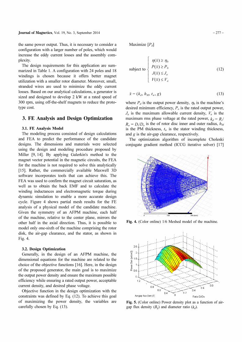
3.2. Design Optimization
Generally, in the design of an AFPM machine, the
dimensional equations for the machine are related to the
choice of the objective functions [16]. Here, in the design
of the proposed generator, the main goal is to maximize
the output power density and ensure the maximum possible
efficiency while ensuring a rated output power, acceptable
current density, and desired phase voltage.
Objective function in the design optimization with the
constraints was defined by Eq. (12). To achieve this goal
of maximizing the power density, the variables are
carefully chosen by Eq. (13).
Maximize [Pd]
subject to (12)
(13)
where Pd is the output power density, η0 is the machine’s
desired minimum efficiency, Po is the rated output power,
Ja is the maximum allowable current density, Va is the
maximum rms phase voltage at the rated power, kd = Ri/
Ro = Di/Do is the of rotor disc inner and outer radius, hM
is the PM thickness, tw is the stator winding thickness,
and g is the air-gap clearance, respectively.
The optimization algorithm of incomplete Choleski
conjugate gradient method (ICCG iterative solver) [17]
η x( ) η0≥
P x( ) P0≥
J x( ) Ja≤
V x( ) Va≤⎩⎪⎪⎨⎪⎪⎧
x = kd, hM, tw, g( )
Fig. 4. (Color online) 1/6 Meshed model of the machine.
Fig. 5. (Color online) Power density plot as a function of air-
gap flux density (Bg) and diameter ratio (kd).

− 278 − Design and Performance Analysis of Coreless Axial-Flux Permanent-Magnet Generator… − Dae-Won Chung and Yong-Min You
was used for this solution. Figure 5 shows a power density
plot as a function of the air-gap flux density obtained
from the variables and the ratio kd for the machine. This
plot shows that the maximum power density (or torque
density), which is found to be 2.56 W/cm3, occurs at an
air-gap flux density of 1.05 T and a diameter ratio of kd =
0.63. At the maximum point, the machine efficiency is
94.3%. Likewise, the maximum power density point can
be obtained. The results, along with the other parameters
of the designed machine, are also listed in Table 1.
3.3. Magnetic Flux Distribution and Generated Power
The candidate design for the machine was verified
according to the flux-linkage versus rotational speed
characteristics at the aligned positions. Figures 6(a) shows
the flux density in the PMs and the windings of a one-
sixth model. Figures 6(b) and (c) show the distribution of
magnetic flux density and flux lines in the air-gap,
respectively. The flux patterns are similar but all the flux
paths obtained by the FEA emanate at right angles to the
pole surface. This was expected from the FEA because of
the imposed constant surface potential and pole surface,
with the magnets virtually in contact, indicate a strong
magnetic field with a significantly large radial component,
especially in close proximity to the pole surface. The
radial component of the air-gap magnetic field is a very
good indication of the shape of the back EMF voltages
generated at the machine terminals. Since the EMF and
inductance of the coil can be computed accurately by the
3D FEA model, machine performance prediction and
design optimization can be achieved with confidence.
The generated power and EMF obtained by the analy-
tical and FEA methods are illustrated in Figures 7 and 8,
respectively. It can be seen that the analytically obtained
power outputs gradually become smaller than the FEA
values when Ri is increasing as shown in Fig. 7. This can
be explained by the EMF errors between the two methods
as shown in Fig. 8. Consequently, a larger flux enhance-
ment factor is highly desirable for the accurate prediction
of the machine performance, because of the greater impact
of the non-sinusoidal radial components on increasing Ri.
Figure 8 also shows that the inductance errors between
Fig. 6. (Color online) Magnetic flux distribution obtained by
FEA.
Fig. 7. (Color online) Power outputs as obtained by analytical
and FEA methods.
Fig. 8. (Color online) EMF errors between analytical and
FEA methods.

Journal of Magnetics, Vol. 19, No. 3, September 2014 − 279 −
two methods are much more stable and smaller than those
for the EMF. It should be noted that the power output of
the machine will first gradually increase and then decrease
as Ri increases and that the analytical and FEA results are
in reasonable agreement.
3.4. FEA Simulation Results
An FEA time transient simulation was performed using
the available design and simulation tools [14]. Figure 9(a)
shows the waveform of the EMF induced in the armature
coils and terminal voltage for each phase. The EMF and
terminal voltages for each phase at rated speed of 300
rpm are approximately 300 V and 288 V in the peak,
respectively. Figure 9(b) shows the time response of the
electromagnetic output power of 2 kW of which value
approaches nearly the output power of generator as seen
in Fig. 12(c). Figure 9(c) shows that the cogging torque,
caused by magnetic saturation in the rotor steel shell,
exists even when there is no stator current in the non-
operating state.
4. Prototyping and Testing of the Machine
Based on the aforementioned design data, a prototype
generator, as shown in Fig. 10, was fabricated for testing
to verify the optimized design and performance. The non-
ferromagnetic holder is shown in Fig. 10. This holder is
attached to the rotor disc with screws. These screws pre-
vent the magnets from moving while the generator is
Fig. 9. (Color online) FEA simulation and measured values at
rated speed (300 rpm).
Fig. 10. (Color online) Prototype coreless AFPM machine.
Fig. 11. (Color online) Test setup consisting of (1) Constructed
generator, (2) Converter, (3) 3-phase induction machine, (4)
Resistive load, and (5) Oscilloscope.

− 280 − Design and Performance Analysis of Coreless Axial-Flux Permanent-Magnet Generator… − Dae-Won Chung and Yong-Min You
rotating. Rare-earth sintered NdFeB magnets are used,
which have a remanent flux density of 0.46 T, and a
maximum allowable working temperature of around 130oC. There are eighteen 3-phase coils that are connected in
series, as described in Table 1. Each coil consists of 92
turns of 1.03 mm diameter wire.
Performance tests on the prototype AFPM machine
were carried out in the laboratory, and the results were
analyzed. The tests focused on power generation, includ-
ing terminal voltage, output power, and efficiency. A re-
configurable water-cooled bank of resistors was configur-
ed into a balanced three-phase load and then connected
across the AFPM machine terminals. An induction machine
was used as the prime mover. Figure 11 shows the experi-
mental setup used for the tests.
The 3D FEA and measured values are compared and
discussed. Figure 12(a) and (b) shows the flux linkage
level and terminal voltage in the air-gap at different speeds,
respectively. The terminal voltage increases linearly with
the speed but the flux level remains constant. Figure 12(c)
and (d) show the variations in the measured output powers
and the efficiency at different speeds, respectively. The
efficiency approaches 94.2% at 300 rpm. Because there
are no core losses, the efficiency of the coreless machine
is higher than that of an iron-core machine normally less
than 90% [1, 7, 8, 11]. The fabricated generator is relative-
ly small. Figure 12 clearly shows that, with an increase in
speed, the efficiency of the machine increases, but this is
not necessarily true for a machine with an iron core. The
test results obtained for the generator are listed in Table 2.
5. Conclusion
Since the overall performance of a wind power gene-
ration system depends largely on the conversion efficiency
of the power generator, a coreless AFPM generator is
proposed that can be easily integrated into a wind turbine
for low-speed applications. The AFPM generators of
direct-drive small wind turbines are usually driven at
relatively low speeds. Therefore, to increase the output
Fig. 12. (Color online) Prototype test result at different rotat-
ing speed.
Table 2. Test results for prototype machine.
Items UnitsPredicted
value
Measured
value
Frequency Hz 120 120
Rated speed rpm 300 300
Terminal Voltage V 221 200
EMF constant V/1000 rpm 1,000 1000
Output Power watts 2,396 2,284
Efficiency % 94.3 92.6

Journal of Magnetics, Vol. 19, No. 3, September 2014 − 281 −
power, a great number of pole-pairs are needed. At these
low speeds, the output power increases, so there is no
need to use more magnets to increase the number of pole-
pairs. Coreless configurations feature no ferromagnetic
material, as they are subject to much lower structural
loads and thus have no need for steel laminations in the
stator. This eliminates the associated eddy currents and
hysteresis core losses. They all have a lower cogging
torque and make less noise while operating. Given the
absence of core losses, a coreless-stator AFPMG machine
operates at a higher efficiency than a conventional machine,
regardless of the rotational speed [18-20]. In addition, the
machine can be made smaller and is cheaper to manu-
facture.
The FE analysis gave results that are acceptable agree-
ment with the design optimization, as regards the air-gap
flux density, the induced phase voltage, the output power,
and the cogging torque. The results of our comparison
demonstrate that the proposed generator has a number of
advantages such as a simpler structure, higher efficiency
over a wide range of operating speeds, higher energy
yield, lighter weight and better power utilization than
conventional machines. This proposed design method will
be applied to multiple-rotor AFPM machines together
with other variable technologies further.
References
[1] F. J. Gieras, R. J. Wang, and M. J. Kamper, Axial Flux
Permanent Magnet Brushless Machines, Springer, 2nd
edition, 304 (2008).
[2] E. Muljadi, C. P. Butterfield, and Yih-huie Wan, IEEE
Trans. Ind. Appl. 35, 831 (1999).
[3] N. F. Lombard and M. J. Kamper, IEEE Trans. Energy
Conversion 14, 1051 (1999).
[4] R. J. Wang, M. J. Kamper, K. V. D. Westhuizen, and J. F.
Gieras, IEEE Trans. Magn. 41, 55 (2005).
[5] U. K. Madawala and J. T. Boys, IEEE Trans. Magn. 41,
2384 (2005).
[6] H. C. Lovatt, V. S. Ramsden, and B. C. Mecrow, Proc.
Inst. Electr. Eng. Electr. Power Appl. 145, 402 (1998).
[7] R. J. Hill-Cottingham, P. C. Coles, J. F. Eastham, F.
Profumo, A. Tenconi, and G. Gianolio, Proc. 36th IEEE
Ind. Appl. Conf. 1634 (2001).
[8] R. J. Hill-Cottingham, P. C. Coles, J. F. Eastham, F. Pro-
fumo, A. Tenconi, and G. Gianolio, Proc. 37th IEEE Ind.
Appl. Conf. 1274 (2002).
[9] T. J. E. Miller, Design of Brushless Permanent Magnet
Machines, University of Glasgow, UK, Magna Physics
Publishing and Clarendon Press, Oxford (1994).
[10] F. Caricchi, F. Crescimbini, and E. Santini, IEEE Trans.
Ind. Appl. 31, 1062 (1995).
[11] R. J. Hill-Cottingham, P. C. Coles, J. F. Eastham, F. Pro-
fumo, A. Tenconi, and G. Gianolio, IEEE Trans. Magn.
38, 3003 (2002).
[12] W. Fei, P. C. K. Luk, J. Jinupun, Proc. IET Power Elec-
tronics, Machines and Drives Conf. 623 (2009).
[13] D.-W. Chung, Trans. of KIEE 61, 1820 (2012).
[14] K. C. Kim and S. K. Lee, Maxwell 2D/3D Training Man-
ual for User Applications, Ansoft Co. User Group, Seoul,
Korea, 1234 (2006).
[15] R. Wang, H. Mohellebi, T. J. Flack, M. J. Kamper, J.
Buys, and M. Feliachi, IEEE Trans. Magn. 38, 1357
(2002).
[16] J. F. Gieras, and M. Wing, New York: Marcel Dekker
Inc. 242 (1997).
[17] Maxim Naumov, Incomplete-LU and Cholesky Precon-
ditioned Iterative Methods Using CUSPARSE and
CUBLAS, NVIDIA CUSPARSE and CUBLAS Librar-
ies, http://www.nvidia.com/object/cuda develop.html
[18] A. Di Napoli, F. Caricchi, F. Crescimbini, and G. Noia,
Proc. International Conference on the Evolution and Mod-
ern Aspects of Synchronous Machine August (1991).
[19] E. Spooner and B. J. Chalmers, IEE Proc. B 139, 497
(1992).
[20] H. G. Kim, Y. T. Seo, and D. K. Lee, Proc. ICEE2002
941 (2002).