design and performance analysis of supersonic inlets · pdf filedesign and performance...
TRANSCRIPT
Page 236
Design and Performance Analysis of Supersonic Inlets Using
Computational Fluid Dynamics
B.Alekhya
Assistant Professor
Dept. of Aerospace Engineering
Marri Laxmam Reddy College of Engineering and
Technology,
Hyderabad.
Neela Manoj Kumar
M.Tech Student
Dept. of Aerospace Engineering
Marri Laxmam Reddy College of Engineering and
Technology,
Hyderabad.
INTRODUCTION
CONE INLET
Although centre-body diffusers and intakes are
more describes at high supersonic Mach numbers
than a pitot-type intakes on account of the
improvement in pressure recovery, they are often
prone to violent prone to violent flows oscillations
for part or all of the mass flow oscillations is
complex but two main types can be recognized.
One we shall call the larger oscillation and the
other the small or „organ pipe‟ oscillations.
According to the explanations offered the large
oscillations is determined by the relative positions
of the centre-body and cowl, and can be avoided
by judicious positioning of one the other. The
small oscillation is caused by resonance of air in
diffuser and can also be avoided by paying
attention to the dimensions of the cowl and centre-
body. An explanation of the mechanisms which
cause these flow oscillations, and suggestions for
avoiding them, will be given in this note.
Unfortunately in many cases stable flow over a
large range of masses flows can only be obtained
by incurring a rise in spillage drag. The
conclusions regarding the flow oscillation were
reached as a result of series of wind-tunnel tests
design solely for the purpose of studying the
oscillations. Most of the tests were made at M=1.8
with two- and three-dimensional ducted bodies.
Some relevant schlieren photographs of
observations of these tests are presented to
substantiate the explanations of the flow
instability. The photographs were taken with an
exposure time of 1/100 sec and oscillations
unstable flows show up as blurred images, the
only clearly defined shock positions being the
limits of the oscillation.
MECHANISMS OF THE LARGE FLOW
OSCILLATION
Below figure shows a typical center-body diffuser
designed to have the conical shock on the cowl lip
at full mass flow for a free-stream Mach number
M; there will then be no spillage drag and the flow
is quiet stable. As the mass flow through the
diffuser is reduced, the flow configuration at the
entry has to adjust itself to satisfy the new
requirement. Fig below shows such a
configuration with air being spilled round the
outside of the cowl with a three-shock
configuration ahead of the diffuser.
Fig1. Centre-body diffuser Full mass flow

Page 237
The flow is modified slightly by the presence of a
boundary layer on the Centre-body which will
separate some extent depending on the strength of
the shock intersecting it and also on the state of
the boundary layer itself. As the mass flow is
reduced the curved shock moves forward to allow
more and more spillage but a point is reached at
which the shock can move no further forward.
This is the shock position which corresponds to
the detached shock which would from ahead of
the cowl if it were a solid body. To make a further
reduction in mass flow through the diffuser entry
the flow configuration ahead of the entry must
now change to some other form.
MECHANISM OF THE SMALL FLOW
OSCILLATION
The previous sections have defined the design of a
diffuser which will be stable as far as the large
oscillation is concerned. Such a diffuser however
is still likely to be susceptible to a small
oscillation. This small oscillation appears to be
caused by resonance of the column of air in the
diffuser which vibrates as in an organ pipe
causing fluctuations of pressure at the month of
the diffuser. This oscillation is illustrated by the
schlieren of fig. the diffuser is operating at no
mass flow in both cases and the only difference in
construction is that the air space between the
Centre body and cowl diffuser but the flow
oscillations ahead of the other in fig1.4 the point
of separation of the from midway along the wedge
is clearly defined. In fig1.4 this separation is not
visible. In fact the point of separation is
oscillations over some length of the wedge and the
resultant picture is accordingly blurred. It may be
noticed that this oscillation did, but this distinction
need not always apply.
The oscillations can be cured by altering the
dimensions of the air space in the diffuser either in
length or breadth which suggests that the exciting
force will only excite a given frequency. The
exact nature of the exciting force is not fully
understood at present but the following
explanation is suggested as being probable. In
organ pipes the resonance of the air column is
sensitive to the length of the air jet playing on the
edge of the pipe, the resonance being produced by
the „edge tone‟ thus produced. In a similar way
the edge tone of the diffuser cowl may be excited
by the separated boundary layer acting as a jet, or
when the vortex sheet from the intersection of the
three shock configuration plays on the lip of the
cowl. The length of the jet in these causes would
be the length of the separated boundary layer or
vortex sheet.
Brief tests were made to see if the oscillation
could be excited by natural frequency oscillations
of the cowl or model supported but in both cases
altering the stiffness did not stabilize the flow.
Further tests are required to examine more closely
this type of oscillation and the mentioned by
which it is excited. In devising these experiments
it is likely that the natural frequency of the air in
the diffuser will be sensitive to temperature
changes and will therefore depend on whether
burning is taking place.
RAMP INLET
This paper provides a method of preliminary
design for a two dimensional, mixed compression,
two ramp supersonic inlets to maximize total
pressure recovery and match the mass flow
demand of the engine. For an on-design condition,
the total pressure recovery is maximized
according to the optimization criterion, and the
Page 238
dimensions of the inlet in terms of ratios to the
engine face diameter are calculated. The
optimization criterion is defined such that in a
system of (n-1) oblique shocks and one normal
shock in two dimensions, the maximum shock
pressure recovery is obtained when the shocks are
of equal strength. This paper also provides a
method to estimate the total pressure recovery for
an off-design condition for the specified inlet
configuration. For an off- design condition can be
estimated. To match the mass flow demand of the
engine, the second ramp angle is adjusted and the
open/close schedule of a bypass door is
determined. The effects of boundary layer are not
considered for the supersonic part of the inlet,
however friction and expansion losses are
considered for the subsonic diffuser.
The inlet is a duct before the engine. Its basic
function is to capture a certain amount of air from
the free stream and supply it to the engine. Most
gas turbine requires the Mach number at engine
face at a moderate subsonic speed, to be about
Mach 0.4. Therefore, for supersonic aircraft with a
gas turbine engine, the inlet will reduce the
supersonic free stream to subsonic speed, and
provided a matched air mass flow rate to the
engine.
The aerodynamic design of a supersonic intake
becomes a critical issue to estimate the overall
performance of an air-breathing propulsion system
which operates at supersonic to hypersonic speeds
and captures the incoming air to supply to
combustor of main engine after compression.
Combined cycle engines have the advantage of
having a single flow passage, where compression
could be achieved through a series of oblique
shocks generated through compression ramps and
internal contraction. This leads to formation of
series of shock waves and expansion waves inside
such intakes. The advantage of such a system is
the simple geometry and possibility of adopting
variable geometry for efficient operation of engine
depending upon the flight operating conditions. A
schematic of flow field for a typical combined
cycle intake is presented in Fig1.5. At the design
condition, the series of compression shocks
generated by the ramps gets reflected at the tip of
the cowl and leads to further compression inside
the intake with the formation of terminal shock at
the throat of the intake after passing through a
series of shocks. Due to the interaction of shock
wave and boundary layer, there exists the
possibility of flow separation inside the intake and
it is likely to reduce the overall performance of the
intake. There also exists the possibility that intake
may not start or intake buzz may occur due to
possible shock oscillations inside the intake. All
these flow phenomena might lead to loss of
performance or damage to the structures. To
alleviate these problems, attempts are being made
by adopting various methods like bleeding,
variable geometry, side wall compression,
perforations, isolators, length of diffuser etc, to
improve the performance of engine. Each of the
methods has its own merits and demerits as it
involves incorporation of additional system e.g.,
installation of bleed system or movement and
control of system, cooling system, etc, for
efficient operation over wide range of operations
of intake. Neale and Lamb1-2 demonstrated the
effect of various geometrical parameters like ramp
angle, side wall, geometry variation, diffuser
length, Reynolds number, etc on an intake
designed for Mach number 2.2, through extensive
and systematic experiments.
The gas turbine engine requires a supply of
uniform high total pressure recovery air for good
performance and operation, thus the quality of the
Page 239
airflow at the engine face will significantly affect
the performance of the engine, especially the total
pressure loss which affects the engine thrust and
consequently the fuel consumption. For1% total
pressure loss, the engine will suffer at least 1%
thrust loss. Therefore, it is important to maximize
the total pressure recovery at the engine face. The
total pressure recovery is the ratio of the total
pressure of the airflow at the engine face to that of
the free stream.
A supersonic inlet has two parts. The supersonic
diffuser for supersonic and the subsonic diffuser,
it is long and heavy. The designer needs to know
the size of the inlet in order to properly account
for it during the conceptual and preliminary
design stage. The designer also needs to estimate
the total pressure recovery at the engine face in
order to estimate the performance of the engine
and the whole aircraft. Therefore, a method is
needed to estimate the size of the supersonic inlet
and the total pressure recovery in the early design
stages. This paper provides such a method for a
2D supersonic inlet.
PROPOSED METHOD AND
IMPLEMENTATION
COMPUTATIONAL METHODOLOGY
The computations are performed using
commercial software CFX which adopts finite
volume approach to solve compressible Reynolds
Averaged Navier Stokes equations with standard
turbulence models. Present computations have
been made adopting k-w turbulence model. The
standard k-w model in CFX is based on the
Wilcox k-w model, which is designed to be
applied throughout the boundary layer and is
applicable to wall bounded flows as well as free-
shear flows. “k-w” turbulent simulations over air
intake reported by Reinartz8, et. al. and
Coratekin13, et al. gave a good comparison with
experimental results at supersonic Mach numbers.
In the present tests, compressibility corrections
were applied and the default model constants were
set. Explicit coupled solver with upwind
discretization scheme for flow and transport
equations was adopted. For faster convergence, 4-
stage multi grid was used. The computational
domain was restricted to the internal duct section
enclosed by ramp surface and the cowl internal
surface only with appropriate boundary conditions
to reduce the computational time. Boundary
conditions at inlet boundary were specified by
stagnation and static pressures corresponding to
supersonic flow of Mach 2.2 with a small
turbulent intensity and viscosity ratio. At the exit,
pressure outlet boundary condition was assigned.
For supersonic outflow, the variables were
extrapolated from the interior cells and for
subsonic outflow, a back pressure was enforced.
No-slip boundary conditions were enforced at all
the solid walls. Computations were made for free
flow (I.e., no back pressure) and with a back
pressure specified by appropriate subsonic out
flow condition.
The preliminary design of the inlet is divided into
the following five subtasks. The first subtask is
the selection of the inlet configuration including
selection of the cross sectional shape of the
supersonic part, selection of compression method,
selection of the number of ramps or oblique
shocks, and selection of the subsonic diffuser. The
second subtask is the determination of the
optimization criteria to maximize the total
pressure recovery. Third is the method to design
the inlet according to the on-design conditions,
including the estimation of the total pressure
recovery and geometric sizes of the inlet. The
fourth subtask compares the optimum on design

Page 240
result with the experimental data and CFD
simulation result. The final subtask is to estimate
the total pressure recovery of the inlet under off
design conditions. The following section outlines
the five subtasks, completion of which provides
the preliminary design of a 2D supersonic inlet
and information on the size of the inlet and
information on the size of the inlet, the maximum
total pressure recovery of the on design condition,
and the estimations of total pressure recovery of
off-design conditions.
SELECTION OF INLET CONFIGURATION
For a supersonic inlet, the free stream is
decelerated to the subsonic engine face entry
speed through a suitable shock system and a
subsonic diffuser. The shock system will
decelerate the flow to a subsonic number, and the
diffuser will further reduce the flow speed to the
engine face entry speed. The design criterion is to
maximize total pressure recovery. At a flight
Mach number of 2.2, a practical number of 95%
total pressure recovery is desired for a long
duration cruise transportation aircraft.
During design of this supersonic inlet
configuration, several sections or tradeoffs have to
be made, including selection of the cross section
shape of the supersonic part, selection of number
of ramp or oblique shocks, and selection of the
subsonic diffuser.
The cross section of the supersonic diffuser can be
annular or rectangular. In general, an annular
supersonic diffuser will have higher total pressure
recovery as long as the free stream flow is aligned
with the centre body axis. However, if the
direction of the flow is at an angle to the axis, this
type of diffuser will be more likely to have such
flow distortion that the engine compressor may
operate close to surge line. In contrast, the two-
dimensional supersonic diffuser is much more
insensitive to non-symmetric flow. Also, a two-
dimensional supersonic diffuser is much more
insensitive to non-symmetric flow. Also, a two-
dimensional supersonic diffuser can provide a
larger variation in inlet flow and is obviously
much simpler in design. For transportation
aircraft, safety is the paramount consideration,
therefore, the two-dimensional cross section shape
is selected for the supersonic diffuser.
Compression selection was based on the idea that
for supersonic Mach numbers up to 1.4-1.6,a pitot
type inlet with a normal shock is considered as the
best choice considering tradeoffs between total
pressure recovery, inlet length and inlet weight. At
high flight Mach numbers up to approximately
2.0, an external compression multi-ramp system is
usually the best choice, again considering total
pressure recovery, length, and weight. With an
external compression inlet, there will be one or
more oblique shocks followed by normal shocks,
which remains outside of the cowl lip. Finally, for
flight Mach numbers above 2.0, a mixed
compression multi-ramp system is considered the
best choice.
A mixed compression method compression
method has a combination of external and internal
oblique shocks followed a normal shock at the
inlet throat. Figure 1 shows three inlets a, b, and c
designed to Mach 2.2 with the same pressure
recovery, but using different compression
methods: inlet A, all external; inlet b, 2 external
oblique shocks,1 internal oblique shock, and 1
internal normal shock; inlet c, 1 external oblique
shock, 2 internal oblique shocks, and 1 internal
normal shock. Although the three inlets in fig
below have the same pressure recovery, they are
different in the following aspects:

Page 241
Fig1.5 types of compression
(1) Self-starting: inlet A is self-starting because of
the external shock, neither B nor C is self- starting
both b and c have to use movable ramps in order
to establish the design shock system, and C is
more difficult than B to establish the design shock
system.
(2) Weight: as the degree of internal compression
increases, the supersonic section of the inlet
becomes longer, and hence heavier.
(3) Boundary layer effects: increased enclosure of
shocks will make the boundary layer effect more
severe.
(4) External drag: as the degree of internal
compression increases, the external line to the
cowl is finer and hence the external wave drag is
less.
The function of the subsonic diffuser is to further
reduce the flow speed after the normal shock to a
lower subsonic Mach number at the engine face.
Given the diffuser entry Mach number and the
engine face speed, the geometric factors of the
diffuser are mainly affected by the duct expansion
angle. Here the geometric factors include the area
ratio of engine face area to entry throat area, and
length. While the supersonic section of the inlet is
two-dimensional in shape, there is a transition
from two –dimensional to circular on the subsonic
section of the inlet is two-dimensional in shape,
there is a transition from two-dimensional to
circular in the subsonic diffuser. Also, a constant
area region is needed to prevent boundary layer
separation at the entrance of the subsonic diffuser.
Integrating the above design decisions together, a
sketch of the whole inlet system is given below in
fig. the double lines originating from point 1, 2, 3
and 4 represent oblique or normal shocks.
Fig1.6 schematic diagram of ramp inlet
THE OPTIMIZATION CREITERON TO
MAXIIZE TOTAL PRESSURE RECOVERY
Instead of using an optimizer with an iterative
procedure, an optimization criterion is used to
determine the ramp angles of the oblique shocks for
maximum pressure recovery of the supersonic section.
The advantage of using optimization criteria is that it is
faster, more accurate, and there is no need of an
optimizer. The optimization criterion is proposed by
Oswatitsch and is described as follows. The maximum
shock pressure recovery is obtained when the shocks
are of equal strength, i.e. The Mach numbers
perpendicular to the individual shocks are equal.

Page 242
Fig1.7 .Multi shock compression for
optimization
DESIGN OF THE INLET ACCORDING TO
ON-DESIGN CONDITIONS
Given the free stream mach number M0, angle of
attack 𝛼, flight altitude H, the normal shock up-stream
Mach numberM4_up,the engine face hub-tip ratio h_t,
the fan face entry Mach number M6, and the ratio of
supersonic diffuser width to engine face diameter
w_d6, the goal of the inlet system design is to
determine ratios of lengths to fan face diameter l1_d6 –
l5_d6, and ratios of heights to fan face diameter h1_d6 –
h5_d6. The Mach number M4_up is given in order to
shock the system; otherwise the number of unknown
variables is more than the number of equations.
Because higher M4_up results in lower Mach number
M4 after the terminal normal shock and thus higher
total pressure loss across, and lower m4 results in lower
total pressure loss in the subsonic diffuser, there is a
value of m4_up that will result in maximum total
pressure recovery. This value of m4_up is found to be
about 1.265 for free stream 2.2 in the example given
later.
SOLUTION OF THE MACH NUMBER AT
DIFFERENT POSITIONS
The inlet is to be designed at the cruise conditions of
flight Mach number 2.2 and flight altitude 55,000 ft. at
the on design point, the oblique shock waves from the
two external ramps intersect at the cowl leading edge,
and the third oblique shock reflects upward to intersect
the junction of the final ramp and the throat section.
This is shown in above figure
The portion of the form Station point 4 to 4a is the
transition zone that ensures the reattachment of the
boundary layer after the normal shock. According to
ref, the slope of this zone should be zero, the cross
section area of this zone should be constant and the
length is selected to be 2 times the height of this
zone...
From station point 4a to 5, the cross section of the duct
transits from a rectangular to a circle and expands
according to ref the expansion angle 2α should be 6-12
degrees to have short length.
CONE PROFILE AND ITS DESIGN
CONSIDERATIONS
Simulated Wind tunnel modeling: The present work is
a wind tunnel modeling in ICEM CFD. A rectangular
domain is designed to simulate on time conditions
prevail at supersonic flow regimes. In ICEM CFD the
geometry model is drafted and meshed. Now this
model is an assemblage of elements, which is
interconnected at nodal points or nodes and together
represents the original body. The meshed model
should be meshed with proper selection of mesh area,
mesh sizes and mesh type. The mesh type we used I
this work is TETRAHEDRAL type: which means

Page 243
there are only tetrahedral elements on the mesh. The
tetrahedral elements give uniformity the structure and
hence the distribution of forces is easy. The model is
checked to ensure connectivity of adjacent
members/elements in assemblage.
The meshed geometry is exported to CFX-PRE and on
time conditions like temperature pressure and velocity
conditions are assigned to the meshed geometry
model. Later the flow conditions assigned meshed
cone is simulated in CFX-POST to obtain results.
PARTS OF WIND TUNNEL MODEL
Domain inlet: It is the inlet for wind tunnel incoming
supersonic flow conditions are assigned in this part.
Domain outlet: it is the outlet part of the wind tunnel.
Domain side walls: these are the side walls of the wind
tunnel for which free slip conditions are assigned.
Center cone: This is the leading edge in the supersonic
inlet which first meets the relative wind.
Inner cylinder: This is attached with outer cylinder
multiple shock reflections and total pressure is
obtained in this section.
Outer lip: Outer lip connects inner cylinder and outer
cylinder it is designed to deviate expansion waves
when subjected to supersonic flow.
Outer cylinder: Outer cylinder connects inner cylinder
and outer lip generally outer cylinder is the outer
casing of the supersonic inlets it is attached to the
pylon of the aircraft.
MESHING
DESCRIPTION OF FINITE ELEMENT
METHOD
Finite element method is a powerful numerical
discretization technique for approximate solution of
continuum mechanics problems or complex problems.
Analytical method of solving many engineering
problems is not possible as it involves mathematical
expressions that give the value of desired unknown
quantity at any location in a body and as a result the
solution can be obtained only for certain simplified
situations for example problems involving complex
structures and boundary conditions, numerical
methods provide approximate but acceptable solutions.
In numerical solutions, a body or a structure is divided
into an equivalent system of smaller bodies or units
with finite degrees of freedom, a process that is termed
as discretization. The assemblage of such units
represents the original body. Each unit is called
element and these elements are interconnected at
joints, which are called nodes or nodal points. Instead
of solving the problem for the entire body in one
operation, an approximate admissible solution is
constructed for each element and the solution
continuity is maintained at the inter element
boundaries. The properties of elements are formulated
and combined to obtain the solution for the entire
structure. This forms the basis of finite element
method.
RESULTS FOR CONE INLET
Fig3.1 cone inlet isometric view
Fig3.2 cone inlet velocity vector plot
Page 244
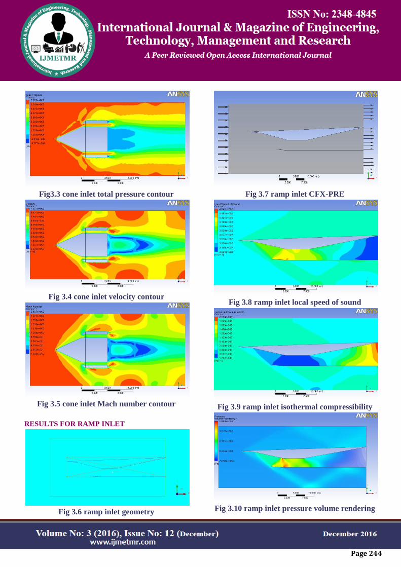
Fig3.3 cone inlet total pressure contour
Fig 3.4 cone inlet velocity contour
Fig 3.5 cone inlet Mach number contour
RESULTS FOR RAMP INLET
Fig 3.6 ramp inlet geometry
Fig 3.7 ramp inlet CFX-PRE
Fig 3.8 ramp inlet local speed of sound
Fig 3.9 ramp inlet isothermal compressibility
Fig 3.10 ramp inlet pressure volume rendering

Page 245
Fig3.11 ramp inlet pressure contour
Fig3.12 ramp inlet total pressure
CONCLUSIONS
CONICAL INLET:
This report has offered an explanation of the large flow
oscillations which can occur with Centre body
diffusers at supersonic speeds and the results of some
wind tunnel tests have been given in support.
With an understanding of the mechanism of the large
flows oscillation it is possible to design a diffuser
which will be stable or in which the limits of stable
operation can be found. Although a diffuser may be
stable as regards the large oscillation it may still be
vulnerable to a small oscillation. The mechanism of
this oscillation is not fully known but methods of
avoiding it in practical cases are suggested.
RAMP INLET:
At high flight Mach numbers up to approximately 2.0,
an external compression multi-ramp system is usually
the best choice, again considering total pressure
recovery, length, and weight. With an external
compression inlet, there will be one or more oblique
shocks followed by a normal shock, which remains
outside of the cowl lip. Finally, for flight Mach
numbers above 2.0, a mixed compression multi-ramp
system is considered the best choice. A mixed
compression method has a combination of external and
internal oblique shocks followed by a normal shock at
the inlet throat.
The maximum pressure recovery is obtained just after
the aft position of the acceleration chamber. Due to the
presence of normal shock at the station 4 the flow in
the acceleration chamber is subsonic speeds we need
to accelerate the flow to velocity range of 0.5-0.8 this
results were achieved at the aft position of the throat
section. The overall length of the supersonic diffuser is
decreased. Thus the maximum pressure recovery is
obtained at the aft of the throat section.
REFERRENCE
1 Goldsmith, E.L, Seddon, J., Practical Intake
Aerodynamic Design, AIAA education series, 1993.
2 Hunecke, K., Jet Engines, Motorbook International,
2003.
3 Mattingly, J. D., et al, Aircraft Engine Design,
second edition, AIAA, 2003.
4 Seddon, J., Goldsmith, E.L., Intake Aerodynamics,
2nd edition, AIAA education series, 1999.
5 Wyatt, D. D., A Review of Supersonic Air Intake
Problems, Air Intake Problems in Supersonic
Propulsion, Pergamon Press,1958.
6 AMES Research Staff, “Equations, Tables, and
Charts for Compressible Flow”, NACA Report 1135,
National Advisory Committee for Aeronautics, 1953.
7 Anderson, J. D., Jr., Fundamentals of Aerodynamics,
3rd edition, Mc Graw Hill, 2001.
8 Crosthwait, E.L., Kennon, I.G., Jr., et al,
“Preliminary design Methodology for Air-Induction
Systems”, Technical ReportSEG-TR-67-1, Systems
Engineering Group, 1967.