design and qualification of the ams-02 flight...
TRANSCRIPT

DESIGN AND QUALIFICATION OF THE AMS-02 FLIGHT CRYOCOOLERS
Kimberly Shirey∗1, Stuart Banks1, Rob Boyle1 and Reuven Unger2
1NASA Goddard Space Flight Center Code 552 – Cryogenics and Fluids Branch Greenbelt, MD 20771, USA 2Sunpower, Inc. 182 Mill Street Athens, OH 45701, USA
ABSTRACT
Four commercial Sunpower M87N Stirling-cycle cryocoolers will be used to
extend the lifetime of the Alpha Magnetic Spectrometer-02 (AMS-02) experiment. The
cryocoolers will be mounted to the AMS-02 vacuum case using a structure that will
thermally and mechanically decouple the cryocooler from the vacuum case. This paper
discusses modifications of the Sunpower M87N cryocooler to make it acceptable for
space flight applications and suitable for use on AMS-02. Details of the flight model
qualification test program are presented.
AMS-02 is a state-of-the-art particle physics detector containing a large superfluid
helium-cooled superconducting magnet. Highly sensitive detector plates inside the
magnet measure a particle’s speed, mass, charge, and direction. The AMS-02
experiment, which will be flown as an attached payload on the International Space
Station, will study the properties and origin of cosmic particles and nuclei including
antimatter and dark matter.
∗ Corresponding author, fax number (301) 286-1637, email address [email protected]
1Copyright © 2005 by Sunpower, Inc. Space Cryogenics Workshop, 25-26 August 2005, Colorado Springs, Colorado
99

Two engineering model cryocoolers have been under test at NASA Goddard since
November 2001. Qualification testing of the engineering model cryocooler bracket
assembly including random vibration and thermal vacuum testing was completed at the
end of April 2005. The flight cryocoolers were received in December 2003. Acceptance
testing of the flight cryocooler bracket assemblies began in May 2005.
KEYWORDS
Stirling (E), Space Cryogenics (F)
AMS-02 INTRODUCTION
AMS-02 is an experiment that will search space for the presence of dark matter,
strange matter and antimatter. A large superconducting magnet cooled with superfluid
helium will bend the path of cosmic particles through a number of highly sensitive
detectors, which then measure the particle’s speed, mass, charge, and direction. The
experiment is currently scheduled to launch no earlier than June 2008, subject to changes
in the shuttle manifest. AMS-02 will be installed on the International Space Station (ISS)
for a minimum three-year mission.
The magnet, superfluid helium tank, layers of super-insulation and 4 vapor-cooled
shields are suspended within a toroidal vacuum case. The vacuum case is machined out
of aluminum with two large support rings on the top and bottom of the outer cylinder.
In an effort to extend the life of the stored cryogen, four Sunpower M87N
Stirling-cycle cryocoolers will be used to cool the outermost vapor cooled shield. To
minimize thermal gradients on the vapor cooled shield, two cryocoolers will be mounted
2Copyright © 2005 by Sunpower, Inc. Space Cryogenics Workshop, 25-26 August 2005, Colorado Springs, Colorado

to ports on the upper vacuum case support ring and the remaining two cryocoolers will be
mounted to the lower vacuum case support ring. The baseline performance requirement
for the four cryocoolers is a total of 9.4 watts of heat lift at 60 K with 400 watts of input
power. Figure 1 shows a view of two of the cryocooler port locations on the AMS-02
vacuum case. The remaining two cryocooler port locations are 180 degrees from its pair
on either support ring.
Figure 1. Cryocooler port locations on AMS-02 vacuum case.
The cryocooler mounting brackets will provide a hermetic seal to the vacuum case
and will thermally and mechanically decouple the cryocooler from the vacuum case. In
order to allow force attenuation using a passive, tuned spring-mass balancer system, the
mount is required to be compliant in the cryocooler thrust axis.
The cold tip of the cryocoolers will be connected via flexible straps to the outer
vapor cooled shield of the dewar. Each strap will span a distance of approximately 100
3Copyright © 2005 by Sunpower, Inc. Space Cryogenics Workshop, 25-26 August 2005, Colorado Springs, Colorado

mm and allow for relative motions no more than 12 mm between the cold tip and the
vapor-cooled shield. Motion of the strap is expected during: launch, vacuum pump
down, magnet cool down, magnet charging and discharging, and in the case of a quench.
Each cryocooler will reject heat to two propylene loop heat pipes, sunk to a direct
condensing zenith octagonal radiator. One quadrant of the radiator will be dedicated to
each cryocooler. The thermal control system will provide a nominal cryocooler operating
temperature between 0°C and +10°C. Survival heaters will be implemented to maintain a
minimum non-operating temperature of -40°C and to assure a minimum turn on
temperature of -10°C. The maximum allowable operating temperature is 40°C.
The cryocoolers will be powered from either of the ISS 124 V DC buses (main
and auxiliary). The electronics must provide the capability of being powered from either
bus and must maintain galvanic isolation between the two buses. The drive electronics
must be capable of supplying 150 W to each cooler. Due to power limitations imposed
by the ISS, the nominal input power will be limited to 100 W. A lower limit of 60 W is
required to insure proper floatation of the gas bearings. A modulated pulse duration drive
was selected for use on AMS-02 for its simplicity, high efficiency, and simple interfacing
to the 120V DC bus.
AMS-02 will be the first space flight mission that will have Stirling-cycle
cryocoolers operating within a substantial steady-state magnetic field. The cryocoolers
will be mounted in locations with a magnetic gradient over the entire length of each
cryocooler and fields as high as 925 Gauss perpendicular to the cryocooler axis and 400
Gauss along the cryocooler axis. Magnetic compatibility testing [1,2,3] conducted on the
4Copyright © 2005 by Sunpower, Inc. Space Cryogenics Workshop, 25-26 August 2005, Colorado Springs, Colorado

engineering model cryocoolers showed the coolers were capable of operating in the
AMS-02 magnetic field with no performance degradation.
SUNPOWER M87N CRYOCOOLER
The Sunpower M87N cryocooler is a modified M87 with enhancements targeted
to better suit the AMS-02 program. The M87, shown in figure 2, is a single free-piston,
integral Stirling-cycle cryocooler designed for high volume manufacturing [4]. The M87
was designed to provide 7.5 watts of cooling at 77 K with 150 watts input power while
operating at a reject temperature of 35°C. This cryocooler has a design lifetime of
>40,000 hours.
Figure 2. Schematic configuration of a linear free piston integral cooler
The M87’s intended use is as an Oxygen liquefier at a patient’s home. Cooler
orientation during operation is vertical with the cold end down. The piston is driven by a
moving-magnet linear motor. The M87 is a true free-piston machine in which the piston
is not axially constrained by mechanical means. Such a configuration simplifies the
mechanical arrangement, which manifests itself in ease of assembly and reduction of
potential side loads. When at rest, the piston can be anywhere along its cylinder. The
5Copyright © 2005 by Sunpower, Inc. Space Cryogenics Workshop, 25-26 August 2005, Colorado Springs, Colorado

controller [5] drives the piston to the axial center position through a start-up sequence,
prior to applying AC to the motor. The voltage applied to the linear motor controls the
piston amplitude. To simplify the electronic driver/controller, the free piston feature was
changed in the M87N design through the use of spring-magnet arrangements [6] that hold
the piston about the center position in any orientation. The permanent magnet segments
are arranged to form a cylinder on a structure of non-magnetic material [7].
Dynamic centering is achieved through a pneumatic network of passages formed
by the piston and cylinder, which allows the working gas to flow between compression
and bounce spaces at predefined locations. The combination of the static magnetic
centering and the pneumatic dynamic centering makes the M87N a true free-piston
machine. A pressure oscillation generated in the compression space drives the displacer
through its rod, which extends through the piston and into the bounce space. Where the
piston relies on the gas spring in the compression space for its resonance, the displacer is
attached to a planar spring through a compliant member [8]. The displacer, containing
the random fiber regenerator, shuttles the gas in-between the cold end and the warm end
heat exchanger. That heat exchanger is made in a form of individual rings that are
thermally shrunk into place in combination with the pressure vessel structure. This
configuration and method of the heat exchanger’s construction [9], results in a cost
effective and manufacturable design.
The gas bearing systems of the commercial cooler were redesigned for the M87N
to provide better performance regardless of orientation. The gas bearings systems are
used to radially center the piston and displacer and thus prevent contact of the moving
parts. The gas bearings are formed [10] into and by the very parts of the piston and
6Copyright © 2005 by Sunpower, Inc. Space Cryogenics Workshop, 25-26 August 2005, Colorado Springs, Colorado

displacer through machining operations, which are highly repeatable, cost effective and
eliminate the need for manual adjustments of the gas bearings.
Cooler vibrations generated by the piston and displacer are countered by a passive
(tuned spring-mass) balancer system. The AMS-02 M87N cryocoolers were
tested/qualified for a 250-hour period before delivery to NASA Goddard and performed
to specification. Figure 3 shows the average measured performance of the six coolers
with a 35oC reject temperature and 150W of input power.
6
7
8
9
10
11
12
13
60 70 80 90 100 110
Average Performance of 6 M87N Final Qalification Test
Lift
(W)
Cold End Temperature (K)
Figure 3. Performance curve of M87N cryocoolers with a 35oC reject
temperature and 150W of input power
CRYOCOOLER QUALIFICATION PROGRAM INTRODUCTION
The AMS-02 project purchased both a standard Sunpower M87 (EM#1) and a
modified M87N (EM#2) for the two engineering models. The engineering models have
7Copyright © 2005 by Sunpower, Inc. Space Cryogenics Workshop, 25-26 August 2005, Colorado Springs, Colorado
been under test at NASA Goddard since November 2001. EM#1 has accumulated just
over 16,000 hours of runtime and EM#2 has accumulated just under 14,000 hours.
NASA Goddard will qualify four Sunpower M87N cryocoolers for space flight
use and two cryocoolers for flight spares on AMS-02. The flight cryocoolers were
received from Sunpower in December 2003. Upon arrival at Goddard, the cryocoolers
were inspected, leak tested, and put through low temperature testing to identify any
problems the coolers might have with low temperature operation. Three of the flight
cryocoolers have begun thermal performance characterization testing and have
accumulated just under 1,000 hours of operation. The remaining three cryocoolers will
be characterized by the end of Fall 2005, after integration in their flight mounting
brackets. Fabrication, inspection and testing of the flight mounting bracket piece parts is
expected to conclude the beginning of October 2005. After the flight cryocoolers have
been integrated with their flight mounting brackets, the qualification program consists of
the following tests:
• Vacuum leak test • Random vibration test of cooler in a compliant mount • Operation tests
- Characterizing base reaction forces - Measure temperature delta at the heat reject collar - Measure the temperature distribution around the cooler
• Measure thermal conductance of the bracket • Thermal cycling test
LEAK CHECK
A helium leak check was performed on all of the flight cryocoolers. This test
measured the rate of helium loss from the cryocooler and assessed the impact of this rate
on the likely performance of the cooler. The helium gas inside the cryocooler, at a
8Copyright © 2005 by Sunpower, Inc. Space Cryogenics Workshop, 25-26 August 2005, Colorado Springs, Colorado

pressure of roughly 16 bar, is essential to produce the required refrigeration. Leakage
from the cryocooler may escape to the experiment environment, or if the leak is in the
coldfinger area, may enter the vacuum space of the AMS-02 Vacuum Case. Helium lost
to the environment causes a reduction in the cryocooler charge pressure, and a loss in
refrigeration. Helium lost into the Vacuum Case will also produce a higher heat leak into
the vapor cooled shields and helium tank. While a relatively large amount of helium loss
to the environment is tolerable, only a relatively small loss of helium into the Vacuum
Case would be tolerable. This test measured the total rate of helium loss from the
cryocooler, and in some cases specifically measured the leak rate in the coldfinger area.
The results of the leak check are provided in Figure 4.
Figure 4. Results of flight model leak tests
While FM 6 has a leak-tight coldfinger, it has the largest total leak rate of all the
flight cryocoolers at 8.5 x 10⁻⁷ sccs. To put this in perspective, the cooler loses a little
less than 1% of its gas per year and would drop from 16 bar to 15 bar over a ten-year
storage period. This cooler would still be operational at this pressure, and could still be a
useful flight candidate.
9Copyright © 2005 by Sunpower, Inc. Space Cryogenics Workshop, 25-26 August 2005, Colorado Springs, Colorado

LOW TEMPERATURE BINDING TEST
All six flight cryocoolers and EM# 2 were put through low temperature testing to
perature operation caused by
therma
e
able 1. All except FM 7
require
Number 20ºC 60 Hz -40ºC 60Hz urrent @
-60ºC 60Hz Current Ratio -60ºC/20ºC
identify any problems the coolers might have with low tem
l contraction of internal components. The test fixture was instrumented with force
transducers to display the motion of the piston on an oscilloscope. The coolers were
tested through a wide temperature range (-60ºC to +20ºC) while capturing the motor
current during startup to look for changes due to binding.
The coolers generally showed an increase in the required starting current as th
operating temperature decreased. The results are shown in T
d less starting current than EM# 2. No indications of rubbing or any abrupt
changes in cooler characteristics were noticed during the test. Some of the coolers
required a change in startup current by a factor of 2 or more.
Table 1: Starting current as a function of temperature
Serial Starting Current @ Starting Current @ Starting C
EM 2 0.157 0.2 0.213 1.4 FM 2 0.073 0.088 0.109 1.5 FM 3 0.075 0.113 0.14 1.9 FM 4 0.045 0.066 0.067 1.5 FM 5 0.091 0.179 0.209 2.3 FM 6 0.037 0.07 0.074 2 FM 7 0.11 0.255 0.277 2.5
QUALIFICATION AND PERFORMANCE VERIFICATION
fter an initial leak check and the low temperature binding test, three of the flight
cryocoolers were prepared for thermal performance characterization. The remaining
three cryocoolers will be characterized by the end of Fall 2005. The coldfingers were
A
10Copyright © 2005 by Sunpower, Inc. Space Cryogenics Workshop, 25-26 August 2005, Colorado Springs, Colorado

instrumented with a heater, to simulate a thermal load, and a Lakeshore silicon diode, and
then wr
in
ber.
by a
-
t, cryocooler body temperature overheat, and loss of vacuum. A
display plemented
the
n
. A
apped with 5 layers of multi-layer insulation. Dallas/Maxim DS18S20 Digital
thermometers were mounted to the cryocoolers’ heat reject and case to monitor
environmental temperatures. Fluid cooled heat exchangers were attached to the
cryocoolers’ heat rejects allowing the reject temperature to be maintained by a laboratory
recirculating chiller. Each cooler was mounted in a fixture that enclosed the coldfinger
a vacuum bonnet allowing operation both in and out of the thermal vacuum cham
The cryocooler mounts were designed to be compliant to allow force attenuation
passive balancer.
Two cryocooler test stations have been developed; each station allows
autonomous operation of four cryocoolers. Each cryocooler is protected with Goddard
developed laboratory cryocooler shutdown electronics that protect against cold tip
temperature overhea
showing the total number of hours accumulated on the cryocooler is im
on the front panel of the electronics. The electronics can be switched between the
Sunpower drive electronics and an external input. The external input allows driving
cooler with an arbitrary waveform function generator and power amplifier combinatio
that can be used to produce sinusoidal or non-standard waveforms; additionally this input
can be used to drive the coolers with the flight type modulated pulse duration drive
data acquisition program, written in LabVIEW, data logs the motor voltage, current,
power, power factor, cryocooler body temperature and cryocooler cold tip temperature
every minute.
11Copyright © 2005 by Sunpower, Inc. Space Cryogenics Workshop, 25-26 August 2005, Colorado Springs, Colorado
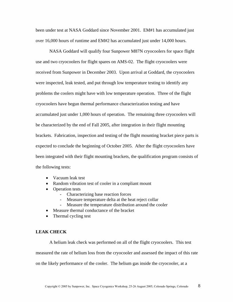
Station 1, as shown in figure 5, allows the coolers to be operated on an optics
bench. Coldfinger vacuum is provided via a manifold and a recirculating chiller allows
cooler operation
between 10ºC and 40ºC. The coolers are initially operated in this station
for 150
Figure 5: Te flight cryocoolers
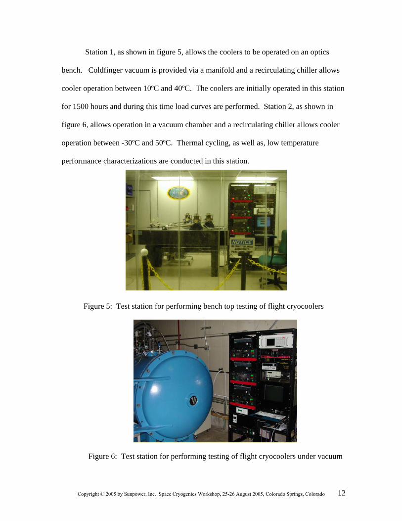
0 hours and during this time load curves are performed. Station 2, as shown in
figure 6, allows operation in a vacuum chamber and a recirculating chiller allows cooler
operation between -30ºC and 50ºC. Thermal cycling, as well as, low temperature
performance characterizations are conducted in this station.
st station for performing bench top testing of
Figure 6: Test station for performing testing of flight cryocoolers under vacuum
12Copyright © 2005 by Sunpower, Inc. Space Cryogenics Workshop, 25-26 August 2005, Colorado Springs, Colorado

A series of baseline performance curves were generated while testing the three
flight cryocoolers under various heat reject temperatures, power levels and thermal loads.
Periodically, a subset of this characterization will be repeated to check for thermal
performance degradation. We have not seen any thermal performance degradation in any
of the flight cryocoolers nor in either of the engineering model cryocoolers. All three
flight coolers tested to date exceed the AMS-02 thermal performance requirement with an
80% margin.
THER
oler
f
ue to laboratory limitations, not all of the thermal cycling took place under
acuum with the cryocooler running. Non-operational thermal cycling took place at
tal chamber where the cryocooler was cycled through
a tempe e
MAL CYCLING TESTS
Thermal cycling tests were performed on EM#2 to put the cooler through the
extreme temperature ranges that could be experienced on orbit. Operational cryoco
thermal cycling took place under vacuum with the cryocooler powered to the nominal on-
orbit power level of 100 W. The cryocooler was cycled through a temperature range o
-20ºC to +40ºC eight times with a minimum dwell time at the extreme temperatures of
four hours. D
v
ambient pressure in an environmen
rature range of –55ºC to +55ºC eleven times with a minimum dwell time at th
extreme temperatures of four hours. A load line was performed after thermal cycling to
verify there was no performance degradation. Thermal cycling will be performed on all
of the flight cryocoolers during the qualification program.
13Copyright © 2005 by Sunpower, Inc. Space Cryogenics Workshop, 25-26 August 2005, Colorado Springs, Colorado

DRIVE ELECTRONICS
The cryocooler electronics are being developed in a combined effort between
NASA Goddard and ETH-Zurich in Switzerland. ETH is responsible for final design and
production. Goddard provided initial development, design and performance verification
of the drive technique [3] and subsequent testing of the ETH
flight type electronics with
n M87N cooler. The cryocoolers will be powered from either of the ISS 124 V DC
The electronics must provide the capability of being powered
from ei e
,
as
res, such as at the cryocooler cold tip and
therma
y
a
buses (main and auxiliary).
ther bus and must maintain galvanic isolation between the two buses. The driv
electronics must be capable of supplying 150 W to each cooler. A modulated pulse
duration drive has been selected. The modulated pulse duration drive uses only a single
‘on’ pulse per half cycle and clamps the motor the remainder of the cycle. The duration
of the ‘on’ pulse is modulated to control input power. This scheme results in a simple
robust design and exceeds 90% efficiency.
ETH provided engineering test model electronics to Goddard for test and
evaluation with an M87N cryocooler. The electronics included the H-bridge driver,
well as, signal conditioning and processing electronics to allow the monitoring of critical
parameters, such as voltages, currents and temperatures. The average values of the DC
supply voltage and current, and the RMS values of the cryocooler drive voltage and
current are calculated. Cryogenic temperatu
l strap, are measured using Cernox sensors. Cernox was selected due to its
immunity to large magnetic fields. Non-cryogenic temperatures, such as the coolers bod
and heat reject, are measured using the Dallas/Maxim DS18S20 Digital thermometer.
14Copyright © 2005 by Sunpower, Inc. Space Cryogenics Workshop, 25-26 August 2005, Colorado Springs, Colorado

These provide 9-bit centigrade temperature measurements between -55°C to +125°C and
are accurate to ±0.5°C over the range of -10°C to +85°C. Each DS18S20 has a uniqu
64-bit serial code, which allows multiple DS18S20s to function on the same 1-Wire bu
External interface and autonomous control capabilities are implemented using a Ma
DS80C390. The DS80C390 is a fast 8051-compatible microprocessor with dual CAN
2.0B controllers.
Initial testing of the ETH engineering test model electronics included verifying
temperature, voltage and current measurements, as well as, the ability to drive a
simulated cryocooler load. Once initial verification was completed, the driver was
connected to an M87N, and efficiency measurements and thermal performance
verification was completed.
Two effici
e
s.
xim
encies were defined for evaluation of the pulse-duration electronics:
inpowerfrequencylfundamentaatpowereffSYSTEM
outpowereffDRIVER
____
__
=
=
inpower
_
_
The driver efficiency is simply defined as the ratio of Power-Out to the Power-In.
The second efficiency, system efficiency, is the ratio of power delivered at the
fundamental drive frequency of the cooler to the power into the drive electronics. The
reason for this second efficiency is that only power delivered at the fundamental drive
frequency produces actual cooling work. Power delivered to the cooler at higher
frequencies generates excess heat and reduces the motor efficiency. The system
15Copyright © 2005 by Sunpower, Inc. Space Cryogenics Workshop, 25-26 August 2005, Colorado Springs, Colorado

efficien
ion of
TION AND DELIVERY SCHEDULE
s is
ryocoolers is the end of October 2006.
light
g of the M87N
ryocoolers for AMS-02.
cy is the figure of merit for evaluating the coupled performance of the drive
electronics and the cryocooler.
At the nominal expected flight power level of 100W to 150W, the system
efficiency was (93 to 94)% and the thermal performance of the cooler was nearly
identical to a sinusoidal drive. Based on these positive results, design and product
the flight boards is in progress.
FLIGHT COOLER INTEGRA
The integration of the flight cryocoolers with their flight mounting bracket
anticipated to begin in October 2005; a 6-month test program would ready the
cryocoolers for delivery to the project by April 2006. The project has indicated that the
earliest need date for the flight c
ACKNOWLEDGMENTS
The authors wish to thank Ed Quinn and Steve Smith of Orbital Science and
Renea’ LaRock of NASA GSFC for their support in all of the engineering and f
model testing and integration for AMS-02. The authors also wish to thank the entire
team at Sunpower who was involved in the design, fabrication, and testin
c
16Copyright © 2005 by Sunpower, Inc. Space Cryogenics Workshop, 25-26 August 2005, Colorado Springs, Colorado

REFERENCES
[1] Breon, S.R. et al., “Operation of A Sunpower M87 Cryocooler in a Magnetic Field”, Cryocoolers 12, Kluwer Academic/Plenum Publishers, New York (2003), pp. 761-769.
[2] Mustafi, S. et al., “Qualifying the Sunpower M-87N Cryocooler for operation in the AMS-02 Magnetic Field”, Cryogenics 2004; Volume 44 (Issue 6-8): pages 575-580.
[3] Banks, S. et al., “AMS-02 Cryocooler Baseline Configuration and EM Qualification Program”, Cryogenics 2004; Volume 44 (Issue 6-8): pages 551-557.
[4] Unger, R.Z., “The Advent of Low Cost Cryocoolers”, Cryocoolers 11, Kluwer Academic/Plenum Publishers, New York (2001), pp. 79-86.
[5] US patent 6,199,381. DC Centering of Free Piston Machine. Issued 3-13-2001. [6] US patent 5,148,066. Linear Generator or Motor With Integral Magnetic Spring.
Issued 9-15-1992. [7] US patent 5,642,088. Magnet Support Sleeve for Linear Electromechanical
Transducer. Issued 6-24-1997. [8] US patent 5,525,845. Fluid Bearing with Compliant Linkage for Centering
Reciprocating Bodies. Issued 6-11-1996. [9] US patent 6,446,336. Heat Exchanger and Method of Constructing Same.
Issued 9-10-2002. [10] US patent 6,293,184. Gas Bearing and Method of Making a Gas Bearing for a
Free Piston Machine. Issued 9-25-2001.
17Copyright © 2005 by Sunpower, Inc. Space Cryogenics Workshop, 25-26 August 2005, Colorado Springs, Colorado