design concept of spliced holed web post-tensioned ...framcos.org/framcos-7/15-14.pdf · a full...
TRANSCRIPT

Fracture Mechanics of Concrete and Concrete Structures -High Performance, Fiber Reinforced Concrete, Special Loadings and Structural Applications- B. H. Oh, et al. (eds)
ⓒ 2010 Korea Concrete Institute, ISBN 978-89-5708-182-2
Design concept of spliced holed web post-tensioned concrete girders
M.Y. Han & Y-S. Jeon Ajou University, Suwon, Korea
S. Choi* & H.K. Kim * Corresponding author, Kookmin University, Seoul, Korea ABSTRACT: Post-tensioned concrete girders have been popular for the superstructures of bridges because of simple design and low maintenance cost. Nevertheless, the traditional I-type PSC girders are limited in their girder length due to allowable stress limitations at each loading step. Prestressing force which is large enough to compensate the total external service loads can't be implemented in the girder at the initial prestressing stage since stresses in concrete which are larger than the allowable stresses should not be developed at subse-quent loading steps. In order to design longer PSC I-type girders, several aspects should be considered and overcome. Three important and different design concepts were implemented in this work to achieve bridge spans up to about 70 meters; 1) Girders are divided into several pieces. Girders can be precast at plants and transported to the construction site without being deterred by transportation problem in Korea. In this way, concrete quality can be ensured, and construction period at the site will be reduced dramatically as well. 2) A numerous number of holes was made in the web of the girder. Some of the anchorage devices were moved from the girder ends into the holes, and the magnitude of negative moment and compressive stresses devel-oped at the girder ends were reduced. 3) Prestressing force was introduced through multiple stages. This con-cept of incremental prestressing overcomes the prestressing force limit restrained by the allowable stresses at each loading stage, and maximizes the magnitude of applicable prestressing force. A full scale girder was fab-ricated. Five pieces of concrete girder members were cast and assembled by post-tensioning to build a 50 me-ter long full scale girder. Test results showed that the spliced holed web post-tensioned concrete girder design concept worked well and would replace steel box girders in competitive span length
1 SCOPE
1.1 Introduction PSC girders are very competitive in the market due to their cost advantage, and many researchers have conducted projects to improve the performance (Alexander et al., 1997, Francis, 1971). Three im-portant design concepts are combined to develop PSC I-type girders that are longer than 50m. Those three concepts are the incremental prestressing method, the introduction of holes in the web, and the splicing method. A full scale girder with the length of 50m was fabricated and tested to verify the per-formance of newly designed girder.
1.2 Incremental prestressing The factor which determines the girder capacity is the allowable stresses of concrete at each loading step. By introducing prestressing forces through multiple steps, larger moment capacity in the girder can be achieved (Han & Hwang, 2002, Han et al,
2003). At the initial stage, prestressing force which compensates only self-weight was introduced. After the concrete deck slab is cast and hardened, second stage prestressing force was applied to compensate the total design loads. In this way, final load carry-ing capacity is increased a lot comparing traditional one-time prestressing method.
1.3 Holes in the web When multiple holes are introduced in the web, the total girder weight is reduced by about 8%. Even though this number is not small, there are other im-portant issues related to the hole. About half of the anchorage devices which were located at girder ends can be moved into the holes. In this way, the magni-tude of compressive stresses developed at girder ends was reduced, and the thickness of web at girder ends can be reduced to the same thickness of web. Prestressing moment introduced through the girder length is more efficient. In other words, negative
moment at girder ends are reduced. And also the girders with holes are aesthetically more attractive.
1.4 Spliced girders Concrete girder segments which are longer than about 20m cannot be delivered conveniently to con-struction site due to transportation difficulties in Ko-rea. When girders are spliced into several pieces several advantages can be achieved. First of all, they can be precast at factory and concrete quality can be ensured. Secondly, transportation problem can be re-solved. Thirdly, some land space at site which is re-quired for girder fabrication is not required. And al-so working hours at site are reduced a lot. After all segments are transported to the bridge construction site, they will be assembled using the first stage of prestressing, and lifted and installed on bridge piers.
2 FABRICATION OF HOLED WEB SPLICED GIRERS
2.1 Girder design and fabrication Total length of the test girder is 50m and it consists of five 10m segments. The height of the girder is 2m, and diameter of a hole is 1m. The center to cen-ter distance between two adjacent holes is 2.5m. The width of deck slab is 2.4m and the thickness is 24cm. It was designed based on the allowable stress design method. But allowable stresses were checked for each separate prestressing stage. Shear was de-signed based on classical beam shear design since no instant design method was available for the current holed web prestressed girder. Self-consolidating concrete was used, and the strength of concrete was 55MPa and 30MPa for girder and deck, respectively. Prestressing wire used was SWPC 7B.
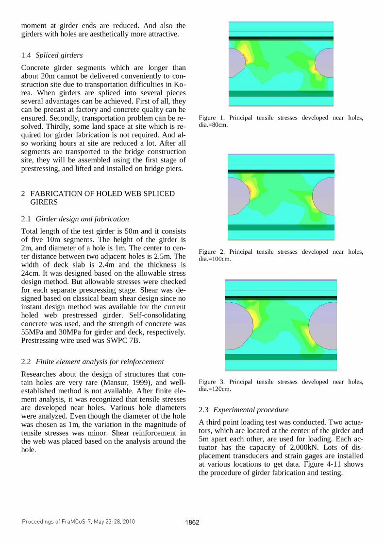
2.2 Finite element analysis for reinforcement Researches about the design of structures that con-tain holes are very rare (Mansur, 1999), and well-established method is not available. After finite ele-ment analysis, it was recognized that tensile stresses are developed near holes. Various hole diameters were analyzed. Even though the diameter of the hole was chosen as 1m, the variation in the magnitude of tensile stresses was minor. Shear reinforcement in the web was placed based on the analysis around the hole.
Figure 1. Principal tensile stresses developed near holes, dia.=80cm.
Figure 2. Principal tensile stresses developed near holes, dia.=100cm.
Figure 3. Principal tensile stresses developed near holes, dia.=120cm.
2.3 Experimental procedure A third point loading test was conducted. Two actua-tors, which are located at the center of the girder and 5m apart each other, are used for loading. Each ac-tuator has the capacity of 2,000kN. Lots of dis-placement transducers and strain gages are installed at various locations to get data. Figure 4-11 shows the procedure of girder fabrication and testing.
Proceedings of FraMCoS-7, May 23-28, 2010
hThD ∇−= ),(J (1)
The proportionality coefficient D(h,T) is called moisture permeability and it is a nonlinear function of the relative humidity h and temperature T (Bažant & Najjar 1972). The moisture mass balance requires that the variation in time of the water mass per unit volume of concrete (water content w) be equal to the divergence of the moisture flux J
J•∇=∂
∂−
t
w (2)
The water content w can be expressed as the sum
of the evaporable water we (capillary water, water vapor, and adsorbed water) and the non-evaporable (chemically bound) water wn (Mills 1966, Pantazopoulo & Mills 1995). It is reasonable to assume that the evaporable water is a function of relative humidity, h, degree of hydration, αc, and degree of silica fume reaction, αs, i.e. we=we(h,αc,αs) = age-dependent sorption/desorption isotherm (Norling Mjonell 1997). Under this assumption and by substituting Equation 1 into Equation 2 one obtains
nscw
s
ew
c
ew
hh
Dt
h
h
ew
&&& ++∂
∂
∂
∂
=∇•∇+∂
∂
∂
∂
− αα
αα
)(
(3)
where ∂we/∂h is the slope of the sorption/desorption isotherm (also called moisture capacity). The governing equation (Equation 3) must be completed by appropriate boundary and initial conditions.
The relation between the amount of evaporable water and relative humidity is called ‘‘adsorption isotherm” if measured with increasing relativity humidity and ‘‘desorption isotherm” in the opposite case. Neglecting their difference (Xi et al. 1994), in the following, ‘‘sorption isotherm” will be used with reference to both sorption and desorption conditions. By the way, if the hysteresis of the moisture isotherm would be taken into account, two different relation, evaporable water vs relative humidity, must be used according to the sign of the variation of the relativity humidity. The shape of the sorption isotherm for HPC is influenced by many parameters, especially those that influence extent and rate of the chemical reactions and, in turn, determine pore structure and pore size distribution (water-to-cement ratio, cement chemical composition, SF content, curing time and method, temperature, mix additives, etc.). In the literature various formulations can be found to describe the sorption isotherm of normal concrete (Xi et al. 1994). However, in the present paper the semi-empirical expression proposed by Norling Mjornell (1997) is adopted because it
explicitly accounts for the evolution of hydration reaction and SF content. This sorption isotherm reads
( ) ( )( )
( ) ( )⎥⎥
⎦
⎤
⎢⎢
⎣
⎡
⎥⎥⎥
⎦
⎤
⎢⎢⎢
⎣
⎡
−
−∞
+
−∞
−=
1110
,1
110
11,
1,,
hcc
ge
scK
hcc
ge
scG
sch
ew
αα
αα
αα
αααα
(4)
where the first term (gel isotherm) represents the physically bound (adsorbed) water and the second term (capillary isotherm) represents the capillary water. This expression is valid only for low content of SF. The coefficient G1 represents the amount of water per unit volume held in the gel pores at 100% relative humidity, and it can be expressed (Norling Mjornell 1997) as
( ) ss
s
vgkc
c
c
vgk
scG αααα +=,1
(5)
where k
cvg and k
svg are material parameters. From the
maximum amount of water per unit volume that can fill all pores (both capillary pores and gel pores), one can calculate K1 as one obtains
( )1
110
110
11
22.0188.00
,1
−⎟⎠
⎞⎜⎝
⎛−∞
⎥⎥⎥
⎦
⎤
⎢⎢⎢
⎣
⎡⎟⎠
⎞⎜⎝
⎛−∞
−−+−
=
hcc
ge
hcc
geGs
ssc
w
scK
αα
αα
αα
αα
(6)
The material parameters k
cvg and k
svg and g1 can
be calibrated by fitting experimental data relevant to free (evaporable) water content in concrete at various ages (Di Luzio & Cusatis 2009b).
2.2 Temperature evolution
Note that, at early age, since the chemical reactions associated with cement hydration and SF reaction are exothermic, the temperature field is not uniform for non-adiabatic systems even if the environmental temperature is constant. Heat conduction can be described in concrete, at least for temperature not exceeding 100°C (Bažant & Kaplan 1996), by Fourier’s law, which reads
T∇−= λq (7)
where q is the heat flux, T is the absolute temperature, and λ is the heat conductivity; in this
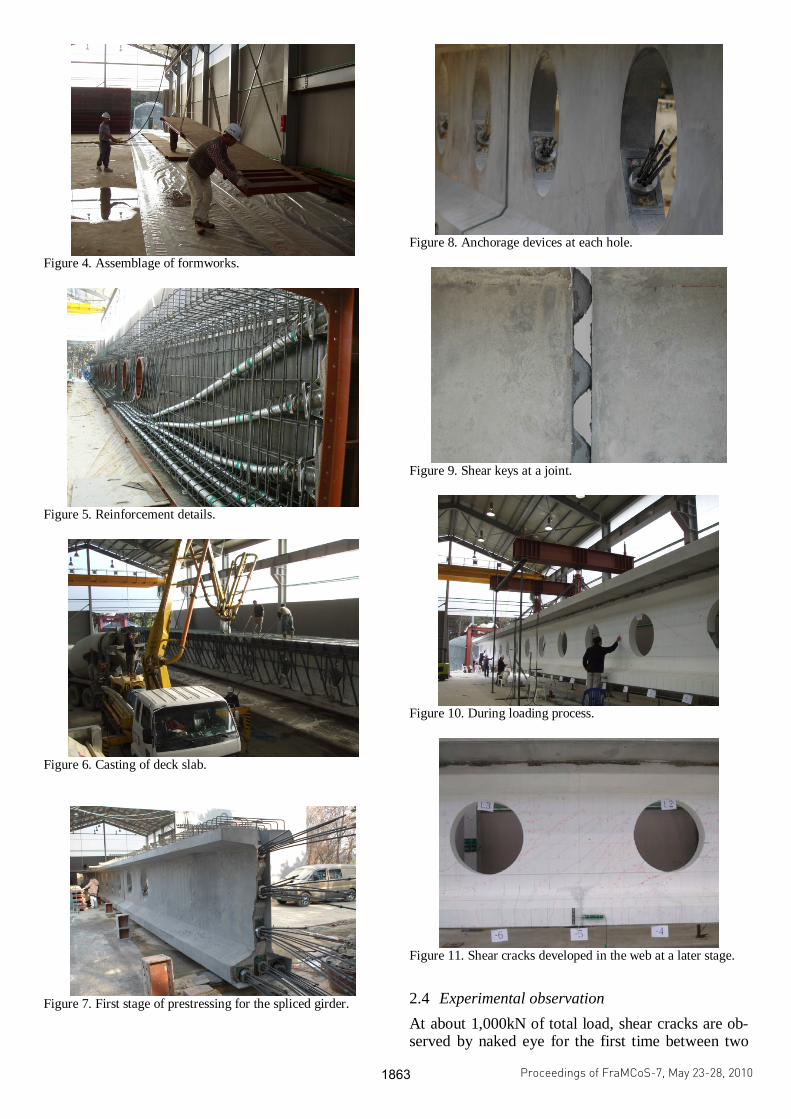
Figure 4. Assemblage of formworks.
Figure 5. Reinforcement details.
Figure 6. Casting of deck slab.
Figure 7. First stage of prestressing for the spliced girder.
Figure 8. Anchorage devices at each hole.
Figure 9. Shear keys at a joint.
Figure 10. During loading process.
Figure 11. Shear cracks developed in the web at a later stage.
2.4 Experimental observation At about 1,000kN of total load, shear cracks are ob-served by naked eye for the first time between two
Proceedings of FraMCoS-7, May 23-28, 2010
hThD ∇−= ),(J (1)
The proportionality coefficient D(h,T) is called moisture permeability and it is a nonlinear function of the relative humidity h and temperature T (Bažant & Najjar 1972). The moisture mass balance requires that the variation in time of the water mass per unit volume of concrete (water content w) be equal to the divergence of the moisture flux J
J•∇=∂
∂−
t
w (2)
The water content w can be expressed as the sum
of the evaporable water we (capillary water, water vapor, and adsorbed water) and the non-evaporable (chemically bound) water wn (Mills 1966, Pantazopoulo & Mills 1995). It is reasonable to assume that the evaporable water is a function of relative humidity, h, degree of hydration, αc, and degree of silica fume reaction, αs, i.e. we=we(h,αc,αs) = age-dependent sorption/desorption isotherm (Norling Mjonell 1997). Under this assumption and by substituting Equation 1 into Equation 2 one obtains
nscw
s
ew
c
ew
hh
Dt
h
h
ew
&&& ++∂
∂
∂
∂
=∇•∇+∂
∂
∂
∂
− αα
αα
)(
(3)
where ∂we/∂h is the slope of the sorption/desorption isotherm (also called moisture capacity). The governing equation (Equation 3) must be completed by appropriate boundary and initial conditions.
The relation between the amount of evaporable water and relative humidity is called ‘‘adsorption isotherm” if measured with increasing relativity humidity and ‘‘desorption isotherm” in the opposite case. Neglecting their difference (Xi et al. 1994), in the following, ‘‘sorption isotherm” will be used with reference to both sorption and desorption conditions. By the way, if the hysteresis of the moisture isotherm would be taken into account, two different relation, evaporable water vs relative humidity, must be used according to the sign of the variation of the relativity humidity. The shape of the sorption isotherm for HPC is influenced by many parameters, especially those that influence extent and rate of the chemical reactions and, in turn, determine pore structure and pore size distribution (water-to-cement ratio, cement chemical composition, SF content, curing time and method, temperature, mix additives, etc.). In the literature various formulations can be found to describe the sorption isotherm of normal concrete (Xi et al. 1994). However, in the present paper the semi-empirical expression proposed by Norling Mjornell (1997) is adopted because it
explicitly accounts for the evolution of hydration reaction and SF content. This sorption isotherm reads
( ) ( )( )
( ) ( )⎥⎥
⎦
⎤
⎢⎢
⎣
⎡
⎥⎥⎥
⎦
⎤
⎢⎢⎢
⎣
⎡
−
−∞
+
−∞
−=
1110
,1
110
11,
1,,
hcc
ge
scK
hcc
ge
scG
sch
ew
αα
αα
αα
αααα
(4)
where the first term (gel isotherm) represents the physically bound (adsorbed) water and the second term (capillary isotherm) represents the capillary water. This expression is valid only for low content of SF. The coefficient G1 represents the amount of water per unit volume held in the gel pores at 100% relative humidity, and it can be expressed (Norling Mjornell 1997) as
( ) ss
s
vgkc
c
c
vgk
scG αααα +=,1
(5)
where k
cvg and k
svg are material parameters. From the
maximum amount of water per unit volume that can fill all pores (both capillary pores and gel pores), one can calculate K1 as one obtains
( )1
110
110
11
22.0188.00
,1
−⎟⎠
⎞⎜⎝
⎛−∞
⎥⎥⎥
⎦
⎤
⎢⎢⎢
⎣
⎡⎟⎠
⎞⎜⎝
⎛−∞
−−+−
=
hcc
ge
hcc
geGs
ssc
w
scK
αα
αα
αα
αα
(6)
The material parameters k
cvg and k
svg and g1 can
be calibrated by fitting experimental data relevant to free (evaporable) water content in concrete at various ages (Di Luzio & Cusatis 2009b).
2.2 Temperature evolution
Note that, at early age, since the chemical reactions associated with cement hydration and SF reaction are exothermic, the temperature field is not uniform for non-adiabatic systems even if the environmental temperature is constant. Heat conduction can be described in concrete, at least for temperature not exceeding 100°C (Bažant & Kaplan 1996), by Fourier’s law, which reads
T∇−= λq (7)
where q is the heat flux, T is the absolute temperature, and λ is the heat conductivity; in this

holes. Some stains near a hole showed large jump in deformation at about 1,900kN. But some strain gag-es attached on vertical stirrups showed sudden in-crease from about 800kN (Fig. 14). Factored shear load from the design live load was about 400kN.
The neutral axis started to move up after about 1,400kN (Fig. 13), which means large amount of flexural cracks formed at this stage. But the hairline flexural cracks observed by naked eye started from as early as 1,000kN.
Figure 12. Load displacement curves.
Figure 13. Longitudinal strains at flanges.
Figure 14. Steel strains at vertical stirrups.
Figure 15. Steel strains near holes.
Final failure was shear failure for the current
girder design. Even though current reinforcing ar-rangement satisfies design load, flexural failure can be ensured when horizontal and vertical reinforce-ments are increased more to increase the shear resis-tance for the area between two holes.
3 CONCLUSIONS
Three innovative design concepts are combined for the design of I-type PSC girders to achieve long span length that is more than 50m.
1) Unified girder design concept that combines the holed web concept, the incremental prestressing method, and the splicing girder method is very promising in overcoming various construction issues such as concrete quality assurance, traffic problem, and maximizing the performance of girder design.
2) Splicing method solves several issues including transportation problem, quality assurance of concrete, and the usage of high strength self-consolidating concrete. The construction period at site also reduces significantly.
3) Negative moment can be introduced more efficiently in the girder if some anchorages can be removed from the girder ends for simple span bridge design, and moved into the holes. Consequently, thick end diaphragm can be reduced too.
4) Since the incremental prestressing method develops concrete stresses sufficient only enough to compensate each loading stage, longer span length can be achieved with the same girder depth.
5) Current test girder was designed to satisfy the DL-24 live load (similar to AASHTO truck load) of Korean Highway Bridge Design Speicification. But, more shear reinforcement is required in the web in order to ensure ductile flexural failure.
Holed web prestressed concrete girder design is a revolutionary design method that has many advantages against conventional I-type concrete
Proceedings of FraMCoS-7, May 23-28, 2010
hThD ∇−= ),(J (1)
The proportionality coefficient D(h,T) is called moisture permeability and it is a nonlinear function of the relative humidity h and temperature T (Bažant & Najjar 1972). The moisture mass balance requires that the variation in time of the water mass per unit volume of concrete (water content w) be equal to the divergence of the moisture flux J
J•∇=∂
∂−
t
w (2)
The water content w can be expressed as the sum
of the evaporable water we (capillary water, water vapor, and adsorbed water) and the non-evaporable (chemically bound) water wn (Mills 1966, Pantazopoulo & Mills 1995). It is reasonable to assume that the evaporable water is a function of relative humidity, h, degree of hydration, αc, and degree of silica fume reaction, αs, i.e. we=we(h,αc,αs) = age-dependent sorption/desorption isotherm (Norling Mjonell 1997). Under this assumption and by substituting Equation 1 into Equation 2 one obtains
nscw
s
ew
c
ew
hh
Dt
h
h
ew
&&& ++∂
∂
∂
∂
=∇•∇+∂
∂
∂
∂
− αα
αα
)(
(3)
where ∂we/∂h is the slope of the sorption/desorption isotherm (also called moisture capacity). The governing equation (Equation 3) must be completed by appropriate boundary and initial conditions.
The relation between the amount of evaporable water and relative humidity is called ‘‘adsorption isotherm” if measured with increasing relativity humidity and ‘‘desorption isotherm” in the opposite case. Neglecting their difference (Xi et al. 1994), in the following, ‘‘sorption isotherm” will be used with reference to both sorption and desorption conditions. By the way, if the hysteresis of the moisture isotherm would be taken into account, two different relation, evaporable water vs relative humidity, must be used according to the sign of the variation of the relativity humidity. The shape of the sorption isotherm for HPC is influenced by many parameters, especially those that influence extent and rate of the chemical reactions and, in turn, determine pore structure and pore size distribution (water-to-cement ratio, cement chemical composition, SF content, curing time and method, temperature, mix additives, etc.). In the literature various formulations can be found to describe the sorption isotherm of normal concrete (Xi et al. 1994). However, in the present paper the semi-empirical expression proposed by Norling Mjornell (1997) is adopted because it
explicitly accounts for the evolution of hydration reaction and SF content. This sorption isotherm reads
( ) ( )( )
( ) ( )⎥⎥
⎦
⎤
⎢⎢
⎣
⎡
⎥⎥⎥
⎦
⎤
⎢⎢⎢
⎣
⎡
−
−∞
+
−∞
−=
1110
,1
110
11,
1,,
hcc
ge
scK
hcc
ge
scG
sch
ew
αα
αα
αα
αααα
(4)
where the first term (gel isotherm) represents the physically bound (adsorbed) water and the second term (capillary isotherm) represents the capillary water. This expression is valid only for low content of SF. The coefficient G1 represents the amount of water per unit volume held in the gel pores at 100% relative humidity, and it can be expressed (Norling Mjornell 1997) as
( ) ss
s
vgkc
c
c
vgk
scG αααα +=,1
(5)
where k
cvg and k
svg are material parameters. From the
maximum amount of water per unit volume that can fill all pores (both capillary pores and gel pores), one can calculate K1 as one obtains
( )1
110
110
11
22.0188.00
,1
−⎟⎠
⎞⎜⎝
⎛−∞
⎥⎥⎥
⎦
⎤
⎢⎢⎢
⎣
⎡⎟⎠
⎞⎜⎝
⎛−∞
−−+−
=
hcc
ge
hcc
geGs
ssc
w
scK
αα
αα
αα
αα
(6)
The material parameters k
cvg and k
svg and g1 can
be calibrated by fitting experimental data relevant to free (evaporable) water content in concrete at various ages (Di Luzio & Cusatis 2009b).
2.2 Temperature evolution
Note that, at early age, since the chemical reactions associated with cement hydration and SF reaction are exothermic, the temperature field is not uniform for non-adiabatic systems even if the environmental temperature is constant. Heat conduction can be described in concrete, at least for temperature not exceeding 100°C (Bažant & Kaplan 1996), by Fourier’s law, which reads
T∇−= λq (7)
where q is the heat flux, T is the absolute temperature, and λ is the heat conductivity; in this

girders. It will make longer spans possible for I-type PSC girders and economically very competitive against other types of girders such as steel box girders in Korea.
4 ACKNOWLEDGMENTS
This research was supported by a grant from Con-struction Technology Innovation Program (CTIP, 05’ D02-01) funded by Ministry of Land, Transpor-tation and Maritime Affairs (MLTM) of Korean government.
REFERENCES
Alexander, K. B., Seraderian, R. L., & Culmo, M. P. 1997. De-sign, Fabrication and Construction of the New England Bulb-Tee Girder. PCI Journal, Nov.-Dec.
Francis J. J. 1971. Study of Long Span Prestressed Concrete Bridge Girder. PCI Journal, Mar.-Apr. 24-42.
Han, M.Y. & Hwang E.S. 2002. Development of Longer and Economical Incrementally Prestressed Concrete (IPC) Girder. The 1st fib Congress, Osaka, Japan, 87-88.
Han, M.Y., Hwang, E.S., & Lee, C. 2003. Prestressed Concrete Girder with Multistage Prestressing Concept. ACI Struc-tural Journal 100(6): 731.
Mansur, M.A., Tan, K.-H., & Wei W. 1999. Effects of Creating an Opening in Existing Beams. ACI Structural Journal 96(6): 899-905.
Proceedings of FraMCoS-7, May 23-28, 2010
hThD ∇−= ),(J (1)
The proportionality coefficient D(h,T) is called moisture permeability and it is a nonlinear function of the relative humidity h and temperature T (Bažant & Najjar 1972). The moisture mass balance requires that the variation in time of the water mass per unit volume of concrete (water content w) be equal to the divergence of the moisture flux J
J•∇=∂
∂−
t
w (2)
The water content w can be expressed as the sum
of the evaporable water we (capillary water, water vapor, and adsorbed water) and the non-evaporable (chemically bound) water wn (Mills 1966, Pantazopoulo & Mills 1995). It is reasonable to assume that the evaporable water is a function of relative humidity, h, degree of hydration, αc, and degree of silica fume reaction, αs, i.e. we=we(h,αc,αs) = age-dependent sorption/desorption isotherm (Norling Mjonell 1997). Under this assumption and by substituting Equation 1 into Equation 2 one obtains
nscw
s
ew
c
ew
hh
Dt
h
h
ew
&&& ++∂
∂
∂
∂
=∇•∇+∂
∂
∂
∂
− αα
αα
)(
(3)
where ∂we/∂h is the slope of the sorption/desorption isotherm (also called moisture capacity). The governing equation (Equation 3) must be completed by appropriate boundary and initial conditions.
The relation between the amount of evaporable water and relative humidity is called ‘‘adsorption isotherm” if measured with increasing relativity humidity and ‘‘desorption isotherm” in the opposite case. Neglecting their difference (Xi et al. 1994), in the following, ‘‘sorption isotherm” will be used with reference to both sorption and desorption conditions. By the way, if the hysteresis of the moisture isotherm would be taken into account, two different relation, evaporable water vs relative humidity, must be used according to the sign of the variation of the relativity humidity. The shape of the sorption isotherm for HPC is influenced by many parameters, especially those that influence extent and rate of the chemical reactions and, in turn, determine pore structure and pore size distribution (water-to-cement ratio, cement chemical composition, SF content, curing time and method, temperature, mix additives, etc.). In the literature various formulations can be found to describe the sorption isotherm of normal concrete (Xi et al. 1994). However, in the present paper the semi-empirical expression proposed by Norling Mjornell (1997) is adopted because it
explicitly accounts for the evolution of hydration reaction and SF content. This sorption isotherm reads
( ) ( )( )
( ) ( )⎥⎥
⎦
⎤
⎢⎢
⎣
⎡
⎥⎥⎥
⎦
⎤
⎢⎢⎢
⎣
⎡
−
−∞
+
−∞
−=
1110
,1
110
11,
1,,
hcc
ge
scK
hcc
ge
scG
sch
ew
αα
αα
αα
αααα
(4)
where the first term (gel isotherm) represents the physically bound (adsorbed) water and the second term (capillary isotherm) represents the capillary water. This expression is valid only for low content of SF. The coefficient G1 represents the amount of water per unit volume held in the gel pores at 100% relative humidity, and it can be expressed (Norling Mjornell 1997) as
( ) ss
s
vgkc
c
c
vgk
scG αααα +=,1
(5)
where k
cvg and k
svg are material parameters. From the
maximum amount of water per unit volume that can fill all pores (both capillary pores and gel pores), one can calculate K1 as one obtains
( )1
110
110
11
22.0188.00
,1
−⎟⎠
⎞⎜⎝
⎛−∞
⎥⎥⎥
⎦
⎤
⎢⎢⎢
⎣
⎡⎟⎠
⎞⎜⎝
⎛−∞
−−+−
=
hcc
ge
hcc
geGs
ssc
w
scK
αα
αα
αα
αα
(6)
The material parameters k
cvg and k
svg and g1 can
be calibrated by fitting experimental data relevant to free (evaporable) water content in concrete at various ages (Di Luzio & Cusatis 2009b).
2.2 Temperature evolution
Note that, at early age, since the chemical reactions associated with cement hydration and SF reaction are exothermic, the temperature field is not uniform for non-adiabatic systems even if the environmental temperature is constant. Heat conduction can be described in concrete, at least for temperature not exceeding 100°C (Bažant & Kaplan 1996), by Fourier’s law, which reads
T∇−= λq (7)
where q is the heat flux, T is the absolute temperature, and λ is the heat conductivity; in this