design considerations for mask … considerations for mask projection microstereolithography systems...
TRANSCRIPT
DESIGN CONSIDERATIONS FOR MASK PROJECTION
MICROSTEREOLITHOGRAPHY SYSTEMS
Phillip M. Lambert, Earl A. Campaigne III, and Christopher B. Williams
Design, Research, and Education for Additive Manufacturing Systems Laboratory
Department of Mechanical Engineering
Virginia Polytechnic Institute and State University
Abstract
Mask projection microstereolithography (MPµSL) uses a dynamic mask and focusing optics
to digitally pattern UV light and selectively cure entire layers of photopolymer resin. These
systems have been shown to be capable of creating parts with features smaller than 10µm. In this
paper, the authors analyze existing MPµSL systems using functional decomposition. Within the
context of a morphological matrix, these systems’ design embodiment decisions are compared
and the resulting performance tradeoffs are quantified. These embodiment decisions include the
dynamic mask, UV light source, projection orientation, and supporting optics. The aim of this
work is to provide a design guide for the realization of future MPµSL systems.
Keywords: mask projection, microstereolithography, stereolithography, vat polymerization,
morphological matrix, functional decomposition, system design, system analysis, literature
review
1. Background and Motivation Within the realm of Additive Manufacturing (AM), stereolithography (SL) is a well-
established technology used to create parts, with features as small as 75µm, by crosslinking
layers of photopolymer resin with a scanning ultraviolet (UV) laser beam. Mask projection
microstereolithography (MPµSL) modifies the SL process by replacing the scanning UV laser
with a UV light source and dynamic pattern generator (or dynamic mask) to digitally pattern
light and expose an entire cross-sectional layer at once. Unlike traditional SL processes, MPµSL
is not limited by the laser beam radius or its scan speed, and thus enables the creation of feature
sizes smaller than 10µm while also reducing build times by an order of magnitude [1–14].
In 1995 Arnaud Bertsch presented the first MPµSL system, which he then called integral
stereolithography [1], [2], [15] The general mask projection micro-stereolithography process
flow is illustrated in Figure 1. Light is first created by a source - commonly a light emitting
diode (LED), lamp, or laser. This light is then conditioned by a series of optics that may include
collimating lenses, wavelength filters, and homogenizing rods. A mirror is often used to reflect
light onto a dynamic pattern generator (dynamic mask), such that it is parallel to the projection
surface. The dynamic pattern generator digitally patterns and projects the incident light as an
image. Finally, the patterned light is resized by an optical lens, or series of lenses, to focus the
final image on the surface of liquid photopolymer resin. The projected pattern initiates the
crosslinking of monomers within the photopolymer resin, causing it to change phases from a
liquid to a solid in a process called polymerization.
111
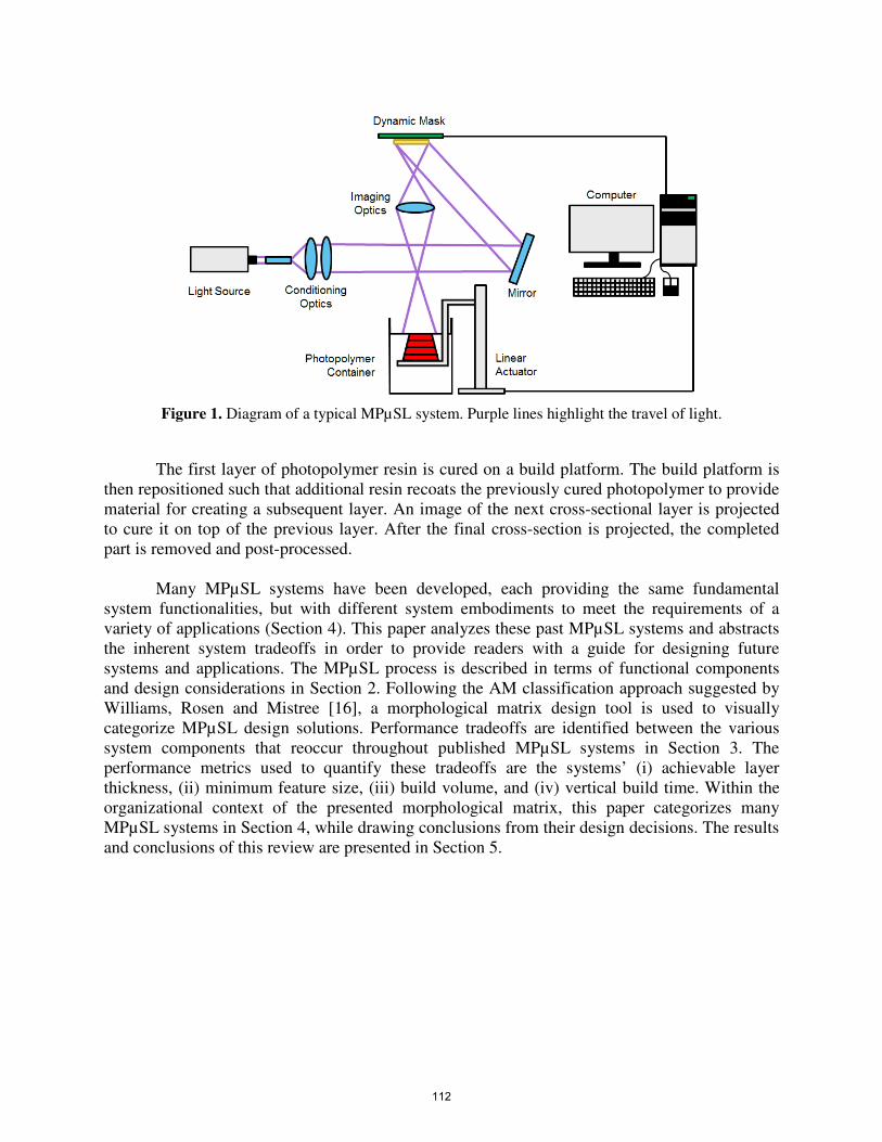
Figure 1. Diagram of a typical MPµSL system. Purple lines highlight the travel of light.
The first layer of photopolymer resin is cured on a build platform. The build platform is
then repositioned such that additional resin recoats the previously cured photopolymer to provide
material for creating a subsequent layer. An image of the next cross-sectional layer is projected
to cure it on top of the previous layer. After the final cross-section is projected, the completed
part is removed and post-processed.
Many MPµSL systems have been developed, each providing the same fundamental
system functionalities, but with different system embodiments to meet the requirements of a
variety of applications (Section 4). This paper analyzes these past MPµSL systems and abstracts
the inherent system tradeoffs in order to provide readers with a guide for designing future
systems and applications. The MPµSL process is described in terms of functional components
and design considerations in Section 2. Following the AM classification approach suggested by
Williams, Rosen and Mistree [16], a morphological matrix design tool is used to visually
categorize MPµSL design solutions. Performance tradeoffs are identified between the various
system components that reoccur throughout published MPµSL systems in Section 3. The
performance metrics used to quantify these tradeoffs are the systems’ (i) achievable layer
thickness, (ii) minimum feature size, (iii) build volume, and (iv) vertical build time. Within the
organizational context of the presented morphological matrix, this paper categorizes many
MPµSL systems in Section 4, while drawing conclusions from their design decisions. The results
and conclusions of this review are presented in Section 5.
112
2. MPµSL Functional Analysis This section describes the MPµSL process as a set of subfunctions and performance
parameters, which are shown through a functional decomposition and a morphological matrix.
2.1 MPµSL System Subfunctions The MPµSL process can be discretized into a set of functional subsystems, each with their
own set of unique design considerations. The final performance of a MPµSL system is dependent
on the sum of these functional parts. They are as follows:
• Light source produces the luminous energy that is projected onto the resin surface to selectively
cure photopolymer.
• Conditioning optics change properties of the projected light for MPµSL applications.
• Dynamic mask digitally patterns and projects incident light to selectively cure photopolymer.
• Projection orientation is the position of the dynamic mask relative to the polymer container.
• Imaging optics expand or reduce the projected image to achieve the desired image resolution.
• Recoat method supplies liquid photopolymer over previous layers for the creation of new layers.
• Build platform supports the object being made.
• Vertical actuator repositions the build platform for the creation of new layers.
• System controls programmatically alter system properties during the fabrication process.
• Photopolymer container holds the reservoir of photopolymer and contains the build platform.
• Photopolymer is the raw material used in MPµSL to fabricate three dimensional objects.
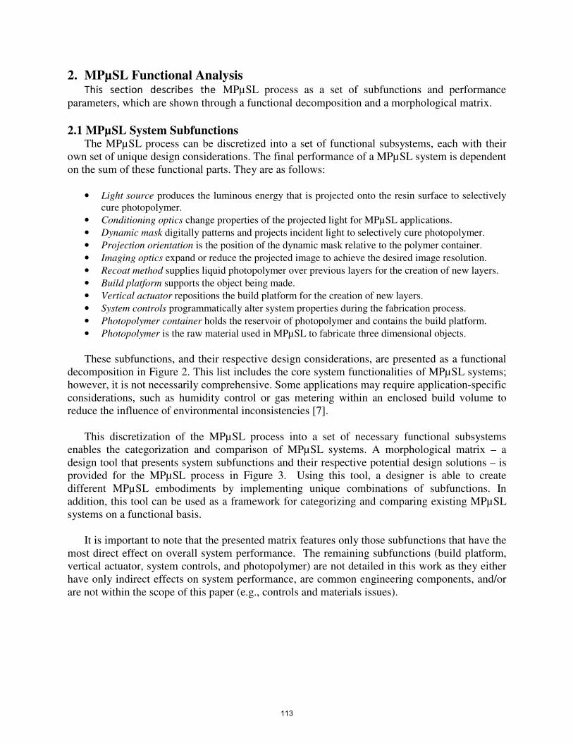
These subfunctions, and their respective design considerations, are presented as a functional
decomposition in Figure 2. This list includes the core system functionalities of MPµSL systems;
however, it is not necessarily comprehensive. Some applications may require application-specific
considerations, such as humidity control or gas metering within an enclosed build volume to
reduce the influence of environmental inconsistencies [7].
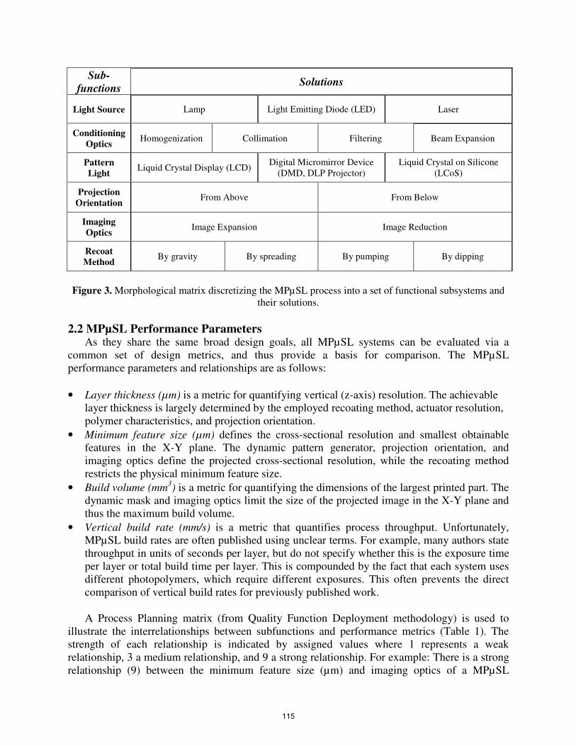
This discretization of the MPµSL process into a set of necessary functional subsystems
enables the categorization and comparison of MPµSL systems. A morphological matrix – a
design tool that presents system subfunctions and their respective potential design solutions – is
provided for the MPµSL process in Figure 3. Using this tool, a designer is able to create
different MPµSL embodiments by implementing unique combinations of subfunctions. In
addition, this tool can be used as a framework for categorizing and comparing existing MPµSL
systems on a functional basis.
It is important to note that the presented matrix features only those subfunctions that have the
most direct effect on overall system performance. The remaining subfunctions (build platform,
vertical actuator, system controls, and photopolymer) are not detailed in this work as they either
have only indirect effects on system performance, are common engineering components, and/or
are not within the scope of this paper (e.g., controls and materials issues).
113

Figure 2. Functional decomposition of the MPµSL process relating subfunctions to design considerations
114
Sub-
functions Solutions
Light Source Lamp Light Emitting Diode (LED) Laser
Conditioning
Optics Homogenization Collimation Filtering Beam Expansion
Pattern
Light Liquid Crystal Display (LCD)
Digital Micromirror Device
(DMD, DLP Projector)
Liquid Crystal on Silicone
(LCoS)
Projection
Orientation From Above From Below
Imaging
Optics Image Expansion Image Reduction
Recoat
Method By gravity By spreading By pumping By dipping
Figure 3. Morphological matrix discretizing the MPµSL process into a set of functional subsystems and
their solutions.
2.2 MPµSL Performance Parameters As they share the same broad design goals, all MPµSL systems can be evaluated via a
common set of design metrics, and thus provide a basis for comparison. The MPµSL
performance parameters and relationships are as follows:
• Layer thickness (µm) is a metric for quantifying vertical (z-axis) resolution. The achievable
layer thickness is largely determined by the employed recoating method, actuator resolution,
polymer characteristics, and projection orientation.
• Minimum feature size (µm) defines the cross-sectional resolution and smallest obtainable
features in the X-Y plane. The dynamic pattern generator, projection orientation, and
imaging optics define the projected cross-sectional resolution, while the recoating method
restricts the physical minimum feature size.
• Build volume (mm3) is a metric for quantifying the dimensions of the largest printed part. The
dynamic mask and imaging optics limit the size of the projected image in the X-Y plane and
thus the maximum build volume.
• Vertical build rate (mm/s) is a metric that quantifies process throughput. Unfortunately,
MPµSL build rates are often published using unclear terms. For example, many authors state
throughput in units of seconds per layer, but do not specify whether this is the exposure time
per layer or total build time per layer. This is compounded by the fact that each system uses
different photopolymers, which require different exposures. This often prevents the direct
comparison of vertical build rates for previously published work.
A Process Planning matrix (from Quality Function Deployment methodology) is used to
illustrate the interrelationships between subfunctions and performance metrics (Table 1). The
strength of each relationship is indicated by assigned values where 1 represents a weak
relationship, 3 a medium relationship, and 9 a strong relationship. For example: There is a strong
relationship (9) between the minimum feature size (µm) and imaging optics of a MPµSL
115
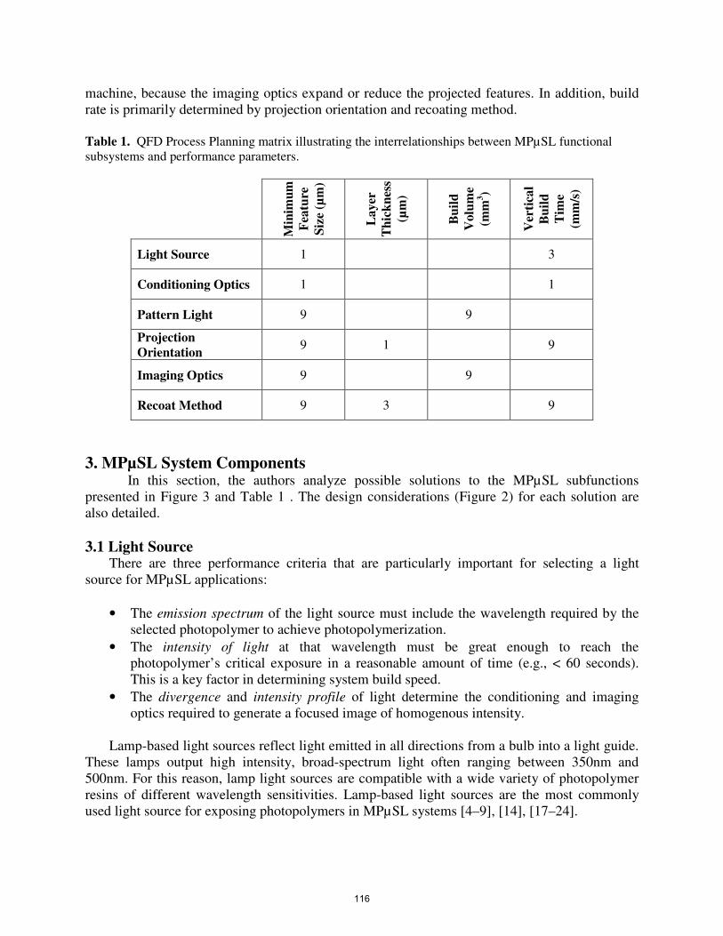
machine, because the imaging optics expand or reduce the projected features. In addition, build
rate is primarily determined by projection orientation and recoating method.
Table 1. QFD Process Planning matrix illustrating the interrelationships between MPµSL functional
subsystems and performance parameters.
Min
imu
m
Fea
ture
Siz
e (µ
m)
La
yer
Th
ick
nes
s
(µm
)
Bu
ild
Vo
lum
e
(mm
3)
Ver
tica
l
Bu
ild
Tim
e
(mm
/s)
Light Source 1 3
Conditioning Optics 1 1
Pattern Light 9 9
Projection
Orientation 9 1 9
Imaging Optics 9 9
Recoat Method 9 3 9
3. MPµSL System Components In this section, the authors analyze possible solutions to the MPµSL subfunctions
presented in Figure 3 and Table 1 . The design considerations (Figure 2) for each solution are
also detailed.
3.1 Light Source There are three performance criteria that are particularly important for selecting a light
source for MPµSL applications:
• The emission spectrum of the light source must include the wavelength required by the
selected photopolymer to achieve photopolymerization.
• The intensity of light at that wavelength must be great enough to reach the
photopolymer’s critical exposure in a reasonable amount of time (e.g., < 60 seconds).
This is a key factor in determining system build speed.
• The divergence and intensity profile of light determine the conditioning and imaging
optics required to generate a focused image of homogenous intensity.
Lamp-based light sources reflect light emitted in all directions from a bulb into a light guide.
These lamps output high intensity, broad-spectrum light often ranging between 350nm and
500nm. For this reason, lamp light sources are compatible with a wide variety of photopolymer
resins of different wavelength sensitivities. Lamp-based light sources are the most commonly
used light source for exposing photopolymers in MPµSL systems [4–9], [14], [17–24].
116

Light Emitting Diode (LED) sources are also used in MPµSL systems [3]. In general, LED
sources have longer operating lives, lower cost, smaller package size, and lower heat generation
than mercury lamps and lasers. LED sources generally output lower light intensities than lamps
at one or more wavelengths, which may be chosen to match the photopolymer’s polymerization
wavelength. LED sources are therefore more energy efficient than mercury lamps and lasers,
using energy more efficiently to photopolymerize the same volume of photopolymer [3].
Lasers have also been used in MPµSL systems [1], [2], [10–13]. Laser light sources may
emit light at a single wavelength or across multiple wavelengths. Lasers are available in
ultraviolet, visible, and infrared wavelengths, but often cost thousands of dollars more than the
other two light source options.
3.2 Conditioning Optics The system of optical components between the light source and dynamic mask generator is
referred to as the conditioning optics (Figure 1). These optical components change the properties
of the original light source before reaching the dynamic mask. Unfortunately, published MPµSL
systems underreport the specifics of these optical components, so it is difficult to discuss them in
great detail. However, commonly mentioned components include:
• Homogenizing rods that internally reflect light repeatedly to create even intensity
profiles. Light without a homogenous intensity profile fabricates inconsistent layer
thicknesses along the projected image. These inconsistencies will compound and create
dimensionally inaccurate parts [5], [24].
• Collimating lenses may be used to collimate a highly diverging source such as a lamp.
Well collimated light diverges very little, preventing unwanted beam divergence and the
resulting decrease in light density [4], [6–9], [17], [18], [23], [25].
• Filters may be used to remove unwanted wavelengths, isolating the desired wavelength
[4], [6–9], [17], [18], [23], [25].
• Beam expanding optics may be used to expand already collimated light from an LED,
laser, or collimating lenses [1], [2], [10–14].
Different light sources produce different levels of collimation and homogeneity. Lasers
produce the most collimated light with the most homogenous light intensity. Lamp light sources
often possess a Gaussian intensity distribution and non-collimated, widely diverging light. It is
the authors’ experience that LED light sources are often less collimated than lasers and possess
periodic drops in intensity distributions originating from their diodes.
Using the optical components listed above, the collimation and homogeneity of lamp and
LED light sources can be improved; however, it is difficult to achieve the same level of
performance as a laser.
3.3 Pattern Light A dynamic pattern generator digitally patterns and projects the conditioned light. Dynamic
masks all operate by discretizing light over a 2D array of pixels, each individually controlling the
light’s path. Important design considerations of the dynamic mask include its resolution, pixel
pitch, and transmission. Dynamic masks are used primarily in the digital display industry and
117

come in standard resolutions (e.g., 800x600, 1024x768, and 1920x1080). The pixel pitch
represents the size of each pixel and the space between pixels. Because optical magnification
must be uniform, the resolution and pixel pitch determines the ratio between the projected image
area and the minimum feature size. This limitation can only be overcome by moving the mask in
relation to the build platform, such that images are stitched together in the photopolymer [4].
Digital Micromirror Device (DMD), Liquid Crystal Display (LCD), and Liquid Crystal on
Silicon (LCoS) technologies have been used as dynamic masks throughout MPµSL.
3.3.1 Liquid Crystal Display (LCD)
Early MPµSL systems were implemented using LCD devices as the dynamic mask [1], [2],
[10–14]. LCD chips digitally pattern light by switching pixels between opaque and transparent
states, achieved by controlling the orientation of the liquid crystal molecules comprising the
pixel. However, the original LCD devices were not designed for use with UV light, and only
transmit about 12.5% of UV light [5].
3.3.2 Digital Micromirror Device (DMD)
Given LCD’s limited UV transmission, the DMD was used almost exclusively in MPµSL
systems after 1999 [4–10], [17–21], [23–26]. DMD’s discretize light over a 2D array of
aluminum micromirrors that are individually actuated between on and off orientations (+12
degrees) by electrostatic forces applied at their hinges. The DMD offers many advantages when
compared to other available dynamic masks:
• The DMD has small pixel sizes and narrow gaps between pixels. Because of this, DMDs
are designed with greater pixel density and can reflect incident light with a more uniform
intensity (less light is lost in the gaps). Therefore DMDs have a higher filling ratio
(reflective area/total area) compared to LCDs: 91% versus 57% [5].
• The modulation speed between states for individual pixels is also much less for DMDs as
compared with LCDs: 20µs versus 20ms. This allows for greater control of exposure time
and an increased ability to modulate individual pixels as to achieve gradient, grayscale
projection and digitally modulate the intensity of reflected light [5].
• The mirrors of the DMD are surfaced with aluminum that reflects approximately 88% of
the incident light, while LCDs typically transmit only 12.5% of incident light. DMDs are
therefore more efficient at patterning light and require less powerful light sources,
reducing system cost and complexity [5].
3.3.3 Liquid Crystal on Silicone (LCoS)
Liquid Crystal on Silicone (LCoS) devices are a reflective version of LCD technologies.
LCoS chips possess a 2D array of liquid crystals between one transparent thin-film transistor
(TFT) and one silicon semiconductor. The transparency of each pixel is controlled by the applied
voltage just as in LCD chips. Unlike LCD, the opaque pixels pass light to the underlying
reflective coating to project a pattern. Blocked light is reflected in a different direction. Unlike a
DMD, the reflective surface is static while the liquid crystals determine the reflection of light [3].
LCoS devices possess many of the same advantages over LCD devices as DMD devices.
LCoS devices generally have higher fill rates and smoother reflective surfaces than the DMD.
Unfortunately LCoS chips have poor contrast ratios and do not produce deep blacks. In
118
MPµSLA, projected images will have a base level of intensity even in areas that are meant to be
absent of light. This may unintentionally cure photopolymer and may even encourage the
development of artifacts or otherwise restrict dimensional accuracy within the cross section.
Furthermore, LCoS chips are difficult and expensive to manufacture making their availability
and cost to performance ratio less than that of DMDs [27].
3.4 Imaging Optics The optical components that modify the projected image are regarded as the imaging optics.
This series of lenses is typically designed with the intention of capturing the light projection
transmitting from the pattern generator and focusing it on the build surface. By choosing lenses
with specific focal lengths and numerical apertures, a desirable reduction ratio can be achieved.
The reduction ratio is what determines the achievable resolution and working area, but there
is a tradeoff between the two characteristics. A higher reduction ratio (lower magnification)
means that higher resolutions are achievable, but this reduces the overall projection area and
results in smaller part sizes. System magnification can be calculated using lens equations. For
example, Choi explains for a system with a magnification of 0.434, one pixel on the DMD (pitch
of 13.68 µm) would reduce to approximately 5.9 µm on the resin surface [17]. This constitutes
the physical limit of the X-Y resolution of a system, provided that the recoat method or print
orientation does not inhibit achievable feature sizes.
3.5 Recoat There are several methods for reapplying resin to the build surface. The methods include
recoating by gravity, by spreading, by pumping and by dipping (Figure 3).
Recoat by dipping is the most commonly used method for recoating in
microstereolithography. In this method, the build platform is dipped below the resin surface to
exactly one layer thickness depth. That layer is cured, and the stage descends into the vat of
photopolymer, which allows for fresh uncured resin to flow over the previously created layer.
The stage then returns to a location where the previously cured layer is exactly one layer
thickness below the resin surface [4–8], [17–20].
Recoat by gravity is used exclusively in bottom-up projection systems (explained further in
section 3.6). Unlike the dipping process when projecting from above, the build platform is raised
by the z-axis actuator to create a gap between the platform and the resin container for the next
layer. If the photopolymer has a low viscosity, it will flow into the created gap. If the
photopolymer has a high viscosity, the platform needs to be raised to an exaggerated height such
that the photopolymer can fill the gap. The z-axis actuator than moves the platform down until
the desired layer thickness gap is achieved, while extra photopolymer is forced to the sides [26].
Hypothetically, pumping the resin into the created gap could assist the recoat process when the
viscosity is too high.
Recoat by pumping is used rarely and does not refer specifically to a recoat practice. Systems
that utilize pumping in the recoat process typically are paired with a dipping process. One
instance of pumping identified in literature is a syringe pump that purges uncured resin from the
build surface with a high density “filler” material to prepare for the next layer [21]. In a multi-
119

material system developed by Choi, a “deep dip” process is imitated through precise and
extensive pumping [25].
Wiping or spreading uncured resin for recoating is a method common in stereolithography
practices [28], but is seldom used in microstereolithography. However, some MPµSL systems
utilize a squeegee or wiping system to recoat or level the resin surface [22].
3.6 Projection Orientation When deciding upon a base design for a microstereolithography system, besides the dynamic
mask, one of the most critical considerations is the orientation in which the system will be
projecting light on the build surface. Typically, there are two orientation options as shown in
Figure 4: a top-down approach where the path of light is projected from above onto the resin
surface (also referred to as “from above” projection orientation) and a bottom-up approach where
light is projected through the bottom surface of vat through a transparent window (also referred
to as “from below” projection orientation).
Figure 4. Illustration of different projection orientations: (a) image projection from above and (b) image
projection from below.
3.6.1 Projecting from above
Typically the slower and more common of the two possible system orientations, projecting
from above generally utilizes the dipping method to recoat the part. This approach demands that
a designer account for resin characteristics, such as surface tension, viscosity, and wetting, to
tune the process and achieve the desired layer thickness. In addition, these characteristics affect
polymer settling time, which along with actuator speed, directly influences the process
throughput.
In an effort to reduce recoat times, vibration assisted leveling has been experimented with to
encourage quicker leveling time of the photopolymer and to obtain thin layers [20], [29]. Also, as
mentioned in Section 3.5, Takahashi provides one instance in which a squeegee mechanism is
used for adjustment of the resin surface in MPµSL [22]. However, as high resolution is generally
in the scope of the top-down design, this type of recoat is avoided as sweeping motions may be
enough to agitate the resin or catch the part, destroying the print entirely.
120

3.6.2 Projecting from beneath
Projecting images through the bottom of the photopolymer container offers several
advantages over projecting images from above the container.
• Less photopolymer is required in the reservoir. Because the build part is not submerged
in photopolymer as when projecting from above, the reservoir container is independent of
part height and can be shallower. Less photopolymer can save time and/or reduce cost.
• System complexity decreases while the overall vertical print speed increases. When
projecting from below, gravity is used to more quickly move and settle the photopolymer.
Therefore it is unnecessary to implement recoating mechanisms like squeegees or long
waiting periods for photopolymer to settle.
• Thinner layers are theoretically possible. Achievable layer thickness in this orientation is
determined by the gap between the previously printed layer and the floor of the container,
which is directly limited and controlled by the resolution of the vertical actuator of the
build platform.
• Photopolymer can polymerize faster because it is removed from ambient oxygen that
would otherwise inhibit crosslinking.
As photopolymer cures between the floor of the resin container and the previous layer, it
adheres strongly to both. Forces upwards of 50N must be applied to overcome this adhesion and
move the build platform, destroying smaller features in the process [26]. Therefore, there is an
inherent tradeoff between printing speed and printing resolution for MPµSLA machines.
Researchers have developed a peeling process that is used when projecting underneath to
alleviate feature destruction caused by separation. In this process either the build tray or resin vat
is separated from the other by applying a gradual peeling force (like tape from a table). This
process reduces the separation force greatly, preserving features smaller than using the same
system without peeling. Unfortunately, the peeling process may prolong total build time and
negate the inherent speed advantage. Chen’s research group, however, has developed a fast mask
projection stereolithography process that bypasses this design tradeoff by applying a flexible
silicone membrane to the floor of the resin container [26]. This SYLGARD silicone gel
maintains a thin oxidation layer directly on its surface, inhibiting photopolymerization so that a
substantially smaller adhesion force is developed. The membrane is also flexible so that the
polymer container can slide easily under the build part, to another fresh section of photopolymer
(in the same container) for the next layer to cure. This process emulates a peeling step but with
much smaller displacements and applied forces, making the impact on overall print speed
negligible.
4. Categorization and Analysis of MPµSL Systems The morphological matrix introduced in Figure 3 provides a basis on which existing MPµSL
systems can be analyzed. The existing systems are presented in this section via a categorization
based on the critical architectural components of each system. Each morphological matrix is
accompanied by a corresponding table that specifies the systems’ respective performance
parameters. Together, this data provides a basis for determining the effect of system design
decisions on critical performance parameters.
121
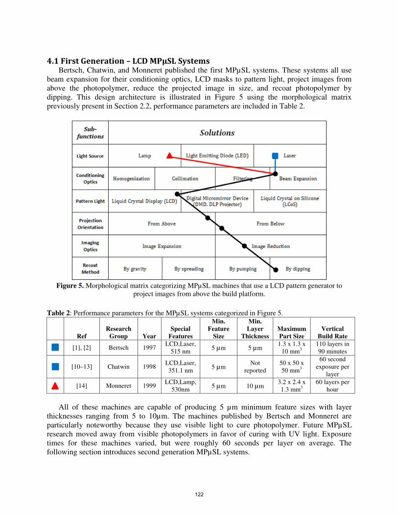
4.1 First Generation – LCD MPµSL Systems Bertsch, Chatwin, and Monneret published the first MPµSL systems. These systems all use
beam expansion for their conditioning optics, LCD masks to pattern light, project images from
above the photopolymer, reduce the projected image in size, and recoat photopolymer by
dipping. This design architecture is illustrated in Figure 5 using the morphological matrix
previously present in Section 2.2, performance parameters are included in Table 2.
Figure 5. Morphological matrix categorizing MPµSL machines that use a LCD pattern generator to
project images from above the build platform.
Table 2: Performance parameters for the MPµSL systems categorized in Figure 5.
Ref
Research
Group Year
Special
Features
Min.
Feature
Size
Min.
Layer
Thickness
Maximum
Part Size
Vertical
Build Rate
[1], [2] Bertsch 1997
LCD,Laser,
515 nm 5 µm 5 µm
1.3 x 1.3 x
10 mm3
110 layers in
90 minutes
[10–13] Chatwin 1998
LCD,Laser,
351.1 nm 5 µm
Not
reported
50 x 50 x
50 mm3
60 second
exposure per
layer
[14] Monneret 1999
LCD,Lamp,
530nm 5 µm 10 µm
3.2 x 2.4 x
1.3 mm3
60 layers per
hour
All of these machines are capable of producing 5 µm minimum feature sizes with layer
thicknesses ranging from 5 to 10µm. The machines published by Bertsch and Monneret are
particularly noteworthy because they use visible light to cure photopolymer. Future MPµSL
research moved away from visible photopolymers in favor of curing with UV light. Exposure
times for these machines varied, but were roughly 60 seconds per layer on average. The
following section introduces second generation MPµSL systems.
122

4.2 Second Generation – DMD MPµSL Systems The systems categorized in this section use a DMD to dynamically shape the projected
image. These systems were grouped together in order to identify the paradigm shift in design
decisions with the advent of the DMD. As outlined in Section 3.3.2, the transition from LCD to
DMD was a result of better performance characteristics such as smaller pixel sizes, narrower
gaps between pixels, higher modulation speeds, and high reflectivity. The morphological matrix
presented in Figure 6 represents systems that utilize a lamp, DMD dynamic mask, from-above
projection, image reducing optics, recoat by dipping, but employ unique conditioning optics.
Figure 6: Morphological matrix categorizing MPµSL machines that use a DMD pattern generator to
project images from above the build platform.
Table 3: Performance parameters for the MPµSL systems categorized in Figure 6.
Ref
Research
Group Year
Special
Feature
Min.
Feature
Size
Min.
Layer
Thickness Part Size
Vertical
Build Rate
[6] Rosen 2007 DMD, 365 nm 6 µm 400 µm 2 x 2 x 1
mm3
90s per layer
[7] Rosen 2007 DMD, 365,
435, 647 nm 5 µm 5 µm not reported 60s per layer
[17] Wicker 2009 DMD, 365 nm 30 µm 4 µm 1.95 x 1.95
x 2.4 mm3
<1s per layer
[4] Lee 2008 DMD, 365nm,
XY translation 2 µm 5 µm
10 x 10 x
2.68 mm3
100s per layer
[8], [9] Bertsch 1999 DMD, visible 5 µm 5 µm 6 x 8 x 15
mm3
700 layers in
2.5 hours
[18],
[23] Bertsch 2000 DMD, UV 10 µm 10 µm
10.24 x 7.68
x 20 mm3
200 layers in
1 hour
[5] Zhang 2005 DMD, 364 nm,
fly-eye lens 0.6 µm 5 µm not reported not reported
[19] Roy 2006 DMD, 355 nm 20 µm 150 µm not reported 90s per layer
[20] Hadipoespito 2003 DMD, 365 nm 20 µm 100 µm not reported not reported
123

As seen in Table 3, the reported achievable feature size of the DMD projection from above
systems utilizing the dipping recoat method ranges from 0.6 to 30 µm. While smaller feature
sizes were achieved with DMD based systems, the average achievable feature size is not
significantly smaller than LCD systems. Unfortunately, the vertical build rate metric for many of
these systems are not comparable as many publications use different speed metrics (as discussed
in Section 2.3). Regardless, all systems in Figure 5 and Figure 6 use the dipping recoat method,
and their build times seem comparable. However, as LCD masks transmit only 12.5% of UV
light (as mentioned in Section 3.3.1), build time can increase by a factor of 7 when compared to
systems using a DMD with the same light source.
Figure 7 and Table 4 presents systems using a DMD dynamic mask to project images from
above, while employing alternative solutions to achieve recoating.
Figure 7: Morphological matrix categorizing MPµSL machines that use alternative recoat methods.
Table 4: Performance parameters for the MPµSL systems categorized in Figure 7.
Ref
Research
Group Year Special Feature
Min.
Feature
Size
Min.
Layer
Thickness Part Size
Vertical Build
Rate
[25] Wicker 2009 DMD, 365 nm,
multi material ~50 µm 21 µm
~ 2 x 2 x 4
mm3
8-12s per layer
[22] Takahashi 2000 DMD, 365 nm 50 µm 200 µm ~ 2 x 2 x 2
mm3
not reported
[21] Roy 2008 DMD, 355 nm 50 µm 50 µm not reported 60s per layer
Comparing the systems’ performances listed in Tables 2 and 3 versus Table 4 (which
primarily differ by recoat method) suggests that systems that do not use recoat by dipping
generally have larger minimum feature sizes (approximately 50 µm) and layer thicknesses
ranging from 21 µm to 200 µm. This indicates that dipping may be the preferable method for
124
recoating if the goal of system is to achieve a minimum feature sizes (as discussed in Section
3.5).
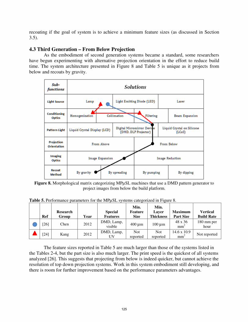
4.3 Third Generation – From Below Projection As the embodiment of second generation systems became a standard, some researchers
have begun experimenting with alternative projection orientation in the effort to reduce build
time. The system architecture presented in Figure 8 and Table 5 is unique as it projects from
below and recoats by gravity.
Figure 8. Morphological matrix categorizing MPµSL machines that use a DMD pattern generator to
project images from below the build platform.
Table 5. Performance parameters for the MPµSL systems categorized in Figure 8.
Ref
Research
Group Year
Special
Features
Min.
Feature
Size
Min.
Layer
Thickness
Maximum
Part Size
Vertical
Build Rate
[26] Chen 2012
DMD, Lamp,
visible 400 µm 100 µm
48 x 36
mm2
180 mm per
hour
[24] Kang 2012
DMD, Lamp,
UV
Not
reported
Not
reported
14.6 x 10.9
mm2
Not reported
The feature sizes reported in Table 5 are much larger than those of the systems listed in
the Tables 2-4, but the part size is also much larger. The print speed is the quickest of all systems
analyzed [26]. This suggests that projecting from below is indeed quicker, but cannot achieve the
resolution of top down projection systems. Work in this system embodiment still developing, and
there is room for further improvement based on the performance parameters advantages.
125
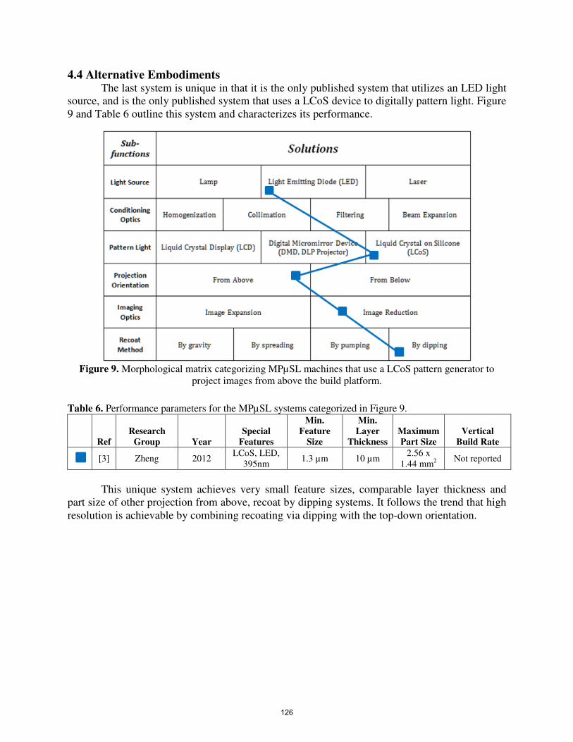
4.4 Alternative Embodiments The last system is unique in that it is the only published system that utilizes an LED light
source, and is the only published system that uses a LCoS device to digitally pattern light. Figure
9 and Table 6 outline this system and characterizes its performance.
Figure 9. Morphological matrix categorizing MPµSL machines that use a LCoS pattern generator to
project images from above the build platform.
Table 6. Performance parameters for the MPµSL systems categorized in Figure 9.
Ref
Research
Group Year
Special
Features
Min.
Feature
Size
Min.
Layer
Thickness
Maximum
Part Size
Vertical
Build Rate
[3] Zheng 2012
LCoS, LED,
395nm 1.3 µm 10 µm
2.56 x
1.44 mm2
Not reported
This unique system achieves very small feature sizes, comparable layer thickness and
part size of other projection from above, recoat by dipping systems. It follows the trend that high
resolution is achievable by combining recoating via dipping with the top-down orientation.
126

5. Closure This paper presents a MPµSL morphological matrix that is designed to functionally
categorize and compare the fundamental design decisions solved in the realization of MPµSL
systems. Using this matrix, several published MPµSL systems are analyzed in terms of critical
MPµSL performance parameters: minimum feature size (µm), layer thickness (µm), build
volume (mm3), and vertical build time (mm/s). These performance parameters are expressed in
units that serve as a standard benchmark to promote direct quantitative comparisons between
MPµSL systems. From this analysis, relationships between system performance and the
corresponding subsystems solutions have been identified to indicate general trends and tradeoffs.
• The most common system embodiments project images from above the photopolymer
container and dip the build platform to achieve recoating. These systems are capable of
achieving the smallest feature sizes, which are close to 1 µm.
• Dynamic mask selection does not significantly affect the minimum achievable feature
size. While pixel pitch is a relevant design consideration, final feature size is ultimately
determined by the imaging optics.
• Dynamic mask selection significantly affects the vertical build rate of a MPµSL system.
LCD masks transmit only 12.5% of UV light, which can increase build time by a factor
of 7 when compared to using a DMD with the same light source.
• The relationship between part size and feature size is equivalent to the relationship
between aspect ratio and pixel pitch for any dynamic mask. Future dynamic masks with
an equivalent pixel pitch but with greater resolution will enable creation of smaller
feature sizes on equally sized parts, or the same feature sizes on larger parts.
• If a fast vertical build rate is priority, then system embodiment should project images
from below the photopolymer vat. By using a gravity-assisted recoat approach, vertical
build rates can be improved by an order of magnitude.
• The type of light source is noncritical provided that emission properties (wavelength and
intensity) are suitable, and appropriate light conditioning is performed.
Amongst published MPµSL systems, design trends have changed historically. Exploration of
novel form factors and embodiments has been limited. An area for future research is in exploring
more unique embodiments and subsystem solutions. In doing so, the relationships between
MPµSL performance parameters and subsystem solutions can be more broadly and quantitatively
compared. Ultimately, such relationships could be used to develop processes more optimized for
desired performance as governed by the application.
6. Acknowledgements Earl Campaigne is supported by a research assistantship provided by a grant from the
Center for Innovative Technology. Philip Lambert is supported by a research assistantship
provided by Virginia Tech’s Institute for Critical Technology and Applied Science.
127

References
[1] A. Bertsch, S. Zissi, and J. Y. Je, “Microstereophotolithography using a liquid crystal
display as dynamic mask-generator,” 1997.
[2] A. Bertsch and J. C. Andr, “Study of the spatial resolution of a new 3D microfabrication
process : the microstereophotolithography using a dynamic mask-generator technique,”
vol. 107, pp. 275–281, 1997.
[3] X. Zheng, J. Deotte, M. P. Alonso, G. R. Farquar, T. H. Weisgraber, S. Gemberling, H.
Lee, N. Fang, and C. M. Spadaccini, “Design and optimization of a light-emitting diode
projection micro-stereolithography three-dimensional manufacturing system.,” The
Review of scientific instruments, vol. 83, no. 12, Dec. 2012.
[4] Y. M. Ha, J. W. Choi, and S. H. Lee, “Mass production of 3-D microstructures using
projection microstereolithography,” Journal of Mechanical Science and Technology, vol.
22, no. 3, pp. 514–521, May 2008.
[5] C. Sun, N. Fang, D. M. Wu, and X. Zhang, “Projection micro-stereolithography using
digital micro-mirror dynamic mask,” Sensors and Actuators A: Physical, vol. 121, no. 1,
pp. 113–120, May 2005.
[6] A. Limaye and D. D. W. Rosen, “Multi-Objective Process Planning Method For Mask
Projection Stereolithography,” Georgia Institute of Technology, 2007.
[7] B. M. Comeau, “Fabrication of Tissue Engineering Scaffolds Using Stereolithography,”
no. December, 2007.
[8] a. Bertsch, H. Lorenz, and P. Renaud, “3D microfabrication by combining
microstereolithography and thick resist UV lithography,” Sensors and Actuators A:
Physical, vol. 73, no. 1–2, pp. 14–23, Mar. 1999.
[9] A. Bertsch, L. Beluze, and P. Renaud, “Microstereolithography : a new process to build
complex 3D objects Fixed light spot,” vol. 3680, April, pp. 808–817, 1999.
[10] C. Chatwin, M. Farsari, S. Huang, P. Birch, F. Claret-Tournier, R. Young, D. Budgett, and
C. Bradfield, “Microfabrication by use of a spatial light modulator in the ultraviolet:
experimental results.,” Optics letters, vol. 24, no. 8, pp. 549–50, Apr. 1999.
[11] M. Farsari, F. Claret-Tournier, S. Huang, C. . Chatwin, D. . Budgett, P. . Birch, R. C. .
Young, and J. . Richardson, “A novel high-accuracy microstereolithography method
employing an adaptive electro-optic mask,” Journal of Materials Processing Technology,
vol. 107, no. 1–3, pp. 167–172, Nov. 2000.
[12] C. R. Chatwin, M. Farsari, S. Huang, M. I. Heywood, R. C. D. Young, P. M. Birch, F.
Claret-Tournier, and J. D. Richardson, “Characterisation of Epoxy Resins for
128
Microstereolithographic Rapid Prototyping,” The International Journal of Advanced
Manufacturing Technology, vol. 15, no. 4, pp. 281–286, Apr. 1999.
[13] C. Chatwin, M. Farsari, S. Huang, M. Heywood, P. Birch, R. Young, and J. Richardson,
“UV Microstereolithography System that uses Spatial Light Modulator Technology.,”
Applied optics, vol. 37, no. 32, pp. 7514–22, Nov. 1998.
[14] S. Monneret, V. Loubère, S. Corbel, D. De Chimie, and B. P. N. Cedex,
“Microstereolithography using a dynamic mask generator and a non-coherent visible light
source,” vol. 3680, no. April, pp. 553–561, 1999.
[15] A. Bertsch, “Microstereolithography: a Review,” in Materials Research Society
Symposium Proceedings, 2002, vol. 758, p. 15.
[16] C. B. Williams, F. Mistree, and D. W. Rosen, “A Functional Classification Framework for
the Conceptual Design of Additive Manufacturing Technologies,” Journal of Mechanical
Design, vol. 133, no. 12, p. 121002, 2011.
[17] J.-W. Choi, R. Wicker, S.-H. Lee, K.-H. Choi, C.-S. Ha, and I. Chung, “Fabrication of 3D
biocompatible/biodegradable micro-scaffolds using dynamic mask projection
microstereolithography,” Journal of Materials Processing Technology, vol. 209, no. 15–
16, pp. 5494–5503, Aug. 2009.
[18] A. Bertsch, P. Bernhard, C. Vogt, and P. Renaud, “Rapid prototyping of small size
objects,” Rapid Prototyping Journal, vol. 6, no. 4, pp. 259–266, 2000.
[19] Y. Lu, G. Mapili, G. Suhali, S. Chen, and K. Roy, “A digital micro-mirror device-based
system for the microfabrication of complex, spatially patterned tissue engineering
scaffolds.,” Journal of biomedical materials research. Part A, vol. 77, no. 2, pp. 396–405,
May 2006.
[20] G. W. Hadipoespito, Y. Yang, H. Choi, G. Ning, and X. Li, “Digital Micromirror Device
Based on Microstereolithography for Micro Structures of Transparent Photopolymer and
Nanocomposites,” University of Wisconsin-Madison, Madison, Wisconsin, 2003.
[21] L.-H. Han, G. Mapili, S. Chen, and K. Roy, “Projection Microfabrication of Three-
Dimensional Scaffolds for Tissue Engineering,” Journal Manufacturing Science and
Engineering, vol. Vol. 130, p. 021005: 1–4, 2008.
[22] K. Takahashi and J. Setoyama, “A UV‐exposure system using DMD,” Electronics and
Communications in Japan (Part II: Electronics), vol. 83, no. 7, pp. 56–58, Jul. 2000.
[23] A. Bertsch, P. Bernhard, and P. Renaud, “Microstereolithography : Concepts and
applications,” vol. 00, pp. 289–298, 2001.
129

[24] H.-W. Kang, J. H. Park, and D.-W. Cho, “A pixel based solidification model for
projection based stereolithography technology,” Sensors and Actuators A: Physical, vol.
178, pp. 223–229, May 2012.
[25] J.-W. Choi, E. MacDonald, and R. Wicker, “Multi-material microstereolithography,” The
International Journal of Advanced Manufacturing Technology, vol. 49, no. 5–8, pp. 543–
551, Dec. 2009.
[26] Y. Chen, Y. Pan, and C. Zhou, “A Fast Mask Projection Stereolithography Process for
Fabricating Digital Models in Minutes,” Journal of Manufacturing Science and
Engineering, vol. 134, no. 5, p. 051011, 2012.
[27] T. V. Wilson, “How LCoS Works.” [Online]. Available:
http://electronics.howstuffworks.com/lcos.htm. [Accessed: 08-Jul-2013].
[28] “3D Systems,” 2013. [Online]. Available: http://www.3dsystems.com/. [Accessed: 08-Jul-
2013].
[29] A. S. Limaye and D. W. Rosen, “Compensation zone approach to avoid print-through
errors in mask projection stereolithography builds,” Rapid Prototyping Journal, vol. 12,
no. 5, pp. 283–291, 2006.
130