design, construction and testing of the most … · changing the muffler can change the sound of a...
TRANSCRIPT

DESIGN, CONSTRUCTION AND TESTING
OF THE MOST EFFICIENT EXHAUST FOR
A MERCEDES-BENZ C-CLASS
By
Alex Kaplan
Agricultural Systems Management
BioResource and Agricultural Engineering Department
California Polytechnic State University
San Luis Obispo
2012

TITLE : Design of a Mercedes C Class Cat back Exhaust
AUTHOR : Alex Kaplan
DATE SUBMITTED : September 25, 2011
Richard A. Cavaletto
_________________________ _________________________
Senior Project Advisor Signature
_________________________
Date
Richard A. Cavaletto
_________________________ _________________________
Department Head Signature
_________________________
Date

ACKNOWLEDGEMENTS
I would like to thank Cal Poly’s BRAE department and all the professors that have
helped me learn valuable information that I was able to apply to this project and follow
something that I am truly passionate about. I’d like to thank my older brother Greg for
allowing me the space and tools to work on this project. I’d like to thank my parents for
helping my buy this car and supporting my work. I’d also like to thank HK automotive
for access to their dyno machine and allowing me to test and retest my car.
ABSTRACT
This senior project discusses the design factors associated with the construction of an
exhaust starting form the catalytic converters to the exhaust pipes in a Mercedes- Benz C-
Class. The exhaust systems will aim to gain an increase in performance and n\in overall
machine operational efficiency resulting in better gas mileage and more horsepower and
torque. This project goes into depth of the function of each exhaust and how it differs
from the previous system to the ending result, horsepower, miles per gallon, torque, and
how loud each system was at peak RPM’s. The system will meet all road legal
requirements and will operate safely and efficiently.

Disclaimer Statement
The university makes it clear that the information forwarded herewith is a project
resulting from a class assignment and has been graded and accepted only as a fulfillment
of a course requirement. Acceptance by the university does not imply technical accuracy
or reliability. Any use of the information in this report is made by the user(s) at his/her
own risk, which may include catastrophic failure of the device or infringement of patent
or copyright laws.
Therefore, the recipient and/or user of the information contained in this report agrees to
indemnify, defend and save harmless the Sate, its officers, agents, and employees from
any and all claims and losses accruing or resulting to any person, firm, or corporation
who may be injured or damaged as a result of the use of this report.

TABLE OF CONTENTS
SIGNATURE PAGE…………………………………………………..……………….ii
ACKNOWLEDGEMENTS……………………………………………………..........iii
ABSTRACT……………………………………..………………………………………iv
DISCLAIMER STATEMENT………………………………………………………...v
LIST OF FIGURES…………………………..………………………………………vii
LIST OF TABLES……………...…………………..……..…………………………viii
INTRODUCTION………………………………………………………………………1
LITERATURE REVIEW………………………………………………………………3
PROCEDURES AND METHODS…………………………………………………...7
RESULTS…………………………………………………………………………….
DISCUSSION…………………………………………………………………………
RECOMMENDATIONS……………………………………………………………..
REFERENCES………………………………………………………………………..
APPENDICES
Appendix A: How Project Meets Requirements for the ASM Major….
Appendix B: Calculations…………..……………………………………….

LIST OF FIGURES
Figure 1…………………………………………………..……………….10
Figure 2…………………………………………………..……………….12
Figure 3…………………………………………………..……………….13
Figure 4…………………………………………………..……………….14
Figure 5…………………………………………………..………………..15
Figure 6…………………………………………………..………………..15
Figure 7…………………………………………………..………………..16
Figure 8…………………………………………………..………………..16
Figure 9…………………………………………………..………………...16
Figure 10…………………………………………………..……………….17
Figure 11…………………………………………………..……………….18
Figure 12…………………………………………………..……………….18
Figure 13…………………………………………………..……………….18

LIST OF TABLES
Exhaust Tubing Size…………………………………………………..……………….13
Initial Test Results…………………………………………………..…...…………….16

INTRODUCTION
Background Information:
Currently there are no aftermarket complete exhaust systems for Mercedes C-class w-203
body styles produced from 2001-2007. The only products made are universal mufflers
that can fit on to the stock 2.5” piping. This project entails building and testing various
components of three major exhaust systems available for a 2001 Mercedes C240. The
project entails testing four major performance characteristics of an exhaust system: the
horsepower, torque, audio decibels, and miles per gallon. All three exhaust systems will
be designed using AutoCAD and then fabricated and tested to see which system yields
superior results. The three systems will include the stock exhaust system that currently is
on the car, an aftermarket exhaust system utilizing an aero muffler and a stock catalytic
converter, an x-pipe exhaust system utilizing two mufflers, a y-pipe system utilizing one
muffler, and the current stock exhaust. After the four tests are completed the results will
be analyzed to determine which system is superior.
Horsepower is defined as: a foot-pound-second unit of power, equivalent to 550 foot-
pounds per second, or 745.7 watts. My 2001 C240 currently dyno’s out to 168 rear wheel
horsepower. The car has no modifications to the engine exhaust or computer and only
modified in suspension and physical appearance. I hope to gain roughly 3-5 horsepower
increase with a cat back exhaust system.
Torque is defined as: Force multiplied by distance. Currently after being tested pn the
dyno the car produces 144 lb. /ft. of torque. The torque number is lower than the
horsepower due to the relatively weak 2.6 liter v6 engine that is small and meant as a
daily driver with little performance aspects. Larger eight cylinder engines produce more
torque than horsepower usually. Through the modification of the exhaust I hope to gain
5-10 lb. /ft. of torque
According to the CHP, “no exhaust shall not exceed 95 dB.” The car as it stand now
measures at 60 decibels due to it coming with two resonators which rates the car as
moderate in decibels. The exhaust in this particular vehicle reads higher or lower
depending on the gear due to the manual transmission giving higher rangers of Rotations
per Minute or RPM’s. The exhaust after modification will definitely be louder it must be
under 95 decibels which is easily attainable at max RPM’s which is 7000 RPMs.
With Gas prices raising at a rate of over 5% per year it is important to maximize miles
per gallon from existing cars. The Stock exhaust system that is currently on the car is

restrictive and with a freer flowing system gains in the males per gallon can easily be
achieved. Through research and testing I plan to determine which system will net the
largest increase of miles per gallon. I expect to gain at least 1-2 mpg increase with the
new system. I currently drive around ten thousand miles per year. The extra forty to fifty
miles I gain per tank could add up to saving over a thousand dollars a year on gas.
Having more efficient exhaust systems for all cars could be a cost efficient way to
maximize miles per gallon without having to do major engine modifications/
Figure 1: Test Car Mercedes-Benz C240

Literature Review
Exhausts are used in many internal combustion engines but this report will focus on the
uses for the automotive industry.
Exhaust Background
An exhaust system is usually tubing used to guide reaction exhaust gases away from a
controlled combustion inside an engine. The entire system takes the burnt gases away
from the engine and tends to include one or more exhaust pipes depending on the exhaust
system. It is important to carefully design an exhaust to carry poisonous gases away from
the engine. The gases from most engine types are extremely hot, and the exhaust piping
has to be heat-resistant. Also the exhaust system cannot be branched to or pass through
any part of the car that can damage be damaged by heat due to the pipes being extremely
hot while running.
Cat-back Exhaust Background
This project focuses on the design aspects of Cat-back exhausts because any modification
or removal of the Catalytic converter is not legal in the State of California. Cat-back
refers to the portion of the exhaust system from the outlet of the catalytic converter to the
final outlet of air, commonly seen as a tail pipe or muffler tip depending on the
application.
Modified cat-back exhaust systems tend to use a larger diameter exhaust pipe than the
stock system. To bend the exhaust piping to fit the application, a mandrel-bending
machine will be used to bend pipes to fit the automotive application. This allows the
exhaust gases to exit with as little back pressure as possible. The mufflers included in
these kits are containing fiberglass insulation to reduce back pressure and increase
controlled air flow. Depending on the system different mufflers will give off different
exhaust tunes, but this is a function of aesthetics and pleasing sound then any functioning
performance benefits.
Muffler Background
The mufflers on cars are installed along the exhaust pipe as part of the exhaust system of
an internal combustion engine. The muffler functions by reducing exhaust noise by the
absorption process. “The exhaust is routed through a series of passages and chambers
lined with roving fiberglass wool and resonating chambers tuned to cause destructive

interference wherein opposite sound waves cancel each other out, and Catalytic
converters also have a muffling effect.”
Changing the muffler can change the sound of a car's exhaust system considerably.
Removing a vehicle's muffler or installing a less effective muffler than the original can
cause the vehicle to violate noise regulations and performance aspects of a car.
Figure 2: Stock Muffler
In this particular application the Mercedes C240 has multiple muffling devices. It
contains two catalytic converters two separate resonators and one muffle at the end of the
exhaust system that all work together to dampen the noise of the engine. Most cars do not
contain two resonators or two catalytic converters but according to Mercedes-Benz
USA’s website “All Mercedes-Benz vehicles contain state of the art noise and vibration
dampening systems to make for the most comfortable and enjoyable ride possible.”
Y-Pipe System and X-Pipe System
The section of tubing between the catalytic converter and the rear muffler on cars that
have two parallel exhaust pipes can either take two shapes: the first being a Y-pipe
common in the majority of cars today, the second being an X-pipe was commonplace in
the muscle car era. Cars today are produced with smaller engines and the consumer
desires a quitter ride causing the automotive industry to go to the Y-pipe system.
Performance mid-pipes often have a perpendicular connecting pipe or the pipes
temporarily merge. This is to equalize the pressure in both exhaust pipes and keep the
engine back-pressure as low as possible since back-pressure is detrimental to high-end
power.

The Y-Style Pipe where there is a perpendicular connecting pipe, resembling the
letter Y. This is the exhaust mid-pipe section found in all cars produced today. It
provides moderate reduction in backpressure and good noise dampening
characteristics.
The X-Style Pipe is where the exhaust pipes temporarily merge, resembling the
letter X. This system is common in after-market exhausts especially in the off-
road community and in muscle-cars. This system requires running an additional
muffler after the mid-pipe “X”.
Importance of Backpressure
Back pressure refers to the resistance to a moving fluid by obstructions or tight bends in
the confinement vessel along which it is moving, such as piping or air vents, against its
direction of flow. Because it is really resistance, the term back pressure is misleading as
the pressure remains and causes flow in the same direction, but the flow is reduced due to
resistance. (Popular Mechanics 2009)
An automotive exhaust muffler with a particularly high number of twists, bends, turns
and right angles could be described as having particularly high back pressure back
pressure; this back pressure actually aids the performance in low end RPM settings such
as common city driving. Depending on the driving conditions of the automobile different
Figure 3: Y-Pipe Exhaust with 1st Resonator

exhaust backpressures can either positively or negatively affect horsepower, torque and
efficiency.
Exhaust Tubing Size
Magnaflow Mufflers provides a comprehensive guide for exhaust tubing size stating that
bigger exhaust tubing size doesn’t always guarantee more horsepower. The opposite may
be the case if the engine is too small to handle larger exhaust tubing size a loss of
backpressure will occur loosing horsepower and torque.(Magnaflow Mufflers 2010)
Figure 4: Engine Size and Horsepower in Relation to Exhaust Size

PROCEDURES AND METHODS
Design Procedure
The design constraints placed on this project came about through discussion with Dr.
Cavaletto, and Richard of RPM mufflers in Oceanside California, research from
automotive exhaust testing, muffler designs and placements, and laws and regulations in
regards to automotive exhausts.
To establish an accurate design procedure, testing of the current exhaust system was
necessary to determine the current baseline results of the car with the stock exhaust
system and muffler. All testing for this project was conducted HK motorsports, which is
located at 15020 Oxnard Street Unit A Van Nuys, California 91411. According to HK
Motorsports the staff has over 12 years of dyno tuning experience. HK is owned and
managed by Harry Khodanian a dedicated Automotive Enthusiast. Harry got his start as
an emissions testing and repair as Advance Emission Specialist where most work is
performed on modern day laboratory dynamometers and Harry carries all ASE
certifications.
The Dynomometer will test the horsepower and the torque of the car at peak RPM’s, but
it will not test the Decibels of the car at peak RPM or the miles per gallon. Testing the
miles per gallon is simple in the Mercedes because the computer screen in my car shows
the miles per gallon, speed driven, distance travelled, and the time the car has been
running. In order to test the decibels of the car a Scosche spl1000 SPL Meter was
purchased. This device will allow me to test up to a Db Range of 135 Db. This unit is
Figure 5: HK motorsports DynoJet
Dynomometer
Figure 6: Scosche
Dynomometer
affordable and effective.
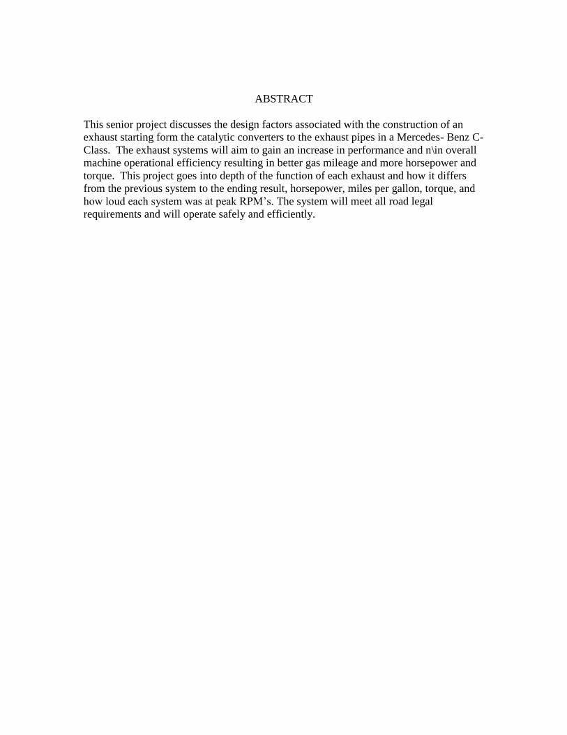
Initial Results:
Figure 7: Dynomometer Horsepower and Torque Maximums and Minimums
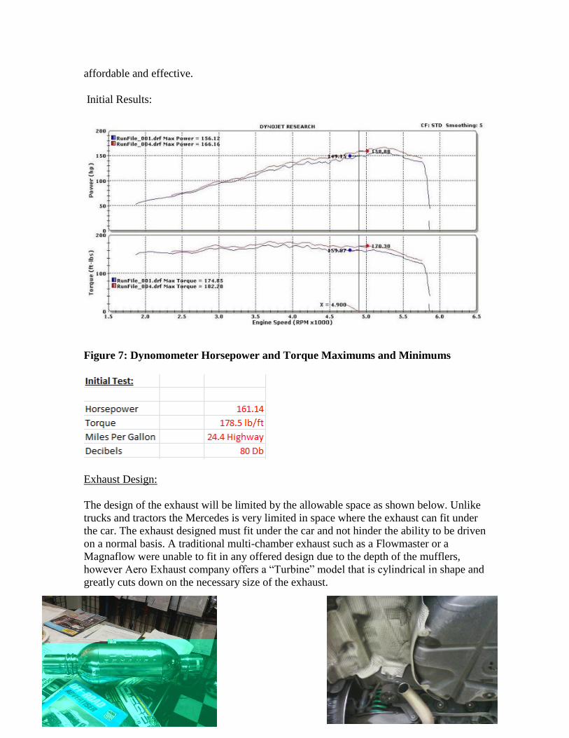
Exhaust Design:
The design of the exhaust will be limited by the allowable space as shown below. Unlike
trucks and tractors the Mercedes is very limited in space where the exhaust can fit under
the car. The exhaust designed must fit under the car and not hinder the ability to be driven
on a normal basis. A traditional multi-chamber exhaust such as a Flowmaster or a
Magnaflow were unable to fit in any offered design due to the depth of the mufflers,
however Aero Exhaust company offers a “Turbine” model that is cylindrical in shape and
greatly cuts down on the necessary size of the exhaust.

Welding Component of Project:
Exhaust can either be bolted into stock brackets if they are remanufactured; this project is
a one-off due to no Mercedes cat-back exhausts systems existing. Therefore this project
will require welding to secure all exhaust tubing and mufflers. All welding will be
performed by the student (Alex Kaplan) and the welder used for this project will be the
MIG welder made Miller by that utilizes 250 amps to weld. Welding the exhaust system
provides a stronger and longer lasting attachment to the automobile. Bolted systems can
loosen warp and deteriorate quicker or fail due to bolts shearing or failing. It is
imperative to make precise welds that are air tight to ensure that no exhaust fumes escape
in improper areas affecting performance or environmental aspects.
Welds around pipes need to be made in linear fashion not straying from ends of the
exhaust piping or muffler tips. The simplest and most effective way to test if welds have
been made properly is to flash a flash light through the pipes to see if any light escapes
the exhaust. A good weld will have no light rays escaping anywhere in the exhaust.
Multiple practice welds will be performed prior to exhaust building to ensure student is
competent in welding of the exhaust components.
Y-Pipe Exhaust Design:
The Y-pipe system will utilize the stock Y-pipe system that is currently on the car, but in
a modified version. The Y-shaped midpipe and the catalytic converters will remain in
place and stainless steel 2.5” piping will be welded into the Y-pipe leading into the
“Aero” muffler with a 6” exhaust tip welded to the muffler to make dampen noise, adhere
to California legal requirement, and make it easier to test the fabricated system. The
exhaust tip provides no performance advantage and serves mainly an aesthetic purpose.
For this project a low profile bevel tip will be used to remain flush with the rear bumper.

X-Pipe Exhaust Design:
The X-Pipe system varies from the Y-Pipe system because it is a dual exhaust system.
Two pipes run from the headers on a V style engine to a mid-pipe are beneficial to an
exhaust system versus running a true dual exhaust parallel straight off the headers
without an X or H pipe ( which is not legal in the State of California) and the X-Pipe
system can equalize back pressure from side to side and improve scaveging. The purpose
of this X-pipe system is to gain horsepower in the upper RPM’s of the motor (4000-7000
RPM) without losing any efficiency in gas mileage seen with the Y-Pipe system.
A basic drawing was created using AutoCad to layout a top-view of what the X-Pipe
system will look like on the car, the actual dimension may vary slightly due to the
restried amount of space that the undercarriage of the car contains. Space was not an
issue with the Y-Pipe system because it was using a modified stock exhaust in the same
location, the X-Pipe system will require modification of the rear bumper and removal of
some additional parts on the undercarriage. The undercarriage contains a skidplate-like
sheet of steel that is one quarter of an inch thick and painted black. The purpose of this
skid plate is to deflect any rocks or debris from hitting the driveshaft, brake lines or any
electrical components that could cause malfunction. This car contains this plate due to the
fact that it is extremely low to the ground. The car also contains a modified coil over
suspension which has lowered the car an additional 2.5” in the front and rear.

Fabrication of Project:
Fabrication of this project was a very involved part of the project. The fabrication process
began by determining what was necessary and what wasn’t as far as piping for building
exhausts. After the catalytic converter Mercedes includes two sets of resonators that
dampen vibration and reduce the exhausts sounds. Testing was necessary to determine
whether the removal of the resonators would still allow the car to pass the decibel portion
of the testing process. Each resonator was removed and then replaced by a section of 2.5”
stainless steel pipe of the same length that was welded into place. When the first
resonator was removed and the car was tested it produce 79 decibels. Next the second
resonator was removed from the stock exhaust system and the car tested at 99 decibels.
Once the second resonator was removed the car no longer passed the minimum
requirement for noise levels in the state of California.
Due to the noise requirements of the State of California each of the exhaust systems
fabricated in this senior project required the use of one resonator to muffle the sounds of
the exhaust enough to pass the decibel requirements. After the resonator portion of the
testing was completed the entire exhaust system after the headers was cut off using a
jigsaw. This was performed to test to see if the exhaust systems on automobiles actually
are beneficial to the cars from a performance aspect. The car was attached to a
dynamometer and tested, as well as tested in the miles per gallon test at 65 miles per hour
and using the decibel meter. The car lost horsepower and torque as well as was too loud
and lost fuel efficiency in the highway portion of the test. The operator of the nest noted

that the car accelerated much slower and the reduction of torque was apparent after the
dynamometer test.
The stock exhaust system utilizing two inch stainless steel pipes and a y-shaped midpipe
was reattached to the car using a weld around the entire pipe and then a baseline test was
performed. The next portion of the fabrication involved a modified y-pipe. The exhaust
was cut again using a jigsaw and ground to allow for a clean welding surface when the
modified y-pipe was attached again using a weld. 2.5” exhaust was used for this y-pipe to
determine whether a larger diameter exhaust pipe size would yield any performance
benefits. Once the length of 7.8 was determined as the necessary length of pipe 10 feet of
stainless steel was purchased from San Diego steel supply. A mandrel tube bender was
used to bend all of the piping and ensure that it fit with the contours of the undercarriage
of the car. As stated earlier the car is extremely cramped for space and bending of
exhaust pipe was required in order to allow proper fitment. The car has an independent
rear suspension even though it is rear wheel drive, which does allow for more space to
use when fabricating the exhaust. If the car had a solid rear axle whit the cramped of a
space, fabricating this project would have been impossible. Most trucks utilize a solid
rear axle due to heavy duty towing and hauling needs. This allows for a much greater
space of discretion to place exhaust pipes in a given manner.
Next began the process of fabricating the x-pipe system to the car, and the x-pipe system
was fabricated by removing the y-pipe exhaust system and also removing the skid plates
that were bolted on to the undercarriage. Removing the skid plate was difficult with a
ratchet and a socket so an air gun was used similar to the ones used by tire installation
shops. Once the skid plates were removed from the undercarriage of the car more space
was freed up to fabricate the exhaust. The x-pipe differs from the y-pipe system by using
a mid-pipe shaped in the form of the letter x that branches back out to a dual exhaust that
uses two resonators and two mufflers and has two exhaust tips space equally in the rear of
the car. The rear bumper of the car was also modified for this exhaust system requiring an
additional exhaust hole cut to fit the additional pipe.
Results:

Testing of Y-Pipe:
Testing of the Y-Pipe has yet to be completed.
Testing of X-Pipe:
The X-Pipe system yielded a loss of horsepower and torque after testing on the
dynamometer. This is likely due to the fact that the amount of exhaust pipes are
excessively large for the
Exhaust that will be used on Automobile:
After completing the testing of the exhausts all evidence points to the modified y-pipe as
the superior exhaust system for this particular automobile. The y-pipe proved superior in
every facet of the testing process. The y-pipe produced more horsepower, torque, and
miles per gallon at the 2.5” pipe diameter size. The y-pipe also tested in at 80 decibels
and remained legal in the State of California.
The X-pipe system did not perform as well as expected, in theory the additional pipes
should have provided and increase in horsepower and torque, but there actually was a
slight decrease in both. The loss of mileage was negligible at best. The x-pipe system was
significantly louder and drew unwanted attention to the car from police officers and was
to loud as stated by the State of California. The loss in horsepower was due to the engine
not being able to produce enough backpressure from the exhaust system. This is a result
of having excessive exhaust pipes or having a pipe that is too large in diameter. It would
be interesting to see that if using a smaller diameter pipe on the x-pipe system would not
lose horsepower.
It is difficult to set a benchmark for exhaust sizing and design, if a car has a larger engine
and especially an eight cylinder engine, the design can be more flexible and different
exhaust system will gain different horsepower increases. In general an exhaust will gain
efficiencies based on the engine size and pipe diameter in the table stated above. To use
these exhaust system the vehicle must have a v style engine and not an inline cylinder
placement in small four cylinder engines, dodge six cylinder diesel’s, and with tractors.
These engines will have a single set of cylinders and will only be able to run exhaust
systems with a single pipe. The v-displacement engine common in six and eight cylinder
engines allows more flexibility in the exhaust design.
Analysis of Results:
Issues:
One of the main issues encountered while completing this project were finding space to
fabricate the X-pipe system. The Y-pipe system fit with no clearance issues whatsoever,
but fabricating the X-pipe requires some modifications of the cars undercarriage. For this
project two large skid plates on the undercarriage were removed in order to allow for

access to more space to fabricate the exhaust system. Having access to a mandrel tube
bender mad the fabrication of the x-pipe system run more smoothly. This allowed for
precise bends to the exhaust piping. If a pipe did not fit under the car in a certain manner
the tube bender allowed for precise bends to fit better.
Another issue that occurred was unwanted attention from police officers in San Luis
Obispo. While testing numerous citations were given out for modified exhaust systems,
this occurred while testing the car with no exhaust system, no resonators, and with the x-
pipe system. Once the car had the final y-pipe assembly no issues occurred with police
officers and the exhaust is legal in the state of California and recently passed a smog test
on the first try.
Recommendations:
The type of exhaust system to install for a given vehicle depends on the application. If a
farm or agricultural operation utilizes large trucks with 8 cylinder engines for towing,
hauling, or any other heavy duty operations then utilizing an x-pipe exhaust on the truck
may be beneficial giving it additional horsepower and torque. If a company uses lots of
light duty four and six cylinder vehicles in their fleet the Y-pipe system
Feasibility of Project:
This is a very feasible project for anyone interested in gaining efficiencies in their motor
vehicles. The fabrication component is not extremely difficult and if a welder is readily
available and someone has welding experience it can be completed in a weekend if it is
worked on until completed. Calculations to determine the ideal exhaust tubing size ratio
to engine size is necessary first. Access to a mandrel tube bender is key this reduces the
working time dramatically and allows for precise bends of exhaust tubing, which was
extremely important for this project because space was so limited in this application.
When fabricating exhausts on a larger vehicle precise bends are not as necessary because
an excess of space is available under the cab allowing for a straighter flowing exhaust
system.
After completing this project it is a highly feasible project that more companies should
look into. If a company has a large fleet of truck and work vehicles, the company could
see improvements in gas mileage and other capabilities. This project could be completed
for under two hundred and fifty dollars per vehicle and the truck will make it back easily
within the first year. If a truck drives an average of 15000 miles per year and average 15
miles per gallon, if a new exhaust is fabricated and it gets 17 miles per gallon with a
modified exhaust it averages thirteen percent more miles per gallon and would save 120
gallons of fuel a year and with the rising fuel costs of over 4 dollars per gallon that could
save a company with a fleet of trucks over four hundred and eighty dollars a year. The
amount of savings will increase with the rise in gads prices. The longer the company
keeps the truck the more economy a company receives can be seen.