design criteria active - scroundtree.com
TRANSCRIPT


Design Criteria RoundTree SC Association Soilder Pile Retaining Wall Date: 4/10/2019
ACTIVE
SEISMIC sf
HEIGHTS 18 16 15 14 12
Pa (lbs/FT2) 1141.791 1014.925 951.493 888.060 761.194
Active Pressure 85 lbs/ft3 Ptotal 13770.000 10880.000 9562.500 8330.000 6120.000
SPACING 6 ft pa1 (force) kips 20.552239 18.268657 17.126866 12.4328358 10.656716
pa2 (force) kips 41.104478 32.477612 28.544776 24.8656716 18.268657
pa3 (force) kips 20.346716 14.066866 11.303731 12.3085075 7.5358209
Patotal 82.003433 64.813134 56.975373 49.6070149 36.461194
PASSIVE 400 lbs/ft3
pa1 (location) ft 11.000 9.000 8.000 8.556 6.556
pa2 (location) ft 9.000 7.333 6.500 7.000 5.333
pa3 (location) ft 7.000 5.444 4.667 5.444 3.889
PA1(MOMENT) kips*ft 226.075 164.418 137.015 106.370 69.861
PA2(MOMENT) 369.940 238.169 185.541 174.060 97.433
PA3(MOMENT) 142.427 76.586 52.751 67.013 29.306
`
moment arm 10.8 9.6 9 8.4 7.2
Peq (kips) 34.992 27.648 24.300 21.168 15.552
Peq (moment) 79.362 0.000 0.000 0.000 0.000
Tie back reaction (T) lbs 90.867 68.453 62.551 49.635 39.320
Reaction Force (R ) lbs 26.128 24.008 18.724 21.140 12.693
H1 LOCATION 9 9 9 7 7
Percentage seismic to tieback 0.21 0 0 0 0
h5 11.426362 11.055615 11.680051 13.106706 8.8215483
Retaining Wall Calculations with Tiebacks
��� = 18�
��� = ��
2
�� =���
0.67�

h1= 9 ft Heights 9 8 6 4 2
ϒ= 85 lbs/ft3 Steel I beam
SPACING= 6 ft Active Pressure(Kips) 20.655 16.32 9.18 4.08 1.02
Semsic Load(kips) 8.748 6.912 3.888 1.728 0.432
f1= 20.655 kips
f2= 8.748 kips Wood Lagging
Active Pressure (ksf) 0.765 0.68 0.51 0.34 0.17
f1+f2= 29.403 kips Sesmic Load (ksf) 0.162 0.144 0.108 0.072 0.036
h1= 3 ft
h2= 5.4 ft Force for Embedment (Kips) 29.403 23.232 9.18 4.08 1.02
No Seismic Force for walls 6' or less
h4= 3.71405 ft
Embedment Calculations Retaining Wall Calculations without tiebacks

Pole Footing Embedded in Soil ENERCALC, INC. 1983-2015, Build:6.15.1.19, Ver:6.15.1.19
Licensee : HOGAN LAND SERVICES INC.Lic. # : KW-06001541
File = S:\!MASTER PROJECT LIST\3874 RoundTree SC -Palo Verde Terrace\CIVIL\3874 - retaining wall calculations.ec6
Description : Embedment 18
Code References
Calculations per IBC 2012 1807.3, CBC 2013, ASCE 7-10
Load Combinations Used : IBC 2012
General InformationCircular
23'-6
"11'-5
-1/1
6"
Footing Diameter = 2'-0"
Soil Surface No lateral restraint
Point Load24.0
300.02,000.0
No Lateral Restraint at Ground Surface
Pole Footing ShapeFooting Diameter . . . . . . . . . . . . . . in
Allow Passive . . . . . . . . . . . . . . . . . . . . . . pcf
Max Passive . . . . . . . . . . . . . . . . . . . . . . psf
Calculate Min. Depth for Allowable Pressures
+D+HGoverning Load Combination :
Lateral Load 26.128Moment 298.382 k-ft
Minimum Required Depth 23.50 ft
k
NO Ground Surface Restraint
Pressures at 1/3 Depth
Actual 2,000.0 psf
Allowable 2,000.0 psf
Controlling Values
ft^2Footing Base Area 3.142
Maximum Soil Pressure 0.0 ksf
k
k
k
k
k
Applied Loads
k
Lateral Concentrated Load
D : Dead Load
L : Live
Lr : Roof Live
S : Snow
W : Wind
E : Earthquake
H : Lateral Earth
Load distance above
26.128
11.420
k
k
k
k
k
k
k
ft
Lateral Distributed Load
TOP of Load above ground surface
BOTTOM of Load above ground surface
k/ft
k/ft
k/ft
k/ft
k/ft
k/ft
k/ft
ftground surface
ft
Vertical Load
k
Load Combination Results
Factor
Soil IncreaseForces @ Ground Surface
Load Combination
Required
Loads - (k) Moments - (ft-k) Depth - (ft)
Pressure at 1/3 Depth
Allow - (psf)
Actual - (psf)
2,000.0 26.128 298.382+D+H 23.50 1.000 2,000.0
2,000.0 26.128 298.382+D+L+H 23.50 1.000 2,000.0
2,000.0 26.128 298.382+D+Lr+H 23.50 1.000 2,000.0
2,000.0 26.128 298.382+D+S+H 23.50 1.000 2,000.0
2,000.0 26.128 298.382+D+0.750Lr+0.750L+H 23.50 1.000 2,000.0
2,000.0 26.128 298.382+D+0.750L+0.750S+H 23.50 1.000 2,000.0
2,000.0 26.128 298.382+D+0.60W+H 23.50 1.000 2,000.0
2,000.0 26.128 298.382+D+0.70E+H 23.50 1.000 2,000.0
2,000.0 26.128 298.382+D+0.750Lr+0.750L+0.450W+H 23.50 1.000 2,000.0

Pole Footing Embedded in Soil ENERCALC, INC. 1983-2015, Build:6.15.1.19, Ver:6.15.1.19
Licensee : HOGAN LAND SERVICES INC.Lic. # : KW-06001541
File = S:\!MASTER PROJECT LIST\3874 RoundTree SC -Palo Verde Terrace\CIVIL\3874 - retaining wall calculations.ec6
Description : Embedment 18
2,000.0 26.128 298.382+D+0.750L+0.750S+0.450W+H 23.50 1.000 2,000.0
2,000.0 26.128 298.382+D+0.750L+0.750S+0.5250E+H 23.50 1.000 2,000.0
1,767.9 15.677 179.029+0.60D+0.60W+0.60H 17.75 1.000 1,768.0
1,767.9 15.677 179.029+0.60D+0.70E+0.60H 17.75 1.000 1,768.0

Pole Footing Embedded in Soil ENERCALC, INC. 1983-2015, Build:6.15.1.19, Ver:6.15.1.19
Licensee : HOGAN LAND SERVICES INC.Lic. # : KW-06001541
File = S:\!MASTER PROJECT LIST\3874 RoundTree SC -Palo Verde Terrace\CIVIL\3874 - retaining wall calculations.ec6
Description : Embedment 16
Code References
Calculations per IBC 2012 1807.3, CBC 2013, ASCE 7-10
Load Combinations Used : IBC 2012
General InformationCircular
21'-1
0-1
/2"
11'-0
-5/8
Footing Diameter = 2'-0"
Soil Surface No lateral restraint
Point Load24.0
300.02,000.0
No Lateral Restraint at Ground Surface
Pole Footing ShapeFooting Diameter . . . . . . . . . . . . . . in
Allow Passive . . . . . . . . . . . . . . . . . . . . . . pcf
Max Passive . . . . . . . . . . . . . . . . . . . . . . psf
Calculate Min. Depth for Allowable Pressures
+D+HGoverning Load Combination :
Lateral Load 24.008Moment 265.288 k-ft
Minimum Required Depth 21.875 ft
k
NO Ground Surface Restraint
Pressures at 1/3 Depth
Actual 1,998.76 psf
Allowable 2,000.0 psf
Controlling Values
ft^2Footing Base Area 3.142
Maximum Soil Pressure 0.0 ksf
k
k
k
k
k
Applied Loads
k
Lateral Concentrated Load
D : Dead Load
L : Live
Lr : Roof Live
S : Snow
W : Wind
E : Earthquake
H : Lateral Earth
Load distance above
24.008
11.050
k
k
k
k
k
k
k
ft
Lateral Distributed Load
TOP of Load above ground surface
BOTTOM of Load above ground surface
k/ft
k/ft
k/ft
k/ft
k/ft
k/ft
k/ft
ftground surface
ft
Vertical Load
k
Load Combination Results
Factor
Soil IncreaseForces @ Ground Surface
Load Combination
Required
Loads - (k) Moments - (ft-k) Depth - (ft)
Pressure at 1/3 Depth
Allow - (psf)
Actual - (psf)
1,998.8 24.008 265.288+D+H 21.88 1.000 2,000.0
1,998.8 24.008 265.288+D+L+H 21.88 1.000 2,000.0
1,998.8 24.008 265.288+D+Lr+H 21.88 1.000 2,000.0
1,998.8 24.008 265.288+D+S+H 21.88 1.000 2,000.0
1,998.8 24.008 265.288+D+0.750Lr+0.750L+H 21.88 1.000 2,000.0
1,998.8 24.008 265.288+D+0.750L+0.750S+H 21.88 1.000 2,000.0
1,998.8 24.008 265.288+D+0.60W+H 21.88 1.000 2,000.0
1,998.8 24.008 265.288+D+0.70E+H 21.88 1.000 2,000.0
1,998.8 24.008 265.288+D+0.750Lr+0.750L+0.450W+H 21.88 1.000 2,000.0

Pole Footing Embedded in Soil ENERCALC, INC. 1983-2015, Build:6.15.1.19, Ver:6.15.1.19
Licensee : HOGAN LAND SERVICES INC.Lic. # : KW-06001541
File = S:\!MASTER PROJECT LIST\3874 RoundTree SC -Palo Verde Terrace\CIVIL\3874 - retaining wall calculations.ec6
Description : Embedment 16
1,998.8 24.008 265.288+D+0.750L+0.750S+0.450W+H 21.88 1.000 2,000.0
1,998.8 24.008 265.288+D+0.750L+0.750S+0.5250E+H 21.88 1.000 2,000.0
1,697.2 14.405 159.173+0.60D+0.60W+0.60H 17.00 1.000 1,697.6
1,697.2 14.405 159.173+0.60D+0.70E+0.60H 17.00 1.000 1,697.6

Pole Footing Embedded in Soil ENERCALC, INC. 1983-2015, Build:6.15.1.19, Ver:6.15.1.19
Licensee : HOGAN LAND SERVICES INC.Lic. # : KW-06001541
File = S:\!MASTER PROJECT LIST\3874 RoundTree SC -Palo Verde Terrace\CIVIL\3874 - retaining wall calculations.ec6
Description : Embedment 14
Code References
Calculations per IBC 2012 1807.3, CBC 2013, ASCE 7-10
Load Combinations Used : IBC 2012
General InformationCircular
20'-1
0-1
/2"
13'-1
-3/1
6"
Footing Diameter = 2'-0"
Soil Surface No lateral restraint
Point Load24.0
300.02,000.0
No Lateral Restraint at Ground Surface
Pole Footing ShapeFooting Diameter . . . . . . . . . . . . . . in
Allow Passive . . . . . . . . . . . . . . . . . . . . . . pcf
Max Passive . . . . . . . . . . . . . . . . . . . . . . psf
Calculate Min. Depth for Allowable Pressures
+D+HGoverning Load Combination :
Lateral Load 21.168Moment 277.301 k-ft
Minimum Required Depth 20.875 ft
k
NO Ground Surface Restraint
Pressures at 1/3 Depth
Actual 1,998.65 psf
Allowable 2,000.0 psf
Controlling Values
ft^2Footing Base Area 3.142
Maximum Soil Pressure 0.0 ksf
k
k
k
k
k
Applied Loads
k
Lateral Concentrated Load
D : Dead Load
L : Live
Lr : Roof Live
S : Snow
W : Wind
E : Earthquake
H : Lateral Earth
Load distance above
21.168
13.10
k
k
k
k
k
k
k
ft
Lateral Distributed Load
TOP of Load above ground surface
BOTTOM of Load above ground surface
k/ft
k/ft
k/ft
k/ft
k/ft
k/ft
k/ft
ftground surface
ft
Vertical Load
k
Load Combination Results
Factor
Soil IncreaseForces @ Ground Surface
Load Combination
Required
Loads - (k) Moments - (ft-k) Depth - (ft)
Pressure at 1/3 Depth
Allow - (psf)
Actual - (psf)
1,998.7 21.168 277.301+D+H 20.88 1.000 2,000.0
1,998.7 21.168 277.301+D+L+H 20.88 1.000 2,000.0
1,998.7 21.168 277.301+D+Lr+H 20.88 1.000 2,000.0
1,998.7 21.168 277.301+D+S+H 20.88 1.000 2,000.0
1,998.7 21.168 277.301+D+0.750Lr+0.750L+H 20.88 1.000 2,000.0
1,998.7 21.168 277.301+D+0.750L+0.750S+H 20.88 1.000 2,000.0
1,998.7 21.168 277.301+D+0.60W+H 20.88 1.000 2,000.0
1,998.7 21.168 277.301+D+0.70E+H 20.88 1.000 2,000.0
1,998.7 21.168 277.301+D+0.750Lr+0.750L+0.450W+H 20.88 1.000 2,000.0

Pole Footing Embedded in Soil ENERCALC, INC. 1983-2015, Build:6.15.1.19, Ver:6.15.1.19
Licensee : HOGAN LAND SERVICES INC.Lic. # : KW-06001541
File = S:\!MASTER PROJECT LIST\3874 RoundTree SC -Palo Verde Terrace\CIVIL\3874 - retaining wall calculations.ec6
Description : Embedment 14
1,998.7 21.168 277.301+D+0.750L+0.750S+0.450W+H 20.88 1.000 2,000.0
1,998.7 21.168 277.301+D+0.750L+0.750S+0.5250E+H 20.88 1.000 2,000.0
1,661.8 12.701 166.380+0.60D+0.60W+0.60H 16.63 1.000 1,662.3
1,661.8 12.701 166.380+0.60D+0.70E+0.60H 16.63 1.000 1,662.3

Pole Footing Embedded in Soil ENERCALC, INC. 1983-2015, Build:6.15.1.19, Ver:6.15.1.19
Licensee : HOGAN LAND SERVICES INC.Lic. # : KW-06001541
File = S:\!MASTER PROJECT LIST\3874 RoundTree SC -Palo Verde Terrace\CIVIL\3874 - retaining wall calculations.ec6
Description : Embedment 12
Code References
Calculations per IBC 2012 1807.3, CBC 2013, ASCE 7-10
Load Combinations Used : IBC 2012
General InformationCircular
15'-7
-1/2
"8'-9
-5/8
Footing Diameter = 2'-0"
Soil Surface No lateral restraint
Point Load24.0
300.02,000.0
No Lateral Restraint at Ground Surface
Pole Footing ShapeFooting Diameter . . . . . . . . . . . . . . in
Allow Passive . . . . . . . . . . . . . . . . . . . . . . pcf
Max Passive . . . . . . . . . . . . . . . . . . . . . . psf
Calculate Min. Depth for Allowable Pressures
+D+HGoverning Load Combination :
Lateral Load 12.693Moment 111.698 k-ft
Minimum Required Depth 15.625 ft
k
NO Ground Surface Restraint
Pressures at 1/3 Depth
Actual 1,549.77 psf
Allowable 1,550.92 psf
Controlling Values
ft^2Footing Base Area 3.142
Maximum Soil Pressure 0.0 ksf
k
k
k
k
k
Applied Loads
k
Lateral Concentrated Load
D : Dead Load
L : Live
Lr : Roof Live
S : Snow
W : Wind
E : Earthquake
H : Lateral Earth
Load distance above
12.693
8.80
k
k
k
k
k
k
k
ft
Lateral Distributed Load
TOP of Load above ground surface
BOTTOM of Load above ground surface
k/ft
k/ft
k/ft
k/ft
k/ft
k/ft
k/ft
ftground surface
ft
Vertical Load
k
Load Combination Results
Factor
Soil IncreaseForces @ Ground Surface
Load Combination
Required
Loads - (k) Moments - (ft-k) Depth - (ft)
Pressure at 1/3 Depth
Allow - (psf)
Actual - (psf)
1,549.8 12.693 111.698+D+H 15.63 1.000 1,550.9
1,549.8 12.693 111.698+D+L+H 15.63 1.000 1,550.9
1,549.8 12.693 111.698+D+Lr+H 15.63 1.000 1,550.9
1,549.8 12.693 111.698+D+S+H 15.63 1.000 1,550.9
1,549.8 12.693 111.698+D+0.750Lr+0.750L+H 15.63 1.000 1,550.9
1,549.8 12.693 111.698+D+0.750L+0.750S+H 15.63 1.000 1,550.9
1,549.8 12.693 111.698+D+0.60W+H 15.63 1.000 1,550.9
1,549.8 12.693 111.698+D+0.70E+H 15.63 1.000 1,550.9
1,549.8 12.693 111.698+D+0.750Lr+0.750L+0.450W+H 15.63 1.000 1,550.9

Pole Footing Embedded in Soil ENERCALC, INC. 1983-2015, Build:6.15.1.19, Ver:6.15.1.19
Licensee : HOGAN LAND SERVICES INC.Lic. # : KW-06001541
File = S:\!MASTER PROJECT LIST\3874 RoundTree SC -Palo Verde Terrace\CIVIL\3874 - retaining wall calculations.ec6
Description : Embedment 12
1,549.8 12.693 111.698+D+0.750L+0.750S+0.450W+H 15.63 1.000 1,550.9
1,549.8 12.693 111.698+D+0.750L+0.750S+0.5250E+H 15.63 1.000 1,550.9
1,253.2 7.616 67.019+0.60D+0.60W+0.60H 12.63 1.000 1,254.6
1,253.2 7.616 67.019+0.60D+0.70E+0.60H 12.63 1.000 1,254.6

Pole Footing Embedded in Soil ENERCALC, INC. 1983-2015, Build:6.15.1.19, Ver:6.15.1.19
Licensee : HOGAN LAND SERVICES INC.Lic. # : KW-06001541
File = S:\!MASTER PROJECT LIST\3874 RoundTree SC -Palo Verde Terrace\CIVIL\3874 - retaining wall calculations.ec6
Description : Embedment 9
Code References
Calculations per IBC 2012 1807.3, CBC 2013, ASCE 7-10
Load Combinations Used : IBC 2012
General InformationCircular
20'-7
-1/2
"3'-8
-1/2
"
Footing Diameter = 2'-0"
Soil Surface No lateral restraint
Point Load24.0
300.02,000.0
No Lateral Restraint at Ground Surface
Pole Footing ShapeFooting Diameter . . . . . . . . . . . . . . in
Allow Passive . . . . . . . . . . . . . . . . . . . . . . pcf
Max Passive . . . . . . . . . . . . . . . . . . . . . . psf
Calculate Min. Depth for Allowable Pressures
+D+HGoverning Load Combination :
Lateral Load 29.403Moment 109.085 k-ft
Minimum Required Depth 20.625 ft
k
NO Ground Surface Restraint
Pressures at 1/3 Depth
Actual 1,998.87 psf
Allowable 2,000.0 psf
Controlling Values
ft^2Footing Base Area 3.142
Maximum Soil Pressure 0.0 ksf
k
k
k
0.0
k
0.0
0.0
0.0
k
Applied Loads
k
0.0
Lateral Concentrated Load
D : Dead Load
L : Live
Lr : Roof Live
S : Snow
W : Wind
E : Earthquake
H : Lateral Earth
Load distance above
0.0
0.0
0.0
0.0
0.0
0.0
29.403
3.710
k
k
k
k
k
k
k
ft
Lateral Distributed Load
TOP of Load above ground surface
BOTTOM of Load above ground surface
0.0
0.0
0.0
0.0
0.0
0.0
0.0
0.0
0.0
k/ft
k/ft
k/ft
k/ft
k/ft
k/ft
k/ft
ftground surface
ft
Vertical Load
k0.0
0.0
Load Combination Results
Factor
Soil IncreaseForces @ Ground Surface
Load Combination
Required
Loads - (k) Moments - (ft-k) Depth - (ft)
Pressure at 1/3 Depth
Allow - (psf)
Actual - (psf)
1,998.9 29.403 109.085+D+H 20.63 1.000 2,000.0
1,998.9 29.403 109.085+D+L+H 20.63 1.000 2,000.0
1,998.9 29.403 109.085+D+Lr+H 20.63 1.000 2,000.0
1,998.9 29.403 109.085+D+S+H 20.63 1.000 2,000.0
1,998.9 29.403 109.085+D+0.750Lr+0.750L+H 20.63 1.000 2,000.0
1,998.9 29.403 109.085+D+0.750L+0.750S+H 20.63 1.000 2,000.0
1,998.9 29.403 109.085+D+0.60W+H 20.63 1.000 2,000.0
1,998.9 29.403 109.085+D+0.70E+H 20.63 1.000 2,000.0
1,998.9 29.403 109.085+D+0.750Lr+0.750L+0.450W+H 20.63 1.000 2,000.0

Pole Footing Embedded in Soil ENERCALC, INC. 1983-2015, Build:6.15.1.19, Ver:6.15.1.19
Licensee : HOGAN LAND SERVICES INC.Lic. # : KW-06001541
File = S:\!MASTER PROJECT LIST\3874 RoundTree SC -Palo Verde Terrace\CIVIL\3874 - retaining wall calculations.ec6
Description : Embedment 9
1,998.9 29.403 109.085+D+0.750L+0.750S+0.450W+H 20.63 1.000 2,000.0
1,998.9 29.403 109.085+D+0.750L+0.750S+0.5250E+H 20.63 1.000 2,000.0
1,606.8 17.642 65.451+0.60D+0.60W+0.60H 16.13 1.000 1,607.7
1,606.8 17.642 65.451+0.60D+0.70E+0.60H 16.13 1.000 1,607.7

Pole Footing Embedded in Soil ENERCALC, INC. 1983-2015, Build:6.15.1.19, Ver:6.15.1.19
Licensee : HOGAN LAND SERVICES INC.Lic. # : KW-06001541
File = S:\!MASTER PROJECT LIST\3874 RoundTree SC -Palo Verde Terrace\CIVIL\3874 - retaining wall calculations.ec6
Description : Embedment 8
Code References
Calculations per IBC 2012 1807.3, CBC 2013, ASCE 7-10
Load Combinations Used : IBC 2012
General InformationCircular
18'-1
-1/2
"3'-3
-5/8
Footing Diameter = 2'-0"
Soil Surface No lateral restraint
Point Load24.0
300.02,000.0
No Lateral Restraint at Ground Surface
Pole Footing ShapeFooting Diameter . . . . . . . . . . . . . . in
Allow Passive . . . . . . . . . . . . . . . . . . . . . . pcf
Max Passive . . . . . . . . . . . . . . . . . . . . . . psf
Calculate Min. Depth for Allowable Pressures
+D+HGoverning Load Combination :
Lateral Load 23.232Moment 76.666 k-ft
Minimum Required Depth 18.125 ft
k
NO Ground Surface Restraint
Pressures at 1/3 Depth
Actual 1,804.97 psf
Allowable 1,805.88 psf
Controlling Values
ft^2Footing Base Area 3.142
Maximum Soil Pressure 0.0 ksf
k
k
k
k
k
Applied Loads
k
Lateral Concentrated Load
D : Dead Load
L : Live
Lr : Roof Live
S : Snow
W : Wind
E : Earthquake
H : Lateral Earth
Load distance above
23.232
3.30
k
k
k
k
k
k
k
ft
Lateral Distributed Load
TOP of Load above ground surface
BOTTOM of Load above ground surface
k/ft
k/ft
k/ft
k/ft
k/ft
k/ft
k/ft
ftground surface
ft
Vertical Load
k
Load Combination Results
Factor
Soil IncreaseForces @ Ground Surface
Load Combination
Required
Loads - (k) Moments - (ft-k) Depth - (ft)
Pressure at 1/3 Depth
Allow - (psf)
Actual - (psf)
1,805.0 23.232 76.666+D+H 18.13 1.000 1,805.9
1,805.0 23.232 76.666+D+L+H 18.13 1.000 1,805.9
1,805.0 23.232 76.666+D+Lr+H 18.13 1.000 1,805.9
1,805.0 23.232 76.666+D+S+H 18.13 1.000 1,805.9
1,805.0 23.232 76.666+D+0.750Lr+0.750L+H 18.13 1.000 1,805.9
1,805.0 23.232 76.666+D+0.750L+0.750S+H 18.13 1.000 1,805.9
1,805.0 23.232 76.666+D+0.60W+H 18.13 1.000 1,805.9
1,805.0 23.232 76.666+D+0.70E+H 18.13 1.000 1,805.9
1,805.0 23.232 76.666+D+0.750Lr+0.750L+0.450W+H 18.13 1.000 1,805.9

Pole Footing Embedded in Soil ENERCALC, INC. 1983-2015, Build:6.15.1.19, Ver:6.15.1.19
Licensee : HOGAN LAND SERVICES INC.Lic. # : KW-06001541
File = S:\!MASTER PROJECT LIST\3874 RoundTree SC -Palo Verde Terrace\CIVIL\3874 - retaining wall calculations.ec6
Description : Embedment 8
1,805.0 23.232 76.666+D+0.750L+0.750S+0.450W+H 18.13 1.000 1,805.9
1,805.0 23.232 76.666+D+0.750L+0.750S+0.5250E+H 18.13 1.000 1,805.9
1,428.1 13.939 45.999+0.60D+0.60W+0.60H 14.38 1.000 1,429.4
1,428.1 13.939 45.999+0.60D+0.70E+0.60H 14.38 1.000 1,429.4

Pole Footing Embedded in Soil ENERCALC, INC. 1983-2015, Build:6.15.1.19, Ver:6.15.1.19
Licensee : HOGAN LAND SERVICES INC.Lic. # : KW-06001541
File = S:\!MASTER PROJECT LIST\3874 RoundTree SC -Palo Verde Terrace\CIVIL\3874 - retaining wall calculations.ec6
Description : Embedment 6
Code References
Calculations per IBC 2012 1807.3, CBC 2013, ASCE 7-10
Load Combinations Used : IBC 2012
General InformationCircular
11
'-4-1
/2"
2'-0
"
Footing Diameter = 2'-0"
Soil Surface No lateral restraint
Point Load24.0
300.02,000.0
No Lateral Restraint at Ground Surface
Pole Footing ShapeFooting Diameter . . . . . . . . . . . . . . in
Allow Passive . . . . . . . . . . . . . . . . . . . . . . pcf
Max Passive . . . . . . . . . . . . . . . . . . . . . . psf
Calculate Min. Depth for Allowable Pressures
+D+HGoverning Load Combination :
Lateral Load 9.180Moment 18.360 k-ft
Minimum Required Depth 11.375 ft
k
NO Ground Surface Restraint
Pressures at 1/3 Depth
Actual 1,131.13 psf
Allowable 1,132.35 psf
Controlling Values
ft^2Footing Base Area 3.142
Maximum Soil Pressure 0.0 ksf
k
k
k
k
k
Applied Loads
k
Lateral Concentrated Load
D : Dead Load
L : Live
Lr : Roof Live
S : Snow
W : Wind
E : Earthquake
H : Lateral Earth
Load distance above
9.180
2.0
k
k
k
k
k
k
k
ft
Lateral Distributed Load
TOP of Load above ground surface
BOTTOM of Load above ground surface
k/ft
k/ft
k/ft
k/ft
k/ft
k/ft
k/ft
ftground surface
ft
Vertical Load
k
Load Combination Results
Factor
Soil IncreaseForces @ Ground Surface
Load Combination
Required
Loads - (k) Moments - (ft-k) Depth - (ft)
Pressure at 1/3 Depth
Allow - (psf)
Actual - (psf)
1,131.1 9.180 18.360+D+H 11.38 1.000 1,132.3
1,131.1 9.180 18.360+D+L+H 11.38 1.000 1,132.3
1,131.1 9.180 18.360+D+Lr+H 11.38 1.000 1,132.3
1,131.1 9.180 18.360+D+S+H 11.38 1.000 1,132.3
1,131.1 9.180 18.360+D+0.750Lr+0.750L+H 11.38 1.000 1,132.3
1,131.1 9.180 18.360+D+0.750L+0.750S+H 11.38 1.000 1,132.3
1,131.1 9.180 18.360+D+0.60W+H 11.38 1.000 1,132.3
1,131.1 9.180 18.360+D+0.70E+H 11.38 1.000 1,132.3
1,131.1 9.180 18.360+D+0.750Lr+0.750L+0.450W+H 11.38 1.000 1,132.3

Pole Footing Embedded in Soil ENERCALC, INC. 1983-2015, Build:6.15.1.19, Ver:6.15.1.19
Licensee : HOGAN LAND SERVICES INC.Lic. # : KW-06001541
File = S:\!MASTER PROJECT LIST\3874 RoundTree SC -Palo Verde Terrace\CIVIL\3874 - retaining wall calculations.ec6
Description : Embedment 6
1,131.1 9.180 18.360+D+0.750L+0.750S+0.450W+H 11.38 1.000 1,132.3
1,131.1 9.180 18.360+D+0.750L+0.750S+0.5250E+H 11.38 1.000 1,132.3
895.2 5.508 11.016+0.60D+0.60W+0.60H 9.00 1.000 895.2
895.2 5.508 11.016+0.60D+0.70E+0.60H 9.00 1.000 895.2

Pole Footing Embedded in Soil ENERCALC, INC. 1983-2015, Build:6.15.1.19, Ver:6.15.1.19
Licensee : HOGAN LAND SERVICES INC.Lic. # : KW-06001541
File = S:\!MASTER PROJECT LIST\3874 RoundTree SC -Palo Verde Terrace\CIVIL\3874 - retaining wall calculations.ec6
Description : Embedment 4
Code References
Calculations per IBC 2012 1807.3, CBC 2013, ASCE 7-10
Load Combinations Used : IBC 2012
General InformationCircular
7'-7
-1/2
"1
'-3-1
5/1
6"
Footing Diameter = 2'-0"
Soil Surface No lateral restraint
Point Load
24.0
300.02,000.0
No Lateral Restraint at Ground Surface
Pole Footing ShapeFooting Diameter . . . . . . . . . . . . . . in
Allow Passive . . . . . . . . . . . . . . . . . . . . . . pcf
Max Passive . . . . . . . . . . . . . . . . . . . . . . psf
Calculate Min. Depth for Allowable Pressures
+D+HGoverning Load Combination :
Lateral Load 4.080Moment 5.426 k-ft
Minimum Required Depth 7.625 ft
k
NO Ground Surface Restraint
Pressures at 1/3 Depth
Actual 753.56 psf
Allowable 755.09 psf
Controlling Values
ft^2Footing Base Area 3.142
Maximum Soil Pressure 0.0 ksf
k
k
k
k
k
Applied Loads
k
Lateral Concentrated Load
D : Dead Load
L : Live
Lr : Roof Live
S : Snow
W : Wind
E : Earthquake
H : Lateral Earth
Load distance above
4.080
1.330
k
k
k
k
k
k
k
ft
Lateral Distributed Load
TOP of Load above ground surface
BOTTOM of Load above ground surface
k/ft
k/ft
k/ft
k/ft
k/ft
k/ft
k/ft
ftground surface
ft
Vertical Load
k
Load Combination Results
Factor
Soil IncreaseForces @ Ground Surface
Load Combination
Required
Loads - (k) Moments - (ft-k) Depth - (ft)
Pressure at 1/3 Depth
Allow - (psf)
Actual - (psf)
753.6 4.080 5.426+D+H 7.63 1.000 755.1
753.6 4.080 5.426+D+L+H 7.63 1.000 755.1
753.6 4.080 5.426+D+Lr+H 7.63 1.000 755.1
753.6 4.080 5.426+D+S+H 7.63 1.000 755.1
753.6 4.080 5.426+D+0.750Lr+0.750L+H 7.63 1.000 755.1
753.6 4.080 5.426+D+0.750L+0.750S+H 7.63 1.000 755.1
753.6 4.080 5.426+D+0.60W+H 7.63 1.000 755.1
753.6 4.080 5.426+D+0.70E+H 7.63 1.000 755.1
753.6 4.080 5.426+D+0.750Lr+0.750L+0.450W+H 7.63 1.000 755.1

Pole Footing Embedded in Soil ENERCALC, INC. 1983-2015, Build:6.15.1.19, Ver:6.15.1.19
Licensee : HOGAN LAND SERVICES INC.Lic. # : KW-06001541
File = S:\!MASTER PROJECT LIST\3874 RoundTree SC -Palo Verde Terrace\CIVIL\3874 - retaining wall calculations.ec6
Description : Embedment 4
753.6 4.080 5.426+D+0.750L+0.750S+0.450W+H 7.63 1.000 755.1
753.6 4.080 5.426+D+0.750L+0.750S+0.5250E+H 7.63 1.000 755.1
596.4 2.448 3.256+0.60D+0.60W+0.60H 6.00 1.000 596.9
596.4 2.448 3.256+0.60D+0.70E+0.60H 6.00 1.000 596.9

Steel Beam ENERCALC, INC. 1983-2015, Build:6.15.1.19, Ver:6.15.1.19Licensee : HOGAN LAND SERVICES INC.Lic. # : KW-06001541
File = S:\!MASTER PROJECT LIST\3874 RoundTree SC -Palo Verde Terrace\CIVIL\3874 - retaining wall calculations.ec6
Description : Beam 18.0 with 9' Tiebacks
CODE REFERENCESCalculations per AISC 360-10, IBC 2012, ASCE 7-10Load Combination Set : ASCE 7-10Material Properties
Analysis Method :ksi
Bending Axis : Major Axis BendingLoad Combination :ASCE 7-10
Beam is Fully Braced against lateral-torsional bucklingAllowable Strength Design Fy : Steel Yield : 50.0 ksi
Beam Bracing : E: Modulus : 29,000.0
Span = 18.0 ft
W12x152
H(20.55) H(34.99) H(41.1) H(20.34) H(-90)
.Service loads entered. Load Factors will be applied for calculations.Applied LoadsBeam self weight NOT internally calculated and addedLoad(s) for Span Number 1
Point Load : H = 20.550 k @ 11.0 ft, (ACTIVE)Point Load : H = 34.990 k @ 10.80 ft, (SEISMIC)Point Load : H = 41.10 k @ 9.0 ft, (ACTIVE)Point Load : H = 20.340 k @ 7.0 ft, (ACTIVE)Point Load : H = -90.0 k @ 9.0 ft, (TIEBACK)
.Design OKDESIGN SUMMARYMaximum Bending Stress Ratio = 0.505 : 1
Load Combination +D+H
Span # where maximum occurs Span # 1Location of maximum on span 0.000ft
55.540 kMn / Omega : Allowable 606.287 k-ft Vn/Omega : Allowable
W12x152Section used for this span
Span # where maximum occursLocation of maximum on span
Span # 1
Load Combination +D+H238.380 k
Section used for this span W12x152Ma : Applied
Maximum Shear Stress Ratio = 0.233 : 1
9.090 ft
306.222 k-ft Va : Applied
0 <360411
Ratio = 0 <180
Maximum DeflectionMax Downward Transient Deflection 1.051 in 411Ratio =Max Upward Transient Deflection 0.000 in Ratio =Max Downward Total Deflection 1.051 in Ratio =Max Upward Total Deflection 0.000 in
.Maximum Forces & Stresses for Load Combinations
Span #Summary of Moment ValuesLoad Combination Summary of Shear ValuesMax Stress Ratios
M V Mmax -Mmax + Rm VnxMa - Max Mnx/Omega Cb Va MaxMnx Vnx/OmegaSegment Length+D+H Dsgn. L = 18.00 ft 1 0.505 0.233 -306.22 306.22 1,012.50 606.29 1.00 1.00 55.54 357.57 238.38+D+L+H Dsgn. L = 18.00 ft 1 0.505 0.233 -306.22 306.22 1,012.50 606.29 1.00 1.00 55.54 357.57 238.38+D+Lr+H Dsgn. L = 18.00 ft 1 0.505 0.233 -306.22 306.22 1,012.50 606.29 1.00 1.00 55.54 357.57 238.38+D+S+H Dsgn. L = 18.00 ft 1 0.505 0.233 -306.22 306.22 1,012.50 606.29 1.00 1.00 55.54 357.57 238.38+D+0.750Lr+0.750L+H Dsgn. L = 18.00 ft 1 0.505 0.233 -306.22 306.22 1,012.50 606.29 1.00 1.00 55.54 357.57 238.38+D+0.750L+0.750S+H Dsgn. L = 18.00 ft 1 0.505 0.233 -306.22 306.22 1,012.50 606.29 1.00 1.00 55.54 357.57 238.38+D+0.60W+H Dsgn. L = 18.00 ft 1 0.505 0.233 -306.22 306.22 1,012.50 606.29 1.00 1.00 55.54 357.57 238.38+D+0.70E+H Dsgn. L = 18.00 ft 1 0.505 0.233 -306.22 306.22 1,012.50 606.29 1.00 1.00 55.54 357.57 238.38+D+0.750Lr+0.750L+0.450W+H Dsgn. L = 18.00 ft 1 0.505 0.233 -306.22 306.22 1,012.50 606.29 1.00 1.00 55.54 357.57 238.38+D+0.750L+0.750S+0.450W+H

Steel Beam ENERCALC, INC. 1983-2015, Build:6.15.1.19, Ver:6.15.1.19Licensee : HOGAN LAND SERVICES INC.Lic. # : KW-06001541
File = S:\!MASTER PROJECT LIST\3874 RoundTree SC -Palo Verde Terrace\CIVIL\3874 - retaining wall calculations.ec6
Description : Beam 18.0 with 9' Tiebacks
Span #Summary of Moment ValuesLoad Combination Summary of Shear ValuesMax Stress Ratios
M V Mmax -Mmax + Rm VnxMa - Max Mnx/Omega Cb Va MaxMnx Vnx/OmegaSegment Length Dsgn. L = 18.00 ft 1 0.505 0.233 -306.22 306.22 1,012.50 606.29 1.00 1.00 55.54 357.57 238.38+D+0.750L+0.750S+0.5250E+H Dsgn. L = 18.00 ft 1 0.505 0.233 -306.22 306.22 1,012.50 606.29 1.00 1.00 55.54 357.57 238.38+0.60D+0.60W+0.60H Dsgn. L = 18.00 ft 1 0.303 0.140 -183.73 183.73 1,012.50 606.29 1.00 1.00 33.32 357.57 238.38+0.60D+0.70E+0.60H Dsgn. L = 18.00 ft 1 0.303 0.140 -183.73 183.73 1,012.50 606.29 1.00 1.00 33.32 357.57 238.38
.Location in SpanLoad CombinationMax. "-" Defl Location in SpanLoad Combination Span Max. "+" Defl
Overall Maximum Deflections
H Only 1 1.0511 18.000 0.0000 0.000.
Load Combination Support 1 Support 2Vertical Reactions Support notation : Far left is #1 Values in KIPS
Overall MAXimum 26.980Overall MINimum 16.188+D+H 26.980+D+L+H 26.980+D+Lr+H 26.980+D+S+H 26.980+D+0.750Lr+0.750L+H 26.980+D+0.750L+0.750S+H 26.980+D+0.60W+H 26.980+D+0.70E+H 26.980+D+0.750Lr+0.750L+0.450W+H 26.980+D+0.750L+0.750S+0.450W+H 26.980+D+0.750L+0.750S+0.5250E+H 26.980+0.60D+0.60W+0.60H 16.188+0.60D+0.70E+0.60H 16.188D OnlyLr OnlyL OnlyS OnlyW OnlyE OnlyH Only 26.980

Steel Beam ENERCALC, INC. 1983-2015, Build:6.15.1.19, Ver:6.15.1.19Licensee : HOGAN LAND SERVICES INC.Lic. # : KW-06001541
File = S:\!MASTER PROJECT LIST\3874 RoundTree SC -Palo Verde Terrace\CIVIL\3874 - retaining wall calculations.ec6
Description : Beam 16.0 with 9' tiebacks
CODE REFERENCESCalculations per AISC 360-10, IBC 2012, ASCE 7-10Load Combination Set : ASCE 7-10Material Properties
Analysis Method :ksi
Bending Axis : Major Axis BendingLoad Combination :ASCE 7-10
Beam is Fully Braced against lateral-torsional bucklingAllowable Strength Design Fy : Steel Yield : 50.0 ksi
Beam Bracing : E: Modulus : 29,000.0
Span = 16.0 ft
W12x35
H(18.27) H(27.64) H(32.47) H(14.06) H(-69)
.Service loads entered. Load Factors will be applied for calculations.Applied LoadsBeam self weight NOT internally calculated and addedLoad(s) for Span Number 1
Point Load : H = 18.270 k @ 9.0 ft, (ACTIVE)Point Load : H = 27.640 k @ 9.60 ft, (SEISMIC)Point Load : H = 32.470 k @ 7.330 ft, (ACTIVE)Point Load : H = 14.060 k @ 5.440 ft, (ACTIVE)Point Load : H = -69.0 k @ 9.0 ft, (TIEBACK)
.Design OKDESIGN SUMMARYMaximum Bending Stress Ratio = 0.965 : 1
Load Combination +D+H
Span # where maximum occurs Span # 1Location of maximum on span 0.000ft
27.640 kMn / Omega : Allowable 127.745 k-ft Vn/Omega : Allowable
W12x35Section used for this span
Span # where maximum occursLocation of maximum on span
Span # 1
Load Combination +D+H75.0 k
Section used for this span W12x35Ma : Applied
Maximum Shear Stress Ratio = 0.369 : 1
9.040 ft
123.266 k-ft Va : Applied
0 <360421
Ratio = 0 <180
Maximum DeflectionMax Downward Transient Deflection 0.911 in 421Ratio =Max Upward Transient Deflection 0.000 in Ratio =Max Downward Total Deflection 0.911 in Ratio =Max Upward Total Deflection 0.000 in
.Maximum Forces & Stresses for Load Combinations
Span #Summary of Moment ValuesLoad Combination Summary of Shear ValuesMax Stress Ratios
M V Mmax -Mmax + Rm VnxMa - Max Mnx/Omega Cb Va MaxMnx Vnx/OmegaSegment Length+D+H Dsgn. L = 16.00 ft 1 0.965 0.369 21.51 -123.27 123.27 213.33 127.74 1.00 1.00 27.64 112.50 75.00+D+L+H Dsgn. L = 16.00 ft 1 0.965 0.369 21.51 -123.27 123.27 213.33 127.74 1.00 1.00 27.64 112.50 75.00+D+Lr+H Dsgn. L = 16.00 ft 1 0.965 0.369 21.51 -123.27 123.27 213.33 127.74 1.00 1.00 27.64 112.50 75.00+D+S+H Dsgn. L = 16.00 ft 1 0.965 0.369 21.51 -123.27 123.27 213.33 127.74 1.00 1.00 27.64 112.50 75.00+D+0.750Lr+0.750L+H Dsgn. L = 16.00 ft 1 0.965 0.369 21.51 -123.27 123.27 213.33 127.74 1.00 1.00 27.64 112.50 75.00+D+0.750L+0.750S+H Dsgn. L = 16.00 ft 1 0.965 0.369 21.51 -123.27 123.27 213.33 127.74 1.00 1.00 27.64 112.50 75.00+D+0.60W+H Dsgn. L = 16.00 ft 1 0.965 0.369 21.51 -123.27 123.27 213.33 127.74 1.00 1.00 27.64 112.50 75.00+D+0.70E+H Dsgn. L = 16.00 ft 1 0.965 0.369 21.51 -123.27 123.27 213.33 127.74 1.00 1.00 27.64 112.50 75.00+D+0.750Lr+0.750L+0.450W+H Dsgn. L = 16.00 ft 1 0.965 0.369 21.51 -123.27 123.27 213.33 127.74 1.00 1.00 27.64 112.50 75.00+D+0.750L+0.750S+0.450W+H

Steel Beam ENERCALC, INC. 1983-2015, Build:6.15.1.19, Ver:6.15.1.19Licensee : HOGAN LAND SERVICES INC.Lic. # : KW-06001541
File = S:\!MASTER PROJECT LIST\3874 RoundTree SC -Palo Verde Terrace\CIVIL\3874 - retaining wall calculations.ec6
Description : Beam 16.0 with 9' tiebacks
Span #Summary of Moment ValuesLoad Combination Summary of Shear ValuesMax Stress Ratios
M V Mmax -Mmax + Rm VnxMa - Max Mnx/Omega Cb Va MaxMnx Vnx/OmegaSegment Length Dsgn. L = 16.00 ft 1 0.965 0.369 21.51 -123.27 123.27 213.33 127.74 1.00 1.00 27.64 112.50 75.00+D+0.750L+0.750S+0.5250E+H Dsgn. L = 16.00 ft 1 0.965 0.369 21.51 -123.27 123.27 213.33 127.74 1.00 1.00 27.64 112.50 75.00+0.60D+0.60W+0.60H Dsgn. L = 16.00 ft 1 0.579 0.221 12.90 -73.96 73.96 213.33 127.74 1.00 1.00 16.58 112.50 75.00+0.60D+0.70E+0.60H Dsgn. L = 16.00 ft 1 0.579 0.221 12.90 -73.96 73.96 213.33 127.74 1.00 1.00 16.58 112.50 75.00
.Location in SpanLoad CombinationMax. "-" Defl Location in SpanLoad Combination Span Max. "+" Defl
Overall Maximum Deflections
H Only 1 0.9112 16.000 0.0000 0.000.
Load Combination Support 1 Support 2Vertical Reactions Support notation : Far left is #1 Values in KIPS
Overall MAXimum 23.440Overall MINimum 14.064+D+H 23.440+D+L+H 23.440+D+Lr+H 23.440+D+S+H 23.440+D+0.750Lr+0.750L+H 23.440+D+0.750L+0.750S+H 23.440+D+0.60W+H 23.440+D+0.70E+H 23.440+D+0.750Lr+0.750L+0.450W+H 23.440+D+0.750L+0.750S+0.450W+H 23.440+D+0.750L+0.750S+0.5250E+H 23.440+0.60D+0.60W+0.60H 14.064+0.60D+0.70E+0.60H 14.064D OnlyLr OnlyL OnlyS OnlyW OnlyE OnlyH Only 23.440

Steel Beam ENERCALC, INC. 1983-2015, Build:6.15.1.19, Ver:6.15.1.19Licensee : HOGAN LAND SERVICES INC.Lic. # : KW-06001541
File = S:\!MASTER PROJECT LIST\3874 RoundTree SC -Palo Verde Terrace\CIVIL\3874 - retaining wall calculations.ec6
Description : Beam 14.0 with 7' Tiebacks
CODE REFERENCESCalculations per AISC 360-10, IBC 2012, ASCE 7-10Load Combination Set : ASCE 7-10Material Properties
Analysis Method :ksi
Bending Axis : Major Axis BendingLoad Combination :ASCE 7-10
Beam is Fully Braced against lateral-torsional bucklingAllowable Strength Design Fy : Steel Yield : 50.0 ksi
Beam Bracing : E: Modulus : 29,000.0
Span = 14.0 ft
W10x30
H(12.43) H(21.168) H(24.86) H(12.3) H(-50)
.Service loads entered. Load Factors will be applied for calculations.Applied LoadsBeam self weight NOT internally calculated and addedLoad(s) for Span Number 1
Point Load : H = 12.430 k @ 8.556 ft, (ACTIVE)Point Load : H = 21.168 k @ 8.40 ft, (SEISMIC)Point Load : H = 24.860 k @ 7.0 ft, (ACTIVE)Point Load : H = 12.30 k @ 5.440 ft, (ACTIVE)Point Load : H = -50.0 k @ 9.0 ft, (TIEBACK)
.Design OKDESIGN SUMMARYMaximum Bending Stress Ratio = 0.822 : 1
Load Combination +D+H
Span # where maximum occurs Span # 1Location of maximum on span 0.000ft
50.0 kMn / Omega : Allowable 91.317 k-ft Vn/Omega : Allowable
W10x30Section used for this span
Span # where maximum occursLocation of maximum on span
Span # 1
Load Combination +D+H63.0 k
Section used for this span W10x30Ma : Applied
Maximum Shear Stress Ratio = 0.794 : 1
8.610 ft
75.094 k-ft Va : Applied
0 <3601427
Ratio = 0 <180
Maximum DeflectionMax Downward Transient Deflection 0.235 in 1,426Ratio =Max Upward Transient Deflection 0.000 in Ratio =Max Downward Total Deflection 0.235 in Ratio =Max Upward Total Deflection 0.000 in
.Maximum Forces & Stresses for Load Combinations
Span #Summary of Moment ValuesLoad Combination Summary of Shear ValuesMax Stress Ratios
M V Mmax -Mmax + Rm VnxMa - Max Mnx/Omega Cb Va MaxMnx Vnx/OmegaSegment Length+D+H Dsgn. L = 14.00 ft 1 0.822 0.794 51.02 -75.09 75.09 152.50 91.32 1.00 1.00 50.00 94.50 63.00+D+L+H Dsgn. L = 14.00 ft 1 0.822 0.794 51.02 -75.09 75.09 152.50 91.32 1.00 1.00 50.00 94.50 63.00+D+Lr+H Dsgn. L = 14.00 ft 1 0.822 0.794 51.02 -75.09 75.09 152.50 91.32 1.00 1.00 50.00 94.50 63.00+D+S+H Dsgn. L = 14.00 ft 1 0.822 0.794 51.02 -75.09 75.09 152.50 91.32 1.00 1.00 50.00 94.50 63.00+D+0.750Lr+0.750L+H Dsgn. L = 14.00 ft 1 0.822 0.794 51.02 -75.09 75.09 152.50 91.32 1.00 1.00 50.00 94.50 63.00+D+0.750L+0.750S+H Dsgn. L = 14.00 ft 1 0.822 0.794 51.02 -75.09 75.09 152.50 91.32 1.00 1.00 50.00 94.50 63.00+D+0.60W+H Dsgn. L = 14.00 ft 1 0.822 0.794 51.02 -75.09 75.09 152.50 91.32 1.00 1.00 50.00 94.50 63.00+D+0.70E+H Dsgn. L = 14.00 ft 1 0.822 0.794 51.02 -75.09 75.09 152.50 91.32 1.00 1.00 50.00 94.50 63.00+D+0.750Lr+0.750L+0.450W+H Dsgn. L = 14.00 ft 1 0.822 0.794 51.02 -75.09 75.09 152.50 91.32 1.00 1.00 50.00 94.50 63.00+D+0.750L+0.750S+0.450W+H

Steel Beam ENERCALC, INC. 1983-2015, Build:6.15.1.19, Ver:6.15.1.19Licensee : HOGAN LAND SERVICES INC.Lic. # : KW-06001541
File = S:\!MASTER PROJECT LIST\3874 RoundTree SC -Palo Verde Terrace\CIVIL\3874 - retaining wall calculations.ec6
Description : Beam 14.0 with 7' Tiebacks
Span #Summary of Moment ValuesLoad Combination Summary of Shear ValuesMax Stress Ratios
M V Mmax -Mmax + Rm VnxMa - Max Mnx/Omega Cb Va MaxMnx Vnx/OmegaSegment Length Dsgn. L = 14.00 ft 1 0.822 0.794 51.02 -75.09 75.09 152.50 91.32 1.00 1.00 50.00 94.50 63.00+D+0.750L+0.750S+0.5250E+H Dsgn. L = 14.00 ft 1 0.822 0.794 51.02 -75.09 75.09 152.50 91.32 1.00 1.00 50.00 94.50 63.00+0.60D+0.60W+0.60H Dsgn. L = 14.00 ft 1 0.493 0.476 30.61 -45.06 45.06 152.50 91.32 1.00 1.00 30.00 94.50 63.00+0.60D+0.70E+0.60H Dsgn. L = 14.00 ft 1 0.493 0.476 30.61 -45.06 45.06 152.50 91.32 1.00 1.00 30.00 94.50 63.00
.Location in SpanLoad CombinationMax. "-" Defl Location in SpanLoad Combination Span Max. "+" Defl
Overall Maximum Deflections
H Only 1 0.2355 7.770 0.0000 0.000.
Load Combination Support 1 Support 2Vertical Reactions Support notation : Far left is #1 Values in KIPS
Overall MAXimum 20.758Overall MINimum 12.455+D+H 20.758+D+L+H 20.758+D+Lr+H 20.758+D+S+H 20.758+D+0.750Lr+0.750L+H 20.758+D+0.750L+0.750S+H 20.758+D+0.60W+H 20.758+D+0.70E+H 20.758+D+0.750Lr+0.750L+0.450W+H 20.758+D+0.750L+0.750S+0.450W+H 20.758+D+0.750L+0.750S+0.5250E+H 20.758+0.60D+0.60W+0.60H 12.455+0.60D+0.70E+0.60H 12.455D OnlyLr OnlyL OnlyS OnlyW OnlyE OnlyH Only 20.758

Steel Beam ENERCALC, INC. 1983-2015, Build:6.15.1.19, Ver:6.15.1.19Licensee : HOGAN LAND SERVICES INC.Lic. # : KW-06001541
File = S:\!MASTER PROJECT LIST\3874 RoundTree SC -Palo Verde Terrace\CIVIL\3874 - retaining wall calculations.ec6
Description : Beam 12.0 with 7' tieback
CODE REFERENCESCalculations per AISC 360-10, IBC 2012, ASCE 7-10Load Combination Set : ASCE 7-10Material Properties
Analysis Method :ksi
Bending Axis : Major Axis BendingLoad Combination :ASCE 7-10
Beam is Fully Braced against lateral-torsional bucklingAllowable Strength Design Fy : Steel Yield : 50.0 ksi
Beam Bracing : E: Modulus : 29,000.0
Span = 12.0 ft
W10x30
H(10.65) H(18.26) H(7.53) H(15.55) H(-40)
.Service loads entered. Load Factors will be applied for calculations.Applied LoadsBeam self weight NOT internally calculated and addedLoad(s) for Span Number 1
Point Load : H = 10.650 k @ 6.556 ft, (ACTIVE)Point Load : H = 18.260 k @ 5.330 ft, (ACTIVE)Point Load : H = 7.530 k @ 3.889 ft, (ACTIVE)Point Load : H = 15.550 k @ 7.20 ft, (SEISMIC)Point Load : H = -40.0 k @ 7.0 ft, (TIEBACK)
.Design OKDESIGN SUMMARYMaximum Bending Stress Ratio = 0.311 : 1
Load Combination +D+H
Span # where maximum occurs Span # 1Location of maximum on span 0.000ft
24.450 kMn / Omega : Allowable 91.317 k-ft Vn/Omega : Allowable
W10x30Section used for this span
Span # where maximum occursLocation of maximum on span
Span # 1
Load Combination +D+H63.0 k
Section used for this span W10x30Ma : Applied
Maximum Shear Stress Ratio = 0.388 : 1
6.600 ft
28.391 k-ft Va : Applied
8,5967676
Ratio = 8597
Maximum DeflectionMax Downward Transient Deflection 0.038 in 7,676Ratio =Max Upward Transient Deflection -0.034 in Ratio =Max Downward Total Deflection 0.038 in Ratio =Max Upward Total Deflection -0.034 in
.Maximum Forces & Stresses for Load Combinations
Span #Summary of Moment ValuesLoad Combination Summary of Shear ValuesMax Stress Ratios
M V Mmax -Mmax + Rm VnxMa - Max Mnx/Omega Cb Va MaxMnx Vnx/OmegaSegment Length+D+H Dsgn. L = 12.00 ft 1 0.311 0.388 24.53 -28.39 28.39 152.50 91.32 1.00 1.00 24.45 94.50 63.00+D+L+H Dsgn. L = 12.00 ft 1 0.311 0.388 24.53 -28.39 28.39 152.50 91.32 1.00 1.00 24.45 94.50 63.00+D+Lr+H Dsgn. L = 12.00 ft 1 0.311 0.388 24.53 -28.39 28.39 152.50 91.32 1.00 1.00 24.45 94.50 63.00+D+S+H Dsgn. L = 12.00 ft 1 0.311 0.388 24.53 -28.39 28.39 152.50 91.32 1.00 1.00 24.45 94.50 63.00+D+0.750Lr+0.750L+H Dsgn. L = 12.00 ft 1 0.311 0.388 24.53 -28.39 28.39 152.50 91.32 1.00 1.00 24.45 94.50 63.00+D+0.750L+0.750S+H Dsgn. L = 12.00 ft 1 0.311 0.388 24.53 -28.39 28.39 152.50 91.32 1.00 1.00 24.45 94.50 63.00+D+0.60W+H Dsgn. L = 12.00 ft 1 0.311 0.388 24.53 -28.39 28.39 152.50 91.32 1.00 1.00 24.45 94.50 63.00+D+0.70E+H Dsgn. L = 12.00 ft 1 0.311 0.388 24.53 -28.39 28.39 152.50 91.32 1.00 1.00 24.45 94.50 63.00+D+0.750Lr+0.750L+0.450W+H Dsgn. L = 12.00 ft 1 0.311 0.388 24.53 -28.39 28.39 152.50 91.32 1.00 1.00 24.45 94.50 63.00+D+0.750L+0.750S+0.450W+H

Steel Beam ENERCALC, INC. 1983-2015, Build:6.15.1.19, Ver:6.15.1.19Licensee : HOGAN LAND SERVICES INC.Lic. # : KW-06001541
File = S:\!MASTER PROJECT LIST\3874 RoundTree SC -Palo Verde Terrace\CIVIL\3874 - retaining wall calculations.ec6
Description : Beam 12.0 with 7' tieback
Span #Summary of Moment ValuesLoad Combination Summary of Shear ValuesMax Stress Ratios
M V Mmax -Mmax + Rm VnxMa - Max Mnx/Omega Cb Va MaxMnx Vnx/OmegaSegment Length Dsgn. L = 12.00 ft 1 0.311 0.388 24.53 -28.39 28.39 152.50 91.32 1.00 1.00 24.45 94.50 63.00+D+0.750L+0.750S+0.5250E+H Dsgn. L = 12.00 ft 1 0.311 0.388 24.53 -28.39 28.39 152.50 91.32 1.00 1.00 24.45 94.50 63.00+0.60D+0.60W+0.60H Dsgn. L = 12.00 ft 1 0.187 0.233 14.72 -17.03 17.03 152.50 91.32 1.00 1.00 14.67 94.50 63.00+0.60D+0.70E+0.60H Dsgn. L = 12.00 ft 1 0.187 0.233 14.72 -17.03 17.03 152.50 91.32 1.00 1.00 14.67 94.50 63.00
.Location in SpanLoad CombinationMax. "-" Defl Location in SpanLoad Combination Span Max. "+" Defl
Overall Maximum Deflections
H OnlyH Only 1 0.0375 4.860 -0.0335 12.000.
Load Combination Support 1 Support 2Vertical Reactions Support notation : Far left is #1 Values in KIPS
Overall MAXimum 11.990Overall MINimum 7.194+D+H 11.990+D+L+H 11.990+D+Lr+H 11.990+D+S+H 11.990+D+0.750Lr+0.750L+H 11.990+D+0.750L+0.750S+H 11.990+D+0.60W+H 11.990+D+0.70E+H 11.990+D+0.750Lr+0.750L+0.450W+H 11.990+D+0.750L+0.750S+0.450W+H 11.990+D+0.750L+0.750S+0.5250E+H 11.990+0.60D+0.60W+0.60H 7.194+0.60D+0.70E+0.60H 7.194D OnlyLr OnlyL OnlyS OnlyW OnlyE OnlyH Only 11.990

Steel Beam ENERCALC, INC. 1983-2015, Build:6.15.1.19, Ver:6.15.1.19Licensee : HOGAN LAND SERVICES INC.Lic. # : KW-06001541
File = S:\!MASTER PROJECT LIST\3874 RoundTree SC -Palo Verde Terrace\CIVIL\3874 - retaining wall calculations.ec6
Description : Beam 10.0 with 7' tieback
CODE REFERENCESCalculations per AISC 360-10, IBC 2012, ASCE 7-10Load Combination Set : ASCE 7-10Material Properties
Analysis Method :ksi
Bending Axis : Major Axis BendingLoad Combination :ASCE 7-10
Beam is Fully Braced against lateral-torsional bucklingAllowable Strength Design Fy : Steel Yield : 50.0 ksi
Beam Bracing : E: Modulus : 29,000.0
Span = 10.0 ft
W10x30
H(8.88) H(12.68) H(3.76) H(10.8) H(-31)
.Service loads entered. Load Factors will be applied for calculations.Applied LoadsBeam self weight NOT internally calculated and addedLoad(s) for Span Number 1
Point Load : H = 8.880 k @ 4.556 ft, (ACTIVE)Point Load : H = 12.680 k @ 3.667 ft, (ACTIVE)Point Load : H = 3.760 k @ 2.330 ft, (ACTIVE)Point Load : H = 10.80 k @ 6.0 ft, (SEISMIC)Point Load : H = -31.0 k @ 5.0 ft, (TIEBACK)
.Design OKDESIGN SUMMARYMaximum Bending Stress Ratio = 0.118 : 1
Load Combination +D+H
Span # where maximum occurs Span # 1Location of maximum on span 5.000ft
20.20 kMn / Omega : Allowable 91.317 k-ft Vn/Omega : Allowable
W10x30Section used for this span
Span # where maximum occursLocation of maximum on span
Span # 1
Load Combination +D+H63.0 k
Section used for this span W10x30Ma : Applied
Maximum Shear Stress Ratio = 0.321 : 1
4.600 ft
10.800 k-ft Va : Applied
13,783160520
Ratio = 13783
Maximum DeflectionMax Downward Transient Deflection 0.001 in 160519Ratio =Max Upward Transient Deflection -0.017 in Ratio =Max Downward Total Deflection 0.001 in Ratio =Max Upward Total Deflection -0.017 in
.Maximum Forces & Stresses for Load Combinations
Span #Summary of Moment ValuesLoad Combination Summary of Shear ValuesMax Stress Ratios
M V Mmax -Mmax + Rm VnxMa - Max Mnx/Omega Cb Va MaxMnx Vnx/OmegaSegment Length+D+H Dsgn. L = 10.00 ft 1 0.118 0.321 8.21 -10.80 10.80 152.50 91.32 1.00 1.00 20.20 94.50 63.00+D+L+H Dsgn. L = 10.00 ft 1 0.118 0.321 8.21 -10.80 10.80 152.50 91.32 1.00 1.00 20.20 94.50 63.00+D+Lr+H Dsgn. L = 10.00 ft 1 0.118 0.321 8.21 -10.80 10.80 152.50 91.32 1.00 1.00 20.20 94.50 63.00+D+S+H Dsgn. L = 10.00 ft 1 0.118 0.321 8.21 -10.80 10.80 152.50 91.32 1.00 1.00 20.20 94.50 63.00+D+0.750Lr+0.750L+H Dsgn. L = 10.00 ft 1 0.118 0.321 8.21 -10.80 10.80 152.50 91.32 1.00 1.00 20.20 94.50 63.00+D+0.750L+0.750S+H Dsgn. L = 10.00 ft 1 0.118 0.321 8.21 -10.80 10.80 152.50 91.32 1.00 1.00 20.20 94.50 63.00+D+0.60W+H Dsgn. L = 10.00 ft 1 0.118 0.321 8.21 -10.80 10.80 152.50 91.32 1.00 1.00 20.20 94.50 63.00+D+0.70E+H Dsgn. L = 10.00 ft 1 0.118 0.321 8.21 -10.80 10.80 152.50 91.32 1.00 1.00 20.20 94.50 63.00+D+0.750Lr+0.750L+0.450W+H Dsgn. L = 10.00 ft 1 0.118 0.321 8.21 -10.80 10.80 152.50 91.32 1.00 1.00 20.20 94.50 63.00+D+0.750L+0.750S+0.450W+H

Steel Beam ENERCALC, INC. 1983-2015, Build:6.15.1.19, Ver:6.15.1.19Licensee : HOGAN LAND SERVICES INC.Lic. # : KW-06001541
File = S:\!MASTER PROJECT LIST\3874 RoundTree SC -Palo Verde Terrace\CIVIL\3874 - retaining wall calculations.ec6
Description : Beam 10.0 with 7' tieback
Span #Summary of Moment ValuesLoad Combination Summary of Shear ValuesMax Stress Ratios
M V Mmax -Mmax + Rm VnxMa - Max Mnx/Omega Cb Va MaxMnx Vnx/OmegaSegment Length Dsgn. L = 10.00 ft 1 0.118 0.321 8.21 -10.80 10.80 152.50 91.32 1.00 1.00 20.20 94.50 63.00+D+0.750L+0.750S+0.5250E+H Dsgn. L = 10.00 ft 1 0.118 0.321 8.21 -10.80 10.80 152.50 91.32 1.00 1.00 20.20 94.50 63.00+0.60D+0.60W+0.60H Dsgn. L = 10.00 ft 1 0.071 0.192 4.93 -6.48 6.48 152.50 91.32 1.00 1.00 12.12 94.50 63.00+0.60D+0.70E+0.60H Dsgn. L = 10.00 ft 1 0.071 0.192 4.93 -6.48 6.48 152.50 91.32 1.00 1.00 12.12 94.50 63.00
.Location in SpanLoad CombinationMax. "-" Defl Location in SpanLoad Combination Span Max. "+" Defl
Overall Maximum Deflections
H OnlyH Only 1 0.0015 2.200 -0.0174 10.000.
Load Combination Support 1 Support 2Vertical Reactions Support notation : Far left is #1 Values in KIPS
Overall MAXimum 5.120Overall MINimum 3.072+D+H 5.120+D+L+H 5.120+D+Lr+H 5.120+D+S+H 5.120+D+0.750Lr+0.750L+H 5.120+D+0.750L+0.750S+H 5.120+D+0.60W+H 5.120+D+0.70E+H 5.120+D+0.750Lr+0.750L+0.450W+H 5.120+D+0.750L+0.750S+0.450W+H 5.120+D+0.750L+0.750S+0.5250E+H 5.120+0.60D+0.60W+0.60H 3.072+0.60D+0.70E+0.60H 3.072D OnlyLr OnlyL OnlyS OnlyW OnlyE OnlyH Only 5.120

Steel Beam ENERCALC, INC. 1983-2015, Build:6.15.1.19, Ver:6.15.1.19Licensee : HOGAN LAND SERVICES INC.Lic. # : KW-06001541
File = S:\!MASTER PROJECT LIST\3874 RoundTree SC -Palo Verde Terrace\CIVIL\3874 - retaining wall calculations.ec6
Description : Beam 8.0
CODE REFERENCESCalculations per AISC 360-10, IBC 2012, ASCE 7-10Load Combination Set : ASCE 7-10Material Properties
Analysis Method :ksi
Bending Axis : Major Axis BendingLoad Combination :ASCE 7-10
Beam is Fully Braced against lateral-torsional bucklingAllowable Strength Design Fy : Steel Yield : 50.0 ksi
Beam Bracing : E: Modulus : 29,000.0
Span = 8.0 ft
W10x30
H(16.32) H(6.912)
.Service loads entered. Load Factors will be applied for calculations.Applied LoadsBeam self weight NOT internally calculated and addedLoad(s) for Span Number 1
Point Load : H = 16.320 k @ 2.660 ft, (ACTIVE)Point Load : H = 6.912 k @ 4.80 ft, (SEISMIC)
.Design OKDESIGN SUMMARYMaximum Bending Stress Ratio = 0.839 : 1
Load Combination +D+H
Span # where maximum occurs Span # 1Location of maximum on span 0.000ft
23.232 kMn / Omega : Allowable 91.317 k-ft Vn/Omega : Allowable
W10x30Section used for this span
Span # where maximum occursLocation of maximum on span
Span # 1
Load Combination +D+H63.0 k
Section used for this span W10x30Ma : Applied
Maximum Shear Stress Ratio = 0.369 : 1
0.000 ft
76.589 k-ft Va : Applied
0 <360597
Ratio = 0 <180
Maximum DeflectionMax Downward Transient Deflection 0.322 in 596Ratio =Max Upward Transient Deflection 0.000 in Ratio =Max Downward Total Deflection 0.322 in Ratio =Max Upward Total Deflection 0.000 in
.Maximum Forces & Stresses for Load Combinations
Span #Summary of Moment ValuesLoad Combination Summary of Shear ValuesMax Stress Ratios
M V Mmax -Mmax + Rm VnxMa - Max Mnx/Omega Cb Va MaxMnx Vnx/OmegaSegment Length+D+H Dsgn. L = 8.00 ft 1 0.839 0.369 -76.59 76.59 152.50 91.32 1.00 1.00 23.23 94.50 63.00+D+L+H Dsgn. L = 8.00 ft 1 0.839 0.369 -76.59 76.59 152.50 91.32 1.00 1.00 23.23 94.50 63.00+D+Lr+H Dsgn. L = 8.00 ft 1 0.839 0.369 -76.59 76.59 152.50 91.32 1.00 1.00 23.23 94.50 63.00+D+S+H Dsgn. L = 8.00 ft 1 0.839 0.369 -76.59 76.59 152.50 91.32 1.00 1.00 23.23 94.50 63.00+D+0.750Lr+0.750L+H Dsgn. L = 8.00 ft 1 0.839 0.369 -76.59 76.59 152.50 91.32 1.00 1.00 23.23 94.50 63.00+D+0.750L+0.750S+H Dsgn. L = 8.00 ft 1 0.839 0.369 -76.59 76.59 152.50 91.32 1.00 1.00 23.23 94.50 63.00+D+0.60W+H Dsgn. L = 8.00 ft 1 0.839 0.369 -76.59 76.59 152.50 91.32 1.00 1.00 23.23 94.50 63.00+D+0.70E+H Dsgn. L = 8.00 ft 1 0.839 0.369 -76.59 76.59 152.50 91.32 1.00 1.00 23.23 94.50 63.00+D+0.750Lr+0.750L+0.450W+H Dsgn. L = 8.00 ft 1 0.839 0.369 -76.59 76.59 152.50 91.32 1.00 1.00 23.23 94.50 63.00+D+0.750L+0.750S+0.450W+H Dsgn. L = 8.00 ft 1 0.839 0.369 -76.59 76.59 152.50 91.32 1.00 1.00 23.23 94.50 63.00+D+0.750L+0.750S+0.5250E+H Dsgn. L = 8.00 ft 1 0.839 0.369 -76.59 76.59 152.50 91.32 1.00 1.00 23.23 94.50 63.00

Steel Beam ENERCALC, INC. 1983-2015, Build:6.15.1.19, Ver:6.15.1.19Licensee : HOGAN LAND SERVICES INC.Lic. # : KW-06001541
File = S:\!MASTER PROJECT LIST\3874 RoundTree SC -Palo Verde Terrace\CIVIL\3874 - retaining wall calculations.ec6
Description : Beam 8.0
Span #Summary of Moment ValuesLoad Combination Summary of Shear ValuesMax Stress Ratios
M V Mmax -Mmax + Rm VnxMa - Max Mnx/Omega Cb Va MaxMnx Vnx/OmegaSegment Length+0.60D+0.60W+0.60H Dsgn. L = 8.00 ft 1 0.503 0.221 -45.95 45.95 152.50 91.32 1.00 1.00 13.94 94.50 63.00+0.60D+0.70E+0.60H Dsgn. L = 8.00 ft 1 0.503 0.221 -45.95 45.95 152.50 91.32 1.00 1.00 13.94 94.50 63.00
.Location in SpanLoad CombinationMax. "-" Defl Location in SpanLoad Combination Span Max. "+" Defl
Overall Maximum Deflections
H Only 1 0.3216 8.000 0.0000 0.000.
Load Combination Support 1 Support 2Vertical Reactions Support notation : Far left is #1 Values in KIPS
Overall MAXimum 23.232Overall MINimum 13.939+D+H 23.232+D+L+H 23.232+D+Lr+H 23.232+D+S+H 23.232+D+0.750Lr+0.750L+H 23.232+D+0.750L+0.750S+H 23.232+D+0.60W+H 23.232+D+0.70E+H 23.232+D+0.750Lr+0.750L+0.450W+H 23.232+D+0.750L+0.750S+0.450W+H 23.232+D+0.750L+0.750S+0.5250E+H 23.232+0.60D+0.60W+0.60H 13.939+0.60D+0.70E+0.60H 13.939D OnlyLr OnlyL OnlyS OnlyW OnlyE OnlyH Only 23.232

Steel Beam ENERCALC, INC. 1983-2015, Build:6.15.1.19, Ver:6.15.1.19Licensee : HOGAN LAND SERVICES INC.Lic. # : KW-06001541
File = S:\!MASTER PROJECT LIST\3874 RoundTree SC -Palo Verde Terrace\CIVIL\3874 - retaining wall calculations.ec6
Description : Beam 6.0
CODE REFERENCESCalculations per AISC 360-10, IBC 2012, ASCE 7-10Load Combination Set : ASCE 7-10Material Properties
Analysis Method :ksi
Bending Axis : Major Axis BendingLoad Combination :ASCE 7-10
Beam is Fully Braced against lateral-torsional bucklingAllowable Strength Design Fy : Steel Yield : 50.0 ksi
Beam Bracing : E: Modulus : 29,000.0
Span = 6.0 ft
W6x12
H(9.18)
.Service loads entered. Load Factors will be applied for calculations.Applied LoadsBeam self weight NOT internally calculated and addedLoad(s) for Span Number 1
Point Load : H = 9.180 k @ 1.667 ft, (ACTIVE).Design OKDESIGN SUMMARY
Maximum Bending Stress Ratio = 0.739 : 1
Load Combination +D+H
Span # where maximum occurs Span # 1Location of maximum on span 0.000ft
9.180 kMn / Omega : Allowable 20.709 k-ft Vn/Omega : Allowable
W6x12Section used for this span
Span # where maximum occursLocation of maximum on span
Span # 1
Load Combination +D+H27.738 k
Section used for this span W6x12Ma : Applied
Maximum Shear Stress Ratio = 0.331 : 1
0.000 ft
15.303 k-ft Va : Applied
0 <360771
Ratio = 0 <180
Maximum DeflectionMax Downward Transient Deflection 0.187 in 771Ratio =Max Upward Transient Deflection 0.000 in Ratio =Max Downward Total Deflection 0.187 in Ratio =Max Upward Total Deflection 0.000 in
.Maximum Forces & Stresses for Load Combinations
Span #Summary of Moment ValuesLoad Combination Summary of Shear ValuesMax Stress Ratios
M V Mmax -Mmax + Rm VnxMa - Max Mnx/Omega Cb Va MaxMnx Vnx/OmegaSegment Length+D+H Dsgn. L = 6.00 ft 1 0.739 0.331 -15.30 15.30 34.58 20.71 1.00 1.00 9.18 41.61 27.74+D+L+H Dsgn. L = 6.00 ft 1 0.739 0.331 -15.30 15.30 34.58 20.71 1.00 1.00 9.18 41.61 27.74+D+Lr+H Dsgn. L = 6.00 ft 1 0.739 0.331 -15.30 15.30 34.58 20.71 1.00 1.00 9.18 41.61 27.74+D+S+H Dsgn. L = 6.00 ft 1 0.739 0.331 -15.30 15.30 34.58 20.71 1.00 1.00 9.18 41.61 27.74+D+0.750Lr+0.750L+H Dsgn. L = 6.00 ft 1 0.739 0.331 -15.30 15.30 34.58 20.71 1.00 1.00 9.18 41.61 27.74+D+0.750L+0.750S+H Dsgn. L = 6.00 ft 1 0.739 0.331 -15.30 15.30 34.58 20.71 1.00 1.00 9.18 41.61 27.74+D+0.60W+H Dsgn. L = 6.00 ft 1 0.739 0.331 -15.30 15.30 34.58 20.71 1.00 1.00 9.18 41.61 27.74+D+0.70E+H Dsgn. L = 6.00 ft 1 0.739 0.331 -15.30 15.30 34.58 20.71 1.00 1.00 9.18 41.61 27.74+D+0.750Lr+0.750L+0.450W+H Dsgn. L = 6.00 ft 1 0.739 0.331 -15.30 15.30 34.58 20.71 1.00 1.00 9.18 41.61 27.74+D+0.750L+0.750S+0.450W+H Dsgn. L = 6.00 ft 1 0.739 0.331 -15.30 15.30 34.58 20.71 1.00 1.00 9.18 41.61 27.74+D+0.750L+0.750S+0.5250E+H Dsgn. L = 6.00 ft 1 0.739 0.331 -15.30 15.30 34.58 20.71 1.00 1.00 9.18 41.61 27.74+0.60D+0.60W+0.60H

Steel Beam ENERCALC, INC. 1983-2015, Build:6.15.1.19, Ver:6.15.1.19Licensee : HOGAN LAND SERVICES INC.Lic. # : KW-06001541
File = S:\!MASTER PROJECT LIST\3874 RoundTree SC -Palo Verde Terrace\CIVIL\3874 - retaining wall calculations.ec6
Description : Beam 6.0
Span #Summary of Moment ValuesLoad Combination Summary of Shear ValuesMax Stress Ratios
M V Mmax -Mmax + Rm VnxMa - Max Mnx/Omega Cb Va MaxMnx Vnx/OmegaSegment Length Dsgn. L = 6.00 ft 1 0.443 0.199 -9.18 9.18 34.58 20.71 1.00 1.00 5.51 41.61 27.74+0.60D+0.70E+0.60H Dsgn. L = 6.00 ft 1 0.443 0.199 -9.18 9.18 34.58 20.71 1.00 1.00 5.51 41.61 27.74
.Location in SpanLoad CombinationMax. "-" Defl Location in SpanLoad Combination Span Max. "+" Defl
Overall Maximum Deflections
H Only 1 0.1867 6.000 0.0000 0.000.
Load Combination Support 1 Support 2Vertical Reactions Support notation : Far left is #1 Values in KIPS
Overall MAXimum 9.180Overall MINimum 5.508+D+H 9.180+D+L+H 9.180+D+Lr+H 9.180+D+S+H 9.180+D+0.750Lr+0.750L+H 9.180+D+0.750L+0.750S+H 9.180+D+0.60W+H 9.180+D+0.70E+H 9.180+D+0.750Lr+0.750L+0.450W+H 9.180+D+0.750L+0.750S+0.450W+H 9.180+D+0.750L+0.750S+0.5250E+H 9.180+0.60D+0.60W+0.60H 5.508+0.60D+0.70E+0.60H 5.508D OnlyLr OnlyL OnlyS OnlyW OnlyE OnlyH Only 9.180

Steel Beam ENERCALC, INC. 1983-2015, Build:6.15.1.19, Ver:6.15.1.19Licensee : HOGAN LAND SERVICES INC.Lic. # : KW-06001541
File = S:\!MASTER PROJECT LIST\3874 RoundTree SC -Palo Verde Terrace\CIVIL\3874 - retaining wall calculations.ec6
Description : Waler max load
CODE REFERENCESCalculations per AISC 360-10, IBC 2012, ASCE 7-10Load Combination Set : ASCE 7-05Material Properties
Analysis Method :ksi
Bending Axis : Major Axis BendingLoad Combination :ASCE 7-05
Beam is Fully Braced against lateral-torsional bucklingAllowable Strength Design Fy : Steel Yield : 50.0 ksi
Beam Bracing : E: Modulus : 29,000.0
Span = 6.0 ft
C12x25
H(45)
.Service loads entered. Load Factors will be applied for calculations.Applied LoadsBeam self weight NOT internally calculated and addedLoad(s) for Span Number 1
Point Load : H = 45.0 k @ 3.0 ft, (MAX TIEBACK).Design OKDESIGN SUMMARY
Maximum Bending Stress Ratio = 0.920 : 1
Load Combination +D+L+H
Span # where maximum occurs Span # 1Location of maximum on span 3.000ft
22.50 kMn / Omega : Allowable 73.353 k-ft Vn/Omega : Allowable
C12x25Section used for this span
Span # where maximum occursLocation of maximum on span
Span # 1
Load Combination +D+L+H83.425 k
Section used for this span C12x25Ma : Applied
Maximum Shear Stress Ratio = 0.270 : 1
0.000 ft
67.500 k-ft Va : Applied
0 <360853
Ratio = 0 <180
Maximum DeflectionMax Downward Transient Deflection 0.084 in 852Ratio =Max Upward Transient Deflection 0.000 in Ratio =Max Downward Total Deflection 0.084 in Ratio =Max Upward Total Deflection 0.000 in
.Maximum Forces & Stresses for Load Combinations
Span #Summary of Moment ValuesLoad Combination Summary of Shear ValuesMax Stress Ratios
M V Mmax -Mmax + Rm VnxMa - Max Mnx/Omega Cb Va MaxMnx Vnx/OmegaSegment LengthD Only Dsgn. L = 6.00 ft 1 0.000 122.50 73.35 1.00 1.00 -0.00 139.32 83.43+D+L+H Dsgn. L = 6.00 ft 1 0.920 0.270 67.50 67.50 122.50 73.35 1.00 1.00 22.50 139.32 83.43+D+Lr+H Dsgn. L = 6.00 ft 1 0.920 0.270 67.50 67.50 122.50 73.35 1.00 1.00 22.50 139.32 83.43+D+S+H Dsgn. L = 6.00 ft 1 0.920 0.270 67.50 67.50 122.50 73.35 1.00 1.00 22.50 139.32 83.43+D+0.750Lr+0.750L+H Dsgn. L = 6.00 ft 1 0.920 0.270 67.50 67.50 122.50 73.35 1.00 1.00 22.50 139.32 83.43+D+0.750L+0.750S+H Dsgn. L = 6.00 ft 1 0.920 0.270 67.50 67.50 122.50 73.35 1.00 1.00 22.50 139.32 83.43+D+W+H Dsgn. L = 6.00 ft 1 0.920 0.270 67.50 67.50 122.50 73.35 1.00 1.00 22.50 139.32 83.43+D+0.70E+H Dsgn. L = 6.00 ft 1 0.920 0.270 67.50 67.50 122.50 73.35 1.00 1.00 22.50 139.32 83.43+D+0.750Lr+0.750L+0.750W+H Dsgn. L = 6.00 ft 1 0.920 0.270 67.50 67.50 122.50 73.35 1.00 1.00 22.50 139.32 83.43+D+0.750L+0.750S+0.750W+H Dsgn. L = 6.00 ft 1 0.920 0.270 67.50 67.50 122.50 73.35 1.00 1.00 22.50 139.32 83.43+D+0.750Lr+0.750L+0.5250E+H Dsgn. L = 6.00 ft 1 0.920 0.270 67.50 67.50 122.50 73.35 1.00 1.00 22.50 139.32 83.43+D+0.750L+0.750S+0.5250E+H

Steel Beam ENERCALC, INC. 1983-2015, Build:6.15.1.19, Ver:6.15.1.19Licensee : HOGAN LAND SERVICES INC.Lic. # : KW-06001541
File = S:\!MASTER PROJECT LIST\3874 RoundTree SC -Palo Verde Terrace\CIVIL\3874 - retaining wall calculations.ec6
Description : Waler max load
Span #Summary of Moment ValuesLoad Combination Summary of Shear ValuesMax Stress Ratios
M V Mmax -Mmax + Rm VnxMa - Max Mnx/Omega Cb Va MaxMnx Vnx/OmegaSegment Length Dsgn. L = 6.00 ft 1 0.920 0.270 67.50 67.50 122.50 73.35 1.00 1.00 22.50 139.32 83.43+0.60D+W+H Dsgn. L = 6.00 ft 1 0.920 0.270 67.50 67.50 122.50 73.35 1.00 1.00 22.50 139.32 83.43+0.60D+0.70E+H Dsgn. L = 6.00 ft 1 0.920 0.270 67.50 67.50 122.50 73.35 1.00 1.00 22.50 139.32 83.43
.Location in SpanLoad CombinationMax. "-" Defl Location in SpanLoad Combination Span Max. "+" Defl
Overall Maximum Deflections
H Only 1 0.0844 3.000 0.0000 0.000.
Load Combination Support 1 Support 2Vertical Reactions Support notation : Far left is #1 Values in KIPS
Overall MAXimum 22.500 22.500Overall MINimum 22.500 22.500D Only+D+L+H 22.500 22.500+D+Lr+H 22.500 22.500+D+S+H 22.500 22.500+D+0.750Lr+0.750L+H 22.500 22.500+D+0.750L+0.750S+H 22.500 22.500+D+W+H 22.500 22.500+D+0.70E+H 22.500 22.500+D+0.750Lr+0.750L+0.750W+H 22.500 22.500+D+0.750L+0.750S+0.750W+H 22.500 22.500+D+0.750Lr+0.750L+0.5250E+H 22.500 22.500+D+0.750L+0.750S+0.5250E+H 22.500 22.500+0.60D+W+H 22.500 22.500+0.60D+0.70E+H 22.500 22.500D OnlyLr OnlyL OnlyS OnlyW OnlyE OnlyH Only 22.500 22.500

Concrete Beam ENERCALC, INC. 1983-2015, Build:6.15.1.19, Ver:6.15.1.19Licensee : HOGAN LAND SERVICES INC.Lic. # : KW-06001541
File = S:\!MASTER PROJECT LIST\3874 RoundTree SC -Palo Verde Terrace\CIVIL\3874 - retaining wall calculations.ec6
Description : Lagging 6' Spacing Bottom, 18' HIGH
CODE REFERENCESCalculations per ACI 318-11, IBC 2012, ASCE 7-10Load Combination Set : IBC 2012Material Properties
3.07.50
145.0
Elastic Modulus 3,122.0 ksi
1
=60.029,000.0
40.029,000.0
3=2
= 0.900.750
f'c ksi
fy - Main Rebar ksi
Density
1/2
=
fr = f'c * 410.792pcf
E - Main Rebar ksi
psi
= 1.0LtWt FactorFy - Stirrups ksi
===
E - Stirrups ksi
12 in
8 in
0.850
==
=
Shear :
Stirrup Bar Size #Number of Resisting Legs Per Stirrup
Phi Values Flexure :
#
Load Combination :IBC 2012
12" w x 8" h
Span=6.0 ft
H(1.46574)
H(0.310392)
.Cross Section & Reinforcing DetailsRectangular Section, Width = 12.0 in, Height = 8.0 inSpan #1 Reinforcing.... 2-#4 at 2.50 in from Bottom, from 0.0 to 6.0 ft in this span 2-#4 at 3.50 in from Top, from 0.0 to 6.0 ft in this span
.Service loads entered. Load Factors will be applied for calculations.Applied LoadsLoad for Span Number 1
Uniform Load : H = 1.530 ksf, Tributary Width = 0.9580 ft, (ACTIVE)Uniform Load : H = 0.3240 ksf, Tributary Width = 0.9580 ft, (SEISMIC)
.Design OKDESIGN SUMMARYMaximum Bending Stress Ratio = 0.956 : 1
Load Combination +1.40D+1.60H
Span # where maximum occurs Span # 1Location of maximum on span 3.000ft
Mn * Phi : Allowable 13.376 k-ft
Typical SectionSection used for this spanMu : Applied 12.788 k-ft
Maximum Deflection
0 <360654
Ratio = 999 <180
Max Downward Transient Deflection 0.110 in 654Ratio =Max Upward Transient Deflection 0.000 in Ratio =Max Downward Total Deflection 0.110 in Ratio =Max Upward Total Deflection 0.000 in
.
Bar Layout DescriptionCross SectionMoment of Inertia ( in^4 )Max Mu ( k-ft )
Bottom Top I gross Icr - TopBottom Top Icr - Bottom
Phi*Mn ( k-ft )Cross Section Strength & Inertia Top & Bottom references are for tension side of section
Section 1 2- #4 @ d=5.5",2- #4 @ d=3.5", 13.38 0.00 9.35 512.00 84.93 50.58 0.00.
Load Combination Support 1 Support 2Vertical Reactions Support notation : Far left is #1
Overall MAXimum 5.328 5.328Overall MINimum 3.197 3.197+D+H 5.328 5.328+D+L+H 5.328 5.328+D+Lr+H 5.328 5.328+D+S+H 5.328 5.328+D+0.750Lr+0.750L+H 5.328 5.328+D+0.750L+0.750S+H 5.328 5.328+D+0.60W+H 5.328 5.328

Concrete Beam ENERCALC, INC. 1983-2015, Build:6.15.1.19, Ver:6.15.1.19Licensee : HOGAN LAND SERVICES INC.Lic. # : KW-06001541
File = S:\!MASTER PROJECT LIST\3874 RoundTree SC -Palo Verde Terrace\CIVIL\3874 - retaining wall calculations.ec6
Description : Lagging 6' Spacing Bottom, 18' HIGH
Load Combination Support 1 Support 2Vertical Reactions Support notation : Far left is #1
+D+0.70E+H 5.328 5.328+D+0.750Lr+0.750L+0.450W+H 5.328 5.328+D+0.750L+0.750S+0.450W+H 5.328 5.328+D+0.750L+0.750S+0.5250E+H 5.328 5.328+0.60D+0.60W+0.60H 3.197 3.197+0.60D+0.70E+0.60H 3.197 3.197D OnlyLr OnlyL OnlyS OnlyW OnlyE OnlyH Only 5.328 5.328
.

Concrete Beam ENERCALC, INC. 1983-2015, Build:6.15.1.19, Ver:6.15.1.19Licensee : HOGAN LAND SERVICES INC.Lic. # : KW-06001541
File = S:\!MASTER PROJECT LIST\3874 RoundTree SC -Palo Verde Terrace\CIVIL\3874 - retaining wall calculations.ec6
Description : Lagging 6' Spacing Bottom, 18' HIGH

Wood Beam ENERCALC, INC. 1983-2015, Build:6.15.1.19, Ver:6.15.1.19Licensee : HOGAN LAND SERVICES INC.Lic. # : KW-06001541
File = S:\!MASTER PROJECT LIST\3874 RoundTree SC -Palo Verde Terrace\CIVIL\3874 - retaining wall calculations.ec6
Description : Lagging 6' Spacing Bottom, 9' HIGH
CODE REFERENCESCalculations per NDS 2012, IBC 2012, CBC 2013, ASCE 7-10Load Combination Set : IBC 2012Material Properties
Beam Bracing : Beam is Fully Braced against lateral-torsion buckling
Allowable Stress Design 1,000.01,000.01,000.01,000.0
1,300.01,300.0
65.065.0 34.0
Analysis Method :
Eminbend - xx ksiWood Species :Wood Grade :
Fb - Tensionpsipsi
Fv psi
Fb - Compr
Ft psi
Fc - Prll psipsiFc - Perp
E : Modulus of ElasticityEbend- xx ksi
Density pcf
Load Combination :IBC 2012
11.50 X 5.50
Span = 5.330 ft
H(0.73287)
H(0.155196)
.Applied Loads Service loads entered. Load Factors will be applied for calculations.
Uniform Load : H = 0.7650 ksf, Tributary Width = 0.9580 ft, (ACTIVE)Uniform Load : H = 0.1620 ksf, Tributary Width = 0.9580 ft, (SEISMIC)
.DESIGN SUMMARY Design OKMaximum Bending Stress Ratio 0.907: 1
Load Combination +D+H
Span # where maximum occurs Span # 1Location of maximum on span 2.665ft
46.70 psi=
=
FB : Allowable 720.00psi Fv : Allowable
11.50 X 5.50Section used for this span
Span # where maximum occursLocation of maximum on span
Span # 1=
Load Combination +D+H=
=
=
46.80 psi==
Section used for this span 11.50 X 5.50fb : Actual
Maximum Shear Stress Ratio 0.998 : 1
4.883 ft==
652.71psi fv : Actual
Maximum Deflection
0 <360776
Ratio = 0 <180
Max Downward Transient Deflection 0.082 in 776Ratio =Max Upward Transient Deflection 0.000 in Ratio =Max Downward Total Deflection 0.082 in Ratio =Max Upward Total Deflection 0.000 in
.Maximum Forces & Stresses for Load Combinations
Span #Moment ValuesLoad Combination
C i C LC CCC F/V mr tdShear ValuesMax Stress Ratios
M CV fbM fvF'b V F'vSegment Length+D+H 0.00 0.00 0.00 0.00
1.00 Length = 5.330 ft 1 0.907 0.998 0.90 1.000 1.00 1.00 1.00 3.15 652.71 720.00 1.97 46.80 0.80 46.70 1.00+D+L+H 1.000 1.00 1.00 1.00 0.00 0.00 0.00 0.80 0.00 1.00 Length = 5.330 ft 1 0.816 0.898 1.00 1.000 1.00 1.00 1.00 3.15 652.71 800.00 1.97 52.00 0.80 46.70 1.00+D+Lr+H 1.000 1.00 1.00 1.00 0.00 0.00 0.00 0.80 0.00 1.00 Length = 5.330 ft 1 0.653 0.719 1.25 1.000 1.00 1.00 1.00 3.15 652.71 1000.00 1.97 65.00 0.80 46.70 1.00+D+S+H 1.000 1.00 1.00 1.00 0.00 0.00 0.00 0.80 0.00 1.00 Length = 5.330 ft 1 0.709 0.781 1.15 1.000 1.00 1.00 1.00 3.15 652.71 920.00 1.97 59.80 0.80 46.70 1.00+D+0.750Lr+0.750L+H 1.000 1.00 1.00 1.00 0.00 0.00 0.00 0.80 0.00 1.00 Length = 5.330 ft 1 0.653 0.719 1.25 1.000 1.00 1.00 1.00 3.15 652.71 1000.00 1.97 65.00 0.80 46.70 1.00+D+0.750L+0.750S+H 1.000 1.00 1.00 1.00 0.00 0.00 0.00 0.80 0.00

Wood Beam ENERCALC, INC. 1983-2015, Build:6.15.1.19, Ver:6.15.1.19Licensee : HOGAN LAND SERVICES INC.Lic. # : KW-06001541
File = S:\!MASTER PROJECT LIST\3874 RoundTree SC -Palo Verde Terrace\CIVIL\3874 - retaining wall calculations.ec6
Description : Lagging 6' Spacing Bottom, 9' HIGH
Span #Moment ValuesLoad Combination
C i C LC CCC F/V mr tdShear ValuesMax Stress Ratios
M CV fbM fvF'b V F'vSegment Length 1.00 Length = 5.330 ft 1 0.709 0.781 1.15 1.000 1.00 1.00 1.00 3.15 652.71 920.00 1.97 59.80 0.80 46.70 1.00+D+0.60W+H 1.000 1.00 1.00 1.00 0.00 0.00 0.00 0.80 0.00 1.00 Length = 5.330 ft 1 0.510 0.561 1.60 1.000 1.00 1.00 1.00 3.15 652.71 1280.00 1.97 83.20 0.80 46.70 1.00+D+0.70E+H 1.000 1.00 1.00 1.00 0.00 0.00 0.00 0.80 0.00 1.00 Length = 5.330 ft 1 0.510 0.561 1.60 1.000 1.00 1.00 1.00 3.15 652.71 1280.00 1.97 83.20 0.80 46.70 1.00+D+0.750Lr+0.750L+0.450W+H 1.000 1.00 1.00 1.00 0.00 0.00 0.00 0.80 0.00 1.00 Length = 5.330 ft 1 0.510 0.561 1.60 1.000 1.00 1.00 1.00 3.15 652.71 1280.00 1.97 83.20 0.80 46.70 1.00+D+0.750L+0.750S+0.450W+H 1.000 1.00 1.00 1.00 0.00 0.00 0.00 0.80 0.00 1.00 Length = 5.330 ft 1 0.510 0.561 1.60 1.000 1.00 1.00 1.00 3.15 652.71 1280.00 1.97 83.20 0.80 46.70 1.00+D+0.750L+0.750S+0.5250E+H 1.000 1.00 1.00 1.00 0.00 0.00 0.00 0.80 0.00 1.00 Length = 5.330 ft 1 0.510 0.561 1.60 1.000 1.00 1.00 1.00 3.15 652.71 1280.00 1.97 83.20 0.80 46.70 1.00+0.60D+0.60W+0.60H 1.000 1.00 1.00 1.00 0.00 0.00 0.00 0.80 0.00 1.00 Length = 5.330 ft 1 0.306 0.337 1.60 1.000 1.00 1.00 1.00 1.89 391.62 1280.00 1.18 83.20 0.80 28.02 1.00+0.60D+0.70E+0.60H 1.000 1.00 1.00 1.00 0.00 0.00 0.00 0.80 0.00 1.00 Length = 5.330 ft 1 0.306 0.337 1.60 1.000 1.00 1.00 1.00 1.89 391.62 1280.00 1.18 83.20 0.80 28.02
.Location in SpanLoad CombinationMax. "-" Defl Location in SpanLoad Combination Span Max. "+" Defl
Overall Maximum Deflections
H Only 1 0.0824 2.684 0.0000 0.000.
Load Combination Support 1 Support 2Vertical Reactions Support notation : Far left is #1 Values in KIPS
Overall MAXimum 2.367 2.367Overall MINimum 1.420 1.420+D+H 2.367 2.367+D+L+H 2.367 2.367+D+Lr+H 2.367 2.367+D+S+H 2.367 2.367+D+0.750Lr+0.750L+H 2.367 2.367+D+0.750L+0.750S+H 2.367 2.367+D+0.60W+H 2.367 2.367+D+0.70E+H 2.367 2.367+D+0.750Lr+0.750L+0.450W+H 2.367 2.367+D+0.750L+0.750S+0.450W+H 2.367 2.367+D+0.750L+0.750S+0.5250E+H 2.367 2.367+0.60D+0.60W+0.60H 1.420 1.420+0.60D+0.70E+0.60H 1.420 1.420D OnlyLr OnlyL OnlyS OnlyW OnlyE OnlyH Only 2.367 2.367
Wood Beam ENERCALC, INC. 1983-2015, Build:6.15.1.19, Ver:6.15.1.19Licensee : HOGAN LAND SERVICES INC.Lic. # : KW-06001541
File = S:\!MASTER PROJECT LIST\3874 RoundTree SC -Palo Verde Terrace\CIVIL\3874 - retaining wall calculations.ec6
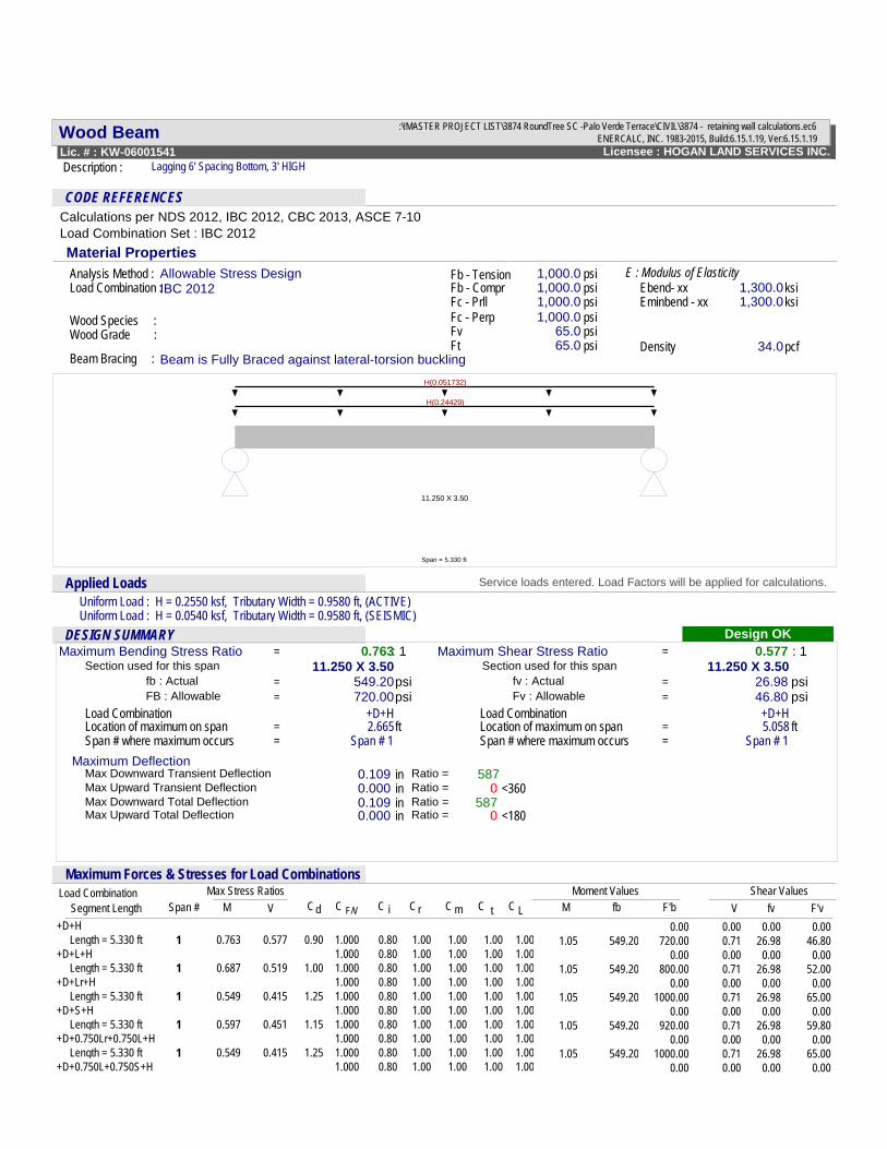
Description : Lagging 6' Spacing Bottom, 3' HIGH
CODE REFERENCESCalculations per NDS 2012, IBC 2012, CBC 2013, ASCE 7-10Load Combination Set : IBC 2012Material Properties
Beam Bracing : Beam is Fully Braced against lateral-torsion buckling
Allowable Stress Design 1,000.01,000.01,000.01,000.0
1,300.01,300.0
65.065.0 34.0
Analysis Method :
Eminbend - xx ksiWood Species :Wood Grade :
Fb - Tensionpsipsi
Fv psi
Fb - Compr
Ft psi
Fc - Prll psipsiFc - Perp
E : Modulus of ElasticityEbend- xx ksi
Density pcf
Load Combination :IBC 2012
11.250 X 3.50
Span = 5.330 ft
H(0.24429)
H(0.051732)
.Applied Loads Service loads entered. Load Factors will be applied for calculations.
Uniform Load : H = 0.2550 ksf, Tributary Width = 0.9580 ft, (ACTIVE)Uniform Load : H = 0.0540 ksf, Tributary Width = 0.9580 ft, (SEISMIC)
.DESIGN SUMMARY Design OKMaximum Bending Stress Ratio 0.763: 1
Load Combination +D+H
Span # where maximum occurs Span # 1Location of maximum on span 2.665ft
26.98 psi=
=
FB : Allowable 720.00psi Fv : Allowable
11.250 X 3.50Section used for this span
Span # where maximum occursLocation of maximum on span
Span # 1=
Load Combination +D+H=
=
=
46.80 psi==
Section used for this span 11.250 X 3.50fb : Actual
Maximum Shear Stress Ratio 0.577 : 1
5.058 ft==
549.20psi fv : Actual
Maximum Deflection
0 <360587
Ratio = 0 <180
Max Downward Transient Deflection 0.109 in 587Ratio =Max Upward Transient Deflection 0.000 in Ratio =Max Downward Total Deflection 0.109 in Ratio =Max Upward Total Deflection 0.000 in
.Maximum Forces & Stresses for Load Combinations
Span #Moment ValuesLoad Combination
C i C LC CCC F/V mr tdShear ValuesMax Stress Ratios
M CV fbM fvF'b V F'vSegment Length+D+H 0.00 0.00 0.00 0.00
1.00 Length = 5.330 ft 1 0.763 0.577 0.90 1.000 1.00 1.00 1.00 1.05 549.20 720.00 0.71 46.80 0.80 26.98 1.00+D+L+H 1.000 1.00 1.00 1.00 0.00 0.00 0.00 0.80 0.00 1.00 Length = 5.330 ft 1 0.687 0.519 1.00 1.000 1.00 1.00 1.00 1.05 549.20 800.00 0.71 52.00 0.80 26.98 1.00+D+Lr+H 1.000 1.00 1.00 1.00 0.00 0.00 0.00 0.80 0.00 1.00 Length = 5.330 ft 1 0.549 0.415 1.25 1.000 1.00 1.00 1.00 1.05 549.20 1000.00 0.71 65.00 0.80 26.98 1.00+D+S+H 1.000 1.00 1.00 1.00 0.00 0.00 0.00 0.80 0.00 1.00 Length = 5.330 ft 1 0.597 0.451 1.15 1.000 1.00 1.00 1.00 1.05 549.20 920.00 0.71 59.80 0.80 26.98 1.00+D+0.750Lr+0.750L+H 1.000 1.00 1.00 1.00 0.00 0.00 0.00 0.80 0.00 1.00 Length = 5.330 ft 1 0.549 0.415 1.25 1.000 1.00 1.00 1.00 1.05 549.20 1000.00 0.71 65.00 0.80 26.98 1.00+D+0.750L+0.750S+H 1.000 1.00 1.00 1.00 0.00 0.00 0.00 0.80 0.00
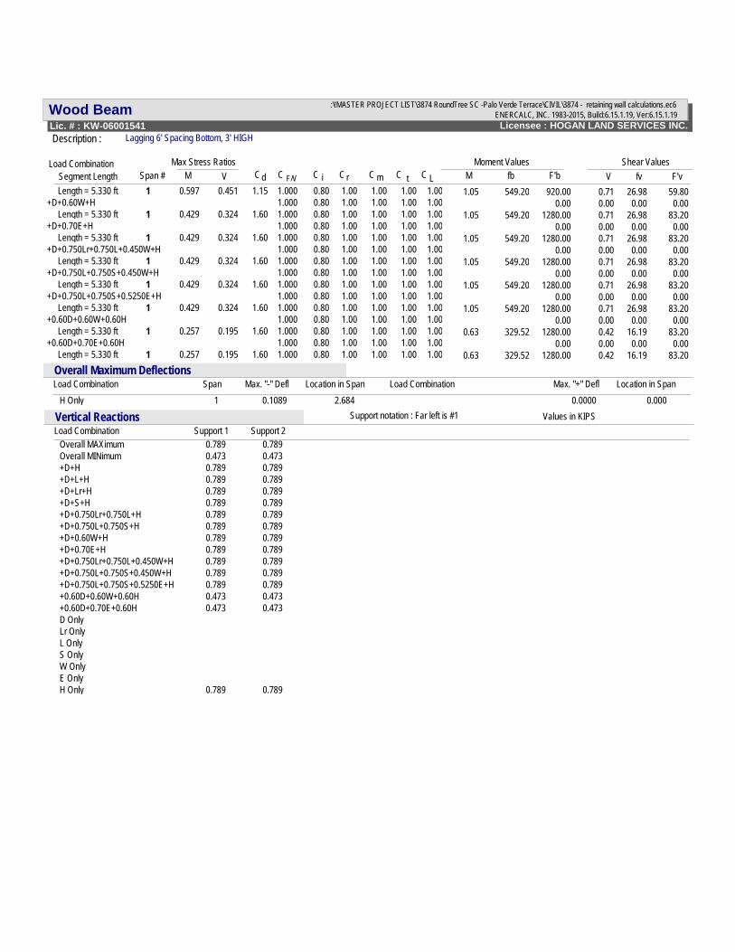
Wood Beam ENERCALC, INC. 1983-2015, Build:6.15.1.19, Ver:6.15.1.19Licensee : HOGAN LAND SERVICES INC.Lic. # : KW-06001541
File = S:\!MASTER PROJECT LIST\3874 RoundTree SC -Palo Verde Terrace\CIVIL\3874 - retaining wall calculations.ec6
Description : Lagging 6' Spacing Bottom, 3' HIGH
Span #Moment ValuesLoad Combination
C i C LC CCC F/V mr tdShear ValuesMax Stress Ratios
M CV fbM fvF'b V F'vSegment Length 1.00 Length = 5.330 ft 1 0.597 0.451 1.15 1.000 1.00 1.00 1.00 1.05 549.20 920.00 0.71 59.80 0.80 26.98 1.00+D+0.60W+H 1.000 1.00 1.00 1.00 0.00 0.00 0.00 0.80 0.00 1.00 Length = 5.330 ft 1 0.429 0.324 1.60 1.000 1.00 1.00 1.00 1.05 549.20 1280.00 0.71 83.20 0.80 26.98 1.00+D+0.70E+H 1.000 1.00 1.00 1.00 0.00 0.00 0.00 0.80 0.00 1.00 Length = 5.330 ft 1 0.429 0.324 1.60 1.000 1.00 1.00 1.00 1.05 549.20 1280.00 0.71 83.20 0.80 26.98 1.00+D+0.750Lr+0.750L+0.450W+H 1.000 1.00 1.00 1.00 0.00 0.00 0.00 0.80 0.00 1.00 Length = 5.330 ft 1 0.429 0.324 1.60 1.000 1.00 1.00 1.00 1.05 549.20 1280.00 0.71 83.20 0.80 26.98 1.00+D+0.750L+0.750S+0.450W+H 1.000 1.00 1.00 1.00 0.00 0.00 0.00 0.80 0.00 1.00 Length = 5.330 ft 1 0.429 0.324 1.60 1.000 1.00 1.00 1.00 1.05 549.20 1280.00 0.71 83.20 0.80 26.98 1.00+D+0.750L+0.750S+0.5250E+H 1.000 1.00 1.00 1.00 0.00 0.00 0.00 0.80 0.00 1.00 Length = 5.330 ft 1 0.429 0.324 1.60 1.000 1.00 1.00 1.00 1.05 549.20 1280.00 0.71 83.20 0.80 26.98 1.00+0.60D+0.60W+0.60H 1.000 1.00 1.00 1.00 0.00 0.00 0.00 0.80 0.00 1.00 Length = 5.330 ft 1 0.257 0.195 1.60 1.000 1.00 1.00 1.00 0.63 329.52 1280.00 0.42 83.20 0.80 16.19 1.00+0.60D+0.70E+0.60H 1.000 1.00 1.00 1.00 0.00 0.00 0.00 0.80 0.00 1.00 Length = 5.330 ft 1 0.257 0.195 1.60 1.000 1.00 1.00 1.00 0.63 329.52 1280.00 0.42 83.20 0.80 16.19
.Location in SpanLoad CombinationMax. "-" Defl Location in SpanLoad Combination Span Max. "+" Defl
Overall Maximum Deflections
H Only 1 0.1089 2.684 0.0000 0.000.
Load Combination Support 1 Support 2Vertical Reactions Support notation : Far left is #1 Values in KIPS
Overall MAXimum 0.789 0.789Overall MINimum 0.473 0.473+D+H 0.789 0.789+D+L+H 0.789 0.789+D+Lr+H 0.789 0.789+D+S+H 0.789 0.789+D+0.750Lr+0.750L+H 0.789 0.789+D+0.750L+0.750S+H 0.789 0.789+D+0.60W+H 0.789 0.789+D+0.70E+H 0.789 0.789+D+0.750Lr+0.750L+0.450W+H 0.789 0.789+D+0.750L+0.750S+0.450W+H 0.789 0.789+D+0.750L+0.750S+0.5250E+H 0.789 0.789+0.60D+0.60W+0.60H 0.473 0.473+0.60D+0.70E+0.60H 0.473 0.473D OnlyLr OnlyL OnlyS OnlyW OnlyE OnlyH Only 0.789 0.789