design criteria of standard earth retaining systems
TRANSCRIPT

5-5 Design Criteria of stanDarD earth retaining systems 1
MeMo to Designers 5-5 • April 2014
LRFD
5-5 Design Criteria of stanDarD earth retaining systems
IntroductionWith the implementation of AASHTO Load and Resistance Factor Design (LRFD) Bridge Design Specifications (AASHTO Design Specifications) a new set of Earth Retaining Systems (ERS) have been produced and published as Standard Plans or Revised Standard Plans. Similarly, a new set of Bridge Standard Details (XS sheets) related to ERS have been produced and added to the working set of Bridge Standard Details. This memo summarizes the design criteria and assumptions used to produce the new plans. This memo is not intended to include every aspect of design in the AASHTO Design Specifications, nor is this memo intended as a substitute for the AASHTO Design Specifications.
The design parameters for design of these ERS are based on the AASHTO Design Specifications, 4th edition, 2007, and the 2010 California Amendments (California Amendments).
ERS that appear as 2010 Standard Plans or Revised Standard Plans are:
• Retaining Walls – Type 1, 1A, 5 and 6
• Crib Walls – made of reinforced concrete or steel
ERS that appear as Bridge Standard Details are
• Retaining Walls – Type 7
• Modified Retaining Walls supporting sound walls, Type 1SW series and Type 5SW series and Type 7SW series
• Mechanically Stabilized Embankment (MSE)
Design Parameters and Assumptionsa) Material PropertiesThe soil parameters and material properties assumed for design purposes are consistent with the 2010 Standard Specifications and Standard Special Provisions. Accordingly, these values are the default values utilized in the design of the Standard Plans and the Bridge Standard Details. Project specific parameters must be used when materials available for use on that project result in greater force effects on ERS, and the standard designs should be re-evaluated for the project in such cases.

MeMo to Designers 5-5 • April 2014
2 5-5 Design Criteria of stanDarD earth retaining systems
LRFD
Soil Backfill Parameters• Unit Weight of Soil, γs = 120 pcf
• Soil Cohesion, c = 0
• Internal friction angle, ϕ =34° for the backfill and foundation soil of all ERS except MSE
• Internal friction angle, ϕ =34° for the reinforced soil of MSE
• Internal friction angle, ϕ =30° for the retained soil (behind the reinforced soil) and foundation soil (below the reinforced soil) of MSE
Material Properties of Reinforced Concrete Elements• Compressive Strength of Concrete at 28 days , fc' = 3.6 ksi (4.0 ksi for MSE panels)
• Reinforced Concrete Unit Weight, γc = 150 pcf
• Minimum Yield Strength of Reinforcing Steel, fy = 60 ksi
b) Drainage and CompactionSufficient and appropriate drainage details are assumed to be provided in the reinforced soil and the retained soil. Hence no water pressure is considered in the design. Also, no compaction loads are considered in the design, since the construction methods allowed in the Standard Specifications prevent inducing any additional stress in the structures.
Standard Design Considerations
a) Limit States and Load CombinationsService Limit State I, Strength Limit State I and Extreme Event Limit State I (earthquake) shown in Table 3.4.1-1 of the California Amendments were considered for design of all standard ERS retaining backfill supporting highway traffic. Note that load combination Strength IV in Table 3.4.1-1is not applicable to ERS. The load combinations used were,
Service Limit State I 1.0DC+1.0EV+1.0EH +1.0LS
5-5 Design Criteria of stanDarD earth retaining systems 3
MeMo to Designers 5-5 • April 2014
LRFD
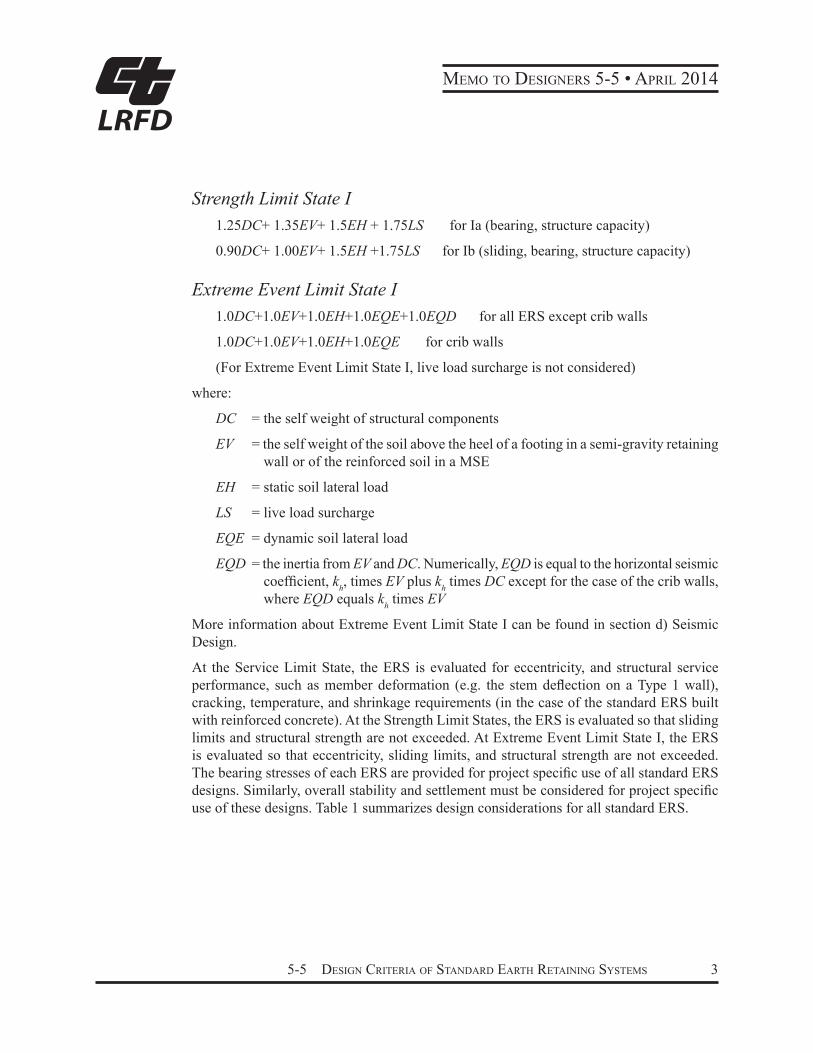
Strength Limit State I 1.25DC+ 1.35EV+ 1.5EH + 1.75LS for Ia (bearing, structure capacity)
0.90DC+ 1.00EV+ 1.5EH +1.75LS for Ib (sliding, bearing, structure capacity)
Extreme Event Limit State I 1.0DC+1.0EV+1.0EH+1.0EQE+1.0EQD for all ERS except crib walls
1.0DC+1.0EV+1.0EH+1.0EQE for crib walls
(For Extreme Event Limit State I, live load surcharge is not considered)
where:
DC = the self weight of structural components
EV = the self weight of the soil above the heel of a footing in a semi-gravity retaining wall or of the reinforced soil in a MSE
EH = static soil lateral load
LS = live load surcharge
EQE = dynamic soil lateral load
EQD = the inertia from EV and DC. Numerically, EQD is equal to the horizontal seismic coefficient, kh, times EV plus kh times DC except for the case of the crib walls, where EQD equals kh times EV
More information about Extreme Event Limit State I can be found in section d) Seismic Design.
At the Service Limit State, the ERS is evaluated for eccentricity, and structural service performance, such as member deformation (e.g. the stem deflection on a Type 1 wall), cracking, temperature, and shrinkage requirements (in the case of the standard ERS built with reinforced concrete). At the Strength Limit States, the ERS is evaluated so that sliding limits and structural strength are not exceeded. At Extreme Event Limit State I, the ERS is evaluated so that eccentricity, sliding limits, and structural strength are not exceeded. The bearing stresses of each ERS are provided for project specific use of all standard ERS designs. Similarly, overall stability and settlement must be considered for project specific use of these designs. Table 1 summarizes design considerations for all standard ERS.

MeMo to Designers 5-5 • April 2014
4 5-5 Design Criteria of stanDarD earth retaining systems
LRFD
Table 1 Analysis for ERS Design
Limit State Service I Strength Ia Strength Ib Extreme Event I (Seismic)
Bearing Stresses* X X X X
Eccentricity X XSliding X XStructural Service Performance
X
Structural Capacity X X X
* To be checked against actual project conditions before use of the Standard
Load combinations for concrete retaining walls supporting sound walls or containing ground anchors have slightly different load combinations than other standard ERS. The load combinations for those ERS include force effects of the wind load on the sound wall, the inertial force of the sound wall for seismic events, and the prestress force from the vertical ground anchors. These walls form part of the Bridge Standard Details (XS sheets), and their respective loading can be found on those sheets.
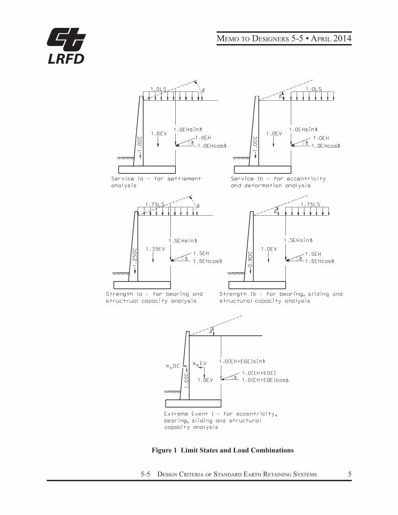
Load factors are chosen to create maximum force effect for a given load combination. Strength Limit State I is separated into Strength Ia and Strength Ib using load factor values as shown in Figure 1. These load combinations are also illustrated in Section C11.5.5 of the AASHTO Design Specifications. The loads depicted in Figure 1 are shown applied to a semi-gravity wall, but are applied to all standard ERS.
5-5 Design Criteria of stanDarD earth retaining systems 5
MeMo to Designers 5-5 • April 2014
LRFD
Figure 1 Limit States and Load Combinations
MeMo to Designers 5-5 • April 2014
6 5-5 Design Criteria of stanDarD earth retaining systems
LRFD
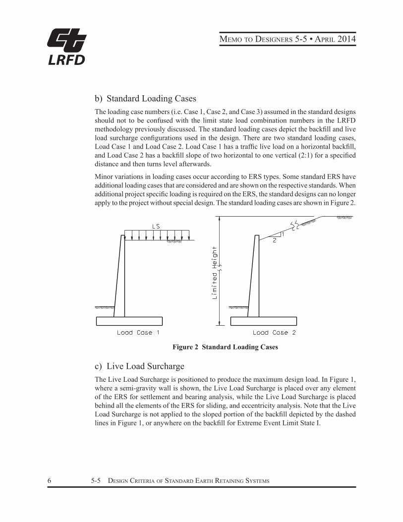
b) Standard Loading CasesThe loading case numbers (i.e. Case 1, Case 2, and Case 3) assumed in the standard designs should not to be confused with the limit state load combination numbers in the LRFD methodology previously discussed. The standard loading cases depict the backfill and live load surcharge configurations used in the design. There are two standard loading cases, Load Case 1 and Load Case 2. Load Case 1 has a traffic live load on a horizontal backfill, and Load Case 2 has a backfill slope of two horizontal to one vertical (2:1) for a specified distance and then turns level afterwards.
Minor variations in loading cases occur according to ERS types. Some standard ERS have additional loading cases that are considered and are shown on the respective standards. When additional project specific loading is required on the ERS, the standard designs can no longer apply to the project without special design. The standard loading cases are shown in Figure 2.
Figure 2 Standard Loading Cases
c) Live Load SurchargeThe Live Load Surcharge is positioned to produce the maximum design load. In Figure 1, where a semi-gravity wall is shown, the Live Load Surcharge is placed over any element of the ERS for settlement and bearing analysis, while the Live Load Surcharge is placed behind all the elements of the ERS for sliding, and eccentricity analysis. Note that the Live Load Surcharge is not applied to the sloped portion of the backfill depicted by the dashed lines in Figure 1, or anywhere on the backfill for Extreme Event Limit State I.

5-5 Design Criteria of stanDarD earth retaining systems 7
MeMo to Designers 5-5 • April 2014
LRFD
d) Seismic DesignThe seismic design of the standard ERS is performed using either Mononobe-Okabe (MO) Method for Loading Case 1 (a backfill with a planar surface and no live load surcharge), or the trial wedge method for Loading Case 2. The Trial Wedge Method is similar to the MO Method and is used for the other Loading Cases where the backfill surface is not planar.
As a result of analysis using the MO Method, the resultant of seismic soil pressure, PAE, is obtained. All standard ERS are designed using the criteria in the 2010 California Amendments for seismic load. The 2010 California Amendments assumes that the total soil thrust, PAE, is separated into two components, the static active soil pressure in a triangular shape and the dynamic soil pressure in a rectangular shape, as shown in Figure 3.
dynamic soil
pressure
H
static soil
pressure
total soil
pressure
+ =
1 3H1 2H ha
PAE
Figure 3 Seismic Loading (Reference: 2010 California Amendments)
Therefore, the total soil lateral load estimated using the MO method or a similar trial wedge method was a function of the horizontal seismic coefficient, kh, the vertical seismic coefficient, kv , and the soil internal friction angle, ϕ. However, kv was assumed to be zero for most cases because horizontal and vertical accelerations are assumed not to occur simultaneously. For a large kh or for an infinitely long and steep backfill slope, numerical difficulty occurs and both the MO method and the trial wedge methods yield no solution. In reality a slope is seldom infinitely long. The numerical difficulty can then be circumvented by assuming the backfill surface levels off after rising to a specified height above the ERS so the trial wedge method can be employed.
Most standard ERS are designed assuming a kh equal to 0.2, except for concrete retaining walls supporting sound walls where a kh of 0.3 is assumed in the design. A kh of 0.2 is usually adequate for ERS built in most parts of California where no additional surcharges are present or structure movements are not restricted. When the inertia of the structural member and the

MeMo to Designers 5-5 • April 2014
8 5-5 Design Criteria of stanDarD earth retaining systems
LRFD
affected soil is included in the seismic design, the inertial force is assumed to act at their respective center of gravity.
ERS Type-Specific Design ConsiderationsThe following describes design assumptions specific to various ERS types.
a) Semi-Gravity Retaining Walls
Additional Loading CaseIn the case of semi-gravity concrete retaining walls such as Standard Plan Type 1, there is an additional loading case considered. Along with Load Case 1 - Horizontal Backfill, and Load Case 2 - Sloped Backfill of 2 horizontal to 1 vertical and limited to a vertical height of 40 feet for the slope, there is also a Load Case 3 with a broken sloped backfill up to 5 feet, as shown in Figure 4.
Figure 4 Loading Case 3 for Type 1 and Type 5 Retaining Walls
Live Load SurchargeThe effect of the design truck and design lane on soil acting on the ERS for Load Case 1 has been considered by applying an equivalent uniform soil layer on top of the retained soil, and has been defined as Live Load Surcharge (LS). The depth of such a layer depends on the distance from the edge of the traffic to a vertical line where the soil pressure is evaluated and on the height of the ERS. Table 3.11.6.4-2 in the AASHTO LRFD Design Specifications (2007) lists equivalent soil heights for vehicular loading on ERS.

5-5 Design Criteria of stanDarD earth retaining systems 9
MeMo to Designers 5-5 • April 2014
LRFD
Sliding ResistanceFor semi-gravity walls sliding resistance is provided by passive resistance on the footing and shear key, as well as the friction between the footing and the foundation soil. When calculating the passive resistance, the passive force provided by the soil over the top of the footing is ignored because the material in this region is often disturbed and hence the passive force of this region is not reliable. However, the contribution of the weight of this portion of the soil is considered in calculating the passive resistance of the soil in front of the footing and the shear key. Figure 5 shows how the passive resistance is calculated. The arrows in the pressure diagram in front of the footing and the shear key denote the passive pressure contributing to the passive resistance. (For other types of ERS the passive resistance is ignored and only the friction at the bottom of the wall is considered in resisting sliding.)
Figure 5 Passive Resistance on Footing and Shear Key
In the past, friction resistance at the bottom of a semi-gravity wall was provided by two separate parts, all being a function of the magnitude of the normal pressure on the bottom of the footing. The first part was based on the friction from the toe to the left edge of the shear key. A coefficient of friction equal to the tangent of the soil friction angle was used when calculating this part of the friction resistance. The second part was based on the friction for the remainder of the footing width, using a coefficient of friction equal to the tangent of two-thirds the soil friction angle. The first part was assumed to be based on soil-on-soil friction, while the second part as based on soil-on-footing friction. The bottom of the footing, however, is rough, unlike other parts of the wall such as the stem with smooth surfaces. Hence the reduced friction coefficient of the second part is not warranted. The friction coefficient for the 2010 semi-gravity walls is assumed to be the same along the entire width of the footing and is not reduced.

MeMo to Designers 5-5 • April 2014
10 5-5 Design Criteria of stanDarD earth retaining systems
LRFD
Extreme Event Limit State IIIn the case of semi-gravity concrete walls with level backfill on which highway traffic is present, solid traffic barriers (e.g. type 736, 742, etc.) may be integrally mounted on top of the stem. The vehicular collision force on the barrier must be considered in the design of the walls. This load combination falls in the category of extreme event limit state II, hence the load factor is 1.0. Live load surcharge is not considered in this load combination. The load combination involving vehicular collision in standard plan wall design is,
1.0EH+1.0DC+1.0EV +1.0CT
where:
CT = the vehicular collision load of 54 kips corresponding to a Test Level 4 load
At Extreme Event Limit State II, the ERS is evaluated so that bearing capacity, sliding requirements, and structural strength are not exceeded.
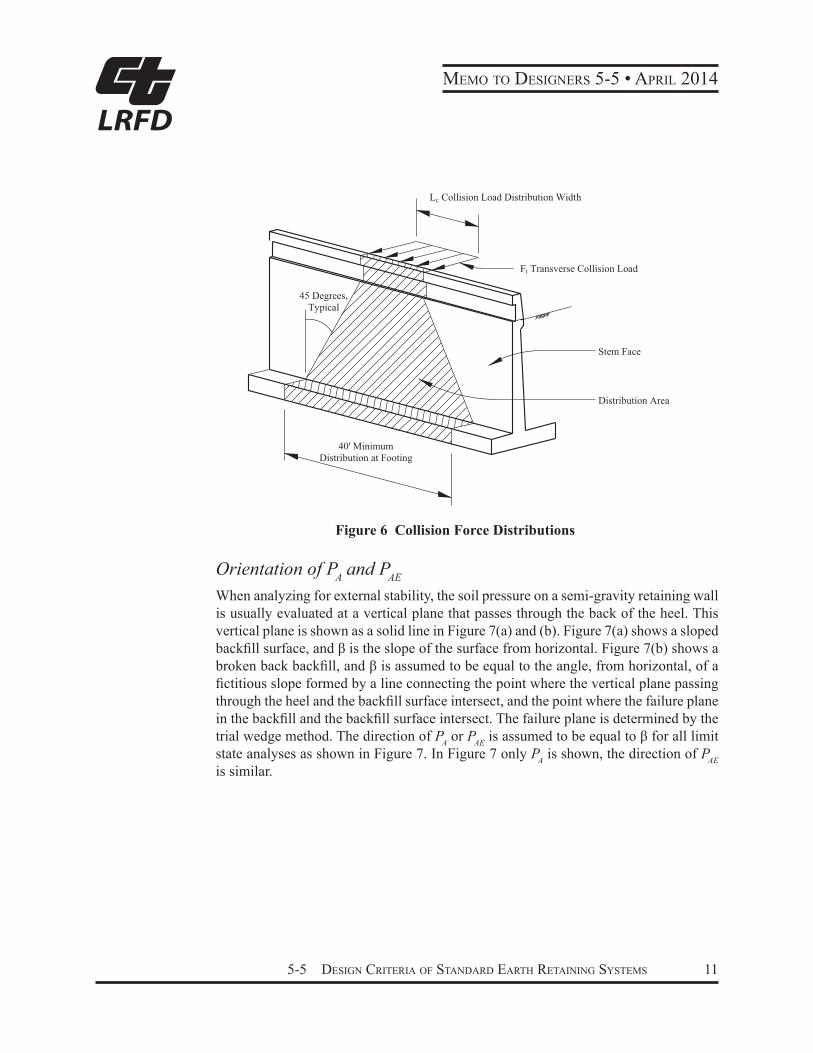
The collision force (CT) is assumed to be distributed over a length of 10 feet at top of the stem for a solid barrier and is assumed to spread downward to the top of the footing at a 45 degree angle. The spread limits thus constitute the contributory length of the wall resisting the collision force. Figure 6 illustrates how the collision force is distributed down the wall stem. The shaded area illustrates the effective region resisting the collision force. In Figure 6, Ft is the lateral design collision load and is 54 kips corresponding to Test Level 4 (TL4). θi is the angle of the collision load spread down the wall which is assumed to be 45 degrees and Lc is the length over which the collision load is spread at the top of the stem and is assumed to be 10 feet. When calculating the moment of the stem, the moment arm is measured from 32 inches above the toe of the barrier to the point on the stem where the moment is evaluated.
5-5 Design Criteria of stanDarD earth retaining systems 11
MeMo to Designers 5-5 • April 2014
LRFD
Ft Transverse Collision Load
Lc Collision Load Distribution Width
Stem Face
Distribution Area
40' Minimum Distribution at Footing
45 Degrees, Typical
Figure 6 Collision Force Distributions
Orientation of PA and PAE
When analyzing for external stability, the soil pressure on a semi-gravity retaining wall is usually evaluated at a vertical plane that passes through the back of the heel. This vertical plane is shown as a solid line in Figure 7(a) and (b). Figure 7(a) shows a sloped backfill surface, and β is the slope of the surface from horizontal. Figure 7(b) shows a broken back backfill, and β is assumed to be equal to the angle, from horizontal, of a fictitious slope formed by a line connecting the point where the vertical plane passing through the heel and the backfill surface intersect, and the point where the failure plane in the backfill and the backfill surface intersect. The failure plane is determined by the trial wedge method. The direction of PA or PAE is assumed to be equal to β for all limit state analyses as shown in Figure 7. In Figure 7 only PA is shown, the direction of PAE is similar.

MeMo to Designers 5-5 • April 2014
12 5-5 Design Criteria of stanDarD earth retaining systems
LRFD
Figure 7 Direction of PA or PAE for Semi-Gravity Walls
Temperature and Shrinkage ReinforcementThe amount of the temperature and shrinkage reinforcement in the footing along the length of the wall is equally distributed at the top and the bottom surfaces of the footing. The stem is divided into several zones according to the stem thickness. Two thirds of this reinforcement is placed at the front face of the stem that is exposed to the elements and the remaining on the backfill side. Layout of the reinforcement is consistent with the long time practice for this type of the retaining walls developed by the Caltrans, and with the provisions in ACI 318-08.
b) Concrete Crib and Steel Bin WallsConcrete crib and steel bin walls are old technology, therefore, only the basic AASHTO design provisions are provided for these designs. Consequently, the modified silo theory was utilized for the design of both the steel bin and the concrete open crib and closed crib walls. Standard timber walls were discontinued due to durability, redundancy, and fire resistance concerns.
In silo theory a portion of the weight of the backfill “soil plug” in the center of the bin or crib loads the walls through frictional contact with the rough and irregular surface of the walls composing the bin or crib. The rest of the “soil plug” rests on the foundation soil through the open bottom. These combine to create a highly irregular contact pressure diagram. A generalized uniform pressure is reported for practical application.
5-5 Design Criteria of stanDarD earth retaining systems 13
MeMo to Designers 5-5 • April 2014
LRFD
Designing the base of the walls of the bin or crib is difficult as the mathematical analyses often indicates that failure will occur but is not seen in practice when constructed on yielding foundation soils. Therefore, the design assumes the foundation soil must give sufficiently to allow the corner base plate or bottom most crib member to slightly punch into the foundation soil enough to transfer the loading back to the “soil plug” and avoid deformation failure. This design cannot be used directly on solid rock, nor a concrete slab, without a special soil layer designed as its foundation.
Drainage must be provided in these designs especially when the facing closure member is selected for use. The special backfill gradation in the construction specifications typically provides for sufficient drainage in open cribs and bins from within the structure. The materials behind and underneath must still be adequately drained for the unsaturated conditions assumed during design. Care must be taken when selecting a different backfill for inside these systems so that both the weight and the drainage requirements are maintained.
No collision loading on traffic barriers or rail is included in these designs. The Load Case 1 condition is modified to provide sufficient soil separation from the traffic to the top members of the bin or crib. Additionally, one of the benefits of these designs is the ability to deform in service. All design details are modeled as pinned to maintain this deformation ability. Support of any rigid loading physically attached to these structures was not considered in design and doing so would constitute a special design. Historically this type of loading has not been allowed.
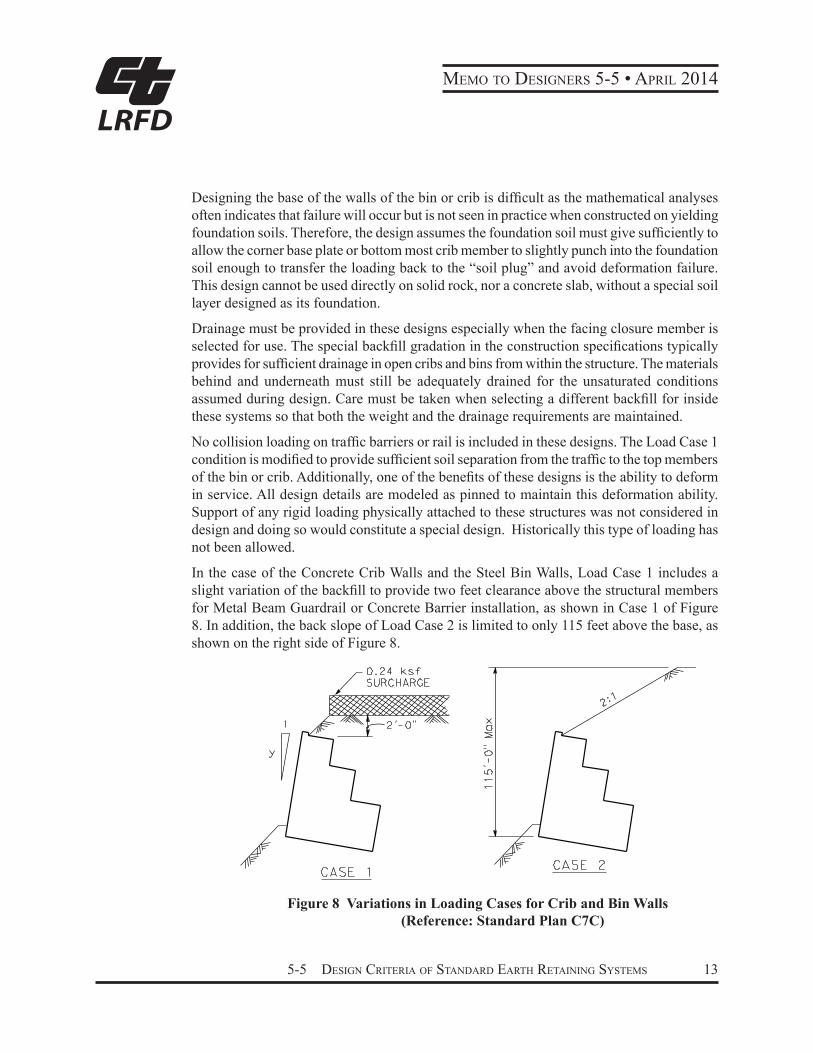
In the case of the Concrete Crib Walls and the Steel Bin Walls, Load Case 1 includes a slight variation of the backfill to provide two feet clearance above the structural members for Metal Beam Guardrail or Concrete Barrier installation, as shown in Case 1 of Figure 8. In addition, the back slope of Load Case 2 is limited to only 115 feet above the base, as shown on the right side of Figure 8.
Figure 8 Variations in Loading Cases for Crib and Bin Walls (Reference: Standard Plan C7C)

MeMo to Designers 5-5 • April 2014
14 5-5 Design Criteria of stanDarD earth retaining systems
LRFD
Orientation of PA and PAE
In the case of single cell crib and bin walls, the plane where the soil lateral pressure is applied is the backside of the cell. The δ for PA and PAE is taken as 0.5 of the soil friction angle, ϕ. In the case of multiple cell crib walls, the plane of soil lateral pressure application is a plane connecting the top back corner of the topmost cell and the bottom back corner of the bottom cell, as shown in Figure 9. The δ for PA and PAE is taken as 0.75 of ϕ.
Figure 9 Single and Multiple Cell Crib and Bin Walls (Reference: AASHTO 2007)
c) Mechanically Stabilized Embankment (MSE)In the case of MSE, the Coherent Gravity Method (CGM) is utilized for internal design with metallic soil reinforcement. All the resistance factors for the tensile resistance of the soil reinforcement and connections are amended. Refer to Table 11.5.6-1 and Section 11.5.7 in the California Amendment for the resistance factor values.
The design life of the MSE soil reinforcement is increased to 75 years.

5-5 Design Criteria of stanDarD earth retaining systems 15
MeMo to Designers 5-5 • April 2014
LRFD
For Load Case 1, the standard MSE design height is increased by 1'-8'', measured from the top of the top panels to the roadway surface, in order to accommodate the traffic barrier attached to a concrete slab floating above the MSE. The concrete barrier slab design used is shown on XS12-090. The increase over prior practice will also reduce the potential conflict between the roadbed base layers and the reinforcement by providing typically 35 inches of cover over the topmost layer of soil reinforcement, as shown in Figure 10. This change increases the overburden pressure used in the design of the MSE in addition to the live load surcharge. For Load Case 2 the simple coping remains the same as in prior practice, no additional height was utilized.
Per project needs
20 inches for slab and roadway sec�on
15 inches above top reinforcement
6 to 30 inches between top and 2nd levels
30 inches between all middle levels
15 inches below bo�om level
Traffic surcharge
Load Case 1
b
Embedment
H
BW ≥ L + 18 inches
L ≥ 0.7 H
H1
Figure 10 Additional Overburden Height for Roadbed and Barrier Slab (Reference BDA 3-8)
The base width (BW) in Figure 10 is no longer synonymous with the length of the soil reinforcement. The design assumes the BW will be used to set the MSE on site and move utilities, sign foundations and so forth as needed. The BW includes the facing thickness, the reinforcement length, and at least 1 foot of the reinforced backfill behind the end of the steel reinforcement which separates the reinforcement from the retained backfill that might be chemically aggressive to the steel. BW in Figure 10 assumes a panel thickness of 6 inches.
Passive pressure is ignored at the front base of the MSE during all stability analyses, since erosion and various maintenance activities can remove the fill during the MSE’s service life. A minimum embedment is still required to reduce the potential of undermining at the toe during the MSE’s service life.
No vehicular collision loading is applied to the MSE. The barrier slab system is placed on top in the Load Case 1 condition. Under collision forces, the dynamic analysis of the barrier
MeMo to Designers 5-5 • April 2014
16 5-5 Design Criteria of stanDarD earth retaining systems
LRFD
slab shows that the vehicle briefly lost contact with the slab during collision when it was redirected back onto the roadway. This temporarily lifts the slab slightly from the backfill soil and negates friction force transfer into the MSE. Additionally, the notch used to recess the top panels into the slab in the previous design has been removed from the bottom of the slab to disengage the load transfer to the back of the facing panels. If the slab is to be buried and rotation off the soil is prevented, the MSE will need to be specially designed to include the collision load.
The 2010 Standard Specifications for construction of MSE allow for finer soils with slightly more aggressive corrosion behavior than the AASHTO construction specifications during design. Thus the MSE design continues to apply the corrosion loss equations that correspond to these more aggressive backfill soils (California Amendments 11.10.6.4.2a). It is anticipated that the backfill soil specifications will be revisited after the corrosion study into the actual lifetime corrosion of metallic MSE reinforcement in California is complete.
Bridge Design Aids 3-8 contains information about standard MSE using 5ft by 5ft concrete panels and steel soil reinforcement. The MSE design details, design considerations, inspection wire locations and internal drainage requirements and design check lists can also be found in BDA 3-8.

5-5 Design Criteria of stanDarD earth retaining systems 17
MeMo to Designers 5-5 • April 2014
LRFD
References1. AASHTO LRD Bridge Design Specifications, 4th Edition, American Association of
State Highway Transportation Officials, 2007.
2. Bridge Design Specifications, LFD Version, Department of Transportation, State of California, April 2000.
3. Bridge Memo to Designers, 22-1 Soundwall Design Criteria, Department of Transportation, State of California, August 2004.
4. Bridge Standard Detail Sheets (XS), California Department of Transportation, on-line at www.dot.ca.gov.
5. California Amendments to the AASHTO LRD Bridge Design Specifications, 4th Edition, Department of Transportation, State of California, September 2010.
6. Corrosion Guidelines, Version 1, California Department of Transportation, Division of Engineering Services, Materials Engineering and Testing Services, Corrosion Technology Branch, September 2003.
7. MSEW, Version 3, ADAMA Engineering, Inc, 2007.
8. Standard Plans, 2010 Edition, California Department of Transportation, on-line at www.dot.ca.gov , 2011.
9. Building Code Requirements for Structural Concrete (ACI 318-08), American Concrete Institute, 2008.
_________________________________Barton J. NewtonState Bridge EngineerDeputy Division Chief, Structure Policy & InnovationDivision of Engineering Services
Original signed by Barton J. Newton