design - lifepositive.com data and produce the required report on a hard copy or display it on the...
TRANSCRIPT

1
DESIGN
INTRODUCTION
Software design sits at the technical kernel of the software engineering process and is applied
regardless of the development paradigm and area of application. Design is the first step in the
development phase for any engineered product or system. The designer’s goal is to produce a
model or representation of an entity that will later be built. Beginning, once system requirement
has been specified and analyzed, system design is the first of the three technical activities -
design, code and test that is required to build and verify software.
The importance can be stated with a single word “Quality”. Design is the place where quality
is fostered in software development. Design provides us with representations of software that
can assess for quality. Design is the only way that we can accurately translate a customer’s
view into a finished software product or system. Software design serves as a foundation for all
the software engineering steps that follow. Without a strong design, we risk building an
unstable system – one that will be difficult to test, one whose quality cannot be assessed until
the last stage.
During design, progressive refinement of data structure, program structure, and procedural
details are developed reviewed and documented. System design can be viewed from either
technical or project management perspective. From the technical point of view, design is
comprised of four activities – architectural design, data structure design, interface design and
procedural design.
❖ SYSTEM DESIGN
System design is the solution for the creation of a new system. This phase focuses on the
detailed implementation of the feasible system.
It emphasis on translating design. Specifications to performance specification. System design
has two phases of development
• Logical design
• Physical design
2
During logical design phase the analyst describes inputs (sources), output s(destinations),
databases (data sores) and procedures (dataflows) all in a format that meets the user
requirements. The analyst also specifies the needs of the user at a level that virtually determines
the information flow in and out of the system and the data resources. Here the logical design is
done through data flow diagrams and database design. The physical design is followed by
physical design or coding. Physical design produces the working system by defining the design
specifications, which specify exactly what the candidate system must do. The programmers
write the necessary programs that accept input from the user, perform necessary processing on
accepted data and produce the required report on a hard copy or display it on the screen.
❖ INPUT AND OUTPUT DESIGN
INPUT DESIGN:
Input design is the link that ties the information system into the world of its users. The input
design involves determining the inputs, validating the data, minimizing the data entry and
provides a multi-user facility. Inaccurate inputs are the most common cause of errors in data
processing. Errors entered by the data entry operators can be controlled by input design. The
user-originated inputs are converted to a computer based format in the input design. Input data
are collected and organized into groups of similar data. Once identified, the appropriate input
media are selected for processing. All the input data are validated and if any data violates any
conditions, the user is warned by a message. If the data satisfies all the conditions, it is
transferred to the appropriate tables in the database. In this project the student details are to be
entered at the time of registration. A page is designed for this purpose which is user friendly
and easy to use. The design is done such that users get appropriate messages when exceptions
occur.
OUTPUT DESIGN:
Computer output is the most important and direct source of information to the user. Output
design is a very important phase since the output needs to be in an efficient manner. Efficient
and intelligible output design improves the system relationship with the user and helps in
decision making. Allowing the user to view the sample screen is important because the user is
the ultimate judge of the quality of output. The output module of this system is the selected
notifications.
3
❖ DATABASE DESIGN:
Databases are the storehouses of data used in the software systems. The data is stored in tables
inside the database. Several tables are created for the manipulation of the data for the system.
Two essential settings for a database are the field that is unique for all the record occurrences.
the field used to set relation between tables. Normalization is a technique to avoid redundancy
in the tables.
❖ SYSTEM TOOLS
The various system tools that have been used in developing both the frontend and the back end
of the project are being discussed in this chapter.
FRONT END:
PHP, HTML, CSS, JAVA SCRIPT are utilized to implement the frontend.
PHP (Hypertext Pre-processor): PHP is a widely-used open source general-purpose scripting
language that is especially suited for web development and can be embedded into HTML.
HTML (Hyper Text Mark-up Language): HTML is a syntax used to format a text document
on the web.
CSS (Cascading Style Sheets): CSS is a style sheet language used for describing the look and
formatting of a document written in a mark-up language.
Java Script: JS is a dynamic computer programming language. It is most commonly used as
part of web browsers, whose implementations allow client-side scripts to interact with the user,
control the browser, communicate asynchronously, and alter the document content that is
displayed. Java Script is used to create pop-up windows displaying different alerts in
BACK END
The back end is implemented using MySQL which is used to design the databases.
MySQL: MySQL is the world's second most widely used open-source relational database
management system (RDBMS). The SQL phrase stands for Structured Query Language.

4
INPUT DESIGN:
Input design is a part of overall system design. The main objective during the input design is
as given below:
• To produce a cost-effective method of input.
• To achieve the highest possible level of accuracy.
• To ensure that the input is acceptable and understood by the user.
INPUT STAGES:
The main input stages can be listed as below:
• Data recording
• Data transcription
• Data conversion
• Data verification
• Data control
• Data transmission
• Data validation
• Data correction
INPUT TYPES:
It is necessary to determine the several types of inputs. Inputs can be categorized as follows:
• External inputs, which are prime inputs for the system.
• Internal inputs, which are user communications with the system.
• Operational, which are computer department’s communications to the system?
• Interactive, which are inputs entered during a dialogue.

5
INPUT MEDIA:
At this stage choice must be made about the input media. To conclude about the input media
consideration must be given to;
• Type of input
• Flexibility of format
• Speed
• Accuracy
• Verification methods
• Rejection rates
• Ease of correction
• Storage and handling requirements
• Security
• Easy to use
• Portability
Keeping in view the above description of the input types and input media, it can be said that
most of the inputs are of the form of internal and interactive. As Input data is to be the directly
keyed in by the user, the keyboard can be the most suitable input device.
OUTPUT DESIGN:
Outputs from computer systems are required primarily to communicate the results of
processing to users. They are also used to provide a permanent copy of the results for later
consultation.
The several types of outputs in general are:
• External Outputs whose destination is outside the organization.
• Internal Outputs whose destination is within organization and they are the User’s main
interface with the computer.
• Operational outputs whose use is purely with in the computer department.
• Interface outputs, which involve the user in communicating directly with the system.

6
OUTPUT DEFINITION
The outputs should be defined in terms of the following points:
• Type of the output
• Content of the output
• Format of the output
• Location of the output
• Frequency of the output
• Volume of the output
• Sequence of the output
It is not always desirable to print or display data as it is held on a computer. It should be decided
as which form of the output is the most suitable.
OUTPUT MEDIA:
In the next stage, it is to be decided that which medium is the most appropriate for the output.
The main considerations when deciding about the output media are:
• The suitability for the device to the application.
• The need for a hard copy.
• The response time required.
• The location of the users
• The software and hardware available.
Keeping in view the above description the project is to have outputs mainly coming under the
category of internal outputs. The main outputs desired according to the requirement
specification are: - The outputs were needed to be generated as a hard copy and as well as
queries to be viewed on the screen. Keeping in view these outputs, the format for the output is
taken from the outputs, which are currently being obtained after manual processing.
IMPLEMENTATION
This chapter includes the detailed design used to build the application. The system's design is
used to create the functions and operations of the gathered requirements in detail, including
screen layouts, business rules, process diagrams, and other documentation. The output of this
chapter describes the new system which is defined as a collection of modules and subsystems.
This design stage takes the initial input requirements that were identified in the approved

7
requirements specification document. For each requirement, there is a set of one or more design
elements that are produced using the different prototypes. These design elements describe the
desired software features, in detail, including functional hierarchy diagrams, screen layouts,
activity diagrams, and class diagrams. The intention of these diagrams is to describe the
software in detail so that the system can develop the application with less additional design
input.
MODULES
A module is a separate unit of software or hardware. Typical characteristics of modular
components include portability, which allows them to be used in a variety of systems, and
interoperability, which allows them to function with the components of other systems. The
term was first used in architecture.
The system is proposed to have the following modules:
Administrator module
Customer module
Reviews module.
❖ ADMINISTRATOR MODULE:
This module provides administrator related functionality. Administrator manages all
information and has access rights to add, delete, edit and view the data related to places,
packages, routes, bookings, etc.
• registration(Login)
• Manage User
• Manage Tour-package
• Manage Ticket Booking
• Manage Payment
• View Cancellation
• View feedback

8
❖ CUSTOMER MODULE:
• Registration(Login) - Registration
• View package -Login
• Search package -manage tour
• Booking - Manage tour package cost
• Give Payment - Manage Bus(travels)
• Booking Cancellation
• Give Feedback
❖ REVIEWS MODULE:
Users of this application can post their opinions, complaints and suggestions regarding this
portal and services to the administrator. Accordingly, the administrator can take various steps
to act on the complaints and suggestions.

9
USECASE
In software and systems engineering, a use case is a list of actions or event steps, typically
defining the interactions between a role (known in the Unified Modeling Language as an
actor) and a system, to achieve a goal. The actor can be a human or other external system. In
systems engineering, use cases are used at a higher level than within software engineering,
often representing missions or stakeholder goals. The detailed requirements may then be
captured in the Systems Modeling Language (SysML) or as contractual statements. A use
case is a methodology used in system analysis to identify, clarify, and organize system
requirements. The use case is made up of a set of possible sequences of interactions between
systems and users in a environment and related to a particular goal. It consists of a group of
elements that can be used together in a way that will have an effect larger than the sum of the
separate elements combined. The use case should contain all system activities that have
significance to the users. A use case can be thought of as a collection of possible scenarios
related to a goal, indeed, the use case and goal are sometimes considered to be synonymous.
USECASE1-ADMIN

10
USECASE 1-CUSTOMER (WEDDING HOTEL BOOKING)
USECASE 3-CUSTOMER (PACKAGE BOOKING)

11
USECASE 1-CUSTOMER (HOTEL BOOKING)

12
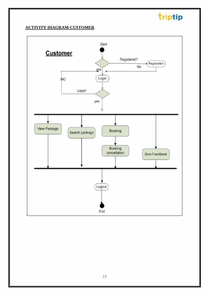
ACTIVITY DIAGRAM
The basic purposes of activity diagrams are like other four diagrams. It captures the dynamic
behavior of the system. Other four diagrams are used to show the message flow from one object
to another but activity diagram is used to show message flow from one activity to another.
Activity is an operation of the system. Activity diagrams are not only used for visualizing
dynamic nature of a system but they are also used to construct the executable system by using
forward and reverse engineering techniques. The only missing thing in activity diagram is the
message part. It does not show any message flow from one activity to another. Activity diagram
is some time considered as the flow chart. Although the diagrams look like a flow chart but it
is not. It shows different flow like parallel, branched, concurrent and single.
ACTIVITY DIAGRAM-ADMIN
13
ACTIVITY DIAGRAM-CUSTOMER
14
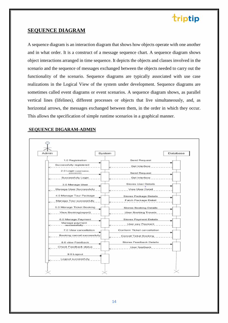
SEQUENCE DIAGRAM
A sequence diagram is an interaction diagram that shows how objects operate with one another
and in what order. It is a construct of a message sequence chart. A sequence diagram shows
object interactions arranged in time sequence. It depicts the objects and classes involved in the
scenario and the sequence of messages exchanged between the objects needed to carry out the
functionality of the scenario. Sequence diagrams are typically associated with use case
realizations in the Logical View of the system under development. Sequence diagrams are
sometimes called event diagrams or event scenarios. A sequence diagram shows, as parallel
vertical lines (lifelines), different processes or objects that live simultaneously, and, as
horizontal arrows, the messages exchanged between them, in the order in which they occur.
This allows the specification of simple runtime scenarios in a graphical manner.
SEQUENCE DIGARAM-ADMIN

15
SEQUENCE DIGARAM-CUSTOMER
16
SYSTEM TESTING
Testing is vital to the success of the system. System testing makes a logical assumption that if
all parts of the system are correct, the goal will be successfully achieved. In the testing
process, we test the actual system in an organization and gather errors from the new system
operates in full efficiency as stated. System testing is the stage of implementation, which is
aimed to ensuring that the system works accurately and efficiently.
In the testing process, we test the actual system in an organization and gather errors from the
new system and take initiatives to correct the same. All the front-end and back-end
connectivity are tested to be sure that the new system operates in full efficiency as stated.
System testing is the stage of implementation, which is aimed at ensuring that the system
works accurately and efficiently.
The main objective of testing is to uncover errors from the system. For the uncovering
process, we have to give proper input data to the system. So, we should have more conscious
to give input data. It is important to give correct inputs to efficient testing. Testing is done for
each module. After testing all the modules, the modules are integrated and testing of the final
system is done with the test data, specially designed to show that the system will operate
successfully in all its aspects conditions. Thus, the system testing is a confirmation that all is
correct and an opportunity to show the user that the system works. Inadequate testing or non-
testing leads to errors that may appear few months later. This will create two problems
• Time delay between the cause and appearance of the problem.
• The effect of the system errors on files and records within the system.
• The purpose of the system testing is to consider all the likely variations to which it
will be suggested and push the system to its limits.
• The testing process focuses on logical intervals of the software ensuring that all the
statements have been tested and on the function intervals (i.e.,) conducting tests to
uncover errors and ensure that defined inputs will produce actual results that agree
with the required results.
Testing must be done using the two common steps Unit testing and Integration testing.
17
In the project system testing is made as follows:
• The procedure level testing is made first. By giving improper inputs, the errors
occurred are noted and eliminated.
• This is the last step in system life cycle. Here we implement the tested error-free
system into real-life environment and make necessary changes, which runs in an
online fashion. Here system maintenance is done every months or year based on
company policies, and is checked for errors like runtime errors, long run errors and
other maintenances like table verification and reports.
INTRODUCTION
The most important phase in system development life cycle is system testing. The number
and nature of errors in a newly designed system depends on the system specifications and the
time frame given for the design. A newly designed system should have all the subsystems
working together, but in reality, each subsystems work independently. During this phase, all
the subsystems are gathered into one pool and tested to determine whether it meets the user
requirements. Testing is done at two level -Testing of individual modules and testing the
entire system. During the system testing, the system is used experimentally to ensure that the
software will run according to the specifications and in the way the user expects. Each test
case is designed with the intent of finding errors in the way the system will process it.
Testing plays a very critical role in determining the reliability and efficiency of software and
hence is a very important stage in software development. Software testing is done at various
levels. They are the unit testing and system testing which comprises of integration testing and
acceptance testing.
TYPES OF TESTING
• UNIT TESTING
This is the first level of testing. The different modules are tested against the specifications
produced during the integration. This is done to test the internal logic of each module. Those
resulting from the interaction between modules are initially avoided. The input received and
output generated is also tested to see whether it falls in the expected range of values. Unit
testing is performed from the bottom up, starting with the smallest and lowest modules and
proceeding one at a time. The units in a system are the modules and routines that are

18
assembled and integrated to perform a specific function. The programs are tested for
correctness of logic applied and detection of errors in coding. Each of the modules was tested
and errors are rectified. They were then found to function properly.
• INTEGRATION TESTING
In integration testing, the tested modules are combined into sub-systems, which are then
tested. The goal of integration testing to check whether the modules can be integrated
properly emphasizing on the interfaces between modules. The different modules were linked
together and integration testing done on them.
• VALIDATION TESTING
The objective of the validation test is to tell the user about the validity and reliability of
the system. It verifies whether the system operates as specified and the integrity of
important data is maintained. User motivation is very important for the successful
performance of the system.
All the modules were tested individually using both test data and live data. After each module
was ascertained that it was working correctly and it had been "integrated" with the system.
Again, the system was tested. We hold the system tested with diverse types of users. The
System Design, Data Flow Diagrams, procedures etc. were well documented so that the
system can be easily maintained and upgraded by any computer professional at a later
• SYSTEM TESTING
The integration of each module in the system is checked during this level of testing. The
objective of system testing is to check if the software meets its requirements. System testing
is done to uncover errors that were not found in earlier tests. This includes forced system
failures and validation of total system as the user in the operational environment implements
it. Under this testing, low volumes of transactions are generally based on live data. This
volume is increased until the maximum level for each transactions type is reached. The total
system is also tested for recovery after various major failures to ensure that no data are lost
during the breakdown.
19
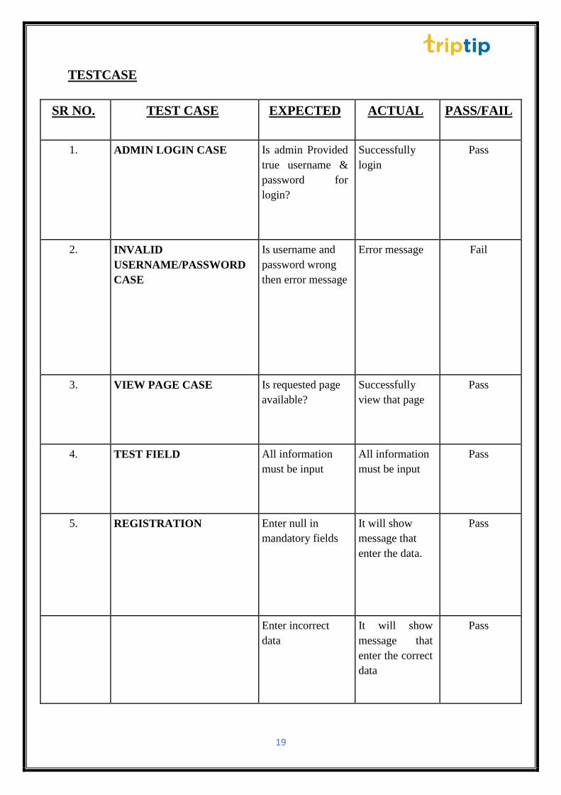
TESTCASE
SR NO. TEST CASE EXPECTED ACTUAL PASS/FAIL
1. ADMIN LOGIN CASE Is admin Provided
true username &
password for
login?
Successfully
login
Pass
2. INVALID
USERNAME/PASSWORD
CASE
Is username and
password wrong
then error message
Error message Fail
3. VIEW PAGE CASE Is requested page
available?
Successfully
view that page
Pass
4. TEST FIELD All information
must be input
All information
must be input
Pass
5. REGISTRATION Enter null in
mandatory fields
It will show
message that
enter the data.
Pass
Enter incorrect
data
It will show
message that
enter the correct
data
Pass

20
SR NO. TEST CASE EXPECTED ACTUAL PASS/FAIL
6. USER LOGIN CASE Is User provided
true user name
& password for
login?
Successfully
login
Pass
7. INVALID
USERNAME/PASSWORD
CASE
Is username and
password wrong
then error
message
Error message Fail
8. VIEW PAGE CASE Is requested
page available?
Successfully
view that page
Pass
9. VALIDATION TEST
CASES
Mandatory field
should not be
blank
You have to
enter some
value into
mandatory
fields
Pass
The field value
must have the
predefined
range
Only 10
number are
enter in the
field
Pass
A predefines
format should
be follow
Check the
proper format
of email-id
Pass
10. MANAGE PROFILE User can edit
info of the
profile
The Message
will be
displayed
“Profile edit
successfully”.
Pass

21