design, deployment and management of unified wlan€¦ · design, deployment and management of...
TRANSCRIPT

Design, Deployment
and Management of
Unified WLAN

Understanding WLAN Controllers 1st/2nd Generation vs. 3rd Generation Approach
• 1st/2nd generation: APs act as
802.1Q translational bridge, putting
client traffic on local VLANs
• 3rd generation: Controller bridges
client traffic centrally
1st/2nd Generation
Data VLAN
Voice VLAN
Management VLAN
3rd Generation Data VLAN
Voice VLAN
Management VLAN
LWAPP/CAPWAP
Tunnel

Centralized Wireless LAN Architecture What Is CAPWAP?
• CAPWAP: Control and Provisioning of Wireless Access Points
• Used between APs and WLAN controller and based on LWAPP
• CAPWAP carries control and data traffic between the two – Control plane is DTLS encrypted
– Data plane is DTLS encrypted (optional)
• LWAPP-enabled access points can discover and join a CAPWAP controller,
and conversion to a CAPWAP controller is seamless
CAPWAP Controller
Wi-Fi Client
Business
Application
Control Plane
Data Plane Access
Point

CAPWAP Modes • The CAPWAP protocol supports two modes of operation
– Split MAC (centralized mode)
– Local MAC (FlexConnect/H-REAP)
• Split MAC
WTP AC STA
Wireless Phy
MAC Sublayer
CAPWAP
Data Plane
Wireless Frame
802.3 Frame

CAPWAP Modes • The CAPWAP protocol supports two modes of operation
– Split MAC (centralized mode)
– Local MAC (FlexConnect/H-REAP)
• Locally bridged
WTP AC
Wireless Phy
MAC Sublayer
Wireless Frame
802.3 Frame
STA

Cisco Unified Wireless Principles
• Components
• Wireless LAN controllers
• Aironet access points
• Management System (NCS)
• Mobility Service Engine
(MSE)
• Principles
• AP must have CAPWAP
connectivity with WLC
• Configuration
downloaded to AP by WLC
• All Wi-Fi traffic is
forwarded to the WLC
Wireless LAN
Controllers
Aironet
Access Point
NCS
MSE
Campus
Network

Controller Redundancy Dynamic
• Rely on CAPWAP to load-balance APs across controllers and populate APs
with backup controllers
• Results in dynamic ―salt-and-pepper‖ design
• Pros
– Easy to deploy and configure—less upfront work
– APs dynamically load-balance (though never perfectly)
• Cons
– More intercontroller roaming
– Bigger operational challenges due to unpredictability
– No ―fallback‖ option in the event of controller failure
• Cisco’s general recommendation is:
Only for Layer 2 roaming
• Use deterministic redundancy instead of dynamic redundancy

Controller Redundancy Deterministic
• Administrator statically assigns APs a
primary, secondary, and/or tertiary
controller
– Assigned from controller interface (per AP) or
WCS (template-based)
• Pros
– Predictability—easier operational management
– More flexible and powerful redundancy design
options
– ―Fallback‖ option in the case of failover
• Con
– More upfront planning and configuration
• This is Cisco’s recommended best
practice
WLAN-Controller-A WLAN-Controller-B WLAN-Controller-C
Primary: WLAN-Controller-A Secondary: WLAN-Controller-B Tertiary: WLAN-Controller-C
Primary: WLAN-Controller-B Secondary: WLAN-Controller-C Tertiary: WLAN-Controller-A
Primary: WLAN-Controller-C Secondary: WLAN-Controller-A Tertiary: WLAN-Controller-B

Controller Redundancy Architecture Resiliency
Resiliency N:1 Redundancy
N:N Redundancy N:N:1 Redundancy
WLAN-Controller-A WLAN-Controller-B WLAN-Controller-C
Primary: WLAN-Controller-A Secondary: WLAN-Controller-B Tertiary: WLAN-Controller-C
Primary: WLAN-Controller-B Secondary: WLAN-Controller-C Tertiary: WLAN-Controller-A
Primary: WLAN-Controller-C Secondary: WLAN-Controller-A Tertiary: WLAN-Controller-B
WLAN-Controller-1
WLAN-Controller-2
WLAN-Controller-n
APs Configured With: Primary: WLAN-Controller-1 Secondary: WLAN-Controller-BKP
APs Configured With: Primary: WLAN-Controller-2 Secondary: WLAN-Controller-BKP
APs Configured With: Primary: WLAN-Controller-n Secondary: WLAN-Controller-BKP
WLAN-Controller-BKP NOC or Data Center
WLAN-Controller-A
WLAN-Controller-B
APs Configured With: Primary: WLAN-Controller-A Secondary: WLAN-Controller-B Tertiary: WLAN-Controller-BKP
APs Configured With: Primary: WLAN-Controller-B Secondary: WLAN-Controller-A Tertiary: WLAN-Controller-BKP
WLAN-Controller-BKP NOC or Data Center
WLAN-Controller-A
WLAN-Controller-B
APs Configured With: Primary: WLAN-Controller-A Secondary: WLAN-Controller-B
APs Configured With: Primary: WLAN-Controller-B Secondary: WLAN-Controller-A

AP-Grouping in Campus
Data Center WAN Internet
Access
Distribution
Core
Distribution
Access
SiSi SiSi SiSi SiSi SiSi SiSi
SiSi SiSi
SiSi SiSi
SiSi SiSi
SiSi SiSi
WLC-2 WLC-1
VLAN 100 / 21
CAPWAP
Single SSID =
Employee
VLAN 100 VLAN 100 VLAN 100

AP-Grouping in Campus
Data Center WAN Internet
Access
Distribution
Core
Distribution
Access
SiSi SiSi SiSi SiSi SiSi SiSi
SiSi SiSi
SiSi SiSi
SiSi SiSi
SiSi SiSi
AP-Group-2 AP-Group-3 AP-Group-1
WLC-2 WLC-1
VLAN 80 /23 VLAN 70 /23 VLAN 60 /23
CAPWAP
VLAN 60
VLAN 70
VLAN 80
Single SSID =
Employee

Interface-Grouping in Campus
Data Center WAN Internet
Access
Distribution
Core
Distribution
Access
SiSi SiSi SiSi SiSi SiSi SiSi
SiSi SiSi
SiSi SiSi
SiSi SiSi
SiSi SiSi
WLC-2 WLC-1
CAPWAP
VLAN 60
VLAN 61
VLAN 62
VLAN 63
VLAN 64
VLAN 65
Single SSID =
Employee

Scaling the Architecture with Mobility Groups
• Mobility Group allows controllers to peer with each other to support seamless
roaming across controller boundaries
• APs learn the IPs of the other members of the mobility group after the LWAPP
Join process
• Support for up to 24 controllers,
24,000 APs per mobility group
• Mobility messages exchanged
between controllers
(Multicast)
• Data tunneled between
controllers in EtherIP
(RFC 3378)
Eth
ern
et in
IP
Tu
nn
el
Mobility Messages
Controller-C MAC: AA:AA:AA:AA:AA:03 Mobility Group Name: MyMobilityGroup Mobility Group Neighbors: Controller-A, AA:AA:AA:AA:AA:01 Controller-B, AA:AA:AA:AA:AA:02
Controller-A MAC: AA:AA:AA:AA:AA:01 Mobility Group Name: MyMobilityGroup Mobility Group Neighbors: Controller-B, AA:AA:AA:AA:AA:02 Controller-C, AA:AA:AA:AA:AA:03
Controller-B MAC: AA:AA:AA:AA:AA:02 Mobility Group Name: MyMobilityGroup Mobility Group Neighbors: Controller-A, AA:AA:AA:AA:AA:01 Controller-C, AA:AA:AA:AA:AA:03

Increased Mobility Scalability
• Roaming is supported across three mobility groups
(3 * 24 = 72 controllers)
• With Inter Release Controller Mobility (IRCM) roaming is supported between
4.2.207 and 6.0.188 and 7.0
Eth
ern
et in
IP
Tunnel Mobility Sub-Domain 2
Eth
ern
et in
IP
Tunnel Mobility Sub-Domain 1
Eth
ern
et in
IP
Tunnel Mobility Sub-Domain 3
Mobility Messages

Inter-Controller Roaming: Layer 2
WLC-1 WLC-2
WLC-1 Client
Database
WLC-2 Client
Database
Mobility Message Exchange
Preroaming
Data Path
Client Data (MAC,
IP, QoS, Security)
VLAN X
Inter-Controller roam happens when a client moves association between APs joined to different controller
Client must be re-authenticated and new security session established

Inter-Controller Roaming: Layer 2
WLC-1 WLC-2
WLC-1 Client
Database
WLC-2 Client
Database
Mobility Message Exchange
Preroaming
Data Path
Client Data (MAC,
IP, QoS, Security)
VLAN X
Client database entry with new AP and appropriate security context
No IP address refresh needed
Client Roams to a
Different AP

Inter-Controller Roaming: Layer 3
WLC-1 WLC-2
WLC-1 Client
Database
WLC-2 Client
Database
Mobility Message Exchange
VLAN X
Client Data (MAC, IP,
QoS, Security) Client Data (MAC,
IP, QoS, Security)
VLAN Z
• Client must be re-authenticated and new security session established
• Client database entry copied to new controller – entry exists in both
WLC client DBs
• Original controller tagged as the ―anchor‖, new controller tagged as the
―foreign‖
• WLCs must be in same mobility group or domain

Inter-Controller Roaming: Layer 3
WLC-1 WLC-2
WLC-1 Client
Database
WLC-2 Client
Database
Mobility Message Exchange
VLAN X
Client Data (MAC, IP,
QoS, Security) Client Data (MAC,
IP, QoS, Security)
VLAN Z
Client Roams to a
Different AP
Foreign
Controller
Anchor
Controller
• No IP address refresh needed
• Symmetric traffic path established
• Account for mobility message exchange in network design

Designing a Mobility Group/Domain
Design Considerations
• Less roaming is better – clients and apps are happier
• L3 roaming & fast roaming clients consume client DB slots on multiple
controllers – consider ―worst case‖ scenarios in designing roaming
domain size
• Leverage natural roaming domain boundaries
• Mobility Message transport selection: multicast vs. unicast
• Make sure the right ports and protocols are allowed

Branch Designs Using Remote Controllers
• Branches can also have local remote
controllers
• Small form factors WLC are
available to have « small campus »:
WLC-2504 or Integrated controller
modules in ISR/ISR-G2
• High Availability design with
central backup controller is
supported. WAN limitations
may apply.
WAN
Central Site
Remote Site B Remote Site A
Backup Central
Controller
WLC-21xx WLCM for
ISR/ISR-G2

WAN/MAN
Branch Office Deployment
FlexConnect • Hybrid Remote Edge Access
Point architecture (H-REAP)
• Single management and control
point
• Data Traffic Switching
– Centralized traffic
or
– Local traffic
• Traffic Switching is configured
per AP and per WLAN (SSID)
Central Site
Store Manufacturing Plan
AP Group 2
AP Group 3
AP Group 1
Corporate-Voice
Guest-Access
Corporate-Data
Guest-Access
Corporate-Data
@ Internet
Scanners

FlexConnect – Advanced Services
• High Availability – WAN Survivability
– FlexConnect AP provides wireless access and services to clients when the
connection to the primary WLC fails
• Local Authentication
– Allows for the authentication capability to exist directly at the AP in
FlexConnect instead of the WLC
• Fast roaming in remote branches
• Dynamic VLAN assignment
• Scalability
– Number of FlexConnect groups: 500 (7500s) and 100 (5500s)
– APs per Group: 50 (7500s) and 25 (5500s)

FlexConnect – WLC Authenticator
Branch Office Data Center
WLC
ISR 3925 ISR 3925
VPN
AP
ISR 3925 ISR 3925
Dot1X Auth Req
Dot1x Auth Success
New Client 1
2
AAA RADIUS
• All the client authentication requests travels through Central Controller
• If Controller is not reachable, then no clients can authenticate

FlexConnect – AP Authenticator
Branch Office Data Center
WLC
ISR 3925 ISR 3925
VPN
AP
ISR 3925 ISR 3925
Dot1X Auth Req
Dot1x Auth Success
New Client
• All the client authentication requests travels straight from AP to RADIUS Server.
• If Controller is not reachable, clients can still continue to authenticate and
access network services.
1
2
AAA RADIUS

FlexConnect – AP Authenticator
Branch Office Data Center
WLC
ISR 3925 ISR 3925
AP
ISR 3925 ISR 3925
Dot1X Auth Req
Dot1x Auth
Success
New Client
• All the client authentication requests travels straight from AP to Local Branch
RADIUS Server.
• If WAN link is down, clients can still continue to authenticate and access network
services.
1
2
AAA RADIUS

Local Authentication – AP as EAP Server
Branch Office Data Center
WLC
ISR 3925 ISR 3925
AP
ISR 3925 ISR 3925 Dot1X Auth Req
Dot1x Auth
Success
• All the client authenticated directly by the AP.
• If WAN link & Local Backup RADIUS Server is down clients can still continue to
authenticate and access network services.
1
2
AAA RADIUS

H-REAP Design Considerations
• Some WAN limitations apply
– RTT must be below 300 ms data (100 ms voice)
– Minimum 500 bytes WAN MTU (with maximum four fragmented
packets)
• Some features are not available in standalone mode or in
local switching mode
– See full list in « H-REAP Feature Matrix »
http://www.cisco.com/en/US/products/ps6366/products_tech_note091
86a0080b3690b.shtml

Headquarters
Internet VPN
MPLS
ATM
Frame Relay
Home Office Design – OEAP
• Cisco controller installed in the DMZ of the corporate
network
• OfficeExtend AP (OEAP) installed at teleworker’s
home
• Corporate access to employee over centrally
configured SSID
• Family Internet access over a locally configured SSID
WLC 5508 / WiSM-2
NCS

Cisco Unified Wireless Network Flexible, Resilient, Scalable Architecture
Access
Network
Distribution
Network
Teleworker/S
OHO
OfficeExtend AP
Branch Office
Unified WLC Options:
5508, 440x, 210x
3750G Unified WLC
WLCM Module
Hybrid REAP
Standalone AP
DMZ Guest Controller
440x, 5508 WLC
Network Core or Data Center
Centralized WLC Design 440x, 5508 WLC, WiSM Unified WLC
Distributed WLC Design 440x, 5508 WLC,
WiSM Unified WLC
Highly Distributed Design
3750G Unified WLC
Enterprise Hybrid REAP
Data Center
Internet
Internet
Unified
Outdoor/Indoor
Access
Unified Management: Wireless Control System
Services Platform: Mobility Services Engine

Campus and
Full Service Branch
2500
WLCM2
5500 WiSM2
Scale
Fe
atu
res / P
erf
orm
ance
7500
Cisco WLAN Controller Portfolio

802.11n WiFi
Business-Ready Mission Critical Best in Class
Mission Critical
Cisco Aironet 802.11n Access Points Teleworker
AP 3600
With CleanAir
technology
AP 3500
AP 1260
AP 1140 AP 1040
OfficeExtend
AP 600

But Dual Stack
Clients Are Here
Now…
IPv6 Will Be a Phased Implementation

Wireless IPv6 Client Support
• Supports IPv4, Dual Stack and Native IPv6 clients on single WLAN simultaneously.
• Supports the following IPv6 address assignment for wireless clients:
IPv6 Stateless Autoconfiguration [SLAAC]
Stateless, Stateful DHCPv6
Static IPv6 configuration
• Supports up to 8 IPv6 addresses per client.
• Clients will be able to pass traffic once IPv4 and/or IPv6 address assignment is completed after successful authentication.
CAPWAP IPv4
IPv6
Ethernet VLAN
Ethernet
IPv6
CAPWAP Tunnel
IPv4 802.11
IPv4
IPv4 IPv6 802.11
IPv6 802.11

Many IPv6 Addresses Per Client
• Support for many IPv6 addresses per client is necessary because: Clients can have multiple address types per interface
Clients can be assigned addresses via multiple methods such as SLAAC and DHCPv6
Most clients automatically generate a temporary address in addition to assigned addresses.
Up to 8 IPv6 Addresses
are Tracked per Client.

Complete IPv6 Support
• First Hop Security & Optimization
– DHCPv6 Server Guard
– Router Advertisement (RA) Guard
– IPv6 Source Guard
– Neighbor Solicitation (NS) Suppression
– Router Advertisement (RA) Throttling
• Layer 2 & 3 Roaming
• IPv6 ACL support
• QoS support
• Guest access support
• Multicast to Unicast conversion at the AP
• FlexConnect
#CiscoPlusCA
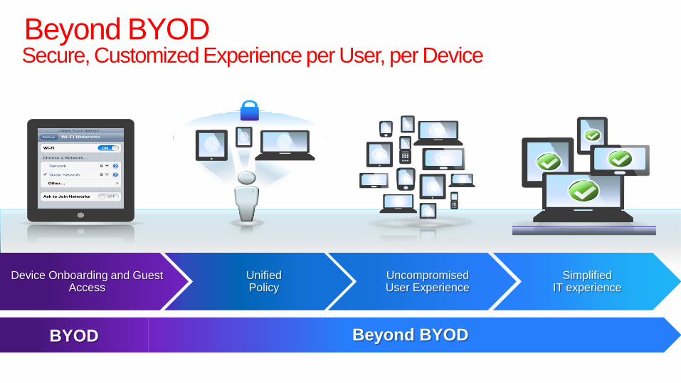
Beyond BYOD
BYOD Beyond BYOD
Device Onboarding and Guest Access
Unified Policy
Uncompromised User Experience
Simplified IT experience
Secure, Customized Experience per User, per Device

Internet
Email, Calendar
Regulated data
(finance, personal info)
Control Govern access to
resources based on
scenario
2
Connect
1 Securing Any
Access
3
Manage Visibility into user
experience across
wired and wireless
Managing
Complexity
And Scale
Optimize Accelerate and protect
performance for
applications
4
Delivering High-
Quality
Experience
Cisco BYOD+

Cisco BYOD+ IT Challenges to Mobile Freedom

3600 Access Point Industry's only 4x4: 3 spatial stream access point
• Deliver 30% more performance
• Deliver mission critical reliability
with CleanAir
• Boost client performance with
ClientLink 2.0
• Add-on modules with the
Modular architecture

Triple-Stream Video Capacity
With a mix of all types of video clients using multicast and unicast TCP video (AirVideo), Cisco delivers 3x the performance.
210% Better
1 Mbps
Stream
2 Mbps
Stream
5 Mbps
Stream
Competitor Cisco 3600

Cisco Identity Services Engine – ISE
Real-Time Awareness Track Active Users and Devices
Keep Existing Logical Design
Manage Security Group Access
SGT Public Private
Staff
Guest
Permit
Deny
Permit
Permit
Profiling of wired and wireless devices
Integrated and built into ISE policy LOCATION USER ID ACCESS
RIGHTS DEVICE (& IP/MAC)
Consolidated Contextual Information Integrated Device Profiling &
Posture Assessment
Simplified Role-Based Access
Consistent Policy for Device Categories
System-wide Visibility
Troubleshoot and Monitoring
Consolidated Data
Guest Lifecycle Management
Provide Guest Access in a seamless,
secure manner
Scales to meet organizations needs
Scalable Architecture Innovative Licensing

Policy Profiling
VLAN 10 VLAN 20
Personal
Employee
Corporate
Wireless LAN
Controller
Corporate
Resources
Restricted
Internet Only
USER LOCATION
TIME ATTRIBUTE X
DNS
RADIUS SNMP
NETFLOW
District Issued Device
1. 802.1x EAP User Authentication
2. Profiling to identify device
3. Policy decision
4. Policy enforce to ―VLAN 10‖ on same SSID
5. Full access granted
6. Full device visibility
PERSONAL Device
1. 802.1x EAP User Authentication
2. Profiling to identify device
3. Policy decision
4. Policy enforce to ―VLAN 10 or 20‖ on same SSID
5. Full or Restricted access granted
6. Full device visibility
HTTP
DHCP DEVICE
Centralized
Policy Engine
Unified Access
Management
Single SSID
Cisco's Borderless - Unified Policy Management

On-Boarding (1.1MR June 12)
Supplicant profile provisioning on supported platforms (iOS, Android, Windows, OS X)
Self / Sponsor registration portals for users and devices
Secure access (single SSID, certificate based differentiation of service)
Certificate provisioning as registry authority (RA) adding username and device ID to cert (integrates with existing corp CA/PKI)
User initiated control their devices (designate “Lost” -> black-listing, re-instate device, etc)

On Prem MDM Device Registration - non registered clients redirected to MDM registration page
Restricted Access - non compliant clients will be given restricted access based on MDM posture state
Ability initiate device action from ISE - eg: device stolen -> need to wipe data on client (Stretch).
Augment Endpoint Data - Update data from endpoint which cannot be gathered by profiling
MDM Integration (ISE 1.2 Fall 2012)

0
50
100
150
200
250
300
350
400
Client devices (Drivers,
connections, authentication, or other issues)
RF Interference from Wi-Fi
and/or non-Wi-Fi sources
Unexpected demand for increased
converage of capacity
Faulty wireless network design implementation
Old or outdated wireless
technology
Insufficient IT adminstrator
expertise
Other
Nu
mb
er
of
Cu
sto
mers
Contributors to Wireless Network Problems
A recent survey shows that respondents view client devices as the top
contributor to BYOD Wireless network performance problems
Cisco's Unified Network Management Top BYOD Wireless Issues

Cisco Prime Network Control System Converged Access Management for Wired and Wireless Networks
• Flexible platform: Accommodates new and experienced IT administrators
• Simple, intuitive user interface: Eliminates complexity
• User-defined customization: Display the most relevant information
High-Level View of Key Metrics with Contextual Drill-Down to Detailed Data

Integrated Access Infrastructure Visibility • Wired and wireless discovery and
inventory
Add/detect infrastructure devices such as switches, WLAN controllers, and access points
• Comprehensive access infrastructure reporting
View the access infrastructure as a whole
• Stolen asset notification
Track when devices presumed stolen come back online

Unified User and Endpoint Services
• Correlated and focused wired/wireless client visibility
Client health metrics
Client posture and profile
Client troubleshooting
Client reporting
Unknown device ID input
• Clear view of the end user landscape
Who is connecting
Using which device
Are they authorized
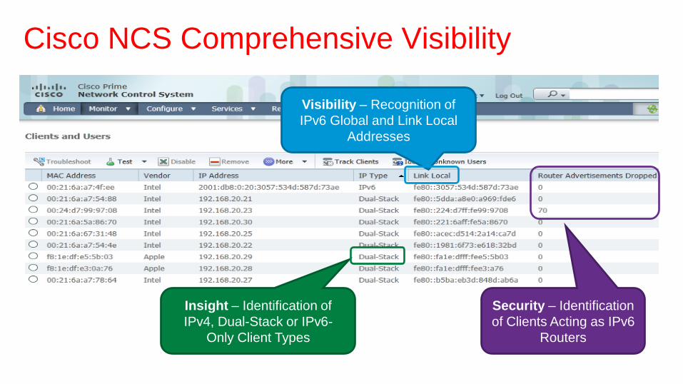
Cisco NCS Comprehensive Visibility
Security – Identification
of Clients Acting as IPv6
Routers
Insight – Identification of
IPv4, Dual-Stack or IPv6-
Only Client Types
Visibility – Recognition of
IPv6 Global and Link Local
Addresses

Troubleshoot Wired and Wireless Access Using Cisco Prime for Converged Client Devices
1. Search on user name
2. Identify wired and wireless devices
associated with the user
3. Display associated and disassociated
devices
4. Use automated client troubleshooting
workflow to resolve the issue
5. Issue resolved
USE CASE: User calls in to help center because they cannot get access to financial data on the network. IT determines if they are authorized to access this area.
Troubleshoot user and access issues based on identity
Speed resolution with intuitive guided workflows
Cisco Prime Network Control System (NCS)
Step by Step Recommendations

The Cisco Advantage A Better Mobility Experience for Users and IT

Q&A
#CiscoPlusCA
Follow @CiscoCanada and join the #CiscoPlusCA conversation
Access today’s presentations at cisco.com/ca/plus
We value your feedback. Please be sure to complete the Evaluation Form for this session.