design ez easy-e control valve - stickle steam - 100 years ... · pdf filedesign ez easy-e...
TRANSCRIPT

www.Fisher.com
D10
0401
X01
2
Design EZ easy-e� Control ValveContents
Introduction 1. . . . . . . . . . . . . . . . . . . . . . . . . . . . . . . Scope of Manual 1. . . . . . . . . . . . . . . . . . . . . . . . . Description 1. . . . . . . . . . . . . . . . . . . . . . . . . . . . . . Specifications 2. . . . . . . . . . . . . . . . . . . . . . . . . . . .
Installation 2. . . . . . . . . . . . . . . . . . . . . . . . . . . . . . . . Maintenance 3. . . . . . . . . . . . . . . . . . . . . . . . . . . . . .
Packing Lubrication 5. . . . . . . . . . . . . . . . . . . . . . . Packing Maintenance 5. . . . . . . . . . . . . . . . . . . . .
Replacing Packing 8. . . . . . . . . . . . . . . . . . . . . . . Trim Maintenance 10. . . . . . . . . . . . . . . . . . . . . . .
Disassembly 10. . . . . . . . . . . . . . . . . . . . . . . . . . . Lapping Metal Seats on Valves with Plain
and Extension Bonnets 12. . . . . . . . . . . . . . . Assembly 12. . . . . . . . . . . . . . . . . . . . . . . . . . . . . .
ENVIRO-SEAL� Bellows Seal and Bonnet 15. . Replacing a Plain or Extension Bonnet
with an ENVIRO-SEAL Bellows Seal(Stem/Bellows Assembly) and Bonnet 15. .
Replacing an Installed ENVIRO-SEALBellows Seal (Stem/Bellows Assembly) 17.
Purging the ENVIRO-SEALBellows Seal Bonnet 18. . . . . . . . . . . . . . . . .
Parts Ordering 18. . . . . . . . . . . . . . . . . . . . . . . . . . . . Parts Kits 19. . . . . . . . . . . . . . . . . . . . . . . . . . . . . . . . Parts List 20. . . . . . . . . . . . . . . . . . . . . . . . . . . . . . . .
Introduction
Scope of ManualThis instruction manual includes installation,maintenance, and parts information for 0.5- through4-inch Design EZ valves through Class 600 ratings.Refer to separate manuals for instructions coveringthe actuator and accessories.
No person may install, operate, or maintain a DesignEZ valve without first � being fully trained andqualified in valve, actuator, and accessoryinstallation, operation, and maintenance, and �carefully reading and understanding the contents ofthis manual. If you have any questions about theseinstructions, contact your Fisher� sales office beforeproceeding.
W8120A-1
Figure 1. Design EZ Valve with Type 657 Actuator andDVC6000 Digital Valve Controller
DescriptionDesign EZ valves (figure 1) are globe-style withintegral end connections, post guiding, andquick-change trim. These valves are used inchemical or hydrocarbon processing applications orin applications that require control of nonlubricating,viscous, or other hard-to-handle fluids.
Note
Neither Emerson�, Emerson ProcessManagement, nor Fisher assumeresponsibility for the selection, use, ormaintenance of any product.Responsibility for proper selection,use, and maintenance of any Fisherproduct remains solely with thepurchaser and end-user.
Instruction ManualForm 5118April 2005 EZ Valve

EZ ValveInstruction Manual
Form 5118April 2005
2
Table 1. Specifications
End Connection Styles
Cast Iron ValvesFlanged: Class 125 flat-face or 250 raised-faceflanges per ASME B16.1Screwed: Consistent with ASME B16.4Steel and Stainless Steel ValvesFlanged: Class 150, 300, and 600 raised-face orring-type joint flanges per ASME B16.5Screwed or Socket Welding: Consistent withASME B16.11Buttwelding: All available ASME B16.25schedules that are consistent with ASME B16.34
Maximum Inlet Pressure(1)
Cast Iron ValvesFlanged: Consistent with Class 125B or 250B perASME B16.1Screwed: Consistent with Class 250 per ASMEB16.4Steel and Stainless Steel ValvesFlanged: Consistent with Class 150, 300, or 600per ASME B16.34
Screwed or Welding: Consistent with Class 600per ASME B16.34
Shutoff Classifications per ANSI/FCI 70-2and IEC 60534-4
Metal Seats: Class IV is standard, Class V isoptionalPTFE Composition Seats: Class VI
Flow Characteristics
� Equal percentage, � quick opening, and� linear
Flow Direction
Up through the seat ring
Approximate Weights
0.5 and 0.75-Inch Valves: 9.1 kg (20 pounds)1-Inch Valve: 11 kg (25 pounds)1.5 Inch Valve: 18 kg (40 pounds)2-Inch Valve: 36 kg (80 pounds)3-Inch Valve: 54 kg (120 pounds)4-Inch Valve: 75 kg (165 pounds)
1. The pressure/temperature limits in this manual and any applicable standard or code limitation for valve should not be exceeded.
SpecificationsTypical specifications for these valves are shown intable 1.
Installation
WARNING
Always wear protective gloves,clothing, and eyewear whenperforming any installation operationsto avoid personal injury.
Personal injury or equipment damagecaused by sudden release of pressuremay result if the valve assembly isinstalled where service conditionscould exceed the limits given in table 1or on the appropriate nameplates. Toavoid such injury or damage, provide arelief valve for overpressure protection
as required by government oraccepted industry codes and goodengineering practices.
Check with your process or safetyengineer for any additional measuresthat must be taken to protect againstprocess media.
If installing into an existingapplication, also refer to the WARNINGat the beginning of the Maintenancesection in this instruction manual.
CAUTION
When ordered, the valve configurationand construction materials wereselected to meet particular pressure,temperature, pressure drop, andcontrolled fluid conditions.Responsibility for the safety ofprocess media and compatibility ofvalve materials with process mediarests solely with the purchaser andend-user. Since some body/trim

EZ ValveInstruction ManualForm 5118April 2005
3
Figure 2. Optional Packing Lubricator andLubricator/Isolating Valve
���������
���������������� ������10A9421-AAJ5428-DA0832-2/IL
material combinations are limited intheir pressure drop and temperatureranges, do not apply any otherconditions to the valve without firstcontacting your Fisher sales office.
1. Before installing the valve, inspect it and anyassociated equipment for damage and any foreignmaterial. Make certain the valve interior is clean, thatpipelines are free of foreign material, and that thevalve is oriented so that pipeline flow is in the samedirection as the arrow on the side of the valve.
2. The control valve assembly may be installed inany orientation unless limited by seismic criteria.However, the normal method is with the actuatorvertical above the valve. Other positions may resultin uneven valve plug and seat ring retainer wear,and improper operation. With some valves, theactuator may also need to be supported when it isnot vertical. For more information, consult yourFisher sales office.
3. Use accepted piping and welding practices wheninstalling the valve in the line. Internal elastomericparts may stay in place during the weldingprocedure. For flanged valves, use a suitable gasketbetween the valve body flange and pipeline flanges.
Note
Depending on valve body materialsused, post weld heat treating may berequired. If so, damage to internalelastomeric and plastic parts, as wellas internal metal parts is possible.Shrunk-fit pieces and threaded
connections may also loosen. Ingeneral, if post weld heat treating is tobe performed, all trim parts should beremoved. Contact your Fisher salesoffice for additional information.
4. With a leak-off bonnet construction, remove thepipe plugs (key 14) to hook up the leak-off piping. Ifcontinuous operation is required during inspection ormaintenance, install a three-valve bypass around thecontrol valve assembly.
5. If the actuator and valve are shipped separately,refer to the actuator mounting procedure in theappropriate actuator instruction manual.
WARNING
Personal injury could result frompacking leakage. Valve packing wastightened before shipment; however,the packing might require somereadjustment to meet specific serviceconditions. Check with your processor safety engineer for any additionalmeasures that must be taken toprotect against process media.
Valves with ENVIRO-SEAL� live-loaded packing orHIGH-SEAL� Heavy-Duty live-loaded packing willnot require this initial re-adjustment. See the Fisherinstruction manuals titled ENVIRO-SEAL PackingSystem for Sliding-Stem Valves or Heavy-DutyLive-Loaded Packing System (as appropriate) forpacking instructions. If you wish to convert yourpresent packing arrangement to ENVIRO-SEALpacking, refer to the retrofit kits listed in the PartsKits sub-section near the end of this manual.
MaintenanceValve parts are subject to normal wear and must beinspected and replaced as necessary. Inspectionand maintenance frequency depends on the severityof service conditions. This section includesinstructions for packing lubrication, packingmaintenance, trim maintenance, and ENVIRO-SEALbellows seal replacement. All maintenanceoperations may be performed with the valve in theline.
WARNING
Avoid personal injury or propertydamage from sudden release of

EZ ValveInstruction Manual
Form 5118April 2005
4
Figure 3. PTFE V-Ring Packing Arrangements for Plain and Extension Bonnets
12A37837-AB1429-5*/IL
B1428-5*
��������������������� ���������������������� ����������������������
process pressure or bursting of parts.Before performing any maintenanceoperations:
� Always wear protective gloves,clothing, and eyewear whenperforming any maintenanceoperations to avoid personal injury.
� Disconnect any operating linesproviding air pressure, electric power,or a control signal to the actuator. Besure the actuator cannot suddenlyopen or close the valve.
� Use bypass valves or completelyshut off the process to isolate thevalve from process pressure. Relieveprocess pressure from both sides ofthe valve. Drain the process mediafrom both sides of the valve.
� Vent the pneumatic actuatorloading pressure and relieve anyactuator spring precompression.
� Use lock-out procedures to besure that the above measures stay ineffect while you work on theequipment.

EZ ValveInstruction ManualForm 5118April 2005
5
Figure 4. PTFE/Composition Packing Arrangements for Plain and Extension Bonnets
B0968-1*/IL
12A8188-A 12A7815-A 12A8173-A
��������������������� ���������������������� ����������������������
� The valve packing box maycontain process fluids that arepressurized, even when the valve hasbeen removed from the pipeline.Process fluids may spray out underpressure when removing the packinghardware or packing rings, or whenloosening the packing box pipe plug.
� Check with your process or safetyengineer for any additional measuresthat must be taken to protect againstprocess media.
Note
Whenever a gasket seal is disturbedby removing or shifting gasketedparts, a new gasket should be installedupon reassembly. This is necessary toensure a good gasket seal since theused gasket may not seal properly.
Note
If the valve has ENVIRO-SEAL orHIGH-SEAL live-loaded packinginstalled, refer to instruction manualsENVIRO-SEAL Packing System forSliding Stem Valves, Form 5306, orHIGH-SEAL Live Loaded Packing
System, Form 5263, for packinginstructions. Figure 6 shows a typicalHIGH-SEAL packing system. Figures 7and 8 show typical ENVIRO-SEALsystems.
Packing LubricationNote
ENVIRO-SEAL or HIGH-SEAL packingdoes not require lubrication.
If an optional lubricator or lubricator/isolating valve(figure 2) is provided for PTFE/composition or otherpackings that require lubrication, it will be installed inan optional tapped hole in the bonnet. Use a goodquality silicon-base lubricant. Packing used inoxygen service or in processes with temperaturesover 260�C (500�F) should not be lubricated. Tooperate the lubricator, simply turn the cap screwclockwise to force the lubricant into the packing box.The lubricator/isolating valve must first be openedand then closed after lubrication is completed.
Packing MaintenanceThis section covers PTFE V-ring, PTFE/composition,and graphite/ribbon packing as used in plain andextension bonnets. Unless otherwise indicated, keynumbers refer to figure 3 for PTFE V-ring packing,figure 4 for PTFE/composition packing, and figure 5for graphite ribbon/filament packing.

EZ ValveInstruction Manual
Form 5118April 2005
6
Figure 5. Graphite Ribbon/Filament Packing Arrangements for Plain and Extension Bonnets
NOTE: 0.102 mm (0.004 INCH) THICK SACRIFICIAL ZINC WASHERS:USE ONLY ONE BELOW EACH GRAPHITE RIBBON RING.1
A5514-2/IL
A5513-2/IL
�������������������
��������������������
��������������������
��������������������
��������������������
�������������������
For spring-loaded single PTFE V-ring packing, thespring (key 8, figure 3) maintains a sealing force onthe packing. If leakage is noted around the packingfollower (key 13, figure 3), check to be sure theshoulder on the packing follower is touching thebonnet. If the shoulder is not touching the bonnet,tighten the packing flange nuts (key 5, figure 11),until the shoulder is against the bonnet. If leakagecannot be stopped in this manner, proceed to theReplacing Packing procedure.
If there is unacceptable packing leakage with otherthan spring-loaded packing, first try to limit theleakage and establish a stem seal by tightening thepacking flange nuts.
If the packing is relatively new and tight on the stem,and if tightening the packing flange nuts does notstop the leakage, the valve stem may be worn ornicked so that a seal cannot be made. The surfacefinish of a valve stem is critical for making a goodpacking seal. If the leakage comes from the outsidediameter of the packing, the leakage may be causedby nicks or scratches around the packing box wall. Ifperforming any of the following procedures, inspectthe valve stem and packing box wall for nicks andscratches.
An illustration of a HIGH-SEAL live-loaded packingsystem is shown in figure 6. Illustrations ofENVIRO-SEAL live-loaded packing systems areshown in figures 7, 8, and 9.

EZ ValveInstruction ManualForm 5118April 2005
7
Figure 6. Typical HIGH-SEAL Graphite ULFPacking System
39B4153-A
1. FIND NUMBER 219NOT REQUIRED WITH3/8-INCH STEM
Figure 7. Typical ENVIRO-SEAL� Packing System withPTFE Packing
NOTE: FOR PTFE PACKING, TIGHTEN THE PACKING BOX HEX NUTS UNTIL THETOP OF THE FLANGE IS EVEN WITH THE TOP OF THE SLEEVE ON THE FOL-LOWER (SPRING PACK ASSEMBLY).
1
1
A6297/IL
Figure 8. Typical ENVIRO-SEAL Packing System withGraphite ULF Packing
PACKINGRING(KEY 209)
PACKINGRING(KEY 210)
PACKINGBOX RING(KEY 211)
STUD(KEY 200)
SPRINGPACK
ASSEMBLY(KEY 217)
HEX NUT(KEY 212)
PACKINGFLANGE(KEY 201)
GUIDEBUSHING(KEY 207)
PACKINGWASHERS(KEY 214)
GUIDEBUSHING(KEY 208)
39B4612/A
Figure 9. Typical ENVIRO-SEAL� Packing System withDuplex Packing
200
212
201
215
216
207
209
211
217
207
207
207
214
213
24B9310A6722/IL

EZ ValveInstruction Manual
Form 5118April 2005
8
Table 2. Body-to-Bonnet Torque GuidelinesVALVE SIZE, INCHES TORQUES(1)
Bolt Material
Design EZ SA193-B7 SA193-B8M(2)Design EZN�m Lbf�ft N�m Lbf�ft
1 or smaller 129 95 64 47
1.5 or 2 96 71 45 33
3 169 125 88 65
4 271 200 156 1151. Determined from laboratory tests.2. SA193-B8M annealed.
Replacing Packing
WARNING
Observe the warning at the start of theMaintenance section.
This section covers replacing packing used in plainand extension bonnets. PTFE V-ring packing isshown in figure 3, PTFE/composition packing isshown in figure 4, and graphite/ribbon packing isshown in figure 5.
1. Isolate the control valve from the line pressure,release pressure from both sides of the valve body,and drain the process media from both sides of thevalve. If using a power actuator, also shut off allpressure lines to the power actuator, and release allpressure from the actuator. Use lock-out proceduresto be sure that the above measures stay in effectwhile you work on the equipment.
2. Disconnect the operating lines from the actuatorand any leak-off piping from the bonnet. Disconnectthe stem connector and then remove the actuatorfrom the valve by unscrewing the yoke locknut (key15, figure 11).
WARNING
To avoid personal injury or propertydamage caused by uncontrolledmovement of the bonnet, loosen thebonnet by following the instructions inthe next step. Do not remove a stuckbonnet by pulling on it with equipmentthat can stretch or store energy in anyother manner. The sudden release ofstored energy can cause uncontrolledmovement of the bonnet. If the seatring retainer sticks to the bonnet,proceed carefully with bonnet removal.
Note
The following step also providesadditional assurance that the valvebody fluid pressure has been relieved.
3. Hex nuts (key 16, figure 11) attach the bonnet tothe valve. Loosen these nuts or cap screwsapproximately 3 mm (1/8-inch). Then loosen thebody-to-bonnet gasketed joint by either rocking thebonnet or prying between the bonnet and valvebody. Work the prying tool around the bonnet untilthe bonnet loosens.
4. Loosen the packing flange nuts (key 5, figure 11)so that the packing is not tight on the valve stem.Remove any travel indicator parts and stem locknutsfrom the valve stem threads.
CAUTION
Avoid damaging the seating surfacecaused by the valve plug and stemassembly dropping from the bonnetafter being lifted part way out. Whenlifting the bonnet, temporarily install avalve stem locknut on the valve stem.This locknut will prevent the valveplug and stem assembly fromdropping out of the bonnet.
5. Completely remove the cap screws (not shown)or hex nuts (key 16, figure 12) that bolt the bonnetand valve body together and carefully lift the bonnetoff.
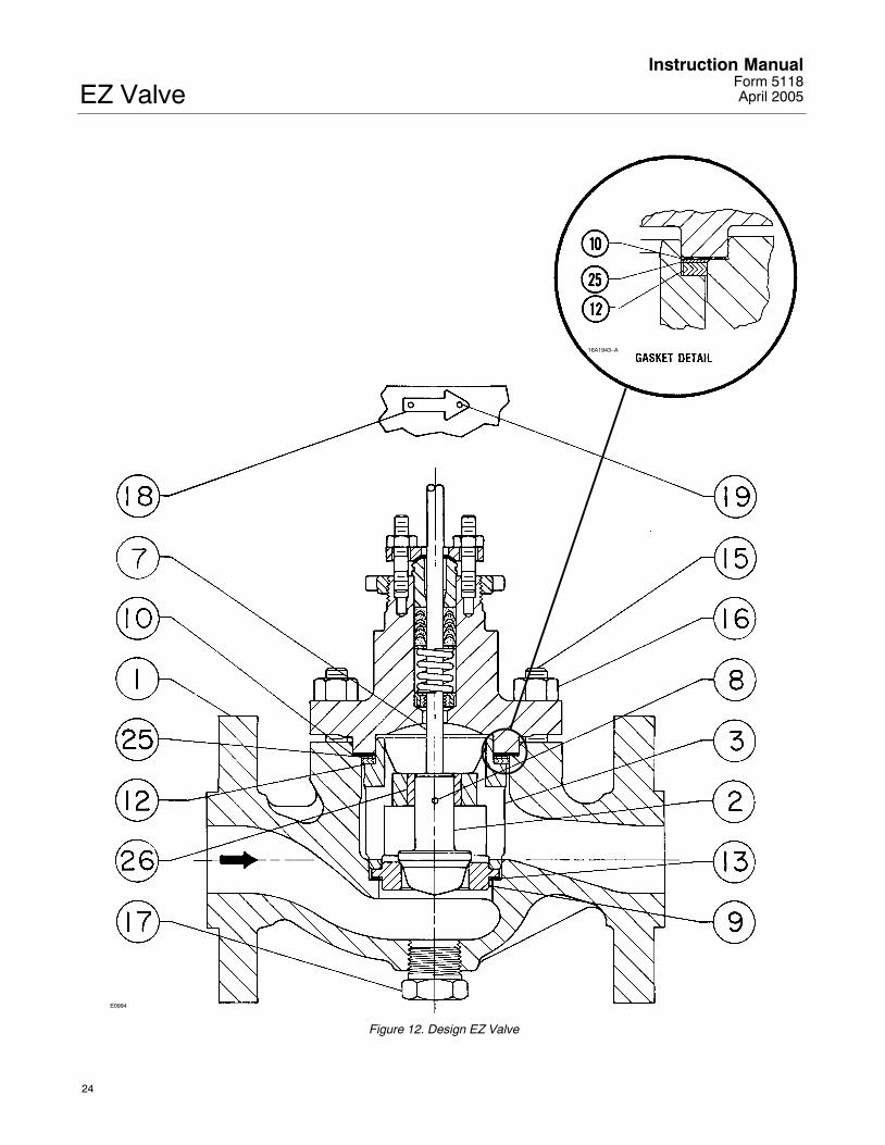
6. Remove the locknut and separate the valve plugand stem from the bonnet. Set the parts on aprotective surface to prevent damage to gasket orseating surfaces.
7. Remove the bonnet gasket (key 10, figure 12)and cover the opening in the valve to protect thegasket surface and to prevent foreign material fromgetting into the valve body cavity.
8. Remove the packing flange nuts, packing flange,upper wiper, and packing follower (keys 5, 3, 12, and
EZ ValveInstruction ManualForm 5118April 2005
9
13, figure 11). Carefully push out all the remainingpacking parts from the valve side of the bonnet usinga rounded rod or other tool that will not scratch thepacking box wall. Clean the packing box and themetal packing parts.
9. Inspect the valve stem threads and the packingbox surfaces for any sharp edges which might cutthe packing. Scratches or burrs could cause packingbox leakage or damage to the new packing. If thesurface condition cannot be improved by lightsanding, replace the damaged parts.
10. Remove the covering protecting the valve cavityand install a new bonnet gasket (key 10, figure 12),making sure the gasket seating surfaces are cleanand smooth. Then slide the bonnet over the stemand onto the stud bolts (key 15, figure 12), or ontothe valve cavity if cap screws (not shown) are usedinstead.
Note
Proper performance of the tighteningprocedures in step 11 compresses thespiral wound gasket (key 12, figure 12)enough to both load and seal the seatring gasket (key 13, figure 12). Thetightening procedures alsocompresses the outer edge of thebonnet gasket (key 10, figure 12)enough to seal the body-to-bonnetjoint.
The accepted bolting proceduresreferred to in step 11 include—but arenot limited to—ensuring that boltingthreads are clean, and evenlytightening the cap screws, or the nutsonto the studs, in a crisscross pattern.Because of the boltup characteristicsof spiral wound gaskets, tighteningone cap screw or nut may loosen anadjacent cap screw or nut. Repeat thecrisscross tightening pattern severaltimes until each cap screw or nut istight and the body-to-bonnet seal ismade. When the operating temperaturehas been reached, perform thistorquing procedure once again.
11. Install bolting, using accepted boltingprocedures during tightening so that thebody-to-bonnet joint can withstand test pressuresand application service conditions. The bolt torquesin table 2 may be used as guidelines unlessaccepted bolting procedures dictate otherwise.
12. Install new packing and the metal packing boxparts according to the appropriate arrangement infigure 3, 4, or 5. If split-ring packing is being added,alternate the position of the splits to avoid a leakpath. Place a smooth-edged pipe over the valvestem and gently tap each soft packing part into thepacking box, being sure that air is not trappedbetween adjacent soft parts.
Installation of graphite ribbon packing requiresspecial care to avoid trapping air between the rings.Start with only one ring at a time without forcing thetop of the packing ring below the bottom of theentrance chamfer of the packing box. Thus, when aring is added, the stack should not be pushed intothe cavity more than the thickness of the added ring.
13. Slide the packing follower, upper wiper, andpacking flange (keys 13, 12, and 3, figure 11) intoposition. Lubricate the packing flange studs (key 4,figure 11) and the faces of the packing flange nuts(key 5, figure 11). Install the packing flange nuts.
Note
The torque values discussed in step14 and shown in table 3 arerecommended guidelines only and arepresented as a starting point for thisprocedure. Tightening the packingflange nuts to a torque value thatexceeds the table guidelines, in orderto obtain a seal, may indicate otherproblems.
14. For spring-loaded PTFE V-ring packing,tighten the packing flange nuts until the shoulder onthe packing follower (key 13, figure 11) contacts thebonnet.
For graphite packing, tighten the packing flange nutsto the maximum recommended torque shown in table3. Then, loosen the packing flange nuts, and retightenthem to the recommended minimum torque shown intable 3.
For other packing types, tighten the packing flangenuts alternately in small equal increments until oneof the nuts reaches the minimum recommendedtorque shown in table 3. Then, tighten the remainingflange nuts until the packing flange is level and at a90-degree angle to the valve stem.
For ENVIRO-SEAL or HIGH-SEAL live-loadedpacking, refer to the note at the beginning of theMaintenance section on page 5 of this manual.
15. Mount the actuator on the valve body andreconnect the actuator and valve stem according tothe procedure in the appropriate actuator instructionmanual.

EZ ValveInstruction Manual
Form 5118April 2005
10
Table 3. Recommended Torque for Packing Flange Nuts(Not for Spring-Loaded Packing)
VALVESTEM
GRAPHITE TYPEPACKING
PTFE TYPEPACKING
STEMDIAMETER CLASS Minimum
TorqueMaximum
TorqueMinimumTorque
MaximumTorque
mm Inches N�m Lbf�in N�m Lbf�in N�m Lbf�in N�m Lbf�in
125,150
3 27 5 40 1 13 2 19
9.5 3/8 250300
4 36 6 53 2 17 3 26
600 6 49 8 73 3 23 4 35
125,150
5 44 8 66 2 21 4 31
12.7 1/2 250300
7 59 10 88 3 28 5 42
600 9 81 14 122 4 39 7 58
125,150
11 99 17 149 5 47 8 70
19.1 3/4 250300
15 133 23 199 7 64 11 95
600 21 182 31 274 10 87 15 131
Trim Maintenance
WARNING
Observe the warning at the start of theMaintenance section.
This procedure describes how the valve trim can becompletely disassembled. When inspection orrepairs are required, perform only those stepsnecessary to accomplish the task.
DisassemblyExcept where indicated, key numbers referenced inthe following steps are found in figure 12.
1. Remove the actuator and the bonnet according tosteps 1 through 6 of the Replacing Packingprocedure of the Maintenance section.
WARNING
Avoid personal injury or propertydamage from valve or packing leakage.
Any damage to the gasket sealingsurfaces could cause the valve to leak.
The surface finish of the valve stem(key 7) is critical for making a goodpacking seal. The inside surface of the
seat ring retainer is critical for smoothoperation of the valve plug.
The seating surfaces of the valve plugand seat ring (keys 2 and 9) are criticalfor proper shutoff.
Protect these parts accordingly whiledisassembling the trim. Gasketselection criteria is provided on page32 of this instruction manual.
2. Packing parts can be removed if desired.Replace these parts as described in the ReplacingPacking procedure.
Valves with Plain or Extension Bonnets
Perform the following steps to remove the valve trim.
1. Lift the valve plug and stem assembly [or the plugguide, disk retainer, and disk (keys 27, 28, and 29,figure 13) if used], out of the valve body and set it ona protective surface.
Note
With some valve plug sizes andconfigurations, the seat ring retainerand bushing assembly (keys 3 and 26,figures 12 and 13) will come out of thevalve body with the valve plug andstem assembly, and in other valve plugsizes and configurations, the valveplug or tip will slide through the seatring retainer and bushing assembly,leaving the retainer and bushingassembly in the valve body.
2. With the valve plug and stem assembly out of thevalve, either slide the seat ring retainer and bushingassembly (keys 3 and 26), and gaskets and shim(keys 10, 12, and 25) up over the valve plug andstem or lift the seat ring retainer and bushingassembly and associated gaskets and shim out ofthe valve body. If the valve plug is to be reused,protect the valve plug seating surface to preventscratches.
3. For valves with metal seats, drive out the pin(key 8) and unscrew the valve stem (key 7) from thevalve plug (key 2).
4. For valves with 0.25 and 0.375-inch ports andcomposition seats, refer to figure 13. Drive out thepin (key 8) and unscrew the valve stem (key 7) fromthe valve plug guide (key 27). Unscrew the diskretainer (key 28) from the valve plug guide. Removethe disk (key 29) from the valve plug tip (key 30).
For valves with 0.5 through 2-inch ports andcomposition seats, refer to figure 13. Drive out the

EZ ValveInstruction ManualForm 5118April 2005
11
pin (key 8) and unscrew the valve stem (key 7) fromthe valve plug guide (key 27). Drive out pin (key 31)and unscrew the tip (key 30) from the valve plugguide. Remove the disk (key 29) from the valve plugguide.
For valves with 3 and 4-inch ports andcomposition seats, refer to figure 13. Drive out thepin (key 8) and unscrew the valve stem from thevalve plug guide (key 27). Remove the cap screw(key 32) to remove the tip (key 30) from the valveplug guide. Remove the disk (key 29).
5. Remove the seat ring and seat ring gasket (keys9 and 13).
6. Inspect parts for wear or damage that wouldprevent proper operation of the valve. Replace orrepair trim parts according to the following LappingMetal Seats or Assembly procedure as appropriate.
Valves with ENVIRO-SEAL Bellows Seal Bonnets
Perform the following steps to remove the valve trim.
1. Lift the stem/bellows assembly with valve plugattached [or the plug guide, disk retainer, and disk(keys 27, 28, and 29, figure 13) if used], seat ringretainer and gaskets out of the valve body and setthem on a protective surface.
Note
With some valve plug sizes andconfigurations, the seat ring retainerand bushing assembly (keys 3 and 26,figures 12 and 13) will come out of thevalve body with the stem/bellows, andin other valve plug sizes andconfigurations, the valve plug or tipwill slide through the seat ring retainerand bushing assembly, leaving theretainer and bushing assembly in thevalve body.
2. If the seat ring retainer and bushing assembly(keys 3 and 26) stayed in the valve, lift them outalong with gaskets and shim (keys 10, 12, and 25).
3. If the seat ring retainer and bushing assembly(keys 3 and 26) came out of the valve with thestem/bellows assembly, move the seat ring retainerand bushing assembly against the shoulder of thevalve plug (key 2) or valve plug guide (key 27, figure13) to provide access to the pin (key 36, figure 11).
VALVESTEM
BOLT TORQUE DRILL SIZE,INCH
DDIMENSION
mm Inch N�m Lbf�ftINCH
mm Inch
9.512.719.0
3/81/23/4
40-4781-115237-339
25-3560-85
175-250
3/321/83/16
161925
0.6250.75
1
Figure 10. Bolt Torque for Plug/Stem Connection andPlug/Adaptor Connection and Pin Replacement
CU8376–C35A5717–CA2415–2/IL
4. Place the stem/bellows assembly and valve plugor valve plug guide in a soft-jaw chuck or other typeof vise so that the jaws grip a portion of the valveplug or valve plug guide that is not a seating orguiding surface. Drive out the pin (key 36, figure 11).
5. Remove the stem/bellows assembly from thesoft-jaw chuck or vise. Place a wrench on the flatareas on the valve stem just below the threads forthe actuator/stem connection to keep the stem fromturning. Then, unscrew the adaptor (key 24, figure11), which also includes the valve plug (key 2) orvalve plug guide (key 27, figure 13), from thestem/bellows assembly (key 20, figure 11).
6. Remove the seat ring retainer and bushingassembly (keys 3 and 26) by sliding it over theadaptor. If the valve plug is to be reused, protect thevalve plug seating surface to prevent scratches.
7. For valves with metal seats, drive out the pin(key 8) and unscrew the adaptor (key 24, figure 11)from the valve plug (key 2).
8. For valves with 0.25 and 0.375-inch ports andcomposition seats, refer to figure 13. Drive outthe pin (key 8) and unscrew the adaptor (key 24,figure 11) from the valve plug guide (key 27).Unscrew the disk retainer (key 28) from the valveplug guide. Remove the disk (key 29) from the valveplug tip (key 30).
For valves with 0.5 through 2-inch ports andcomposition seats, refer to figure 13. Drive outthe pin (key 8) and unscrew the adaptor (key 24,figure 11) from the valve plug guide (key 27). Driveout the pin (key 31) and unscrew the tip (key 30)

EZ ValveInstruction Manual
Form 5118April 2005
12
from the valve plug guide. Remove the disk (key 29)from the valve plug guide.
For valves with 3 and 4-inch ports andcomposition seats, refer to figure 13. Drive outthe pin (key 8) and unscrew the adaptor (key 24,figure 11) from the valve plug guide (key 27).Remove the cap screw (key 32) to remove the tip(key 30) from the valve plug guide. Remove the disk(key 29).
9. Remove the seat ring and seat ring gasket (keys9 and 13).
10. Inspect parts for wear or damage that wouldprevent proper operation of the valve. Replace orrepair trim parts according to the following Assemblyprocedure as appropriate.
Lapping Metal Seats on Valves withPlain and Extension Bonnets
CAUTION
To avoid damaging the ENVIRO-SEALBellows Seal Bonnet assembly, do notattempt to lap the metal seatingsurfaces on valves with ENVIRO-SEALbellows seal bonnets. The design ofthe bonnet assembly prevents rotationof the stem and any forced lappingrotation will damage internalcomponents of the ENVIRO-SEALBellows Seal bonnet.
With metal-seat constructions, seating surfaces ofthe valve plug and seat ring (key 2, figure 12) can belapped for improved shutoff. (Deep nicks should bemachined out rather than ground out.) Use a goodquality lapping compound of a mixture of 280 to600-grit. Apply the compound to the bottom of thevalve plug.
Assemble the valve to the extent that the seat ringretainer is in place and the bonnet is bolted to thevalve body. A simple handle can be made from apiece of strap iron locked to the valve plug stem withnuts. Rotate the handle alternately in each directionto lap the seats. After lapping, remove the bonnetand clean the seat surfaces. Completely assembleas described in the assembly portion of the TrimMaintenance procedure and test the valve forshutoff. Repeat the lapping procedure if leakage isstill excessive.
AssemblyThis procedure assumes that all the trim andassociated gaskets were removed from the valvebody. If these parts were not all removed, start theassembly procedure at the appropriate step. Exceptwhere indicated, key numbers referenced in thefollowing steps are found in figure 12.
Valves with Plain or Extension Bonnets
Perform the following steps to assemble and installthe trim.
CAUTION
To avoid weakening the stem that maycause failure in service, never reuse anold stem with a new valve plug. Usingan old stem with a new plug requiresdrilling a new pin hole in thestem,which will weaken the stem.However, a used valve plug may bereused with a new stem.
1. For valves with metal seats, screw the valvestem (key 7) into the valve plug (key 2). Tighten tothe torque value given in figure 10. Refer to figure 10to select the proper drill size. Drill through the stemusing the hole in the valve plug as a guide. Removeany chips or burrs and drive in a new pin (key 8) tolock the assembly.
2. For valves with 0.25 and 0.375-inch ports andcomposition seats, refer to figure 13. Place thedisk (key 29) on the valve plug tip (key 30). Placethe disk retainer (key 28) over the disk, and thenthread the disk retainer onto the valve plug guide(key 27).
CAUTION
To avoid failure in service for valveswith 0.5 through 1-inch ports andcomposition seats, never reuse an oldvalve plug guide with a new valve plugtip. Using an old valve plug guide witha new plug tip requires drilling a newpin hole in the valve plug guide, whichwill weaken the guide. However, aused valve plug tip may be reused witha new valve plug guide.
For valves with 0.5 through 1-inch ports andcomposition seats, refer to figure 13. Insert thedisk (key 29) in the valve plug guide (key 27). Screwthe tip (key 30) onto the valve plug guide to clamp the

EZ ValveInstruction ManualForm 5118April 2005
13
disk in place. Using a 3/32-inch bit, drill through thevalve plug guide using the hole in the tip as a drillingguide. Remove any chips or burrs and drive in a newpin (key 31).
CAUTION
To avoid failure in service for valveswith 1.5 and 2-inch ports andcomposition seats, never reuse an oldvalve plug tip with a new valve plugguide. Using an old valve plug tip witha new valve plug guide requiresdrilling a new pin hole in the valveplug tip which will weaken the tip.However, a used valve plug guide maybe reused with a new valve plug tip.
For valves with 1.5 and 2-inch ports andcomposition seats, refer to figure 13. Insert thedisk (key 29) in the valve plug guide (key 27). Screwthe tip (key 30) into the valve plug guide to clamp thedisk in place. Using a 3/32-inch bit, drill through thevalve plug tip using the hole in the valve plug guideas a drilling guide. Remove any chips or burrs anddrive in a new pin (key 31).
For valves with 3 and 4-inch ports andcomposition seats, refer to figure 13. Insert thedisk (key 29) in the valve plug guide (key 27). Placethe tip (key 30) against the valve plug guide to clampthe disk in place. Insert the cap screw (key 32)through the tip and thread it into valve plug guide tosecure the tip to the valve plug guide.
CAUTION
To avoid failure in service, never reusean old stem with a new valve plugguide. Using an old stem with a newvalve plug guide requires drilling anew pin hole in the stem, which willweaken the stem. However, a usedvalve plug guide may be reused with anew stem except for valves with 0.5through 1-inch ports and compositionseats (see to figure 13). For theseconstructions, a used valve plug guideshould only be used if the tip isreused.
3. For all valves with composition seats, screwthe valve stem (key 7) into the valve plug guide (key27, figure 13). Tighten to the torque value given infigure 10. Refer to figure 10 to select the proper drill
size. Drill through the stem, using the hole in thevalve plug guide as a drilling guide. Remove anychips or burrs and drive in a new pin (key 8) to lockthe assembly.
4. Install the seat ring gasket (key 13), and replacethe seat ring (key 9).
Note
With some valve plug sizes andconfigurations, the valve plug or tipwill slide through the seat ring retainerand bushing assembly (keys 3 and 26),and in other configurations it won’t.
5. If the valve plug (key 2) or valve plug tip (key 30,figure 13) will not slide through the seat ring retainerand bushing assembly (keys 3 and 26), proceed asfollows:
a. Place the seat ring retainer and bushingassembly (keys 3 and 26) over the stem of valveplug and stem assembly or over the stem of thevalve plug guide and stem assembly.
b. Install the seat ring retainer and bushingassembly, which also includes the valve plug andstem assembly or valve plug guide and stemassembly, on the top of the seat ring, ensuringthat the seat ring retainer slips onto the seat ringproperly. Any rotation orientation of the seat ringretainer with respect to the valve body isacceptable.
c. Place the spiral wound gasket, shim, andbonnet gasket (keys 12, 25, and 10) on theshoulder of the seat ring retainer.
6. If the valve plug (key 2) or the valve plug tip (key 30, figure 13) will slide through the seat ringretainer and bushing assembly (keys 3 and 26),proceed as follows:
a. Install the seat ring retainer and bushingassembly on the top of the seat ring, ensuringthat the seat ring retainer slips onto the seat ringproperly. Any rotation orientation of the seat ringretainer with respect to the valve body isacceptable.
b. Place the spiral wound gasket, shim, andbonnet gasket (keys 12, 25, and 10) on theshoulder of the seat ring retainer.
c. Slide the valve plug and stem assembly or thevalve plug guide and stem assembly into the seatring retainer and bushing assembly (keys 3 and26).

EZ ValveInstruction Manual
Form 5118April 2005
14
7. Mount the bonnet on the valve body andcomplete the assembly according to steps 10through 15 of the Replacing Packing procedure,omitting steps 12 and 13 if new packing is not beinginstalled, and being sure to observe the note prior tostep 11.
Valves with ENVIRO-SEAL Bellows Seal Bonnets
Perform the following steps to assemble and installthe trim.
1. For valves with 0.25 and 0.375-inch ports andcomposition seats, refer to figure 13. Place thedisk (key 29) on the valve plug tip (key 30). Placethe disk retainer (key 28) over the disk, and thenthread the disk retainer onto the valve plug guide(key 27).
CAUTION
To avoid failure in service of valveswith 0.5 through 1-inch ports andcomposition seats, never reuse an oldvalve plug guide with a new valve plugtip. Using an old valve plug guide witha new plug tip requires drilling a newpin hole in the valve plug guide, whichwill weaken the guide. However, aused valve plug tip may be reused witha new valve plug guide.
For valves with 0.5 through 1-inch ports andcomposition seats, refer to figure 13. Insert thedisk (key 29) in the valve plug guide (key 27). Screwthe tip (key 30) onto the valve plug guide to clamp thedisk in place. Using a 3/32-inch bit, drill through thevalve plug guide using the hole in the tip as a drillingguide. Remove any chips or burrs and drive in a newpin (key 31).
CAUTION
To avoid failure in service of valveswith 1.5 and 2-inch ports andcomposition seats, never reuse an oldvalve plug tip with a new valve plugguide. Using an old valve plug tip witha new valve plug guide requiresdrilling a new pin hole in the valveplug tip, which will weaken the tip.However, a used valve plug guide maybe reused with a new valve plug tip.
For valves with 1.5 and 2-inch ports andcomposition seats, refer to figure 13. Insert thedisk (key 29) in the valve plug guide (key 27). Screwthe tip (key 30) into the valve plug guide to clamp thedisk in place. Using a 3/32-inch bit, drill through thevalve plug tip using the hole in the valve plug guideas a drilling guide. Remove any chips or burrs anddrive in a new pin (key 31).
For valves with 3 and 4-inch ports andcomposition seats, refer to figure 13. Insert thedisk (key 29) in the valve plug guide (key 27). Placethe tip (key 30) against the valve plug guide to clampthe disk in place. Insert the cap screw (key 32)through the tip and thread it into valve plug guide tosecure the tip to the valve plug guide.
CAUTION
To avoid weakening the adaptor thatmay cause failure in service, neverreuse an old adaptor with a new valveplug or valve plug guide. Using an oldadaptor with a new valve plug or valveplug guide requires drilling a new pinhole in the adaptor, which will weakenthe adaptor. However, a used valveplug or valve plug guide may bereused with a new adaptor.
2. Thread the valve plug (key 2) or, the valve plugguide (key 27, figure 13) if the valve has compositionseats, onto the adaptor (key 24, figure 11). Tightento the torque valve given in figure 10.
Note
Valve plugs may not be pre-drilled.Follow the procedure in the followingstep.
3. If the valve plug is not pre-drilled, drill a holeaccording to figure 10. Otherwise, select the properdrill size (figure 10) and drill through the adaptorusing the hole in the valve plug as a guide. Removeany chips or burrs and drive in a new pin (key 8) tolock the assembly.
Note
With some valve plug sizes andconfigurations, the valve plug or tipwill slide through the seat ring retainerand bushing assembly, and in otherconfigurations it won’t.
4. If the valve plug (key 2) or valve plug tip (key 30,figure 13) will not slide through the seat ring retainer

EZ ValveInstruction ManualForm 5118April 2005
15
and bushing assembly (keys 3 and 26), proceed asfollows:
a. Slide the seat ring retainer and bushingassembly (keys 3 and 26) over the adaptor (key24, figure 11) so that the bushing rests on theshoulder of the valve plug or valve plug guide.
b. Place the spiral wound gasket, shim, andbonnet gasket (keys 12, 25, and 10) on theshoulder of the seat ring retainer.
c. Place a wrench on the flat areas of the stemjust below the threads for the actuator/stemconnection to keep the stem from turning.
d. Screw the adaptor (key 24, figure 11), whichalso includes the valve plug or valve plug guideand seat ring retainer and bushing assembly andgaskets, onto the stem/bellows assembly (key 20,figure 11). Tighten the adaptor until it is snug.Then, turn the adaptor until the valve stem holelines up with the next adaptor pin hole. Drive in anew pin (key 36) to lock the assembly.
e. Install the seat ring gasket (key 13), andreplace the seat ring (key 9).
f. Install the seat ring retainer and bushingassembly, which also contains the valveplug/adaptor assembly or valve plugguide/adaptor assembly, on the top of the seatring, ensuring that the seat ring retainer slips ontothe seat ring properly. Any rotation orientation ofthe seat ring retainer with respect to the valvebody is acceptable.
g. Place a new gasket (key 22, figure 11) overthe stem and bellows assembly.
5. If the valve plug (key 2) or the valve plug tip (key 30, figure 13) will slide through the seat ringretainer and bushing assembly (keys 3 and 26),proceed as follows:
a. Place a wrench on the flat areas of the stemjust below the threads for the actuator/stemconnection to keep the stem from turning.
b. Screw the adaptor (key 24, figure 11), whichalso includes the valve plug or valve plug guideonto the stem/bellows assembly (key 20, figure11). Tighten the adaptor until it is snug. Then,turn the adaptor until the valve stem hole lines upwith the next adaptor pin hole. Drive in a new pin(key 36) to lock the assembly.
c. Install the seat ring gasket (key 13), andreplace the seat ring (key 9).
d. Install the seat ring retainer and bushingassembly on the top of the seat ring, ensuringthat the seat ring retainer slips onto the seat ringproperly. Any rotation orientation of the seat ringretainer with respect to the valve body isacceptable.
e. Place the spiral wound gasket, shim, andbonnet gasket (keys 12, 25, and 10) on theshoulder of the seat ring retainer.
f. Slide the valve plug/adaptor assembly or thevalve plug guide/adaptor assembly and theconnected stem and bellows assembly into theseat ring retainer and bushing assembly (keys 3and 26).
g. Place a new gasket (key 22, figure 11) overthe stem and bellows assembly.
6. Mount the bonnet on the valve body andcomplete the assembly according to steps 10through 15 of the Replacing Packing procedure,omitting steps 12 and 13 if new packing is not beinginstalled, and being sure to observe the note prior tostep 11.
ENVIRO-SEAL� Bellows Seal andBonnet
Replacing a Plain or Extension Bonnetwith an ENVIRO-SEAL Bellows Seal(Stem/Bellows Assembly) and BonnetInstructions are provided for replacing a plain orextension bonnet with an ENVIRO-SEAL bellowsseal bonnet when the existing valve has a metalseat. If the valve has a composition seat, refer tofigure 13 and to composition seat information in theValves with ENVIRO-SEAL Bellows Seal Bonnetprocedure of the Trim Maintenance section.
1. Remove the actuator and bonnet according tosteps 1 through 6 of the Replacing Packingprocedure of the Maintenance section.
Note
With some valve plug sizes andconfigurations, the valve plug willslide through the seat ring retainer andbushing assembly, and in otherconfigurations it won’t. If the valve

EZ ValveInstruction Manual
Form 5118April 2005
16
plug will not slide through the seatring retainer and bushing assembly,then the valve plug and stem assemblyand the seat ring retainer and bushingassembly must be removed together.
2. Using care, remove the valve plug and stemassembly, and, if necessary, the seat ring retainerand bushing assembly from the valve body.
3. Remove and discard the existing bonnet gasket(key 10, figure 12). Cover the valve body opening toprotect sealing surfaces and to prevent foreignmaterial from entering the valve body cavity.
Note
The ENVIRO-SEAL stem/bellowsassembly for easy-e valves is availableonly with a threaded and drilledplug/adaptor connection. The existingvalve plug can be reused with the newstem/bellows assembly or a new plugcan be installed.
4. Inspect the existing valve plug. If the plug is ingood condition, it can be reused with the newENVIRO-SEAL stem/bellows assembly. To removethe existing valve plug from the stem, first, place theexisting plug stem assembly in a soft-jaw chuck orother type of vise so that the jaws grip a portion ofthe valve plug that is not a seating surface. Drive outor drill out the pin (key 8, figure 12).
5. Place a wrench on the flat areas on the existingvalve stem just below the threads for theactuator/stem connection. Then, unscrew the stemfrom the valve plug (key 2, figure 12).
CAUTION
When installing a valve plug on theENVIRO-SEAL stem/bellows assembly,the valve stem must not be rotated.Damage to the bellows may result.
Do not grip the bellows shroud orother parts of the stem/bellowsassembly. Grip only the flat areas onthe stem where it extends out of thetop of the bellows shroud.
Note
The ENVIRO-SEAL stem/bellowsassembly has a one-piece stem.
Table 4. Recommended Torque for ENVIRO-SEAL BellowsSeal Packing Flange Nuts
VALVESIZE
VALVE STEMDIAMETER
MINIMUM TORQUE MAXIMUM TORQUESIZE,
INCHES
DIAMETERTHROUGHPACKING
N�m Lbf�in N�m Lbf�in
0.5 - 2 1/2 2 22 4 33
3 -4 1 5 44 8 67
6. To attach the valve plug to the stem of the newENVIRO-SEAL stem/bellows assembly, it isnecessary to first attach the valve plug to theadaptor (key 24, figure 11). Locate the adaptor.Notice that a hole has not been drilled in the adaptorthreads where the valve plug screws onto theadaptor.
Secure the valve plug in a soft-jaw chuck or othertype of vise. Do not grip the plug on any seatingsurface. Position the plug in the chuck or vise foreasy threading of the adaptor. Thread the adaptorinto the valve plug and tighten to the torque valuegiven in figure 10.
Note
Valve plugs may not be pre-drilled.Follow the procedure in the followingstep.
7. If the valve plug is not pre-drilled, drill a holeaccording to figure 10. Otherwise, select the propersize of drill bit (figure 10) and drill through theadaptor using the hole in the valve plug as a guide.Remove any metal chips or burrs and drive in a newpin (key 8, figure 12) to lock the valve plug/adaptorassembly together.
Note
For some valve plug configurations,you must place the valve plug/adaptorassembly inside the seat ring retainerand bushing assembly beforeattaching the adaptor to the stemextending from the bottom of theENVIRO-SEAL stem/bellows assembly.If this task is necessary, then place thespiral wound gasket, shim, and bonnetgasket (keys 12, 25, and 10, figure 12)on the shoulder of the seat ringretainer. Check the existing seat ringretainer and bushing assembly forclearances. If necessary, useappropriate procedures to support theseat ring retainer while screwing thevalve plug/adaptor assembly onto the

EZ ValveInstruction ManualForm 5118April 2005
17
valve stem extending from theENVIRO-SEAL stem/bellows assembly.
8. Place a wrench on the flat areas of the valvestem just below the threads for the actuator/stemconnection to keep the stem from turning.
9. Screw the adaptor (key 24, figure 11), which alsoincludes the valve plug or valve plug guide and mayinclude the seat ring retainer and bushing assemblyand gaskets, onto the valve stem. Tighten theadaptor until it is finger-tight. Then, tighten theadaptor with a wrench until the valve stem hole linesup with the next adaptor pin hole. Drive in a new pin(key 36, figure 11) to lock the assembly. Make certainthe spiral wound gasket, shim, and bonnet gasket(keys 12, 25, and 10, figure 12) are located on theshoulder of the seat ring retainer.
10. Inspect the seat ring. Replace, if necessary.
11. Install the new stem/bellows assembly withvalve plug/adaptor by placing it into the valve body.
12. Place a new gasket (key 22, figure 11) over thestem/bellows assembly. Place the newENVIRO-SEAL bonnet over the stem/bellowsassembly.
13. Properly lubricate the bonnet stud bolts. Installand tighten the bonnet hex nuts to the proper torque.
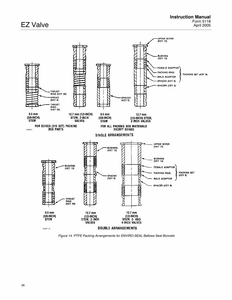
14. Install new packing and the metal packing boxparts according to the appropriate arrangement infigure 14 or 15.
15. Install the packing flange. Properly lubricate thepacking flange stud bolts and the faces of thepacking flange nuts.
For graphite packing, tighten the packing flange nutsto the maximum recommended torque shown in table4. Then, loosen the packing flange nuts, and retightenthem to the recommended minimum torque shown intable 4.
For other packing types, tighten the packing flangenuts alternately in small equal increments until oneof the nuts reaches the minimum recommendedtorque shown in table 4. Then, tighten the remainingflange nuts until the packing flange is level and at a90-degree angle to the valve stem.
16. Install travel indicator parts, stem locknuts, andmount the actuator on the valve body according tothe procedure in the appropriate actuator instructionmanual.
Replacing an Installed ENVIRO-SEALBellows Seal (Stem/Bellows Assembly)Instructions are provided for replacing anENVIRO-SEAL bellows seal (stem/bellowsassembly) when the existing valve has a metal seat.If the valve has a composition seat, refer to figure 13and to composition seat information in the Valveswith ENVIRO-SEAL Bellows Seal Bonnet procedureof the Trim Maintenance section.
1. Remove the actuator and bonnet according tosteps 1 through 5 of the Replacing Packingprocedure of the Maintenance section.
Note
With some valve plug sizes andconfigurations, the valve plug will slidethrough the seat ring retainer andbushing assembly, and in otherconfigurations it won’t. If the valve plugwill not slide through the seat ringretainer and bushing assembly, thenthe valve plug and stem assembly andthe seat ring retainer and bushingassembly must be removed together.
2. Using care, remove the valve plug and stemassembly, and, if necessary, the seat ring retainerand bushing assembly from the valve body. Removeand discard the existing bonnet gasket (key 10,figure 12) and gasket (key 22, figure 11). Cover thevalve body opening to protect sealing surfaces andto prevent foreign material from entering the valvebody cavity.
CAUTION
The ENVIRO-SEAL stem/bellowsassembly for easy-e valves is availableonly with a threaded and pinnedadaptor/stem connection. The existingvalve plug can be reused with the newstem/bellows assembly or a new plugcan be installed. If the existing valveplug is reused, and the adaptor is ingood condition, it may be reused also.However, to avoid weakening theadaptor that may cause failure inservice, never reuse an old adaptorwith a new valve plug. Using an oldadaptor with a new plug requiresdrilling a new pin hole in the adaptor,which will weaken the adaptor.However, a used valve plug may bereused with a new adaptor.

EZ ValveInstruction Manual
Form 5118April 2005
18
3. Inspect the existing valve plug and adaptor. If theyare in good condition, they can be reused with the newstem/bellows assembly, and they do not need to beseparated.
CAUTION
When removing/installing a valve plugon the ENVIRO-SEAL stem/bellowsassembly, the valve stem must not berotated. Damage to the bellows mayresult.
Do not grip the bellows shroud orother parts of the stem/bellowsassembly. Grip only the flat areas onthe stem where it extends out of thetop of the bellows shroud.
Note
The ENVIRO-SEAL stem/bellowsassembly has a one-piece stem.
4. If the existing valve plug and adaptor are not ingood condition and must be replaced, first, place theexisting stem/bellows assembly and valve plug andadaptor assembly in a soft-jaw chuck or other type ofvise so that the jaws grip a portion of the valve plugthat is not a seating surface. Drive out or drill out pin(key 8, figure 12). Drive out pin (key 36, figure 11).
5. Use a wrench on the flat areas on the valve stemjust below the threads for the actuator/stemconnection in a soft-jaw chuck or vice to keep thestem from turning. Then, unscrew the valve plugfrom the adaptor and the adaptor from thestem/bellows assembly.
6. To attach either the existing valve plug or a newone to the stem of the new ENVIRO-SEALstem/bellows assembly, it is necessary to first attachthe valve plug to the adaptor (key 24, figure 11), if thevalve plug was removed from the adaptor. Locate theadaptor. Notice that a hole has not been drilled in thenew adaptor threads where the valve plug screwsonto the adaptor.
If installing either a new valve plug and/or a newadaptor, secure the valve plug in a soft-jaw chuck orother type of vise. Do not grip the plug on any seatingsurface. Position the plug in the chuck or vise foreasy threading of the adaptor. Thread the adaptorinto the valve plug and tighten to the torque valuesgiven in figure 10.
7. Complete the installation by following steps 7through 16 of the Replacing a Plain or ExtensionBonnet with an ENVIRO-SEAL Bellows Seal andBonnet procedure provided in the previous section.
Purging the ENVIRO-SEAL Bellows SealBonnetThe ENVIRO-SEAL bellows seal bonnet has beendesigned so that it can be purged or leak tested.Refer to figure 11 for an illustration of anENVIRO-SEAL bellows seal bonnet, and perform thefollowing steps for purging or leak testing.
1. Remove the two diametrically opposed pipe plugs(key 16).
2. Connect a purging fluid to one of the pipe plugconnections.
3. Install appropriate piping or tubing in the otherpipe plug connection to pipe away the purging fluidor to make a connection to an analyzer for leaktesting.
4. When purging or leak testing has beencompleted, remove the piping or tubing and reinstallthe pipe plugs (key 16).
Parts OrderingEach valve is assigned a serial number which canbe found on the valve body. This same number alsoappears on the actuator nameplate when the valveis shipped from the factory as part of a control valveassembly. Refer to the serial number whencontacting your Fisher sales office for technicalassistance. When ordering replacement parts, referto the serial number and to the 11-character partnumber for each part required from the followingparts list.
Note
Use only genuine Fisher replacementparts. Components that are notsupplied by Fisher should not, underany circumstances, be used in anyFisher valve, because they will voidyour warranty, might adversely affectthe performance of the valve, andmight jeopardize worker andworkplace safety.

EZ ValveInstruction ManualForm 5118April 2005
19
Parts KitsGasket parts kits are in key 10 table.
Packing Kits (non-live-loaded)
Stem Diameter, mm (Inches)Yoke Boss Diameter, mm (Inches)
9.5 (3/8)54 (2-1/8)
12.7 (1/2)71 (2-13/16)
19.1 (3/4)90 (3-9/16)
PTFE (Contains keys 6, 8, 10, 11, and 12) RPACKX00012 RPACKX00022 RPACKX00032
Double PTFE (Contains keys 6, 8, 11, and 12) RPACKX00042(1)(2) RPACKX00052(1) RPACKX00062(1)
PTFE/Composition (Contains keys 7, 8, 11, and 12) RPACKX00072 RPACKX00082 RPACKX00092
Single Graphite Ribbon/Filament(Contains keys 7 [ribbon ring], 7 [filament ring], 8, and 11)
RPACKX00102 RPACKX00112 RPACKX00122
Double Graphite Ribbon/Filament(Contains keys 7 [ribbon ring], 7 [filament ring], 8, and 11)
RPACKX00162 RPACKX00172 RPACKX00182
1. These parts kits contain one extra lower wiper (key 30). Discard this extra part upon assembly.2. This parts kit contains one extra packing ring (key 7). Discard this extra part upon assembly.
Packing Kits (ENVIRO-SEAL) Repair
Stem Diameter, mm (Inches)Yoke Boss Diameter, mm (Inches)
9.5 (3/8)54 (2-1/8)
12.7 (1/2)71 (2-13/16)
19.1 (3/4)90 (3-9/16)
Double PTFE (Contains keys 214, 215, and 218) RPACKX00192 RPACKX00202 RPACKX00212
Graphite ULF (Contains keys 207, 208, 209, 210, and 214) RPACKX00592 RPACKX00602 RPACKX00612
Duplex (Contains keys 207, 209, 214, and 215) RPACKX00292 RPACKX00302 RPACKX00312
Packing Kits (ENVIRO-SEAL) Retrofit
Stem Diameter, mm (Inches)Yoke Boss Diameter, mm (Inches)
9.5 (3/8)54 (2-1/8)
12.7 (1/2)71 (2-13/16)
19.1 (3/4)90 (3-9/16)
Double PTFE (Contains keys 200, 201, 211, 212, 214, 215, 216, 217, and 218) RPACKXRT012 RPACKXRT022 RPACKXRT032
Graphite ULF (Contains keys 200, 201, 207, 208, 209, 210, 211, 212, 214, and 217) RPACKXRT262 RPACKXRT272 RPACKXRT282
Duplex (Contains keys 200, 201, 207, 209, 211, 212, 214, 215, 216, and 217) RPACKXRT212 RPACKXRT222 RPACKXRT232
Note
Neither Emerson, Emerson ProcessManagement, nor Fisher assumeresponsibility for the selection, use, ormaintenance of any product.Responsibility for proper selection,use, and maintenance of any Fisherproduct remains solely with thepurchaser and end-user.

EZ ValveInstruction Manual
Form 5118April 2005
20
Parts ListBonnet
Note
Part numbers are shown for recommended sparesonly. For part numbers not shown, contact yourFisher sales office.
Key Description Part Number1 Bonnet/ENVIRO-SEAL bellows seal bonnet
If you need a bonnet or an ENVIRO-SEAL bellows sealbonnet as a replacement part, order by valve size and stemdiameter, serial number, and desired material.
2 Baffle,(for extension bonnets only)3 Packing Flange, S31600 (316 SST)3 ENVIRO-SEAL Bellows Seal Packing Flange4 Packing Flange Stud, S31600 (2 req’d)4 ENVIRO-SEAL Bellows Seal Stud Bolt5 Packing Flange Nut, S31600 (2 req’d)5 ENVIRO-SEAL Bellows Seal Hex Nut6* Packing Set, PTFE (2 req’d for double packing)
9.5 mm (3/8-inch) stem 1R29000101212.7 mm (1/2-inch) stem 1R29020101219.1 mm (3/4-inch) stem 1R290401012
6* ENVIRO-SEAL Bellows Seal Packing SetPTFE for 9.5 mm (3/8-inch) stem (1 req’dfor single packing, 2 req’d for doublepacking) 12A9016X012
PTFE for size 2 with 12.7 mm (1/2 inch)stem (2 req’d for double packing) 12A9016X012
PTFE for size 3 and 4 with 12.7 mm(1/2 inch) stem (2 req’d for doublepacking) 12A8832X012
6* Packing Set, PTFE/KALREZ9.5 mm (3/8-inch) stem 13B0963X01212.7 mm (1/2-inch) stem 13B0964X01219.1 mm (3/4-inch) stem 13B0965X012
7* Packing Ring, PTFE/comp (fordouble packing)9.5 mm (3/8-inch) stemPTFE/comp (7 req’d) 1F3370X0012
12.7 mm (1/2-inch) stemPTFE/comp (10 req’d) 1E319001042
19.1 mm (3/4-inch) stemPTFE/comp (8 req’d) 1E319101042
7* Packing Ring, graphite ribbon ring (2 req’dfor single packing, 3 req’d for doublepacking)9.5 mm (3/8-inch) stem 1V3160X002212.7 mm (1/2-inch) stem 1V3802X002219.1 mm (3/4-inch) stem 1V2396X0022
7* Packing Ring, graphite filament ring9.5 mm (3/8-inch) stem (2 req’d for singlepacking, 4 req’d for double packing) 1F3370X032212.7 mm (1/2-inch) stem (3 req’d forsingle packing, 5 req’d for doublepacking) 1E3190X022219.1 mm (3/4-inch) stem (2 req’d forsingle packing, 4 req’d for doublepacking) 1E3191X0282
Key Description Part Number7* ENVIRO-SEAL Bellows Seal Packing Ring
for low chloride graphite ribbon/filamentpacking arrangementRibbon packing ring for 9.5 mm (3/8 inch)and size 2 with 12.7 mm (1/2 inch) stem(4 req’d) 18A0908X012
Filament packing ring for 9.5 mm(3/8 inch) and size 2 with 12.7 mm(1/2 inch) stem (4 req’d) 1P3905X0172
Ribbon packing ring for size 3 and 4with 12.7 mm (1/2 inch) stem (4 req’d) 18A0918X012
Filament packing ring for size 3 and 4with 12.7 mm (1/2 inch) stem (4 req’d) 14A0915X042
8 Spring, S31600 (for single PTFE packing only)8 Spacer, N04400 (Monel) (for single PTFE packing only)8 Lantern Ring (for double PTFE packing)8 ENVIRO-SEAL Bellows Seal Spring8 ENVIRO-SEAL Bellows Seal Spacer
10 Special Washer, S31600 (for single PTFE packing)11* Packing Box Ring
Single PTFE packing9.5 mm (3/8-inch) stemS31600 (std for S31600 and S41600 trims) 1J873135072N05500 (std for N05500 trim) 1J873146222
12.7 mm (1/2-inch) stemS31600 (std for S31600 and S41600 trims) 1J873235072N05500 (std for N05500 trim) 1J873246222
19.1 mm (3/4-inch) stemS31600 (std for S31600 and S41600 trims) 1J873335072N05500 (std for N05500 trim) 1J873346222
Double PTFE packing9.5 mm (3/8-inch) stemS31600 (std for S31600 and S41600 trims) 1J873135072Glass-filled PTFE (std for N05500 trim) 17A6872X012
12.7 mm (1/2-inch) stemS31600 (std for S31600 and S41600 trims) 1J873235072Glass-filled PTFE (std for N05500 trim) 17A6873X012
Double PTFE packing (cont’d)19.1 mm (3/4-inch) stemS31600 (std for S31600 and S41600 trims) 1J873335072Glass-filled PTFE (std for N05500 trim) 17A6874X012
PTFE/composition packing9.5 mm (3/8-inch) stemS31600 (std for S31600 and S41600 trims) 1J873135072Glass-filled PTFE (std for N05500 trim) 17A6872X012
12.7 mm (1/2-inch) stemS31600 (std for S31600 and S41600 trims) 1J873235072N05500 (std for N05500 trim) 1J873246222
19.1 mm (3/4-inch) stemS31600 (std for S31600 and S41600 trims) 1J873335072Glass-filled PTFE (std for N05500 trim) 17A6874X012
12* Upper Wiper, felt9.5 mm (3/8-inch) stem 1J87260633212.7 mm (1/2-inch) stem 1J87270633219.1 mm (3/4-inch) stem 1J872806332
12* ENVIRO-SEAL Bellows Seal Upper WiperFor 9.5 mm (3/8 inch) and size 2 with 12.7 mm(1/2 inch) stem 18A0868X012
For size 3 & 4 with 12.7 mm (1/2 inch) stem 18A0870X01213 Packing Follower
*Recommended spare parts

EZ ValveInstruction ManualForm 5118April 2005
21
Figure 11. Typical Bonnets
CU3911–D/IL 42B3947–A/IL
AU3910–A/IL

EZ ValveInstruction Manual
Form 5118April 2005
22
Key Description Part Number13* ENVIRO-SEAL Bellows Seal Bushing
For 9.5 mm (3/8 inch) stem (1 req’d),for size 2 with 12.7 mm (1/2 inch) stem, (2 req’d)S31600/PTFE 18A0820X012R30006 18A0819X012S31600/Cr Ct 11B1155X012
For size 3 and 4 with 12.7 mm (1/2 inch)stem (1 req’d)S31600/PTFE 18A0824X012R30006 18A0823X012S31600/Cr Ct 11B1157X012
13* ENVIRO-SEAL Bellows Seal Bushing/LinerFor 9.5 mm (3/8 inch) stem (1 req’d),for size 2 with 12.7 mm (1/2 inch) stem (2 req’d)N10276 bushing, PTFE/glass liner 12B2713X012N10276 bushing, PTFE/carbon liner 12B2713X042
For size 3 and 4 with 12.7 mm (1/2 inch)stem (1 req’d)N10276 bushing, PTFE/glass liner 12B2715X012N10276 bushing, PTFE/carbon liner 12B2715X042
14 Pipe Plug (not shown)14 Lubricator14 Lubricator/Isolating Valve15 Yoke Locknut15 ENVIRO-SEAL Bellows Seal Yoke Locknut16 Pipe Plug (not shown)16 ENVIRO-SEAL Bellows Seal Pipe Plug (2 req’d)20* ENVIRO-SEAL Bellows Seal Stem/Bellows
Assembly1 Ply BellowsS31603 trim mat’l, N06625 bellows mat’lSize 1 w/ 9.5 mm (3/8 inch) stem 32B4224X012Size 1.5 w/ 9.5 mm (0.375 inch) stem 32B4225X012Size 2 w/ 12.7 mm (1/2 inch) stem 32B4226X012Size 3 w/ 12.7 mm (1/2 inch) stem 32B4227X012Size 4 w/ 12.7 mm (1/2 inch) stem 32B4228X012
N06022 trim mat’l, N06022 bellows mat’lSize 1 w/ 9.5 mm (3/8 inch) stem 32B4224X022Size 1.5 w/ 9.5 mm (3/8 inch) stem 32B4225X022Size 2 w/ 12.7 mm (1/2 inch) stem 32B4226X022Size 3 w/ 12.7 mm (1/2 inch) stem 32B4227X022Size 4 w/ 12.7 mm (1/2 inch) stem 32B4228X022
2 Ply BellowsS31603 trim mat’l, N06625 bellows mat’lSize 1 w/ 9.5 mm (3/8 inch) stem 32B4224X032Size 1.5 w/ 9.5 mm (3/8 inch) stem 32B4225X032Size 2 w/ 12.7 mm (1/2 inch) stem 32B4226X032Size 3 w/ 12.7 mm (1/2 inch) stem 32B4227X032Size 4 w/ 12.7 mm (1/2 inch) stem 32B4228X032
N06022 trim mat’l, N06022 bellows mat’lSize 1 w/ 9.5 mm (3/8 inch) stem 32B4224X042Size 1.5 w/ 9.5 mm (3/8 inch) stem 32B4225X042Size 2 w/ 12.7 mm (1/2 inch) stem 32B4226X042Size 3 w/ 12.7 mm (1/2 inch) stem 32B4227X042Size 4 w/ 12.7 mm (1/2 inch) stem 32B4228X042
22* ENVIRO-SEAL Bellows Seal Bonnet Gasket(graphite/S31600)Size 0.5 through 1.25 12B6316X022Size 1.5 12B6317X022Size 2 12B6318X022Size 3 12B6319X022Size 4 12B6320X022
Key Description Part Number24 ENVIRO-SEAL Bellows Seal Adaptor27 Pipe Nipple, for lub/isolating valve,steel28 ENVIRO-SEAL Bellows Seal Nameplate, Warning29 ENVIRO-SEAL Bellows Seal Drive Screw (2 req’d)34 Lubricant, Never-Seez Nickel Special
or equivalent (not furnished with valve)36* ENVIRO-SEAL Bellows Seal Pin 12B3951X01237 ENVIRO-SEAL Bellows Seal Warning Tag38 ENVIRO-SEAL Bellows Seal Tie39 ENVIRO-SEAL Bellows Seal Thrust Ring
200 Stud (2 req’d)201 Packing Flange202 Spring, (2 req’d)203 Spring guide packing follower204 Screw, 18-8 SST (4 req’d)205 Load Scale, 18-8 SST (2 req’d)206 Indicator Disk, 18-8 SST207* Guide Bushing, white (2 req’d)
For ENVIRO-SEAL and HIGH-SEALpackingCarbon-graphitefor graphite packing9.5 mm (3/8-inch) stem 12B5780X01212.7 mm (1/2-inch) stem 12B5782X01219.1 mm (3/4-inch) stem 12B5784X012
208* Guide Bushing, no colorFor ENVIRO-SEAL and HIGH-SEAL packingCarbon-Graphite for graphite packing9.5 mm (3/8-inch) stem 12B5781X01212.7 mm (1/2-inch) stem 12B5783X01219.1 mm (3/4-inch) stem 12B5785X012
209* Packing Ring(1) (3 req’d)For ENVIRO-SEAL and HIGH-SEALpackingGraphite Compositefor graphite packing9.5 mm (3/8-inch) stem 12B5798X01212.7 mm (1/2-inch) stem 12B5799X01219.1 mm (3/4-inch) stem 12B5800X012
210* Packing Ring (2 req’d)For ENVIRO-SEAL and HIGH-SEALpackingGraphite Ribbonfor graphite packing9.5 mm (3/8-inch) stem 1V3160X002212.7 mm (1/2-inch) stem 1V3802X002219.1 mm (3/4-inch) stem 1V2396X0022
211* Packing Box RingFor ENVIRO-SEAL packingS31600For PTFE Packing9.5 mm (3/8-inch) stem 1J87313507212.7 mm (1/2-inch) stem 1J87323507219.1 mm (3/4-inch) stem 1J873335072
For ENVIRO-SEAL and HIGH-SEALpackingS31600For Graphite packing and Duplex packing9.5 mm (3/8-inch) stem 12B5774X01212.7 mm (1/2-inch) stem 12B5775X01219.1 mm (3/4-inch) stem 12B5776X012
212 Hex Nut (2 req’d)
*Recommended spare parts1. Part number is stamped on part.

EZ ValveInstruction ManualForm 5118April 2005
23
Key Description Part Number213 Lubricant, Never-Seez Nickel Special or equivalent214* Anti-Extrusion washer (4 req’d)
For ENVIRO-SEAL packingPTFE filled (off-white)For PTFE packing9.5 mm (3/8-inch) stem 12B6336X02212.7 mm (1/2-inch) stem 12B6335X02219.1 mm (3/4-inch) stem 12B6660X012
214* Packing Washer (5 req’d)For ENVIRO-SEAL packingPTFEFor Graphite packing and Duplex packing9.5 mm (3/8-inch) stem 12B6936X01212.7 mm (1/2-inch) stem 12B6937X01219.1 mm (3/4-inch) stem 12B6938X012
215* Packing Set (2 req’d)For ENVIRO-SEAL packingPTFE-carbon/PTFE9.5 mm (3/8-inch) stem 12B6663X01212.7 mm (1/2-inch) stem 12B6667X01219.1 mm (3/4-inch) stem 12B6671X012
216 Lantern Ring217 Spring Pack Assembly218* Lower wiper
For ENVIRO-SEAL packingPTFEFor PTFE packing9.5 mm (3/8-inch) stem 1J87210699212.7 mm (1/2-inch) stem 1J87220699219.1 mm (3/4-inch) stem 1J872306992
Valve Body1 Valve Body
If you need a valve body as a replacement part, order byvalve size, serial number, and desired material.
2* Valve Plug See following table3* Seat Ring Retainer (part numbers for the seat ring
retainer/bushing assy are provided in a following table)0.5, 0.75, & 1-inch valveCB7Cu-1 (17-4PH SST) 25A6683X012CF8M (316 SST) 25A6683X022M35-1 (Monel) 25A6683X052
1.5 inch valveCB7Cu-1 25A6685X012
1.5 inch valveCF8M 25A6685X022M35-1 25A6685X052
2-inch valveCB7Cu-1 25A6687X012CF8M 25A6687X022M35-1 25A6687X052
3-inch valveCB7Cu-1 25A6689X012CF8M 25A6689X022M35-1 25A6689X052
4-inch valveCB7Cu-1 35A6691X012CF8M 35A6691X022M35-1 35A6691X052
Key Description Part Number7* Stem See following table8* Pin See following table9* Seat Ring See following table
10* Bonnet Gasket See following table12* Spiral Wound Gasket See following table13* Seat Ring Gasket See following table15 Cap Screw or Stud Bolt16 Nut17 Pipe Plug, for use in valve bodies with drain tapping only18 Flow Arrow, SST19 Drive Screw, SST (4 req’d)25* Shim See following table26* Bushing See following table
(See additional table for part numbers ofassemblies that include both the seat ringretainer and the bushing)
27* Valve Plug Guide (for composition seatsonly) See following table
28* Disk Retainer, (composition seats only)6.4 mm (0.25-inch) port diameterS31600 16A3441X012N05500 16A3441X042S41600 16A3441X052
9.5 mm (0.375-inch) port diameterS31600 16A5706X012N05500 16A5706X042S41600 16A5706X052
29* Disk, PTFE (composition seats only)6.4 mm (0.25-inch) port diameter 13A1226X0629.5 mm (0.375-inch) port diameter 13A5125X04212.7 mm (0.5-inch) port diameter 1P69680624219.1 mm (0.75-inch) port diameter 1P69610624225.4 mm (1-inch) port diameter 1P69690624238.1 mm (1.5 inch) port diameter 1U27960624250.8 mm (2-inch) port diameter 1U27990624276.2 mm (3-inch) port diameter 1F5653X0012101.6 mm (4-inch) port diameter 16A3462X012
30* Tip (composition seats only) See following table31* Pin (composition seats only)
12.7 mm (0.5-inch) port diameterS31600 and S41600 1B599038992N05500 1B5990X0032
19.1 mm (0.75-inch) port diameterS31600 and S41600 1P730438992N05500 1P7304X0032
25.4 mm (1-inch) and 38.1 mm (1.5 inch)port diameterS31600 and S41600 1B599335072N05500 1B5993X00B2
50.8 mm (2-inch) port diameterS31600 and S41600 1B599538992N05500 1B599540032
32 Cap Screw (composition seat only)33 Nameplate, stainless steel34 Wire, lead
*Recommended spare parts
EZ ValveInstruction Manual
Form 5118April 2005
24
Figure 12. Design EZ Valve
E0994
16A1943–A

EZ ValveInstruction ManualForm 5118April 2005
25
Figure 13. Composition Seats for Design EZ Valve
46A1842–B
�������!��������� �����"���������!�����������"�!����������
������������ ����������!������������ ���������
����������"��!�����������������"��������
� ��������"��!�� �������������"��������#���"��������
EZ ValveInstruction Manual
Form 5118April 2005
26
Figure 14. PTFE Packing Arrangements for ENVIRO-SEAL Bellows Seal Bonnets
A5886–1/IL
A5885/IL
���������������
����������������� ���������������
���������������������$
���������������
����������������
����������������

EZ ValveInstruction ManualForm 5118April 2005
27
Figure 15. Double Graphite Ribbon/Filament Arrangements for ENVIRO-SEAL Bellows Seal BonnetsA5887–1/IL
���������������������$
���������������
�����������������
!��!������!�!!�������
Key 2* Micro-Flow and Micro-Flute Valve Plug
VALVEPORT
DIAMETERVALVE STEMCONNECTION
VALVE PLUG MATERIALVALVESIZE, VALVE
PLUGDIAMETER CONNECTION S31600 (316 SST)
N05500 S41600SIZE,INCH PLUG
mm Inch mm Inch
S31600 (316 SST)w/R30006 (Alloy 6)
Seat & Tip
N05500(K-Monel)
S41600(416 SST)
0.5, 0.75, 1,1.5, 2
Micro-FlowMicro-Flute (1 flute)Micro-Flute (3 flutes)
4.86.46.4
0.18750.250.25
9.5 3/82V9269503322U8682464222U868446422
1V1081462221U8445462221U844746222
1V1081461721U8445461721U844746172
*Recommended spare parts
EZ ValveInstruction Manual
Form 5118April 2005
28
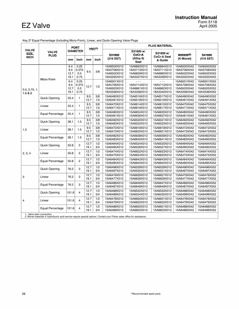
Key 2* Equal Percentage (Including Micro-Form), Linear, and Quick-Opening Valve Plugs
PORT VSC(1)PLUG MATERIAL
VALVESIZE, VALVE
PLUG
PORTDIAMETER
VSC(1)
S31600S31600 w/
CoCr-A S31600 w/N05500(2) S41600SIZE,
INCH PLUGmm Inch mm Inch
S31600(316 SST)
CoCr-A(Alloy 6)
Seat
S31600 w/CoCr-A Seat
& Guide
N05500(2)
(K-Monel)S41600
(416 SST)
Micro Form
6.49.512.719.1
0.250.3750.50.75
9.5 3/8
15A6500X01216A5708X01215A6502X01216A3335X012
15A6663X01216A5713X01215A6659X01216A3337X012
15A6664X01216A5711X01215A6660X01216A3339X012
15A6500X04216A5708X04215A6502X04216A3335X042
15A6500X05216A5708X05215A6502X05216A3335X052
0.5, 0.75, 1,1.5 & 2
Micro-Form6.49.512.719.1
0.250.3750.50.75
12.7 1/2
15A6501X01216A5709X01215A6503X01216A3336X012
- - -16A5714X01215A6661X01216A3338X012
- - -16A5712X01215A6662X01216A3340X012
15A6501X04216A5709X04215A6503X04216A3336X042
15A6501X05216A5709X05215A6503X05216A3336X0521.5 & 2
Quick Opening 25.4 1 9.512.7
3/81/2
15A6490X01215A6491X012
15A6516X01215A6518X012
15A6517X01215A6519X012
15A6490X04215A6491X042
15A6490X05215A6491X052
Linear 25.4 1 9.512.7
3/81/2
15A6470X01215A6471X012
15A6614X01215A6616X012
15A6615X01215A6617X012
15A6470X04215A6471X042
15A6470X05215A6471X052
Equal Percentage 25.4 1 9.512.7
3/81/2
15A6480X01215A6481X012
15A6634X01215A6636X012
15A6635X01215A6637X012
15A6480X04215A6481X042
15A6480X05215A6481X052
Quick Opening 38.1 1.5 9.512.7
3/81/2
15A6492X01215A6493X012
15A6520X01215A6522X012
15A6521X01215A6523X012
15A6492X04215A6493X042
15A6492X05215A6493X052
1.5 Linear 38.1 1.5 9.512.7
3/81/2
15A6472X01215A6473X012
15A6618X01215A6620X012
15A6619X01215A6621X012
15A6472X04215A6473X042
15A6472X05215A6473X052
Equal Percentage 38.1 1.5 9.512.7
3/81/2
15A6482X01215A6483X012
15A6638X01215A6640X012
15A6639X01215A6641X012
15A6482X04215A6483X042
15A6482X05215A6483X052
Quick Opening 50.8 2 12.719.1
1/23/4
15A6494X01215A6495X012
15A6524X01215A6526X012
15A6525X01215A6527X012
15A6494X04215A6495X042
15A6494X05215A6495X052
2, 3, 4 Linear 50.8 2 12.719.1
1/23/4
15A6474X01215A6475X012
15A6622X01215A6624X012
15A6623X01215A6625X012
15A6474X04215A6475X042
15A6474X05215A6475X052
Equal Percentage 50.8 2 12.719.1
1/23/4
15A6484X01215A6485X012
15A6642X01215A6644X012
15A6643X01215A6645X012
15A6484X04215A6485X042
15A6484X05215A6485X052
Quick Opening 76.2 3 12.719.1
1/23/4
15A6496X01215A6497X012
15A6528X01215A6530X012
15A6529X01215A6531X012
15A6496X04215A6497X042
15A6496X05215A6497X052
3 Linear 76.2 3 12.719.1
1/23/4
15A6476X01215A6477X012
15A6626X01215A6628X012
15A6627X01215A6629X012
15A6476X04215A6477X042
15A6476X05215A6477X052
Equal Percentage 76.2 3 12.719.1
1/23/4
15A6486X01215A6487X012
15A6646X01215A6648X012
15A6647X01215A6649X012
15A6486X04215A6487X042
15A6486X05215A6487X052
Quick Opening 101.6 4 12.719.1
1/23/4
15A6498X01215A6499X012
15A6532X01215A6534X012
15A6533X01215A6535X012
15A6498X04215A6499X042
15A6498X05215A6499X052
4 Linear 101.6 4 12.719.1
1/23/4
15A6478X01215A6479X012
15A6630X01215A6632X012
15A6631X01215A6633X012
15A6478X04215A6479X042
15A6478X05215A6479X052
Equal Percentage 101.6 4 12.719.1
1/23/4
15A6488X01215A6489X012
15A6650X01215A6652X012
15A6651X01215A6653X012
15A6488X04215A6489X042
15A6488X05215A6489X052
1. Valve stem connection.2. Monel materials in hydrofluoric acid service require special options. Contact your Fisher sales office for assistance.
*Recommended spare parts

EZ ValveInstruction ManualForm 5118April 2005
29
Key 2*, 7*, and 8* Valve Plug/Stem Assembly for Plain Bonnet
VALVEPORTDIA VSC(1)
PLUG MATERIALVALVESIZE, VALVE
PLUGDIA VSC(1)
S31600S31600 w/ S31600 w/
N05500(2) S41600SIZE,INCH PLUG
mm Inch mm InchS31600
(316 SST)
S31600 w/CoCr-A (Alloy 6)
Seat
S31600 w/CoCr-A Seat
& Guide
N05500(2)
(K-Monel)S41600
(416 SST)
Micro-FlowMicro-Flute (1 flute)Micro-Flute (3 flutes)
4.86.46.4
0.18750.250.25
9.5 3/8 - - - - - -2V9269X00A22U8682X00322U8684X0032
- - -1V1081X01421U8445X00321U8447X00E2
Micro Form
6.49.512.719.1
0.250.3750.50.75
9.5 3/8
15A6500X08216A5708X09215A6502X07216A3335X112
15A6663X02216A5713X03215A6659X02216A3337X042
15A6664X04216A5711X02215A6660X04216A3339X022
15A6500X15216A5708X18215A6502X10216A3335X212
15A6500X09216A5708X11215A6502X11216A3335X132
0.5, 0.75, 1,1.5, & 2
Micro-Form6.49.512.719.1
0.250.3750.50.75
12.7 1/2 x 3/8
- - -- - -
15A6502X16216A3335X142
- - -- - -
15A6659X08216A3337X032
15A6664X02216A5711X04215A6660X08216A3339X092
- - -
15A6500X25216A5708X13215A6502X15216A3335X182
Quick Opening 25.4 19.512.7
3/81/2 x 3/8
- - -- - -
15A6516X022- - -
15A6517X022- - -
- - -- - -
15A6490X09215A6490X072
Linear 25.4 19.512.7
3/81/2 x 3/8
15A6470X09215A6470X072
- - -- - -
15A6615X02215A6615X032
- - -- - -
15A6470X10215A6470X122
Equal Percentage 25.4 19.512.7
3/81/2 x 3/8
15A6480X10215A6480X202
15A6634X04215A6634X072
15A6635X02215A6635X042
15A6480X152- - -
15A6480X11215A6480X172
Quick Opening 38.1 1.5 9.5 3/8 15A6492X102 15A6520X032 15A6521X022 - - - 15A6492X082
1.5 Linear 38.1 1.5 9.5 3/8 15A6472X132 - - - 15A6619X022 - - - 15A6472X0721.5Equal Percentage 38.1 1.5 9.5 3/8 15A6482X102 15A6638X032 15A6639X022 - - - 15A6482X112
Quick Opening 50.8 2 12.7 1/2 15A6494X082 - - - 15A6525X022 - - - 15A6494X072
2 Linear 50.8 2 12.7 1/2 15A6474X132 - - - 15A6623X022 - - - 15A6474X0722Equal Percentage 50.8 2 12.7 1/2 15A6484X072 15A6642X042 15A6643X032 15A6484X102 15A6484X112
Quick Opening 50.8 2 12.7 1/2 - - - - - - - - - - - - 15A6494X092
Linear 50.8 2 12.7 1/2 15A6474X172 - - - - - - - - - 15A6474X152
3Equal Percentage 50.8 2 12.7 1/2 15A6484X152 - - - 15A6643X062 - - - 15A6484X172
3Quick Opening 76.2 3 12.7 1/2 15A6496X082 - - - 15A6529X022 - - - 15A6496X072
Linear 76.2 3 12.7 1/2 15A6476X092 - - - 15A6627X022 - - - 15A6476X082
Equal Percentage 76.2 3 12.7 1/2 15A6486X082 15A6646X022 15A6647X032 - - - 15A6486X062
Equal Percentage 50.8 2 12.7 1/2 - - - 15A6642X082 - - - - - - 15A6484X182
4Quick Opening 101.6 4 12.7 1/2 - - - - - - - - - - - - 15A6498X072
4Linear 101.6 4 12.7 1/2 15A6478X072 - - - - - - - - - 15A6478X062
Equal Percentage 101.6 4 12.7 1/2 15A6488X112 15A6650X022 15A6651X022 - - - 15A6488X0721. Valve stem connection.2. Monel materials in hydrofluoric acid service require special options. Contact your Fisher sales office for assistance.
Key 3*, 26* Seat Ring Retainer and Bushing Assembly(1) (2)
VALVE SEAT RING RETAINER/BUSHING MATERIALVALVESIZE,INCH
CB7Cu-1/S17400(17-4PH SST)
CF8M/R30006(316 SST/Alloy 6)
M35-1/N05500(3)
(Monel/K-Monel)
0.5, 0.75, & 1 25A6683X062 25A6683X072 25A6683X172
1.5 25A6685X072 25A6685X082 25A6685X142
2Full 25A6687X062 25A6687X112 25A6687X192
2Restricted 25A6687X092 25A6687X132 25A6687X182
3 25A6689X152 25A6689X132 25A6689X142
4Full 35A6691X062 35A6691X082 35A6691X092
4Restricted 35A6691X102 17A4161X082 35A6691X112
1. Seat ring retainer (only) part numbers are listed in the parts list on page 23.2. Micro-Flow and Micro-Flute constructions do not use bushings.3. Monel materials in hydrofluoric acid service require special options. Contact your Fisher sales office for assistance.
*Recommended spare parts

EZ ValveInstruction Manual
Form 5118April 2005
30
Key 7* Stem (for use with Group 1 Actuators)
VALVE SIZE, STEM DIAMETER STEM MATERIALVALVE SIZE,INCH mm Inch S31600 N05500 Nitronic 50 (NACE)
9.5 3/8 1U388835162 10A8823XA22 1U3888X0222
0.5, 0.75, 1, 1.5 12.7 1/2 1U388935162 1U3889X0012 1U3889X00420.5, 0.75, 1, 1.512.7 x 9.5 1/2 x 3/8 1U530935162 1U530946222 1U5309X0082
12.7 1/2 1U388935162 1U3889X0012 1U3889X0042
2 12.7 X 9.5 1/2 X 3/8 1U530935162 1U530946222 1U5309X0082219.1 3/4 1U226535162 1U226550192 1U2265X0042
312.7 1/2 1K586935162 10A8840XH32 1K5869X0102
319.1 3/4 10A9265XJ62 1U226550192 1U2265X0042
4 (restricted capacity 12.7 1/2 1J320535162 1J3205X0062 1J3205X00724 (restricted capacitytrim) 19.1 3/4 1U230835162 1U230847492 1U2308X0072
4 (full capacity trim)12.7 1/2 1K586935162 10A8840XH32 1K5869X0102
4 (full capacity trim)19.1 3/4 1U226535162 1U226550192 1U2265X0042
Key 8* Pin
VALVE SIZE,VALVE PLUG STYLE
VSC(1) PIN MATERIALVALVE SIZE,INCH VALVE PLUG STYLE
mm Inch S31600 (316 SST) N04400 (Monel)(2)
0 5 thru 2
Micro-Flow & Micro-Flute w/metal seats
9.5 3/8 1B599235072 1B599240032
0.5 thru 2Micro-Flute w/comp seats &Micro-Form
9.512.7
3/81/2
1B5993350721D5423X00B2
1B5993X00B21D5423X0012
0.5 thru 1.5 Linear, Equal Percentage &Quick Opening
9.512.7
3/81/2
1B5993350721D5423X00B2
1B5993X00B21D5423X0012
2
Linear, Equal Percentage &Quick Opening (full cap)
12.719.1
1/23/4
1B5998350721B813635072
1B5998400321B8136X0102
2Linear, Equal Percentage &Quick Opening (restricted port)
9.512.7
3/81/2
1B5993350721D5423X00B2
1B5993X00B21D5423X0012
3 All 12.719.1
1/23/4
1B5998350721B813635072
1B5998400321B8136X0102
4
Full Capacity 12.719.1
1/23/4
1B5998350721B813635072
1B5998X00C21B8136X0102
4Restricted 12.7
19.11/23/4
1B5993350721F723635072
1B5993X00B21B813640032
1. Valve stem connection.2. Monel materials in hydrofluoric acid service require special options. Contact your Fisher sales office for assistance.
*Recommended spare parts

EZ ValveInstruction ManualForm 5118April 2005
31
Key 9* Seat Ring (non-vaned) for Metal Seats
VALVESIZE
PORT DIA S31600 S31600 w/CoCr A (ALLOY 6)
S31600 w/CoCr A SEAT
N05500(1) S41600SIZE,INCH mm Inch
S31600(316 SST) CoCr-A (ALLOY 6)
SEATCoCr-A SEAT
& BORE
N05500( )
(K-MONEL)S41600
(416 SST)
0.5,0.75,and
4.86.49.5
12.7
0.18750.25
0.3750.5
1V1083350721U2852350721U2853350721U285435072
2V6262503322U8559460522U8560460522U856146052
25A5710X01225A5711X0121U2853X001226A0651X012
1V1083462221U2852462221U2853462221U825446222
1V1083461721U2852461721U2853461721U285446172and
1 19.1 0.75 1U285535072 2U856246052 - - - 1U2855X0092 1U285546172125.4 1 1U285635072 2U856346052 - - - 1U285646222 1U285646172
1.5
4.86.49.5
12.719.1
0.18750.25
0.3750.50.75
15A6512X01215A6513X01217A6075X01215A6514X01216A3350X012
25A8564X01215A6537X01227A6076X01215A6538X01226A3351X012
25A6536X01225A6539X01227A6079X01226A0653X01226A3352X012
15A6512X04215A6513X04217A6075X04215A6514X04216A3350X042
15A6512X05215A6513X05217A6075X05215A6514X05216A3350X052
25.4 1 15A6515X012 15A6654X012 - - - 15A6515X042 15A6515X052
38.1 1.5 15A6504X012 15A6655X012 - - - 15A6504X042 15A6504X052
2
4.86.49.5
12.719.1
0.18750.25
0.3750.50.75
15A6692X01215A6693X01217A4091X02215A6694X01216A3353X012
25A8565X01225A6698X01227A6080X01225A6699X01226A3354X012
25A6696X01225A6697X01227A6081X01226A0656X01226A3355X012
15A6692X04215A6693X04217A4091X05215A6694X04216A3353X042
15A6692X05215A6693X05217A4091X01215A6694X05216A3353X052
25.4 1 15A6695X012 25A1085X012 - - - 15A6695X042 15A6695X052
50.8 2 15A6505X012 15A6656X012 - - - 15A6505X042 15A6505X052
350.8 2 25A5713X012 25A5714X012 - - - 25A5713X042 25A5713X052
376.2 3 15A6506X012 15A6657X012 - - - 15A6506X042 15A6506X052
450.8 2 25A5715X012 25A5716X012 - - - 25A5715X042 25A5715X052
4101.6 4 15A6507X012 15A6658X012 - - - 15A6507X042 15A6507X052
1. Monel materials in hydrofluoric acid service require special options. Contact your Fisher sales office for assistance.
Key 9* Seat Ring (vaned) for Metal Seats(1)
VALVESIZE
PORT DIA CF8M CF8M w/CoCr A (ALLOY 6)
CA15SIZE,INCH mm Inch
CF8M(316 SST) CoCr-A (ALLOY 6)
SEAT
CA15(410 SST)(2)
0.5,0.75,
19.1 0.75 37B8773X012 38B0600X012 37B8773X0220.75,and1
25.4 1 37B8771X012 38B0601X012 37B8771X022
1 525.4 1 37B9001X012 38B0602X012 37B9001X022
1.538.1 1.5 37B8999X012 38B0603X012 37B8999X022
225.4 1 37B8765X012 38B0604X012 37B8765X022
250.8 2 37B8763X012 38B0605X012 37B8763X022
350.8 2 37B9009X012 38B0606X012 37B9009X022
376.2 3 37B9007X012 38B0607X012 37B9007X022
450.8 2 37B8781X012 38B0608X012 37B8781X022
4101.6 4 37B8779X012 38B0609X012 37B8779X022
1. Fisher recommends that the Performance+ vaned seat ring be used for non-viscous, flow-up, liquid applications.2. Vaned seat ring material is CA15 (410 SST) which is cast equivalent of S41600 (416 SST).
Key 9* Seat Ring (non-vaned) for Composition Seats
VALVESIZE,
PORTDIAMETER S31600
(316 SST)N05500(1)
(K MONEL)S41600
(416 SST)SIZE,INCH mm Inch
(316 SST) (K-MONEL) (416 SST)
0.5, 0.75, & 1 6.49.5
0.250.375
13A5872X01213A5873X012
13A5872X06213A5873X062
13A5872X02213A5873X032
1.5 6.49.5
0.250.375
16A3467X01217A6078X012
16A3467X04217A6078X042
16A3467X05217A6078X052
2 6.49.5
0.250.375
16A3468X01217A6077X012
16A3468X04217A6077X042
16A3468X05217A6077X052
1. Monel materials in hydrofluoric acid service require special options. Contact your Fisher sales office for assistance.
*Recommended spare parts

EZ ValveInstruction Manual
Form 5118April 2005
32
Key 10* Bonnet GasketKey 12* Spiral Wound GasketKey 13* Seat Ring GasketKey 25* Shim
Valve Size,Inch
KeyNumber
GasketSet 2(1)
GasketSet 3(1)
GasketSet 4(1)
Set RGASKETX162 10A8170X042 - - -
10 1R2859X0042 10A8163X012 1R2859X0042
0.5 - 0.75 & 1 12 1R286099442 10A8184X012 1R2860992920.5 0.75 & 113 1R2862X0062 10A8177X012 1R2862X0062
25 16A1936X012 16A1936X022 16A1936X022
Set RGASKETX172 10A8171X032 - - -
10 1R3101X0032 10A8164X012 1R3101X0032
1.5 12 1R309999442 10A8185X012 1R3099992921.513 1R3098X0052 10A8178X012 1R3098X0052
25 16A1937X012 16A1937X022 16A1937X022
Set RGASKETX182 10A8172X032 - - -
10 1R3299X0042 10A8165X012 1R3299X0042
2 12 1R329799442 10A8186X012 1R329799292213 1R3296X0042 10A8179X042 1R3296X0042
25 16A1938X012 16A1938X022 16A1938X022
Set RGASKETX202 10A8174X032 - - -
10 1R3484X0042 10A8167X012 1R3484X0042
3 12 1R348299442 10A8188X012 1R348299292313 1R3481X0052 10A8181X032 1R3481X0052
25 16A1940X012 16A1940X022 16A1940X022
Set RGASKETX212 - - -(2) - - -
10 1R3724X0042 10A8168X012 1R3724X0042
4 12 1R372299442 10A8189X012 1R372299292413 1J5047X0062 10A8182X032 1J5047X0062
25 16A1941X012 16A1941X022 16A1941X0221. See table below for description of gasket sets.2. Consult your Fisher sales office for gasket set part number.
Gasket Selection Criteria
Gasket Set Seat Ring Gasket Bonnet Gasket SpiralWound Gasket
Shim TemperatureCapabilities
2(1) 316 SST/graphiteflat sheet
316 SST/graphiteflat sheet
N06600 (Inconel)/graphite
S31600 –198 to 593�C(–325 to 1100�F)
3 PTFE-coated N04400(Monel)
PTFE-coated N04400 N04400/PTFE N04400 –73 to 149�C(–100 to 300�F)
4 316 SST/graphiteflat sheet
316 SST/graphiteflat sheet
N04400/composition N04400 –73 to 232�C(–100 to 450�F)
1. FGM gasket set.
*Recommended spare parts

EZ ValveInstruction ManualForm 5118April 2005
33
Key 26* Bushing
Valve Size, Inch S17400 (17-4PH SST) R30006 (Alloy 6) N05500 (K-Monel)(1)
0.5, 0.75, & 11.52 (rest. port)2 (full port)34 (rest. port)4 (full port)
15A6508X01215A7511X01215A6509X01215A6510X01215A7491X01215A5712X01215A6511X012
15A6508X02215A7511X02215A6509X02215A6510X02215A7491X02215A5712X02215A6511X022
15A6508X05215A7511X05215A6509X05215A6510X05215A7491X05215A5712X05215A6511X052
1. Monel materials in hydrofluoric acid service require special options. Contact your Fisher sales office for assistance.
Key 27* Valve Plug Guide (composition seat only)
VALVEVALVE STEMCONNECTION
PORT DIA MATERIALVALVEPLUG
mm Inch mm Inch S31600 (316 SST) N05500(1)
(K-Monel)S41600 (416 SST) S31600 w/CoCr-A (Alloy 6)
Micro-Flute 9.5 3/8 6.4 0.25 16A3440X012 16A3440X042 - - - 19A5814X012
Micro-Form
9.5 3/8
6.49.512.719.1
0.250.375
0.50.75
16A3440X01216A5703X01216A3445X01226A3449X012
16A3440X04216A5703X04216A3445X04226A3449X042
16A3440X05216A5703X05216A3445X05226A3449X052
19A5814X01219A5815X01217A7250X01228A8115X012Micro-Form
12.7 1/29.512.719.1
0.3750.5
0.75
16A5707X01216A3446X01226A3450X012
16A5707X04216A3446X04226A3450X042
16A5707X05216A3446X05226A3450X052
19A5815X01219A5817X01229A5812X012
Equal Percentage
9.512.79.512.712.719.112.719.1
3/81/23/81/21/23/41/23/4
25.425.438.150.876.276.2102102
11
1.523344
26A3453X01226A3454X01226A3457X01226A3460X01226A3470X01226A3471X01226A3463X01226A3464X012
26A3453X04226A3454X04226A3457X04226A3460X04226A3470X04226A3471X04226A3463X04226A3464X042
26A3453X05226A3454X05226A3457X05226A3460X05226A3470X05226A3471X05226A3463X05226A3464X052
29A5806X01229A5807X01228A1253X01229A5813X01229A5811X01229A5810X01229A5808X01229A5809X012
1. Monel materials in hydrofluoric acid service require special options. Contact your Fisher sales office for assistance.
*Recommended spare parts

EZ ValveInstruction Manual
Form 5118April 2005
34
Key 30* Tip
VALVESIZE VALVE PLUG
PORT DIA VALVE STEMCONNECTION
MATERIAL
SIZE,INCH
VALVE PLUGmm Inch mm Inch S31600
(316 SST)Alloy 6 N05500(1)
(K-Monel)S41600
(416 SST)Micro-Flute (1 flute)Micro-Flute (3 flutes)
6.4 0.25 9.5 3/8- - -- - -
13A5863X03213A5865X032
13A5863X04213A5865X022
- - -- - -
0.5, 0.75,1 1 5 Micro-Form
6.49.512.719.1
0.250.3750.50.75
9.5 3/8
13A6160X02216A5704X0121R9537X00221R9540X0012
- - -- - -- - -- - -
13A6160X06216A5704X0421R9537X00621R9540X0072
13A6160X01216A5704X0521R9537X00121R9540X0042
1, 1.5,& 2
Micro-Form9.512.719.1
0.3750.50.75
12.7 1/216A5704X0121R9537X00221R9540X0012
- - -- - -- - -
16A5704X0421R9537X00621R9540X0072
16A5704X0521R9537X00121R9540X0042
Equal Percentage25.438.150.8
11.52
9.5 & 12.79.512.7
3/8 & 1/23/81/2
1R95383507216A3458X01212A3889X012
- - -- - -- - -
1R9538X003216A3458X04212A3889X042
1R9538X001216A3458X05212A3889X052
3 Equal Percentage 76.2 3 12.7 & 19.1 1/2 & 3/4 16A3469X012 - - - 16A3469X042 16A3469X052
4 Equal Percentage 101.6 4 12.7 & 19.1 1/2 & 3/4 12A3760X022 - - - 12A3760X012 12A3760X0521. Monel materials in hydrofluoric acid service require special options. Contact your Fisher sales office for assistance.
Group 1 Actuators
54, 71, & 90 mm(2-1/8, 2-13/16, & 3-9/16 Inch) Yoke Boss
350—except 90 mm (3-9/16 inch) yoke boss472 & 473585C & 585CR603 & 1B644 & 645655657 & 667—76 mm (3-inch) max travel1008—except 90 mm (3-9/16 inch) yoke bosswith 51 mm (2-inch) travel
*Recommended spare parts

EZ ValveInstruction ManualForm 5118April 2005
35

EZ ValveInstruction Manual
Form 5118April 2005
36
Fisher Marshalltown, Iowa 50158 USACernay 68700 France Sao Paulo 05424 BrazilSingapore 128461
Emerson Process Management
www.Fisher.com
The contents of this publication are presented for informational purposes only, and while every effort has been made to ensure their accuracy, they arenot to be construed as warranties or guarantees, express or implied, regarding the products or services described herein or their use or applicability.We reserve the right to modify or improve the designs or specifications of such products at any time without notice.
Neither Emerson, Emerson Process Management, nor Fisher assume responsibility for the selection, use or maintenance of any Fisher product. Re-sponsibility for proper selection, use and maintenance of any Fisher product remains solely with the purchaser and end-user.
�Fisher Controls International LLC 1979, 2005; All Rights Reserved Printed in USA
ENVIRO-SEAL, HIGH-SEAL, easy-e, and Fisher are marks owned by Fisher Controls International LLC, a member of the Emerson ProcessManagement business division of Emerson Electric Co. The Emerson logo is a trademark and service mark of Emerson Electric Co. All other marksare the property of their respective owners. This product may be covered by one or more of the following patents: 5,129,625; 5,131,666; 5,056,757;5,230,498; and 5,299,812 or under pending patents.