design, fabrication, and testing of the modular ... · pnnl-sa-122060 1 design, fabrication, and...
TRANSCRIPT

PNNL-SA-122060 1
Design, Fabrication, and Testing of the Modular Hydrothermal Liquefaction System (MHTLS) JUSTIN BILLING, DAN ANDERSON, RICH HALLEN, TODD HART, GARY MAUPIN, ANDY SCHMIDT, DOUG ELLIOTT November 3, 2016 TCS 2016 Symposium on Thermal and Catalytic Sciences for Biofuels and Biobased Products The Friday Center, University of North Carolina-Chapel Hill

Since Last Year…
Water Environment & Reuse Foundation (WE&RF) issued a final report (August 2016) describing the hydrothermal processing of WWTP sludges (first presented at tcbiomass2015)
Available at werf.org Partners include DOE, EPA, municipalities, PNNL, Genifuel, industry consultants
Wet wastes and waste-to-energy has become a primary focus for advanced HTL processing
2
https://www.werf.org/i/a/ka/Search/ResearchProfile.aspx?ReportId=LIFT6T14

3
Outline
Process History and Overview Scale-up Challenges Identified During Development of Bench Scale Systems Design, Fabrication, and Delivery of the Modular Hydrothermal Liquefaction System (MHTLS) Process Scale-up Factors and Challenges Addressed by the MHTLS

4
HTL Timeline (General and at PNNL)
1970s Process Development • Batch and
Model Compounds
1980s Pilot Demon-strations • Albany • Shell HTU • PERC, LBL
2008-2010 Renewed Process Development • Continuous-Flow Process • No Reducing Agent • Agricultural Residues
US DOE Consortia • 2011-2014
NABC • 2010-2013
NAABB
2014-Present Process Scale-up • Genifuel • MHTLS • Steeper • HTU
Go big or go home!

HTL-to-Fuel Overview
5
Hydrothermal Liquefaction (HTL) Conversion of a biomass slurry (e.g., wet waste, wood, algae) to biocrude and aqueous product
300–350°C 2800–3000 psig
HTL
Slurry Feedstock
Biocrude Product Aqueous Product
(contains organics)
+
Catalytic Hydrotreatment
Distillation
Fuel Fractions
Hydrotreated Bio oil
Biocrude is upgraded via Catalytic Hydrotreatment and fractionated by Distillation to gasoline, diesel, jet fuel, and bottoms
6
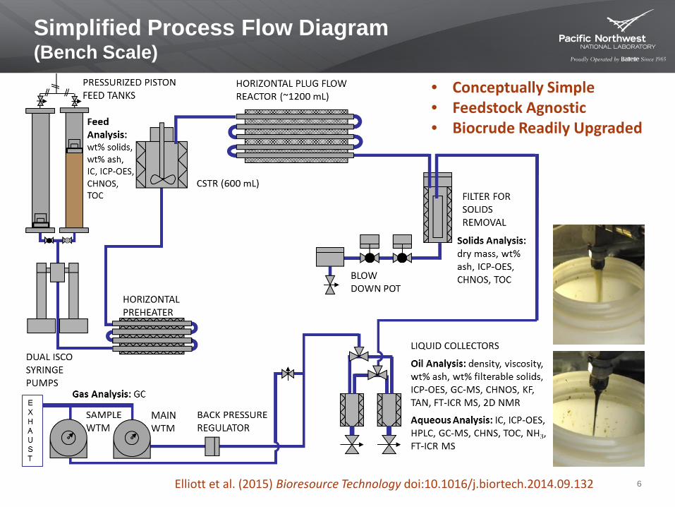
Simplified Process Flow Diagram (Bench Scale)
• Conceptually Simple • Feedstock Agnostic • Biocrude Readily Upgraded
Elliott et al. (2015) Bioresource Technology doi:10.1016/j.biortech.2014.09.132

HTL at PNNL – Current Test Stand
7
CSTR
Pre-Heater
Main Reactor
Membrane coalescer
Gas BPR
Blow down
Liq. BPR
Badger Valve
Filter
Product Collection
20-liter feed tank
Walk in hood: 7’(L) x 3’(W) x 8’(H)
Current test stands are operated in continuous mode at feed rates of 1 – 4 liters per hour
Commissioned in 2014
Micro GC
Wet Test Meter Wet Test
Meter
8
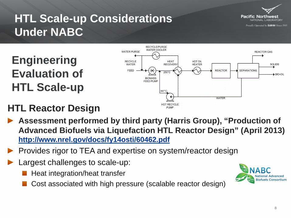
HTL Reactor Design Assessment performed by third party (Harris Group), “Production of Advanced Biofuels via Liquefaction HTL Reactor Design” (April 2013) http://www.nrel.gov/docs/fy14osti/60462.pdf Provides rigor to TEA and expertise on system/reactor design Largest challenges to scale-up:
Heat integration/heat transfer Cost associated with high pressure (scalable reactor design)
HTL Scale-up Considerations Under NABC
Engineering Evaluation of HTL Scale-up

9
Feed formatting/pumping At bench scale, with small tubes (~ 1 cm), feedstock formatted to paste consistency, generally conservative to avoid plugging Meaningful pumpability testing must be done at close to plant scale to determine acceptable particle size and slurry maximum concentration
Heat transfer coefficient during slurry heating Need rapid liquefaction to reduce viscosity and increase heat transfer, accurately determine heat transfer coefficient Injection of hot recycle stream – the loop reactor
Hydrothermal Liquefaction Scale-up Challenges
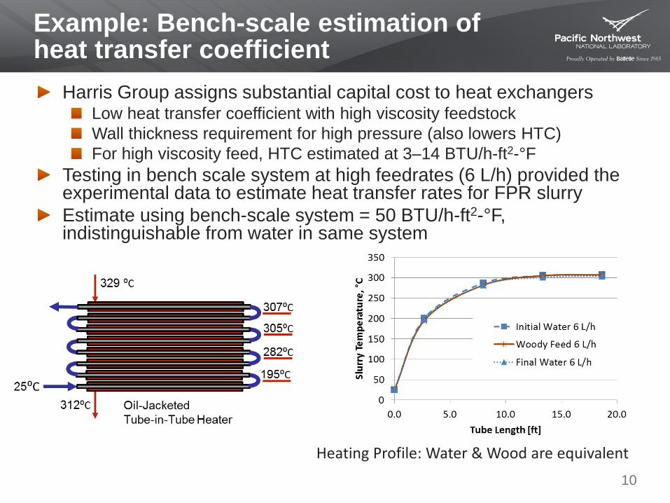
Example: Bench-scale estimation of heat transfer coefficient
Harris Group assigns substantial capital cost to heat exchangers Low heat transfer coefficient with high viscosity feedstock Wall thickness requirement for high pressure (also lowers HTC) For high viscosity feed, HTC estimated at 3–14 BTU/h-ft2-°F
Testing in bench scale system at high feedrates (6 L/h) provided the experimental data to estimate heat transfer rates for FPR slurry Estimate using bench-scale system = 50 BTU/h-ft2-°F, indistinguishable from water in same system
10
Heating Profile: Water & Wood are equivalent

11
Hydrothermal Liquefaction Scale-up Challenges
Reactor design Continuous stirred tank reactors work well at bench/engineering scale, but need efficient plug flow reactor to minimize capital costs Assumptions on plug flow need to be tested in a pilot system with slurry feed rates on the order of 1 to 4 L/min (i.e., ~ 20 to 60X scale up from the continuous flow system used).
Depressurization Rapid letdown of entire product stream by proportional valve or back-pressure regulator (BPR) BPR for gas phase, liquid via level control
12
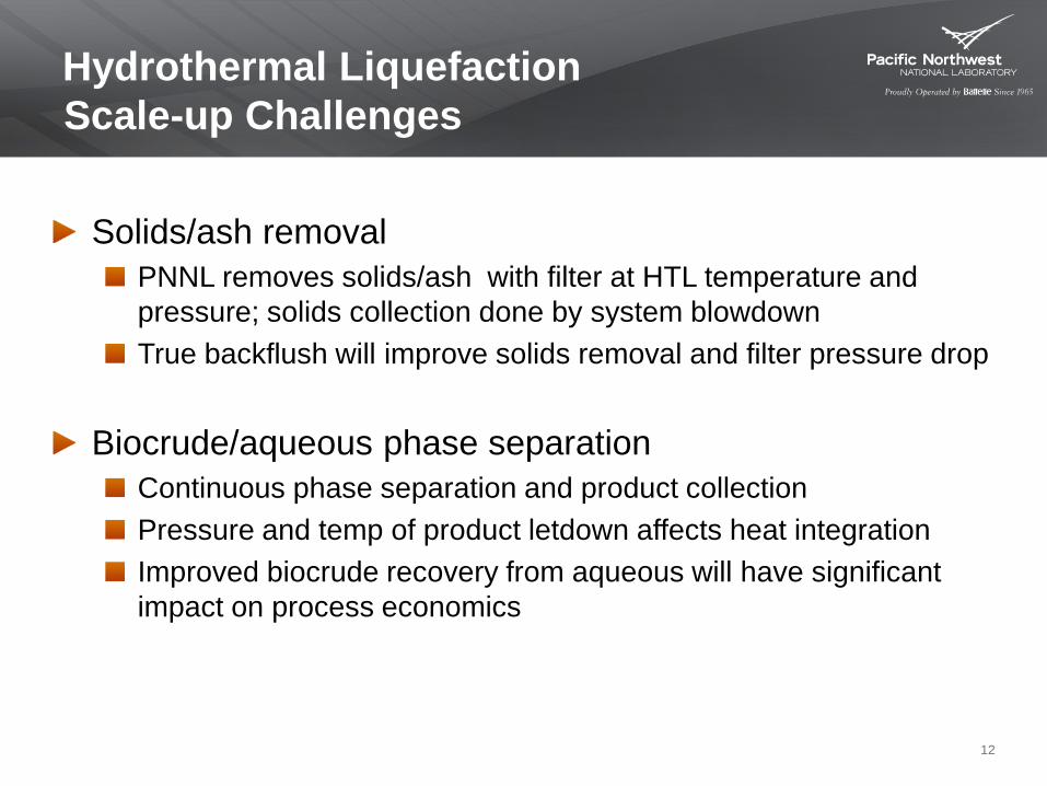
Hydrothermal Liquefaction Scale-up Challenges
Solids/ash removal PNNL removes solids/ash with filter at HTL temperature and pressure; solids collection done by system blowdown True backflush will improve solids removal and filter pressure drop
Biocrude/aqueous phase separation Continuous phase separation and product collection Pressure and temp of product letdown affects heat integration Improved biocrude recovery from aqueous will have significant impact on process economics

MHTLS: Design to Delivery
13
Functional Design Criteria
April 2015
Request for Proposal
April 2015
Award to Zeton
August 2015
Preliminary Hazard
Analysis August 2015
90% Design Review
Complete December
2015
Fabrication December
2015 to May 2016
Factory Acceptance
Testing June to July
2016
Delivery, Installation,
Commissioning August 2016 to
Present

14
MHTLS Layout
Skid 1 Feed Preparation
Skid 2 HTL Processing
Skid 3 Separations
12 ft (3.7 m)
Skid footprint is 36 × 16 ft (11.0 x 4.9 m)

15
MHTLS Footprint
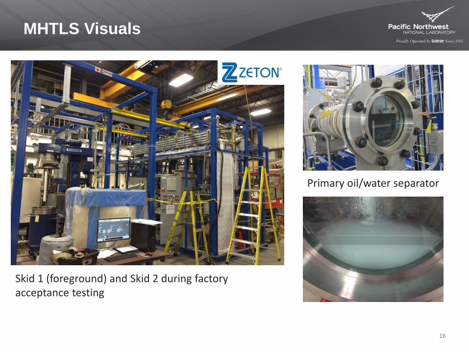
MHTLS Visuals
16
Skid 1 (foreground) and Skid 2 during factory acceptance testing
Primary oil/water separator
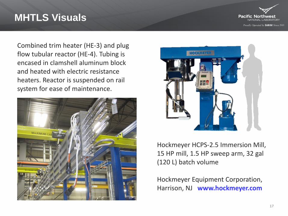
MHTLS Visuals
17
Hockmeyer HCPS-2.5 Immersion Mill, 15 HP mill, 1.5 HP sweep arm, 32 gal (120 L) batch volume Hockmeyer Equipment Corporation, Harrison, NJ www.hockmeyer.com
Combined trim heater (HE-3) and plug flow tubular reactor (HE-4). Tubing is encased in clamshell aluminum block and heated with electric resistance heaters. Reactor is suspended on rail system for ease of maintenance.

MHTLS Simplified Process Flow Diagram
18
Feed Day Tank
Cooler
HP Feed Pump
Blo
wdo
wn
LP Pump
HP Water Pump
Trim Heater H-3
Sep
arat
or
Plug Flow Reactor H-4
Heat exchanger H-1
Badger Valve
Gas Separator
Oil/Water Separator
Vent Gas
Biocrude Aqueous Stream
Filter Solids
Filte
rs
Blow- down
Receipt
Building Water
From Feed Staging Tank
Back Flush Line
To BD-2

At a Glance: Scale-Up Factors
Units Bench-Scale MHTLS Scale-Up
Slurry Flow Rate L/h 1.5–4.0 (2.0)
12–16 (12)
3–10× (6×)
Dry Biomass Feed Rate (15-20 wt%) kg/day 5.7–20.2
(7.6) 45.4–80.6
(45.4) 2–14× (6×)
Biocrude production rate (30-40% yield) kg/day 1.7–8.1
(2.3) 13.6–32.3
(13.6) 2–19× (6×)
Reactor Volume (PFR) L 0.5-1.0 (0.5) 3.0 3–6×
(6×)
Axial Velocity cm/s 1.1–2.9a
(1.4) 4.8-6.4b
(4.8) 2–6× (4×)
Reactor Enclosure Volume (Skid 2) m3 4.76 43.5 9×
Feed prep batch size kg 20-40 120 3–6×
19
Nominal values are in parentheses. (a) Assumes ⅜” OD tubing (b) Assumes ½” OD tubing
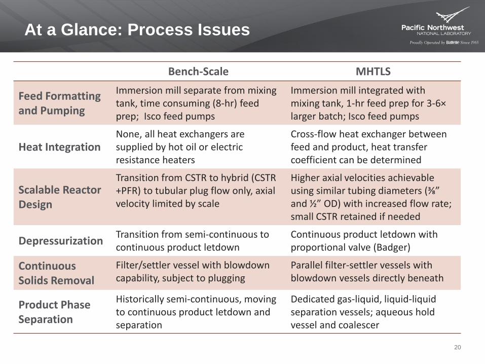
At a Glance: Process Issues
Bench-Scale MHTLS
Feed Formatting and Pumping
Immersion mill separate from mixing tank, time consuming (8-hr) feed prep; Isco feed pumps
Immersion mill integrated with mixing tank, 1-hr feed prep for 3-6× larger batch; Isco feed pumps
Heat Integration None, all heat exchangers are supplied by hot oil or electric resistance heaters
Cross-flow heat exchanger between feed and product, heat transfer coefficient can be determined
Scalable Reactor Design
Transition from CSTR to hybrid (CSTR +PFR) to tubular plug flow only, axial velocity limited by scale
Higher axial velocities achievable using similar tubing diameters (⅜” and ½” OD) with increased flow rate; small CSTR retained if needed
Depressurization Transition from semi-continuous to continuous product letdown
Continuous product letdown with proportional valve (Badger)
Continuous Solids Removal
Filter/settler vessel with blowdown capability, subject to plugging
Parallel filter-settler vessels with blowdown vessels directly beneath
Product Phase Separation
Historically semi-continuous, moving to continuous product letdown and separation
Dedicated gas-liquid, liquid-liquid separation vessels; aqueous hold vessel and coalescer
20

Factory Acceptance Testing and Current Schedule
21
Factory Acceptance Testing FAT-1: I/O, cause-and-effect, safety interlocks, calibration FAT-2: prepare and transfer a batch of pine slurry FAT-3: continuous separation of mineral oil and water FAT-4: achieve process conditions (T, P, flow) and heat integration in plug flow configuration FAT-5: achieve process conditions (T, P, flow) in CSTR configuration FAT-6: servicing and maintenance
Delivery, Installation, and Current Schedule
Receipt in two shipments: August 22 and 29, 2016 Installation: reassemble skids, connect to utilities, receive permits, completed installation October 11, 2016 Operational readiness: prepare procedures and receive authorization to start testing (currently underway)

22
Acknowledgements
Much of work summarized here and the capital expenditure for the MHTLS was supported by the U.S. Department of Energy's Bioenergy Technologies Office (BETO).
At PNNL, we acknowledge Rolando Lara for his help with contracts and procurement, Tyler Gilmore for his project management support, and Pete Lowry for his timely engagement in hazards analysis. Bill Dey and Emily Wilson provided superb and efficient QA support.
The design expertise and leadership from Zeton, Inc. was outstanding. Special acknowledgement is due to Scott Cooper (project lead), as well as Chris Brown, Chris Hart, Erik Gaspar, and many others.

Back Up Slides
23
Pump Assessment Photos of Feedstocks HTL compared to pyrolysis History of HTL (with references)

Identified three types of positive displacement pumps (five vendors) to meet the production rate of 2000 DMTPD (2300 gpm, 15 wt%, 3000 psi), report issued Relevant applications include industrial/municipal sludge, pastes, fibers, silage High confidence in ability to pump immersion milled feedstock; testing required to determine pumpability of larger particle size feedstock Large-scale pumping demonstration required with actual feeds, flow rates, pressures, and temps up to 250°C
Need large quantities of feed and a suitable facility
24
Pump Assessment Outcome
Slump Test
REPORT “Review and Assessment of Commercial Vendors/Options for Feeding and Pumping Biomass Slurries for Hydrothermal Liquefaction” http://www.pnnl.gov/main/publications/external/technical_reports/PNNL-21981.pdf

25
Pump Options (High Pressure)
Hose-Diaphragm Pumps - Feluwa
Double piston pump
Slump Test
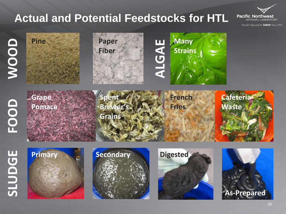
Actual and Potential Feedstocks for HTL
26
FOO
D W
OO
D
ALG
AE
SLU
DGE
Pine Paper Fiber
Spent Brewer’s Grains
Grape Pomace
French Fries
Cafeteria Waste
Many Strains
Primary Secondary Digested
As-Prepared

November 3, 2016 27
PNNL-SA-XXXXXX
Liquefaction of Biomass to Biocrude: Fast Pyrolysis and HTL
Conditions Fast pyrolysis Hydrothermal liquefaction feedstock Dry Biomass Wet biomass operating temperature 450-500°C 350°C environment inert gas aqueous condense phase catalyst none alkali reagent operating pressure 1 atm 200 atm residence time < 1 sec 5 to 30 min carbon yield to biocrude 70% 50% oil product quality heating value (HHV, Btu/lb) 6,900 Btu/lb 14,200 Btu/lb
oxygen content 40% <15% water content 25% 5% viscosity@40 °C low (50 cSt) high (4,000 cSt) thermal stability no yes
28 PNNL-SA-XXXXXX
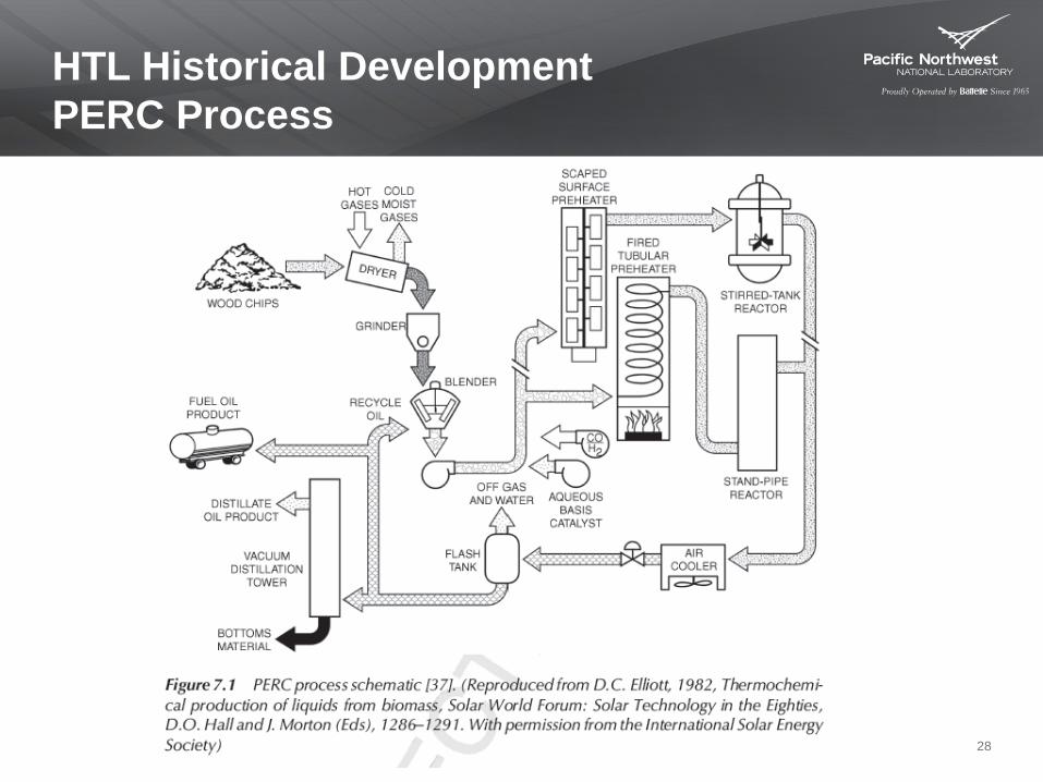
HTL Historical Development PERC Process

29
HTL Development LBL Process

30
HTL Development HTU Pilot Plant

References for PERC, LBL & HTU PERC and LBL Process References
DC Elliott, Chapter 7: Hydrothermal Processing, Thermochemical Processing of Biomass: Conversion into Fuels, Chemicals and Power, Edited by Robert C Brown, 2011, John Wiley & Sons. Rust International Corporation. 1982. Final Report, An Investigation of Liquefaction of Wood at the Biomass Liquefaction Facility Albany, Oregon, Pacific Northwest Laboratory, Contract B-B2471-a-g and Department of Energy Contract DE AC01-78ET 23032, Wheelabrator Cleanfuel Corporation. Released as report PNL-5114, Pacific Northwest Laboratory, Richland, Washington.
HTU References: Berends, R.H., Zeevalkink, J.A., Goudriaan F., and Naber J.E. (2004) Results of the first long duration run of the HTU pilot plant at TNO-MEP, in Biomass for Energy, Industry, and Climate Protection: Proceedings of 2nd World Conference Held in Rome, Italy, 10–14 May 2004 (eds W.P.M. van Swaaij, T. Fj€allstr€om, P. Helm, and A. Grassi), ETA-Florence, Florence, pp. 535–537 (ISBN 3-936338-16-7). Goudriaan, F. and Naber, J.E. (2006) HTU process design and development: innovation involves many disciplines, in Science in Thermal and Chemical Biomass Conversion, (eds A.V. Bridgwater and D.G.B. Boocock) CPL Press, Newbury, pp. 1069–1081. Goudriaan, F, van de Beld, B., Boerefijn, F.R. et al., (2001) Thermal efficiency of the HTU process for biomass liquefaction, in Progress in Thermochemcial Biomass Conversion (ed. A.V. Bridgwater), Blackwell Science, Oxford, pp. 1312–1325.. Goudriaan, F. and DGR Peferoen 1990 Liquid Fuels from Biomass via a Hydrothermal Process. Chemical Engineering Science. Vol 45. No. 9, pp. 2729-2734.
31