design for manufacturing and assembly key …design for manufacturing and assembly (dfma) has great...
TRANSCRIPT

General rights Copyright and moral rights for the publications made accessible in the public portal are retained by the authors and/or other copyright owners and it is a condition of accessing publications that users recognise and abide by the legal requirements associated with these rights.
Users may download and print one copy of any publication from the public portal for the purpose of private study or research.
You may not further distribute the material or use it for any profit-making activity or commercial gain
You may freely distribute the URL identifying the publication in the public portal If you believe that this document breaches copyright please contact us providing details, and we will remove access to the work immediately and investigate your claim.
Downloaded from orbit.dtu.dk on: Apr 05, 2020
Design for manufacturing and assembly key performance indicators to support high-speed product development
Thompson, Mary Kathryn; Juel Jespersen, Ida Kirstine; Kjærgaard, Thomas
Published in:Procedia CIRP
Link to article, DOI:10.1016/j.procir.2018.02.005
Publication date:2018
Document VersionPublisher's PDF, also known as Version of record
Link back to DTU Orbit
Citation (APA):Thompson, M. K., Juel Jespersen, I. K., & Kjærgaard, T. (2018). Design for manufacturing and assembly keyperformance indicators to support high-speed product development. Procedia CIRP, 70, 114-119.https://doi.org/10.1016/j.procir.2018.02.005
ScienceDirect
Available online at www.sciencedirect.comAvailable online at www.sciencedirect.com
ScienceDirectProcedia CIRP 00 (2017) 000–000
www.elsevier.com/locate/procedia
2212-8271 © 2017 The Authors. Published by Elsevier B.V. Peer-review under responsibility of the scientific committee of the 28th CIRP Design Conference 2018.
28th CIRP Design Conference, May 2018, Nantes, France
A new methodology to analyze the functional and physical architecture of existing products for an assembly oriented product family identification
Paul Stief *, Jean-Yves Dantan, Alain Etienne, Ali Siadat École Nationale Supérieure d’Arts et Métiers, Arts et Métiers ParisTech, LCFC EA 4495, 4 Rue Augustin Fresnel, Metz 57078, France
* Corresponding author. Tel.: +33 3 87 37 54 30; E-mail address: [email protected]
Abstract
In today’s business environment, the trend towards more product variety and customization is unbroken. Due to this development, the need of agile and reconfigurable production systems emerged to cope with various products and product families. To design and optimize productionsystems as well as to choose the optimal product matches, product analysis methods are needed. Indeed, most of the known methods aim to analyze a product or one product family on the physical level. Different product families, however, may differ largely in terms of the number and nature of components. This fact impedes an efficient comparison and choice of appropriate product family combinations for the productionsystem. A new methodology is proposed to analyze existing products in view of their functional and physical architecture. The aim is to clusterthese products in new assembly oriented product families for the optimization of existing assembly lines and the creation of future reconfigurable assembly systems. Based on Datum Flow Chain, the physical structure of the products is analyzed. Functional subassemblies are identified, and a functional analysis is performed. Moreover, a hybrid functional and physical architecture graph (HyFPAG) is the output which depicts the similarity between product families by providing design support to both, production system planners and product designers. An illustrativeexample of a nail-clipper is used to explain the proposed methodology. An industrial case study on two product families of steering columns of thyssenkrupp Presta France is then carried out to give a first industrial evaluation of the proposed approach. © 2017 The Authors. Published by Elsevier B.V. Peer-review under responsibility of the scientific committee of the 28th CIRP Design Conference 2018.
Keywords: Assembly; Design method; Family identification
1. Introduction
Due to the fast development in the domain of communication and an ongoing trend of digitization anddigitalization, manufacturing enterprises are facing importantchallenges in today’s market environments: a continuingtendency towards reduction of product development times andshortened product lifecycles. In addition, there is an increasingdemand of customization, being at the same time in a global competition with competitors all over the world. This trend, which is inducing the development from macro to micro markets, results in diminished lot sizes due to augmentingproduct varieties (high-volume to low-volume production) [1]. To cope with this augmenting variety as well as to be able toidentify possible optimization potentials in the existingproduction system, it is important to have a precise knowledge
of the product range and characteristics manufactured and/or assembled in this system. In this context, the main challenge inmodelling and analysis is now not only to cope with single products, a limited product range or existing product families,but also to be able to analyze and to compare products to definenew product families. It can be observed that classical existingproduct families are regrouped in function of clients or features.However, assembly oriented product families are hardly to find.
On the product family level, products differ mainly in twomain characteristics: (i) the number of components and (ii) thetype of components (e.g. mechanical, electrical, electronical).
Classical methodologies considering mainly single products or solitary, already existing product families analyze theproduct structure on a physical level (components level) which causes difficulties regarding an efficient definition andcomparison of different product families. Addressing this
Procedia CIRP 70 (2018) 114–119
2212-8271 © 2018 The Authors. Published by Elsevier B.V.Peer-review under responsibility of the scientific committee of the 28th CIRP Design Conference 2018.10.1016/j.procir.2018.02.005
© 2018 The Authors. Published by Elsevier B.V.Peer-review under responsibility of the scientific committee of the 28th CIRP Design Conference 2018.
Procedia CIRP 00 (2017) 000–000
www.elsevier.com/locate/procedia
2212-8271 © 2017 The Authors. Published by Elsevier B.V. Peer-review under responsibility of the scientific committee of the 28th CIRP Design Conference 2018.
28th CIRP Design Conference, May 2018, Nantes, France
Design for manufacturing and assembly key performance indicators to support high-speed product development
Mary Kathryn Thompsona,*, Ida Kirstine Juel Jespersena, Thomas Kjærgaardb a Department of Mechanical Engineering, Technical University of Denmark, Lyngby 2800, Denmark
bQuality and Environment Department, Grundfos, A/S, Bjerringbro, 8850, Denmark
* Corresponding author. E-mail address: [email protected]
Abstract
Design for Manufacturing and Assembly (DfMA) has great potential for minimizing late engineering changes (ECs) that impede high-speed product development and delay time-to-profit. However, our understanding of DfMA and its implementation in industry is still incomplete. This paper presents an industrial case study on late ECs in high-speed product development and compares the results to other examples from the literature. It then proposes a framework with sets of key performance indicators (KPIs) to measure and improve producability and product quality throughout the product development process. © 2017 The Authors. Published by Elsevier B.V. Peer-review under responsibility of the scientific committee of the 28th CIRP Design Conference 2018.
Keywords: Product Development; Design for Manufacturing and Assembly; Concurrent Engineering; Engineering Change Management
1. Introduction
It has long been known that production considerations and constraints must be included from the earliest stages of the product development process [1-5]. Failure to do so increases development costs [6-7], manufacturing costs [7-10], late engineering changes (ECs) [2,12-13], and the overall time-to-market [4,12,14]. Design for Manufacturing and Assembly (DfMA), especially when combined with concurrent engineering [10,16], can help avoid these problems. However, our understanding of DfMA and its implementation are still incomplete. This paper examines the role of DfMA in high-speed product development. It begins with a brief review of DfMA and concurrent engineering in product development processes. Next, it presents an industrial case study on late engineering changes in high-speed product development and compares the results to other examples from the literature. Finally, it proposes a framework with sets of key performance indicators (KPIs) to measure and improve producability and product quality throughout the product development process.
2. Prior Art
Numerous scholars have recognized the importance of DfMA in concurrent engineering [4,10,17-18], however, the exact relationship between the two remains unclear. For example, Boothroyd et al. argued that DfMA is the basis for concurrent engineering [4], while Anderson [10] and Bralla [17] argued that concurrent engineering should frame the application of DfMA. Sohlenius [16] took a broader view, suggesting that DfMA should be used during concurrent engineering to incorporate production considerations into the design process.
Sohlenius’ perspective is mostly commonly reflected in product development process models. For example, Ulrich and Eppinger’s [18] product development process defines the sequence for performing various design and manufacturing activities. However, their model only introduces process considerations after the preliminary structure of the design concept has been set. Similarly, Pahl and Beitz [19], French [20], and Cross [21] introduce production considerations only after concept selection is complete. O’Driscoll’s model [9] is one of the few that shows product development activities in

Mary Kathryn Thompson et al. / Procedia CIRP 70 (2018) 114–119 1152 Author name / Procedia CIRP 00 (2018) 000–000
parallel with cost estimating, process and material selection, and other quality activities. O’Driscoll’s DfMA framework was also the only one identified during this literature review which included checkpoints, such as DfMA questionnaires, during the product development process. The topic of KPIs in the context of DfMA and product development processes is otherwise poorly addressed in the literature.
3. Case Study
Grundfos A/S is a global leader in the design and manufacture of advanced technology pumps. Grundfos competes internationally on quality and innovation, rather than on cost and time-to-market. However, recent changes in the competitive and regulatory environments (including new EU regulations restricting the sale of low energy efficiency pumps) have necessitated additional focus on cost reduction and high-speed new product development. In 2013, Grundfos began developing new energy efficient circulator pumps for the commercial building services market. The circulator product family is a modular platform offering two major variants, each with two model sizes: small and medium/large. The development projects for the two variants were inter-dependent and therefore competed for resources, especially in terms of experienced personnel with expertise in DfMA. As a result, both projects required numerous late engineering changes, which led to delays and cost overruns.
The case study presented in this work focuses on one of these two projects (RW). The project was initiated by the Grundfos Quality & Environment Department to improve DfMA in their high-speed product development process and to ensure First Time Right design. The case study involved background research on the Grundfos product development process and their DfMA tools and techniques, an analysis of the engineering change notes in the RW project, and interviews and workshops with the product development and production organizations at Grundfos.
3.1. Background
Grundfos uses a stage gate product development process with 7 development phases (DPs): idea, pre-study, concept, development, preparation, production start-up, and sales (Fig. 1). At DP4, technical responsibility is handed over from design to manufacturing, and the design is frozen. All changes after DP4 are recorded in an engineering change note.
Fig. 1. Grundfos product development process with milestones and reviews
The design and engineering activities within the product development process follow a mechanical process model that maps 9 engineering life-cycle processes at the product
development level (design, implementation, integration, testing, and verification of product, hardware, software, and mechanical requirement specifications) to the first 5 stages of the Grundfos product development process (Fig. 2). The mechanical process model also includes 6 processes that span all 7 stages of the product development process: configuration management, quality assurance, project management, quality management, risk management, and supplier management. Since the mechanical process model does not show which activities are required to complete the defined processes, it is used mainly by the project managers rather than by the designers.
Various activities are used to control, document, and track the project during mechanical development. These include the design phase (gate) passages, design reviews (informal meetings to exchange ideas and experiences), status reviews (formal meetings to prepare for design phase passages), 0-meetings (the formal handover from design to production), engineering change notes, and the Design Journal. The 0-meetings are intended to verify that agreement has been reached on the production concept, tolerances, the control method(s), the measuring method(s), and the measuring plan. After the 0-meeting, production and measurement tooling and equipment is purchased. The Design Journal contains all technical documentation of the product, including design considerations and engineering changes. While the Design Journal contains many lessons learned, it is used mainly by the Quality Department after the sales release.
Fig. 2. Schematic of the Grundfos mechanical process model (details and support and management processes omitted)
3.2. Overview of Design for Manufacturing and Assembly at Grundfos
At Grundfos, Design for Manufacturing (DfM) and Design for Assembly (DfA) are separate activities. Both are owned by the Quality Department. DfA is a well-established activity used to ensure efficient assembly of products. It includes component functional analysis, failure elimination analysis, component handling analysis, component insertion analysis, extra operation analysis, data analysis, and brainstorming. DfA is usually done during a one-day workshop hosted by a Quality representative using a spreadsheet and formal design guides. In contrast, DfM activities were not clearly defined in the Grundfos stage gate model until recently. At Grundfos, DfM is intended to involve production earlier in the product development process and focuses on improving quality and reducing time to profit. DfM activities or ‘concepts’ include
1 2 3 4 5 6
Project milestone Status review Design review
Idea Pre-study Concept Development t Preparation Production start up Sales
DP2 DP3 DP4 DP5 DP6 DP1
Idea Pre-study Concept Development t Preparation Production start up Sales
DP2 DP3 DP4 DP5 DP6 DP1

116 Mary Kathryn Thompson et al. / Procedia CIRP 70 (2018) 114–119 Author name / Procedia CIRP 00 (2017) 000–000 3
the 0-meeting, DfA workshops, design guides, geometrical product specifications (GPS), tolerance limits, QS-Stat (a historical production database), tolerance chains, design reviews, FMEA, and a Critical-to-Quality classification of measurements for technical drawings. Many of these ‘concepts’ are not associated with classical DfMA in the literature. They are included in the Grundfos definition because of their intent to “design with consideration to production capabilities”. DfM activities at Grundfos are often carried out ad hoc by experienced personnel. This practice created the shortfall in expertise that originally motivated the case study.
3.3. Analysis of Engineering Change Notes from RW
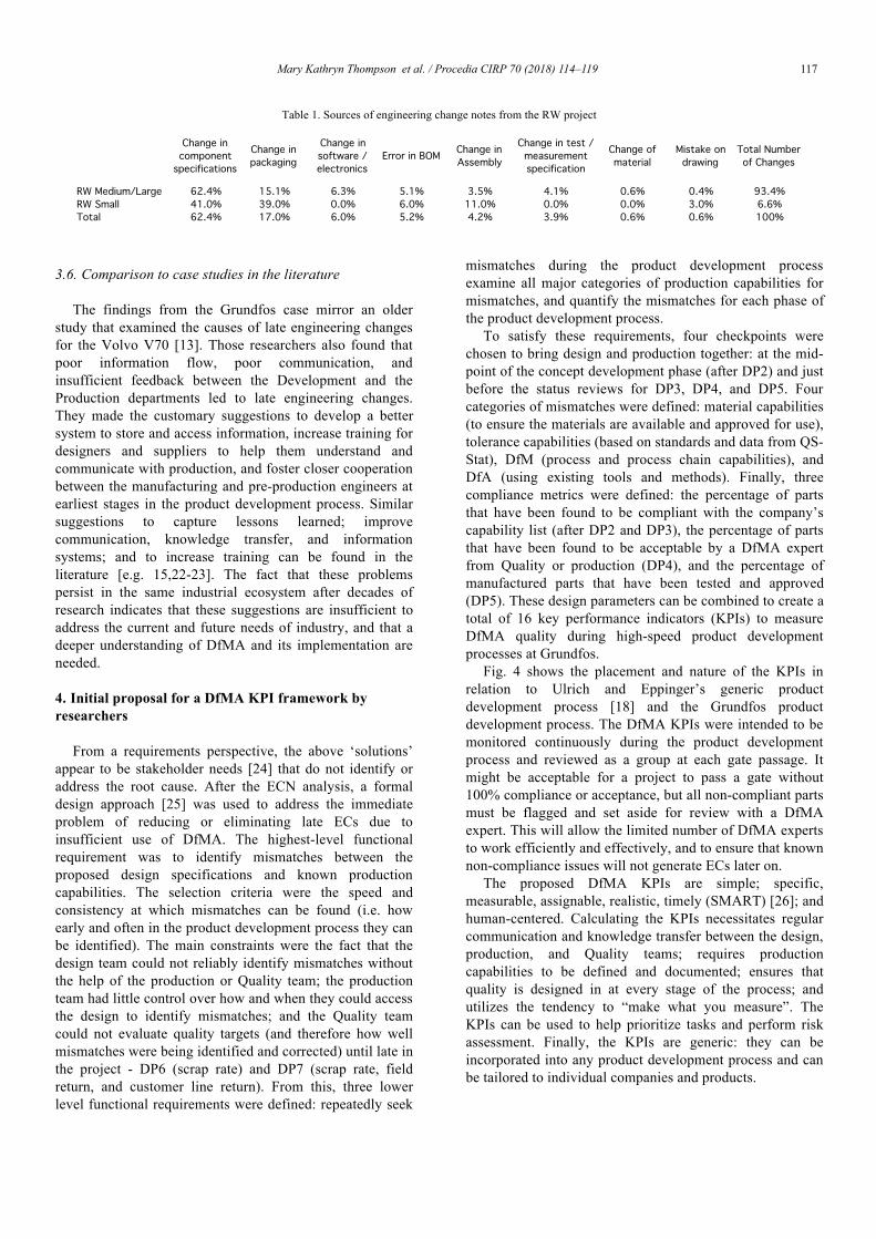
More than 1300 engineering change notes (ECNs) were created for the RW project. Over 93% of these were for the medium/large variant, mainly because work on that variant began first. An analysis revealed that most ECNs were related to component specifications (e.g. changes in geometry and tolerances), followed by changes in packaging (Table 1). Packaging changes were inevitable because all packaging decisions in the RW project were postponed until after DP4. The distribution of ECNs by fiscal quarter (every 3 months) is shown in Fig. 3. The ECNs recorded before DP4 indicate the release of drawings to SAP. DP5 was postponed and combined with DP6 due to the large number of changes after design freeze. 56% of all ECNs were recorded after the sales release (DP6).
The ECN analysis has some limitations. Not all ECNs indicate a problem. For example, ECNs are created each time a component drawing is released to SAP. In addition, ECNs are difficult to characterize due to the limited information contained within. An ECN could record a change for a single variation or for all variations. Finally, not all ECNs were related to DfMA.
To gain more insight, the ECNs for a component that required substantial post-design-freeze changes were examined in detail. The distribution of the ECNs for this component had the same pattern as the distribution of all ECNs: each ECN contained multiple changes to the specifications, geometry, material, tolerances, and tooling. Most of these issues were related to injection molding (e.g. filling, ejection, shrinkage, surface quality, strength of the final part, etc.). The final conclusion of the ECN analysis was that most of the changes were related to a failure to design products according to the company’s production requirements and capabilities.
Fig. 3. Distribution of ECNs for RW Medium/Large by fiscal quarter
3.4. Observations from interviews and the workshop
After the ECN analysis was complete, interviews were conducted to identify and discuss root cause(s), and a workshop was held to identify potential solutions. These revealed four general observations. (1) DfMA related tools and processes at the company were well established, but awareness and access to them was limited and usage varied greatly by individual and department. Experts with many years in the company tend to rely on their experience; they do not use the formal tools and methods, and are therefore unable to introduce them to new employees. New employees reported that the existing tools and design guides were difficult to find, difficult to use without training, and caused them to experience information overload. (2) Well-established tools and methods were not always used or used as intended due to time constraints. The designers reported that they had de-emphasized the use of formal tools and methods under time pressure. This was possible because the follow-up procedure to ensure that DfMA tools and methods had been used (a single point on a checklist: Has a DFA analysis been conducted?) was too general to ensure compliance. The designers and engineers similarly reported that they had not used the historical data from QS-Stat, tolerance limits, or design guides in development. In addition, the production engineers reported that they approved tolerances and designs at the 0-meeting without evidence of production feasibility. These factors contributed to the many tolerance-related ECNs. (3) Communication and management issues between the design and production teams contributed to the high number of ECNs. This was partially because the two teams worked at different sites. However, the production engineers also felt that an ‘over-the-wall’ design process was being used. The designers confirmed this, admitting that their engagement with, and therefore the involvement of, production during the product development process is highly dependent on the designers’ personal experience and network. As a result, component production requirements were not specified or communicated. This led to challenges in assembly and assembly-related ECNs. (4) The designers and engineers noted that lessons during projects learned are poorly documented or go un-documented. As a result, problems like those describe above tend to recur.
3.5. Recommendations from the workshop
The workshop identified issues related to personnel, data, and project management; communication; training; the use of standards; and institutional awareness and memory of lessons learned. However, these seemed to be symptoms of a deeper problem and were ultimately set aside because so participants could focus on improving DfMA in the Grundfos product development process. This left three recommendations: (1) the 0-meeting should be improved (e.g. redefined or restructured) to ensure that it fulfills its purpose, (2) KPIs are needed to estimate product manufacturability and predict quality early in the project, and (3) the product development process should be restructured to consider technical and production capabilities earlier.
DP4 DP5/6 Software / Elec.
Test / Meas. Spec.
Drawing
BOM
Packaging
Material
Component Spec.
Assembly
Mary Kathryn Thompson et al. / Procedia CIRP 70 (2018) 114–119 1174 Author name / Procedia CIRP 00 (2018) 000–000
Table 1. Sources of engineering change notes from the RW project
3.6. Comparison to case studies in the literature
The findings from the Grundfos case mirror an older study that examined the causes of late engineering changes for the Volvo V70 [13]. Those researchers also found that poor information flow, poor communication, and insufficient feedback between the Development and the Production departments led to late engineering changes. They made the customary suggestions to develop a better system to store and access information, increase training for designers and suppliers to help them understand and communicate with production, and foster closer cooperation between the manufacturing and pre-production engineers at earliest stages in the product development process. Similar suggestions to capture lessons learned; improve communication, knowledge transfer, and information systems; and to increase training can be found in the literature [e.g. 15,22-23]. The fact that these problems persist in the same industrial ecosystem after decades of research indicates that these suggestions are insufficient to address the current and future needs of industry, and that a deeper understanding of DfMA and its implementation are needed.
4. Initial proposal for a DfMA KPI framework by researchers
From a requirements perspective, the above ‘solutions’ appear to be stakeholder needs [24] that do not identify or address the root cause. After the ECN analysis, a formal design approach [25] was used to address the immediate problem of reducing or eliminating late ECs due to insufficient use of DfMA. The highest-level functional requirement was to identify mismatches between the proposed design specifications and known production capabilities. The selection criteria were the speed and consistency at which mismatches can be found (i.e. how early and often in the product development process they can be identified). The main constraints were the fact that the design team could not reliably identify mismatches without the help of the production or Quality team; the production team had little control over how and when they could access the design to identify mismatches; and the Quality team could not evaluate quality targets (and therefore how well mismatches were being identified and corrected) until late in the project - DP6 (scrap rate) and DP7 (scrap rate, field return, and customer line return). From this, three lower level functional requirements were defined: repeatedly seek
mismatches during the product development process examine all major categories of production capabilities for mismatches, and quantify the mismatches for each phase of the product development process.
To satisfy these requirements, four checkpoints were chosen to bring design and production together: at the mid-point of the concept development phase (after DP2) and just before the status reviews for DP3, DP4, and DP5. Four categories of mismatches were defined: material capabilities (to ensure the materials are available and approved for use), tolerance capabilities (based on standards and data from QS-Stat), DfM (process and process chain capabilities), and DfA (using existing tools and methods). Finally, three compliance metrics were defined: the percentage of parts that have been found to be compliant with the company’s capability list (after DP2 and DP3), the percentage of parts that have been found to be acceptable by a DfMA expert from Quality or production (DP4), and the percentage of manufactured parts that have been tested and approved (DP5). These design parameters can be combined to create a total of 16 key performance indicators (KPIs) to measure DfMA quality during high-speed product development processes at Grundfos.
Fig. 4 shows the placement and nature of the KPIs in relation to Ulrich and Eppinger’s generic product development process [18] and the Grundfos product development process. The DfMA KPIs were intended to be monitored continuously during the product development process and reviewed as a group at each gate passage. It might be acceptable for a project to pass a gate without 100% compliance or acceptance, but all non-compliant parts must be flagged and set aside for review with a DfMA expert. This will allow the limited number of DfMA experts to work efficiently and effectively, and to ensure that known non-compliance issues will not generate ECs later on.
The proposed DfMA KPIs are simple; specific, measurable, assignable, realistic, timely (SMART) [26]; and human-centered. Calculating the KPIs necessitates regular communication and knowledge transfer between the design, production, and Quality teams; requires production capabilities to be defined and documented; ensures that quality is designed in at every stage of the process; and utilizes the tendency to “make what you measure”. The KPIs can be used to help prioritize tasks and perform risk assessment. Finally, the KPIs are generic: they can be incorporated into any product development process and can be tailored to individual companies and products.
Change in component
specifications
Change in packaging
Change in software / electronics
Error in BOM Change in Assembly
Change in test / measurement specification
Change of material
Mistake on drawing
Total Number of Changes
RW Medium/Large 62.4% 15.1% 6.3% 5.1% 3.5% 4.1% 0.6% 0.4% 93.4%RW Small 41.0% 39.0% 0.0% 6.0% 11.0% 0.0% 0.0% 3.0% 6.6%Total 62.4% 17.0% 6.0% 5.2% 4.2% 3.9% 0.6% 0.6% 100%

118 Mary Kathryn Thompson et al. / Procedia CIRP 70 (2018) 114–119Author name / Procedia CIRP 00 (2017) 000–000 5
Fig. 4. Original DfMA KPIs mapped onto Ulrich and Eppinger’s generic product development process [21] and the original Grundfos PDP
Fig. 5. Final Producability KPIs for the Grundfos stage gate product development process model
5. Final proposal for a Producability KPI framework in industry
After the formal conclusion of the research project, the proposed DfMA KPIs and the associated framework were extended by Grundfos to create a complete system of Producability KPIs (Fig. 5). Again, check points were defined for four stages: conceptual design (DP1-DP3), development (DP3-DP4), production preparation and ramp-up (DP4-DP6), and sales (DP6-DP7). The first stage identifies and evaluates drivers for complexity so the associated risks can be reduced. These KPIs include the number of new parts, materials, tools, processes, and vendors required; the number of new or increased production (e.g. tolerance) and quality requirements; and the number of new coupled functional requirements in the proposed design. The second and third stages estimate the producability of the proposed design. The second stage relies on expert evaluation of the design using a simple rubric based on the original DfMA KPIs. The third stage extended the original DfMA KPIs to include the percentage of equipment and tooling that were approved. The fourth stage expanded the original Grundfos quality KPIs for DP6-DP7 to include tooling and equipment factors such as up-time and maintenance.
This system is part of a larger ongoing project to improve the Grundfos product development process, and is therefore not yet in use. However, a well-structured product development process combined with detailed evaluation rubrics has been successful in increasing innovation, and in
improving design quality, designer compliance with formal design theories and processes, and consistency in implementing control measures in an educational setting [27-29]. It is expected that similar success will be achieved in industry.
6. Discussion
Integrating KPIs linking design, production, and quality throughout a product development process is a simple and tangible step that can clarify expectations, improve communication, and improve compliance, thereby reducing or eliminating ECNs, and facilitating high-speed product development. However, the KPIs do not address the root cause(s) for a failure to achieve First Time Right design and production. Part of the problem likely stems from a failure to adequately define DfMA. Thompson et al. recently argued that DfMA should be viewed from three levels of abstraction: (1) concrete tools, techniques, and guidelines to adapt a design to a given set of downstream constraints; (2) a framework to understand and quantify the effect of the design process on manufacturing (and vice versa), and (3) an exploration of the relationship between design and manufacturing and its impact on the designer, the design process, and design practice [30]. This work began by examining DfMA at Grundfos at the first level to determine if specific tools and guidelines were available, understood, and in use. However, it finished at the third level by exploring how manufacturing impacts the designer and the design process.
DP3: % of parts compliant with the capability list
Product Quality KPIs:
DP4: % of parts accepted by an expert
DP5: % of tested and approved parts
Planning Concept Development
System-Level
Design Detail
Design Testing and Refinement
Production Ramp-Up
Full Scale Production
Production Capability Knowledge
KPI parameters: Material Tolerancing Design for Manufacturing Design for Assembly
Idea Pre-study Concept Development Preparation Production
start up Sales
DP2 DP3 DP4 DP5 DP6 DP1
After DP2: % of parts compliant with the capability list
DP2 DP3 DP4 DP5 DP6 DP1
# New parts, materials, tools, processes, vendors # New or increased production requirements # New or increased quality requirements # New coupled functional requirements
% Material capability compliant % Tolerance capability complaint % Design for Manufacture % Design for Assembly
% Parts approved % Equip. approved
Drivers of Complexity Estimating Producability
% Parts with capability on target % Parts with scrap rate on target % Equipment with up time on target % Equipment with maintenance on target
Production Achieved
Idea Pre-study Concept Development Prep. Production
Startup Sales

Mary Kathryn Thompson et al. / Procedia CIRP 70 (2018) 114–119 119Author name / Procedia CIRP 00 (2017) 000–000 5
Fig. 4. Original DfMA KPIs mapped onto Ulrich and Eppinger’s generic product development process [21] and the original Grundfos PDP
Fig. 5. Final Producability KPIs for the Grundfos stage gate product development process model
5. Final proposal for a Producability KPI framework in industry
After the formal conclusion of the research project, the proposed DfMA KPIs and the associated framework were extended by Grundfos to create a complete system of Producability KPIs (Fig. 5). Again, check points were defined for four stages: conceptual design (DP1-DP3), development (DP3-DP4), production preparation and ramp-up (DP4-DP6), and sales (DP6-DP7). The first stage identifies and evaluates drivers for complexity so the associated risks can be reduced. These KPIs include the number of new parts, materials, tools, processes, and vendors required; the number of new or increased production (e.g. tolerance) and quality requirements; and the number of new coupled functional requirements in the proposed design. The second and third stages estimate the producability of the proposed design. The second stage relies on expert evaluation of the design using a simple rubric based on the original DfMA KPIs. The third stage extended the original DfMA KPIs to include the percentage of equipment and tooling that were approved. The fourth stage expanded the original Grundfos quality KPIs for DP6-DP7 to include tooling and equipment factors such as up-time and maintenance.
This system is part of a larger ongoing project to improve the Grundfos product development process, and is therefore not yet in use. However, a well-structured product development process combined with detailed evaluation rubrics has been successful in increasing innovation, and in
improving design quality, designer compliance with formal design theories and processes, and consistency in implementing control measures in an educational setting [27-29]. It is expected that similar success will be achieved in industry.
6. Discussion
Integrating KPIs linking design, production, and quality throughout a product development process is a simple and tangible step that can clarify expectations, improve communication, and improve compliance, thereby reducing or eliminating ECNs, and facilitating high-speed product development. However, the KPIs do not address the root cause(s) for a failure to achieve First Time Right design and production. Part of the problem likely stems from a failure to adequately define DfMA. Thompson et al. recently argued that DfMA should be viewed from three levels of abstraction: (1) concrete tools, techniques, and guidelines to adapt a design to a given set of downstream constraints; (2) a framework to understand and quantify the effect of the design process on manufacturing (and vice versa), and (3) an exploration of the relationship between design and manufacturing and its impact on the designer, the design process, and design practice [30]. This work began by examining DfMA at Grundfos at the first level to determine if specific tools and guidelines were available, understood, and in use. However, it finished at the third level by exploring how manufacturing impacts the designer and the design process.
DP3: % of parts compliant with the capability list
Product Quality KPIs:
DP4: % of parts accepted by an expert
DP5: % of tested and approved parts
Planning Concept Development
System-Level
Design Detail
Design Testing and Refinement
Production Ramp-Up
Full Scale Production
Production Capability Knowledge
KPI parameters: Material Tolerancing Design for Manufacturing Design for Assembly
Idea Pre-study Concept Development Preparation Production
start up Sales
DP2 DP3 DP4 DP5 DP6 DP1
After DP2: % of parts compliant with the capability list
DP2 DP3 DP4 DP5 DP6 DP1
# New parts, materials, tools, processes, vendors # New or increased production requirements # New or increased quality requirements # New coupled functional requirements
% Material capability compliant % Tolerance capability complaint % Design for Manufacture % Design for Assembly
% Parts approved % Equip. approved
Drivers of Complexity Estimating Producability
% Parts with capability on target % Parts with scrap rate on target % Equipment with up time on target % Equipment with maintenance on target
Production Achieved
Idea Pre-study Concept Development Prep. Production
Startup Sales
6 Author name / Procedia CIRP 00 (2018) 000–000
Some of the most advanced work in this area has been done by Suh, whose Axiomatic Design (AD) Theory fully integrates production via the Process Domain, and who has used AD to achieve First Time Right design of new materials such as Mixalloy with no ECs [25]. Recently, Suh argued that coupling of the functional requirements is the root cause of all major product cost overruns and delays, and that “system architects are needed to continuously monitor the decisions and implementations made, especially to identify and remove coupling in the design” [31]. Grundfos has partially incorporated this philosophy into the Producability KPIs by including functional coupling as one of the early drivers of complexity. But this does not address the problem of having a limited number of qualified specialists to serve as the DfMA coordinator or “system architect”. A deeper understanding of DfMA at all levels of abstraction and better ways of teaching it are required to avoid shortages of qualified personnel and to help designers to fully understand, appreciate, and implement DfMA.
7. Conclusions
This work explored the relationship between DfMA and late engineering changes in high-speed product development. Based on the analysis of engineering change notes from a recent project and similar work in the literature, a framework with sets of key performance indicators was proposed by researchers and extended by industrial practitioners to measure and improve producability and product quality throughout the product development process.
Acknowledgements
The authors would like to thank Grundfos A/S, the Grundfos Quality and Environment team, L. De Chiffre, M. Løkkegaard, H.N. Hansen, and N.P. Suh for their advice and support of this work.
References
[1] Boothroyd, G., Radovanovic, P., 1989, Estimating the cost of machined components during the conceptual design of a product, CIRP Ann Manuf Technol, 38(1), 157-160.
[2] Domazet, D.S., Lu, S.Y., Kalajdzic, M., 1992, Concurrent design and process planning of rotational parts, CIRP Ann Manuf Technol, 41(1), 181-184.
[3] Geddam, A., Kaldor, S., 1993, Process-Driven Engineering–A Key Element in Integrating Design and Manufacture, CIRP Ann Manuf Technol, 42(1), 155-158.
[4] Boothroyd G., Dewhurst P., Knight W., 2002, Product Design for Manufacture and Assembly, Dekker, New York.
[5] Maropoulos, P.G., Ceglarek, D., 2010, Design verification and validation in product lifecycle, CIRP Ann Manuf Technol, 59(2), 740-759.
[6] Terwiesch, C., Loch, C.H., 1999, Managing the process of engineering change orders: the case of the climate control system in automobile development, Journal of Product Innovation Management, 16(2), 160-172.
[7] Kuo, T.C., Huang, S.H., Zhang, H.C., 2001, Design for manufacture and design for ‘X’: concepts, applications, and perspectives, Comp. & Industrial Eng., 41(3), 241-260.
[8] Poli, C., 2001, Design for Manufacturing: A Structured Approach, Elsevier.
[9] O’Driscoll, M., 2002, Design for manufacture, Journal of materials processing technology, 122(2), 318-321.
[10] Anderson D.M., 2014, Design for Manufacturability: How to Use Concurrent Engineering to Rapidly Develop Low-Cost, High-Quality Products for Lean Production, CRC Press.
[11] Domazet, D.S., Lu, S.Y., Kalajdzic, M., 1992, Concurrent design and process planning of rotational parts, CIRP Ann Manuf Technol, 41(1), 181-184.
[12] Eversheim, W., Rozenfeld, H., Bochtler, W., Graessler, R., 1995, A methodology for an integrated design and process planning based on a concurrent engineering reference model, CIRP Ann Manuf Technol, 44(1), 403-406.
[13] João, M., Nyberg, T., 2000, Late Engineering Changes, MS Thesis, Luleå University of Technology, Sweden.
[14] Wright, I. C., 1997, A review of research into engineering change management: implications for product design, Design Studies, 18(1), 33-42.
[15] Uffmann, J., Sihn, W., Warnecke, H. J., 2006, A concept for knowledge transfer between new product projects in the automotive industry, CIRP Ann Manuf Technol 55(1), 461-464.
[16] Sohlenius G., 1992, Concurrent Engineering, CIRP Ann Manuf Technol 41(2).
[17] Bralla, J. G. (1999). Design For Manufacturability Handbook (2nd Ed.). McGraweHill Handbooks.
[18] Ulrich, K.T., Eppinger, S.D., 2011, Product design and development, McGraw-Hill.
[19] Pahl, G. And Beitz, W. (2005). Engineering Design – A Systematic Approach. (2nd Ed.). London, UK: Springer.
[20] French, M.J. (1999). Conceptual Design for Engineers. London, UK: Springer.
[21] Cross, N. (1989). Engineering Design Methods. Chichester: John Wiley.
[22] Tav ar, J., Duhovnik, J., 2005, Engineering change management in individual and mass production, Robotics and computer-integrated manufacturing, 21(3), 205-215.
[23] Hamraz, B., Caldwell, N.H., Clarkson, P.J., 2013, A holistic categorization framework for literature on engineering change management, Systems Engineering, 16(4), 473-505.
[24] Thompson, M.K., 2013, Improving the requirements process in Axiomatic Design Theory, CIRP Ann Manuf Technol, 62(1), 115-118.
[25] Suh, N. P., 2001, Axiomatic Design: Advances and Applications, Oxford U. Press.
[26] Doran, G.T., 1981, There’s a SMART way to write management’s goals and objectives, Management review, 70(11), 35-36.
[27] Thompson, M.K., 2012, Fostering Innovation in Cornerstone Design Courses, International Journal of Engineering Education, 28(2), 325-338.
[28] Thompson, M.K., 2009, Increasing the Rigor of Freshman Design Education, International Association of Societies of Design Research Conference, Seoul, Korea.
[29] Thompson, M.K., Ahn, B.-U., 2012, The Development of an Online Grading System for Distributed Grading in a Large First Year Project-Based Design Course, ASEE Annual Conference and Exposition, San Antonio, TX.
[30] Thompson, M. K., et al., 2016, Design for Additive Manufacturing: Trends, opportunities, considerations, and constraints. CIRP Ann Manuf Technol, 65(2), 737-760.
[31] Suh, N.P., 2016, Challenges in Designing and Implementing Large Systems (Overcoming Cost Overruns and Missed Project Schedules), In Axiomatic Design in Large Systems (pp. 273-309). Springer.