design form classification of two- mirror unobstructed freeform telescopes · 2020-03-20 · design...
TRANSCRIPT

Design form classification of two-mirror unobstructed freeformtelescopes
Isaac TrumperAlexander Q. AndersonJoseph M. HowardGarrett WestDae Wook Kim
Isaac Trumper, Alexander Q. Anderson, Joseph M. Howard, Garrett West, Dae Wook Kim,“Design form classification of two-mirror unobstructed freeform telescopes,” Opt. Eng. 59(2),025105 (2020), doi: 10.1117/1.OE.59.2.025105

Design form classification of two-mirror unobstructedfreeform telescopes
Isaac Trumper,a,b Alexander Q. Anderson,c Joseph M. Howard,d
Garrett West,e and Dae Wook Kima,f,*aUniversity of Arizona, Wyant College of Optical Sciences, Tucson, Arizona, United States
bIntuitive Optical Design Lab LLC, Tucson, Arizona, United StatescUniversity of Colorado Boulder, Department of Electrical, Computer and Energy Engineering,
Boulder, Colorado, United StatesdNASA Goddard Space Flight Center, Greenbelt, Maryland, United States
eBall Aerospace, Boulder, Colorado, United StatesfUniversity of Arizona, Department of Astronomy and Steward Observatory, Tucson,
Arizona, United States
Abstract. We present a general optical design survey of two-mirror unobstructed plane-sym-metric freeform (FF) telescopes to provide a standardized framework and reference for furtherdevelopments in the field of FF optics. We find that there are fundamentally two main designforms: those that use a positive tilt of the secondary and those that employ a negative rotationto achieve the unobstructed condition. Utilizing this survey, results can be categorized into sim-ple groups of two-mirror unobstructed FF telescopes, analogous to the distinction between aGregorian-type telescope and Cassegrain-type telescope. Allowing FF surfaces in optical designcan enable more compact telescopes while potentially improving the image quality and allowingwider fields of view (FOVs). We define a FF optic as a nonrotationally symmetric mirror orlens, typically with large departures from a best-fit spherical surface (many microns or evenmillimeters). New manufacturing and testing methods have enabled the production of thesetypes of surfaces. The telescopes we present maintain a 4∶1 aspect ratio of the FOV and utilizeX–Y polynomials for mirror surface description. We impose a plane symmetric constraint on thesystem and an accessible entrance pupil. We generate charts documenting the relationshipbetween FOV and F∕# for the presented optical design forms. We also compare our resultsto a baseline rotationally symmetric system. These results provide a general method of evalu-ating baseline designs for two-mirror unobstructed FF telescopes. © 2020 Society of Photo-OpticalInstrumentation Engineers (SPIE) [DOI: 10.1117/1.OE.59.2.025105]
Keywords: freeform; design survey; reflective; two mirror.
Paper 191381 received Oct. 4, 2019; accepted for publication Feb. 11, 2020; published onlineFeb. 27, 2020.
1 Introduction
The classification of optical design forms is an important part of developing a methodology toselect the appropriate design for a given application. Most optical design texts and referencesplace an emphasis on first choosing the design form since this classification predicts overallperformance trade-offs and balances.1,2 Design classification dictates the achievable opticalcapabilities of the system. Each form is distinct in how it performs, despite various similarities.Selecting a design form has far-reaching implications for the project, from fabrication tometrology. One form may have high sensitivities to manufacturing errors, whereas anothermay require optical elements that are hard to measure such as a large aspheric convex mirror.Therefore, exploring and developing a classification for a given design space promotes informedusage and optimal implementation of optical solutions.
*Address all correspondence to Dae Wook Kim, E-mail: [email protected]
0091-3286/2020/$28.00 © 2020 SPIE
Optical Engineering 025105-1 February 2020 • Vol. 59(2)

When discussing the optical design of two-mirror on-axis telescopes, one of the first ques-tions asked is whether it will be in a Gregorian- or Cassegrain-type configuration.3–6 These sys-tems have formed the backbone of many important telescopes and astronomical systems over thecourse of history. Since the on-axis two-mirror design forms have a well-defined classification,the trade-offs between each are clear and the insights invaluable. In this paper, we presenta survey of the design space of two-mirror plane-symmetric freeform (FF) telescopes with theintention of providing insight into the classification and trade-offs that exist in these FF systems.
1.1 Terminology Definitions
An FF is defined here as a surface described by a general X–Y polynomial expansion but con-strained to be plane-symmetric about the Y–Z plane. While the word FF typically implies havinglarge departures from a best-fit spherical surface (many microns or even millimeters),7 we did notconstrain this departure during our work. Instead, we have focused on the extra degrees of free-dom in the optical design space by using FFs, which has no constraints between different modes(e.g., Zernike terms) describing the final surface shape, unlike the off-axis conic surface withentangled and fixed ratios between the modes. Figure 1 presents an example of the differencebetween an FF plane-symmetric surface and rotationally symmetric (RS) surface, where the FFhas significant cubic and quadratic surface signatures similar to the Zernike polynomial modesof coma and astigmatism.
1.2 Asymmetric Optical System Design Theory
To begin designing, a first-order layout is imperative. Bauer et al.8 showed that, for a three-mirrorplane-symmetric FF telescope, the conventional methods of choosing a starting design form areinadequate. Their methodology chooses a power balance between the mirrors and then illustratesa construction method to achieve a starting design. Further works by Papa et al.9,10 demonstratea robust method of surveying the three-mirror design space using Cartesian reflector startingconics. The first-order design of asymmetric optical systems (such as a two-mirror plane-symmetric FF telescope) can also be constrained using Hamilton’s methods, where a single,scalar function can be used in conjunction with the ratio of indices of refraction in object andimage space to completely characterize the imaging properties of the optical system.11 Anothermethod using an ordinary differential equation derived from the differentiation, and subsequentintegration, of Fermat’s path principle is also possible.12 The configuration of the optical systemcan be determined with these methods to determine a set of first-order properties. Hamilton’smethods were chosen in this work because it allowed us to explore the global design space moreeasily by not fixing a power balance before beginning the construction method.
An asymmetric optical system’s first-order properties are described using geometric entities,similar to RS systems.11,13 In general, there are 13 geometric entities that are required to specifya two-mirror plane-symmetric system. In this convention, a ray in the optical system is chosenabout which to expand one of Hamilton’s characteristic functions in a Taylor series, which isdenoted as the “base” ray. The object, mirror, and image positions and tilts form the 13 geometric
Fig. 1 Illustration of an RS surface (a) and a plane-symmetric FF surface (b). Note: All axes arenormalized.
Trumper et al.: Design form classification of two-mirror unobstructed freeform telescopes
Optical Engineering 025105-2 February 2020 • Vol. 59(2)

parameters. In our situation of an object at infinity, the object plane location and tilt are defined.Figure 2 is a schematic representation of the two-mirror system with the 11 geometric parameterslabeled.14,15
The second-order imaging properties of an asymmetric system do not necessarily vanish,which is in contrast to an RS system whose symmetry dictates they must. Thus, it is possibleto even further constrain the configuration space for the system by requiring specific second-order behavior.15 These constraints are also based on the work of Hamilton, where the Taylorseries expansion is evaluated including terms of order three. This is analogous to specifyingthe third- and higher-order aberrations of a symmetric system and constraining them to vanish.
We are able to use the first- and second-order constraints on the imaging properties of theoptical system in combination with the configuration (location and orientation of the opticalelements) to generate a plane-symmetric system with two conic mirrors that forms a sharp imagethrough second order.15 This complete description of the second-order imaging propertiessimplifies the process of finding a system to suit a given application. Further analysis and opti-mization of the optical system found using Hamilton’s method can be explained in terms ofnodal aberration theory.16–18 Interpreting the theory to provide insights in system design withoutclosed-form constraints is also possible.19
1.3 Survey Motivation
The modern advancements in the fabrication and metrology of FF surfaces have enabled theiruse in realizable optical designs. However, the design space for two-mirror unobstructed FFtelescopes is not well documented or classified in existing literature. We set out to performa classification of the main design forms in this space to help future optical designers choosethe correct form for their purpose. It is our hope that improved knowledge about the capabilitiesof these types of FF optics will facilitate their incorporation into the optical design community.We take the stance that the manufacturability of the presented designs is out of the scope ofthis survey, but believe it is a critical aspect to consider when evaluating a final design.Manufacturability of an FF is a function of the specific fabrication method such as single-pointdiamond turning, magnetorheological finishing, or computer-controlled optical surfacing,20,21
vendor expertise, metrology method, substrate material, budget, and surface requirements amongothers. Of particular attention is the slope of the surface, which can be problematic when usingFF surfaces. Certain FF surfaces descriptions, such as Q polynomials,22 are formulated to pro-vide a direct and intuitive way to estimate such characteristics. Choice of the polynomial torepresent the surface should be carefully considered while also benchmarking the results of the
Fig. 2 Schematic diagram of a general two-mirror plane-symmetric telescope with the objectat infinity. The 11 geometric parameters (in red) determine the first- and second-order image char-acteristics of the system,13,14 where R and κ are the radius of curvature and conic constant,respectively.
Trumper et al.: Design form classification of two-mirror unobstructed freeform telescopes
Optical Engineering 025105-3 February 2020 • Vol. 59(2)

survey. In general, FF optics can enable a larger field of view (FOV), smaller package size, andenhanced/optimized imaging performance for optical systems. For space applications, instru-ments may be made in a smaller form factor, thus potentially lowering the mass and volumeof a given optical system and reducing the overall cost.
1.4 Survey Parameters
We investigated plane-symmetric, unobstructed two-mirror imaging systems with the object atinfinity. We required an unobstructed design with no vignetting for a valid comparison to currentoptical systems. An optimization constraint was placed on the root mean square (RMS) spotdiameter, which allows for a wavelength-independent imaging performance metric to match thepurely reflective systems. We maintained the FOV to have a 4∶1 aspect ratio for this survey,where the larger field is orthogonal to the plane of symmetry. This is typical of push broomtelescopes, where the large FOV is in the cross-track direction, and the small FOV is in thealong-track direction. We assumed an accessible external entrance pupil, which allows for betterstray light control and exit pupil placement. Furthermore, we specified a circular entrance pupildiameter (EPD) of 50 mm to ensure that the results of this survey are easily comparable withother similar optical systems. The EPD sets the scale for the optical system and provides a refer-ence dimension to compare with the overall volume. We controlled the first-order anamorphismof the system by requiring that the F∕# of the system in the X and Y dimensions be equal. Weassumed that distortion was not a driving performance metric and could be calibrated with soft-ware. For optimization, we used X–Y polynomials with coefficients up to the 10th order for eachFF surface definition but only included even terms in X (cross-track dimension) to satisfy theconstraint of symmetry in the large FOV dimension. A summary of these parameters is listedin Table 1.
2 Survey Methodology
We completed this survey of two-mirror FF telescopes, aided by a set of optical constraints toensure first- and second order image properties. We imposed these constraints when generatingthe starting-point optical systems using custom macros in OSLO. These constraints derive fromthe Hamiltonian imaging equations described by Stone and Forbes11,13,14 and Volatier andDruart.12
2.1 Design Software Platforms
Starting designs were generated using OSLO optical design software, employing a custommacro extension called SLIDERS.23–25 This macro essentially solves Hamiltonian imaging
Table 1 List of parameters used during the classification of the two-mirror FF telescope designforms. These parameters are tailored to space-based imaging telescopes with push broom-typeFOVs.
Parameter Specification
Optical layout Plane-symmetric, unobstructed
Object conjugate Infinity
FOV 4∶1 aspect ratio (push broom type)
Entrance pupil Accessible, external, 50 mm diameter
RMS spot diameter 20 μm
Telecentricity <1 deg deviation between chief rays at image
Surface description X–Y polynomials up to 10th order
Trumper et al.: Design form classification of two-mirror unobstructed freeform telescopes
Optical Engineering 025105-4 February 2020 • Vol. 59(2)

equations in real time to define the surface for each mirror such that the desired first-order prop-erties are met, i.e., focal length and image location, and that there is no second-order blur at thecenter of the field. The surface prescriptions for these FF mirror surfaces are then applied andhigher-order surface coefficients are locally optimized over the desired FOV. The systems arethen exported to CODE V to further optimize and generate the final telescope prescriptions.Finally, MATLAB was used to import CODE V data to perform further analysis and createplots/graphs.
2.2 First-Order Specifications
To maintain a circular exit pupil during optimization, we controlled the working F∕# of eachdesign in both the X and Y dimensions, in and out of the plane of symmetry. For a given EPD,this is equivalent to specifying the effective focal length (EFL) of the optical system along eachaxis. The F∕# in an FF optical system is set by the angle between the rays at the edge of the pupilin the X and Y directions for the X and Y F∕#s, respectively. Therefore, by calculating theangle by means of a dot product between the direction cosines of these edge rays, a real F∕#is calculated, as shown in Eqs. (1) and (2),
EQ-TARGET;temp:intralink-;e001;116;531 cos θ ¼ r̂1 · r̂2 ¼ L1 � L2 þM1 �M2 þ N1 � N2; (1)
EQ-TARGET;temp:intralink-;e002;116;488F∕# ¼ 1
2 n sin θ∕2; (2)
where Li, Mi, and Ni are the direction cosines of the ray used to compute the F∕# and θ isthe angle between the rays.
A schematic representation of the real F∕# found from the ray data is given in Fig. 3. The realray method of specifying the EFL also ensures that there is no confusion about where or how thefocal length is measured. Rather it is defined in the conventional manner of taking the product ofthe F∕# and the EPD. In general, when using FF optics in plane-symmetric systems, real ray-based quantities are required for verifying the first-order parameters. However, the first-orderspecifications for the starting point designs are set by the equations that control the EFL and backfocal length (BFL), which are termed the parabasal equations. These can be compared to theparaxial equations for RS systems.
2.3 Optical Specifications
We used a grid of points to sample the FOV where the plane symmetry in the X dimension wasleveraged such that only a half grid of the full field of view (FFOV) is required to adequatelysample the optical system. We specified both positive and negative field points in the Y direction,
Fig. 3 Illustration of the real rays used in calculating the F∕# of the system in the X directionto control anamorphism of the pupil. Similar rays are used in the Y direction. The parabasalequations that determine the EFL and BFL set the first-order parameters.
Trumper et al.: Design form classification of two-mirror unobstructed freeform telescopes
Optical Engineering 025105-5 February 2020 • Vol. 59(2)
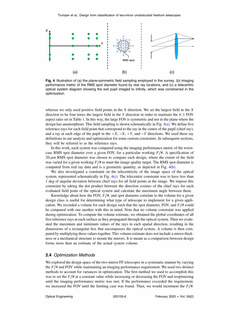
whereas we only used positive field points in the X direction. We set the largest field in the Xdirection to be four times the largest field in the Y direction in order to maintain the 4∶1 FOVaspect ratio set in Table 1. In this way, the large FOV is symmetric and not in the plane where thedesign has anamorphism. This field sampling is shown schematically in Fig. 4(a). We define fivereference rays for each field point that correspond to the ray in the center of the pupil (chief ray),and a ray at each edge of the pupil in the þX, −X, þY, and −Y directions. We used these raydefinitions in our analysis and optimization for some custom constraints. In subsequent sections,they will be referred to as the reference rays.
In this work, each system was compared using the imaging performance metric of the worst-case RMS spot diameter over a given FOV, for a particular working F∕#. A specification of20-μm RMS spot diameter was chosen to compare each design, where the extent of the fieldwas varied for a given working F∕# to meet the image quality target. The RMS spot diameter iscomputed from real ray data and is a geometric quantity, as depicted in Fig. 4(b).
We also investigated a constraint on the telecentricity of the image space of the opticalsystem, represented schematically in Fig. 4(c). The telecentric constraint was to have less than1 deg of angular deviation between chief rays for all field points at the image. We impose thisconstraint by taking the dot product between the direction cosines of the chief rays for eachevaluated field point of the optical system and calculate the maximum angle between them.
Knowledge about how the FOV, F∕#, and spot diameter correlate to the volume for a givendesign class is useful for determining what type of telescope to implement for a given appli-cation. We recorded a volume for each design such that the spot diameter, FOV, and F∕# couldbe compared with one another with this in mind. Note that no volume constraint was appliedduring optimization. To compute the volume estimate, we obtained the global coordinates of allfive reference rays at each surface as they propagated through the optical system. Then we evalu-ated the maximum and minimum values of the rays in each spatial direction, resulting in thedimensions of a rectangular box that encompasses the optical system. A volume is then com-puted by multiplying these values together. This volume estimate does not include a mirror thick-ness or a mechanical structure to mount the mirrors. It is meant as a comparison between designforms more than an estimate of the actual system volume.
2.4 Optimization Methods
We explored the design space of the two-mirror FF telescopes in a systematic manner by varyingthe F∕# and FOV while maintaining an imaging performance requirement. We used two distinctmethods to account for variances in optimization. The first method we used to accomplish thiswas to set the F∕# at a constant value while increasing or decreasing the FOVand reoptimizinguntil the imaging performance metric was met. If the performance exceeded the requirement,we increased the FOV until the limiting case was found. Then, we would increment the F∕#.
Fig. 4 Illustration of (a) the plane-symmetric field sampling employed in the survey, (b) imagingperformance metric of the RMS spot diameter found by real ray locations, and (c) a telecentricoptical system diagram showing the exit pupil imaged to infinity, which was constrained in theoptimization.
Trumper et al.: Design form classification of two-mirror unobstructed freeform telescopes
Optical Engineering 025105-6 February 2020 • Vol. 59(2)

To generate a smooth enough curve while being efficient, we generally implemented an F∕# stepsize between 0.25 and 0.5. For designs that were unstable during optimization, we loweredthe step size but, in general, the FF designs were able to accommodate large jumps in both theFOV and F∕# and still optimize well. The other method we used samples the FOV in specificintervals and iterates the F∕# along with optimization to meet the imaging requirement. For thismethod, we used an FOV step size of approximately 1 deg. Similar to the first method of explor-ing, the designs were generally amicable to large jumps in FOVand F∕#. Throughout the survey,we used both styles and garnered equivalent results. At the start of the survey, to test thatour methods were sound, we used the same starting point design to explore a space and endedup with nearly identical results. We attribute this to the fact that the two-mirror design space issmall enough such that any reasonably thorough method of optimization will result in the samedesign.
2.5 Baseline Comparison
We designed an optical system that uses purely RS surfaces under the same constraints as the FFsystems such that we could directly compare the FOV, F∕#, spot size, and volume. The RSsystem is of a Cassegrain-like form, with a positive powered primary mirror. We imposed acommon axis of rotational symmetry on the system, but to meet the unobscured requirement,we allowed off-axis sections of the mirrors and a field bias or tilt of the first surface. To make surethat we were comparing the RS designs to the FF designs fairly, we allowed the image plane totilt as well. The surfaces used are general aspheres, where we utilized up to 10th-order poly-nomials. Both nontelecentric RS optical systems and telecentric systems are reported.
3 Telescope Design Form Classification Using Folding Direction
The design space encompassed by the systems we investigated is vast. The sheer number ofvariables in an FF optical system can create a confusing, chaotic, and difficult-to-explain design.However, we found that amid a haze of data and parameters, two main design forms shonethrough. The distinguishing feature we use to classify the two-mirror unobstructed FF telescopesinvestigated in this work is the folding direction created with the secondary mirror. This clas-sification uses the system geometry to distill and categorize the traits of an FF optical design inan elegant and intuitive way. In this manner, a visual and obvious feature of the system isemployed to gain intuition around the optical performance.
Classification methods employed in axially symmetric design spaces are typically focused onthe optical power and its grouping throughout the design. However, we find that the power of themirrors correlates strongly with the folding direction but is not as significant of a classifyingfactor. Therefore, we include this as a secondary distinction.
3.1 Two Design Forms: Type 4 and Type Z
We define a central ray, or base ray, which passes through the center of the field and pupil inthe plane of symmetry. This ray is used to specify the geometry in the optical system, such thatthe mirrors are centered on this ray and their tilts are taken about the base ray intersection pointor basal point of the mirror. All tilts in the system are about the X axis, such that the system canbe viewed accurately by looking at a projection into the YZ plane. A 0-deg tilt corresponds tothe surface normal aligned to the base ray (from the previous surface) at the basal point. For ageneral two-mirror telescope, there are two distinct folding directions to achieve an unob-structed design. These two forms are illustrated in Fig. 5. We differentiate between theseforms by the sign of the tilt angle on the secondary mirror. The sign convention employedhere is that a positive angle corresponds to a counter-clockwise rotation while a negative angledescribes a clockwise rotation. Only positive tilts on the first mirror are required due tosymmetry.
When the secondary mirror is tilted about the X axis by a positive angle with respect to thebasal point, we achieve a geometry where the light is folded back toward the incoming beam
Trumper et al.: Design form classification of two-mirror unobstructed freeform telescopes
Optical Engineering 025105-7 February 2020 • Vol. 59(2)

path. To achieve an unobstructed design, this typically means the image plane is placed on the farside of the incident beam from the secondary. In this configuration, the design resembles thenumeral 4, hence we have termed it a “type 4” form, representing the positive sign of the tiltangle about the X axis for each mirror. In the case that the secondary has a negative folding angle,opposite from the type 4 case, the light is reflected in the same general direction as the incomingbeam. In this layout, it closely resembles the letter Z, which inspired the naming of “type Z.”Figure 6 shows the two-dimensional cross sections (in the plane of symmetry) of nine repre-sentative designs selected from this work, highlighting the diversity of design forms in thissolution space.
Prescriptions for a type Z, type 4, and RS design at F∕5, which are representative of howthe survey systems were defined, are given in tabular form in Sec. 6 for reference.
Fig. 6 Design categories of two-mirror FF telescopes sampled at three representative F∕#s toprovide a general design layout insight for each category and a visual estimate of the volumeof the optical system.
Fig. 5 Illustration of the two design forms used to categorize the two-mirror FF design space(a) type 4, and (b) type Z. The type 4 design form uses only positive tilts about the x axis, whereasthe type Z design form has a negative tilt on the second mirror.
Trumper et al.: Design form classification of two-mirror unobstructed freeform telescopes
Optical Engineering 025105-8 February 2020 • Vol. 59(2)

4 Optical Performance Analysis and Evaluation
4.1 Trade-off Space between Field of View and F/#
Important optical specifications such as FOV, F∕#, and system volume are affected by the choiceof design form. We report the relationship found between these three characteristics for the twoclassifications of two-mirror FF telescopes we investigated. A FOV versus F∕# curve is gener-ated, similar to a bubble diagram shown in many optical design texts,26 which is shown in Fig. 7.This curve allows optical engineers and scientists to quickly downselect and decide if a baselinedesign form, such as the type 4 or type Z, is worth investigating for a specific application.
For a nontelecentric optical system, the type Z design achieves the largest FOV for all F∕#scompared to the type 4 and RS baseline. In the telecentric case, at F∕#s greater than F∕4.5, thetype 4 design performs better than the type Z, whereas for smaller F∕#s, they perform similarly.The type 4 design form also obtains a larger FOV than the RS baseline system for both a tele-centric and nontelecentric case, highlighting the benefits of utilizing an FF surface in opticaldesign of off-axis unobstructed systems. In the nontelecentric case, the type 4 and type Z designforms follow an approximately parabolic relationship between the FOVand F∕# for a fixed spotdiameter imaging requirement. The relationship in the telecentric case is not quite as clear, wherean inflection point was found around F∕5 for both design forms.
4.2 Trade-off Space between Volume and F/#
When we examine the volume of the system versus F∕#, which can be a critical parameter forspace-based telescopes, the type Z design has a significantly larger spatial extent than all otherdesign forms, as shown in Fig. 8.
A strong trade-off between optical performance and volume exists for the type Z design form.When a telecentric constraint is imposed, the volume is reduced to a more manageable size, butthe performance difference between the type 4 and type Z is also minimal. The type 4 designform maintains a smaller volume than the RS design while achieving a better FOV.
4.3 Discussion of the Field of View and Volume for the Two Design Forms
The type Z system closely resembles a Schwarzschild design, which has a negative-poweredprimary mirror and a large positive-powered secondary. This design form is well known for
Fig. 7 FFOV in the direction of symmetry (X) versus F∕# for the various design forms andtelecentricity constraints investigated in this survey. Solid lines denote the telecentric systems(<1 deg deviation between chief ray angles at image plane), and dashed lines refer to no tele-centricity constraint. The type Z design form provides significantly superior optical performance(FOV and F∕#) compared to the RS, type 4, and type Z in the nontelecentric case.
Trumper et al.: Design form classification of two-mirror unobstructed freeform telescopes
Optical Engineering 025105-9 February 2020 • Vol. 59(2)

obtaining large FOVs,6,27 which is exactly the behavior we observe in the FF design. When twopositive-powered mirrors are used to form an image, the Petzval field curvature degrades imagequality rapidly with field angle. With a negative primary, it is able to balance the Petzval, andtherefore maintain image quality for larger FOVs. The downside with this approach is that thesecondary mirror diameter must increase to accept the light reflected off of the negative primary.Therefore, the Schwarzschild-like designs suffer from large volumes as we see in the type Zdesign. A Schwarzschild-like design for the type 4 geometry is not as beneficial because thepositive tilt angle of the secondary creates larger angles of incidence on the mirror, whichincreases the magnitude of the aberrations. Therefore, a type 4 design form that tries to balancethe Petzval creates more problems in the form of other aberrations.
4.4 Telecentric versus Nontelecentric System Design
Comparing a telecentric with a nontelecentric design, within the same design form, the tele-centric FF systems do not achieve as large FOVs for any F∕#. The telecentric FF systems dohave smaller volumes for a majority of F∕#s compared to the nontelecentric designs. This isbecause the entrance pupil wants to be close to the first mirror. When the telecentricity constraintis released, the entrance pupil shifts away from the mirrors, which results in a larger volume,as shown in Fig. 8.
A unique feature about the telecentric systems is that for large F∕#s, the type 4 design per-forms better and has a smaller volume than the type Z design form, whereas at small F∕#s, thetype Z design performs slightly better, although it has a larger volume. This crossover behavioris explained by the type 4’s change of design space. At small F∕#s, the tilts of the primaryand secondary mirrors are small, but at large F∕#s, the tilt of the primary mirror increasessignificantly.
4.5 Two-Mirror versus Three-Mirror Telescope Solution Spaces
In general, the three-mirror designs that have been surveyed previously can achieve better opticalperformance (spot size, FOV, distortion, etc.) at the expense of another optical surface. This leadsto typically larger volumes and more complex fabrication and testing. For this reason, choosingthe appropriate design form has more impacts than just optical and should be carefully evaluated.
Fig. 8 Plot of the system volume in log-space versus F∕# for all types of two-mirror FF telescopesinvestigated in this work. Solid lines denote the telecentric systems (<1 deg deviation betweenchief ray angles at image plane), and dashed lines refer to no telecentricity constraint. Note thatthe FOV varies as a function of F∕#. While the type Z obtains the largest FOV, it comes at the costof system volume. The type 4 design form is a more balanced optical configuration, performingsignificantly better than its RS counterpart while keeping the same or smaller volume.
Trumper et al.: Design form classification of two-mirror unobstructed freeform telescopes
Optical Engineering 025105-10 February 2020 • Vol. 59(2)

5 Concluding Remarks
In the application space of two-mirror, unobstructed, plane-symmetric FF telescopes with the objectat infinity, there exists two distinguished main design forms: type 4 and type Z. Each design formhas trade-offs, where the type Z can achieve very large FOVs, but its system volume is also large.Furthermore, FF surfaces show a significant improvement in the achieved FOVover RS surfaces.
As the F∕# decreases to a value of 2, the volumes of both design forms converge. This isbecause the EFL of the optical system becomes a significant fraction, one-half, of the entrancepupil. Therefore, the rays must be focused quickly, which brings the mirrors closer together andreduces the total volume of the optical system.
While optimizing each system, we noted the following characteristics. A telecentricity con-straint generally made the optimization less stable for both design forms, but especially for thetype Z geometry. The other significant trend that we noticed was that the imaging performance ofthe design often decreased when an X–Y polynomial order of greater than 6 or 7 was used. Webelieve that this is a software issue, where the optimizer is not set up properly to control so manypolynomial terms. Therefore, when all the coefficients up to 10th order are allowed to vary,the optimizer actually walks away from the minimum.
Further work in the area of surveying the design solution space for two-mirror plane-symmetric FF telescopes is still needed. The manufacturability of the surfaces, the imaging per-formance as a function of FOV and/or volume, and evaluation of different surface equations/parameters are all potent and important avenues to explore. The multitude of constraints andconsiderations for various applications of an optical system leave much work for opticaldesigners looking to find a good starting design form.
6 Appendix A
Prescriptions for an RS (Table 2), type Z (Table 3), and type 4 (Table 4) design at F∕5, which arerepresentative of how the survey systems were defined in this study, are given in tabular form forreference. The tables contain the type of each surface, a label, and the optical parameters neededto recreate the system. Thicknesses are with respect to the previous surface, and any parameteromitted is zero. All length units are in millimeters and angle units are in degrees.
6.1 F/5 Rotationally Symmetric Design Prescription
Table 2 F∕5 RS design prescription.
Surface Surface type Radius Conic Thickness
Object N.A. 0 0 Inf.
Stop Sphere 0 0 608.72
M1 Asphere −4573.12 606.6 −489.35
M2 Asphere 444.97 −1.7 177.66
Image Sphere 0 0 N.A.
Asphere coefficients
Order 4th 6th 8th 10th
M1 2.14E-09 −7.93E-14 7.66E-18 −2.36E-22
M2 2.31E-09 1.43E-15 −6.39E-20 1.14E-24
Decenters/tilts
X Y Z Alpha Beta Gamma
M1 0 0 0 19.96 0 0
M2 0 0 0 0 0 0
Image 0 0 0 24.51 0 0
Trumper et al.: Design form classification of two-mirror unobstructed freeform telescopes
Optical Engineering 025105-11 February 2020 • Vol. 59(2)

6.2 F/5 Type Z Design Prescription
Table 3 F∕5 type Z design prescription.
Surface Surface type Radius Conic Thickness
Object N.A. 0 0 Inf.
Stop Sphere 0 0 351.46
M1 X–Y polynomial 0 0 −139.88
M2 X–Y polynomial 0 0 196.82
Image Sphere 0 0 N.A.
X–Y polynomial coefficients
M1 x2 y2 x2y y3 x4 x2y2
−0.00048 −3.09E-04 4.21E-07 2.79E-07 7.12E-10 −1.97E-10
y4 x4y x2y3 y5 x6 x4y2
−1.08E-09 1.83E-11 2.99E-12 1.81E-12 −2.59E-13 −8.44E-13
x2y4 y6 x6y x4y3 x2y5 y7
−5.75E-14 8.27E-13 −4.54E-15 5.70E-15 5.61E-16 −9.09E-16
x8 x6y2 x4y4 x2y6 y8 x8y
5.99E-17 2.18E-16 1.31E-16 −6.71E-17 −3.15E-16 6.67E-19
x6y3 x4y5 x2y7 y9 x10 x8y2
−9.20E-19 −4.51E-19 2.04E-19 2.08E-19 −3.66E-21 −1.20E-20
x6y4 x4y6 x2y8 y10 — —
−2.51E-20 −4.79E-21 1.85E-20 4.39E-20 — —
M2 x2 y2 x2y y3 x4 x2y2
0.000837 0.000723 1.50E-06 1.32E-06 1.95E-09 2.39E-09
y4 x4y x2y3 y5 x6 x4y2
2.46E-10 4.22E-11 1.50E-11 6.31E-12 −2.87E-13 −1.28E-12
x2y4 y6 x6y x4y3 x2y5 y7
−2.54E-13 2.48E-12 −9.84E-15 8.10E-15 −2.16E-15 −2.33E-15
x8 x6y2 x4y4 x2y6 y8 x8y
4.70E-17 2.40E-16 2.90E-16 −1.92E-16 −1.61E-15 1.04E-18
x6y3 x4y5 x2y7 y9 x10 x8y2
−1.52E-18 −6.21E-20 1.20E-18 5.77E-19 −2.15E-21 −8.38E-21
x6y4 x4y6 x2y8 y10 — —
−4.72E-20 2.48E-21 6.68E-20 3.78E-19 — —
Decenters/tilts
X Y Z Alpha Beta Gamma
M1 0 0 0 36.64 0 0
M2 0 0 0 21.79 0 0
Image 0 0 0 4.07 0 0
Trumper et al.: Design form classification of two-mirror unobstructed freeform telescopes
Optical Engineering 025105-12 February 2020 • Vol. 59(2)

6.3 F/5 Type 4 Design Prescription
Acknowledgments
The authors would like to acknowledge the support of the II-VI Foundation, and the employeesand mentors at Goddard Space Flight Center who helped and guided this design space inves-tigation project. The authors have no competing interests to declare.
References
1. J. Bentley and C. Olson, Field Guide to Lens Design, SPIE Press, Bellingham, Washington(2012).
2. R. R. Shannon, The Art and Science of Optical Design, Cambridge University Press,Cambridge (1997).
3. C. L. Wyman and D. Korsch, “Aplanatic two-mirror telescopes: a systematic study. 1:Cassegrainian configuration,” Appl. Opt. 13, 2064–2066 (1974).
Table 4 F∕5 type 4 design prescription.
Surface Surface type Radius Conic Thickness
Object N.A. 0 0 Inf.
Stop Sphere 0 0 57.08
M1 X–Y polynomial 0 0 −504.02
M2 X–Y polynomial 0 0 571.34
Image Sphere 0 0 N.A.
X–Y polynomial coefficients
M1 x2 y2 x2y y3 x4 x2y2
0.000767011 5.19E-04 −5.89E-07 −4.14E-07 2.94E-09 3.77E-09
y4 x4y x2y3 y5 x6 x4y2
1.77E-09 −3.43E-11 −3.11E-11 −2.94E-12 −1.65E-13 −3.29E-14
x2y4 y6 x6y x4y3 x2y5 y7
3.49E-15 −6.18E-14 6.57E-15 1.13E-14 3.10E-15 −1.17E-15
M2 x2 y2 x2y y3 x4 x2y2
0.000719818 0.000711 −1.24E-07 −1.22E-07 4.08E-10 8.56E-10
y4 x4y x2y3 y5 x6 x4y2
4.43E-10 −2.29E-13 −4.56E-13 −2.53E-13 5.92E-16 1.92E-15
x2y4 y6 x6y x4y3 x2y5 y7
2.09E-15 7.51E-16 −7.75E-19 −2.85E-18 −1.84E-18 −1.42E-18
Decenters/tilts
X Y Z Alpha Beta Gamma
M1 0 0 0 34.51 0 0
M2 0 0 0 −6.3 0 0
Image 0 0 0 −27.27 0 0
Trumper et al.: Design form classification of two-mirror unobstructed freeform telescopes
Optical Engineering 025105-13 February 2020 • Vol. 59(2)
4. C. L. Wyman and D. Korsch, “Systematic study of aplanatic two-mirror telescopes. 2:The Gregorian configuration,” Appl. Opt. 13, 2402–2404 (1974).
5. C. L. Wyman and D. Korsch, “Aplanatic two-mirror telescopes; a systematic study. 3:The Schwarzschild–Couder configuration,” Appl. Opt. 14, 992–995 (1975).
6. W. B. Wetherell and M. P. Rimmer, “General analysis of Aplanatic Cassegrain, Gregorian,and Schwarzschild telescopes,” Appl. Opt. 11, 2817–2832 (1972).
7. K. P. Thompson and J. P. Rolland, “Freeform optical surfaces: a revolution in imagingoptical design,” Opt. Photonics News 23(6), 30–35 (2012).
8. A. Bauer, E. M. Schiesser, and J. P. Rolland, “Starting geometry creation and design methodfor freeform optics,” Nat. Commun. 9, 1756 (2018).
9. J. C. Papa, J. M. Howard, and J. P. Rolland, “Three-mirror freeform imagers,” Proc. SPIE10690, 106901D (2018).
10. J. C. Papa, J. M. Howard, and J. P. Rolland, “Starting point designs for freeform four-mirrorsystems,” Opt. Eng. 57(10), 101705 (2018).
11. B. D. Stone and G. W. Forbes, “Foundations of first-order layout for asymmetric systems:an application of Hamilton’s methods,” J. Opt. Soc. Am. A 9, 96–109 (1992).
12. J.-B. Volatier and G. Druart, “Differential method for freeform optics applied to two-mirroroff-axis telescope design,” Opt. Lett. 44(5), 1174–1177 (2019).
13. B. D. Stone and G. W. Forbes, “Characterization of first-order optical properties forasymmetric systems,” J. Opt. Soc. Am. A 9, 478–489 (1992).
14. B. D. Stone and G. W. Forbes, “Foundations of second-order layout for asymmetricsystems,” J. Opt. Soc. Am. A 9, 2067–2082 (1992).
15. B. D. Stone and G. W. Forbes, “Second-order design methods for definitive studies of plane-symmetric, two-mirror systems,” J. Opt. Soc. Am. A 11, 3292–3307 (1994).
16. L. B. Moore, A. M. Hvisc, and J. Sasian, “Aberration fields of a combination of planesymmetric systems,” Opt. Express 16, 15655–15670 (2008).
17. K. P. Thompson, “Description of the third-order optical aberrations of near-circular pupiloptical systems without symmetry,” J. Opt. Soc. Am. A 22, 1389–1401 (2005).
18. K. Fuerschbach, J. P. Rolland, and K. P. Thompson, “Theory of aberration fields forgeneral optical systems with freeform surfaces,” Opt. Express 22(22), 26585–26606(2014).
19. B. D. Stone and J. M. Howard, “Low-order aberration coefficients applied to design oftelescopes with freeform surfaces,” Proc. SPIE 10562, 1056229 (2017).
20. B. Ma et al., “Applying slope constrained Q-type aspheres to develop higher performancelenses,” Opt. Express 19, 21174–21179 (2011).
21. N. Takaki, A. Bauer, and J. P. Rolland, “On-the-fly surface manufacturability constraints forfreeform optical design enabled by orthogonal polynomials,” Opt. Express 27, 6129–6146(2019).
22. G. W. Forbes, “Characterizing the shape of freeform optics,” Opt. Express 20, 2483–2499(2012).
23. J. M. Howard, “Optical design using computer graphics,” Appl. Opt. 40, 3225–3231 (2001).24. J. M. Howard, “Optical design tools for reflective optical systems,” Proc. SPIE 4849,
407–412 (2002)25. J. M. Howard, “SLIDERS: the next generation of automated optical design tools has
arrived,” Proc. SPIE 5174, 19–25 (2003).26. W. J. Smith, Modern Lens Design, McGraw-Hill, New York (2005).27. J. M. Sasian, “Design of a Schwarzschild flat-field, anastigmatic, unobstructed, wide-field
telescope,” Opt. Eng. 29(1), 1–5 (1990).
Isaac Trumper received his PhD from the University of Arizona, focusing on software tools forfreeform metrology, design, and analysis. He is now CTO at ELE Optics, developing the nextgeneration of software for light-based technology.
Alexander Q. Anderson received his BS degree in optical engineering from University ofRochester and is currently a PhD student at University of Colorado Boulder. His current researchinterests include remote sensing, structured illumination, and orbital angular momentum.
Trumper et al.: Design form classification of two-mirror unobstructed freeform telescopes
Optical Engineering 025105-14 February 2020 • Vol. 59(2)

Joseph M. Howard received a BS degree in physics from the US Naval Academy in Annapolis,Maryland, and his PhD in optical design from The Institute of Optics, University of Rochester,in Rochester, New York. He now serves as an optical designer for NASA, working on projectsincluding the James Webb Space Telescope and the other future space missions.
Garrett West is a senior optical engineer and optical designer at Ball Aerospace in Boulder, CO.He designs and analyzes the next generation of space optical instruments and telescopes.He is optical engineering experience spans from small internal research efforts to large interna-tional missions, such as the James Webb Space Telescope. His research focus is in freeformoptics, where he investigates designs with reduced volume, fewer mirrors, wider fields of view,and better image quality to meet the growing needs of aerospace missions.
Dae Wook Kim is an assistant professor of optical sciences and astronomy at the University ofArizona. His research area covers precision optical engineering, including interferometry anddeflectometry. He is the chair of the Optical Manufacturing and Testing (SPIE) and OpticalFabrication and Testing (OSA) conferences. He is a senior member of OSA and SPIE and hasserved as an associate editor for the OSA Optics Express journal.
Trumper et al.: Design form classification of two-mirror unobstructed freeform telescopes
Optical Engineering 025105-15 February 2020 • Vol. 59(2)