design guidance for diversity factors for ambient
TRANSCRIPT

September 2021
Design Guidance for Diversity Factors for Ambient Temperature Networks using the Zeroth Energy SystemZeroth Heat Pump Application Guide created by Wallace Whittle in
collaboration with TÜV SÜD for Glen Dimplex Heating & Ventilation
In collaboration with

Wallace Whittle aim to be the pre-eminent provider of quality building services solutions and the best to work with, in the view of our clients, partners and colleagues. We believe in a sustainability led approach to design for the benefit of our clients and the world we live in. It is our ultimate goal to work closely with our fellow professionals and clients to minimise carbon emissions and to deliver a better environment for us all to live in.
Glen Dimplex Heating & Ventilation
At Glen Dimplex Heating & Ventilation (GDHV), we are dedicated to the design and development of sustainable HVAC solutions for both commercial and residential projects. We offer multiple brands in combined solutions for the new build and refurbishment markets.
We believe the future of HVAC lies in product innovation which contributes to a sustainable, zero carbon future, and we are devoted to investment in low carbon technologies which meet the needs of industry and its customers.
22 About Us
TÜV SÜD is a trusted partner of choice for safety, security, and sustainability solutions. Over the last 150 years, TÜV SÜD add value to our partners and customers through a comprehensive portfolio of testing, certification, auditing, and advisory services. Wallace Whittle is a Cooperation Partner of TÜV SÜD.
In collaboration with

Contents
1.0 Overview
1.1 Recognisingthelimitationsofcurrentcommunalheatingsystems . . . . . . . . . . . . . . . . 4
1.2 Calculatingtheheatlossfromaheatingnetwork . . . . . . . . . . . . . . . . . . . . . . . . . . . . . . . 5
1.3 UnderstandingthebenefitsofanambientloopandtheZerothEnergySystem . . . . 7
2.0 Design Guide
2 .1 Design Criteria for the Ambient Loop . . . . . . . . . . . . . . . . . . . . . . . . . . . . . . . . . . . . . . . . . . 8
2.2 DwellingLoadsandSelectionoftheZerothHeatPump . . . . . . . . . . . . . . . . . . . . . . . .12
2.3 ApplicationofDiversity . . . . . . . . . . . . . . . . . . . . . . . . . . . . . . . . . . . . . . . . . . . . . . . . . . . . . .13
2.4 SizingaZerothHeatPumpDistributionSystem . . . . . . . . . . . . . . . . . . . . . . . . . . . . . . . .17
2 .5 Worked Example . . . . . . . . . . . . . . . . . . . . . . . . . . . . . . . . . . . . . . . . . . . . . . . . . . . . . . . . . . . .18
3.0 Glossary of Terms and Acronyms . . . . . . . . . . . . . . . . . . . . . . . . . . . . . . . . . . . . . . . . . .22
4.0 References . . . . . . . . . . . . . . . . . . . . . . . . . . . . . . . . . . . . . . . . . . . . . . . . . . . . . . . . . . . . . . . . .23
Appendices
Appendix1ERPProfiles . . . . . . . . . . . . . . . . . . . . . . . . . . . . . . . . . . . . . . . . . . . . . . . . . . . . . . . . . . .24
Appendix2ComparisonofHWCs&HIUs-DecouplingDemand . . . . . . . . . . . . . . . . . . . . . .26
Appendix3ZerothPipeworkSystems . . . . . . . . . . . . . . . . . . . . . . . . . . . . . . . . . . . . . . . . . . . . . . .27
Appendix4GuidanceonBufferVesselsorThermalStorageVessels . . . . . . . . . . . . . . . . . . .31
Appendix 5 Metering Requirements . . . . . . . . . . . . . . . . . . . . . . . . . . . . . . . . . . . . . . . . . . . . . . . . .31
Appendix6HeatingandCooling . . . . . . . . . . . . . . . . . . . . . . . . . . . . . . . . . . . . . . . . . . . . . . . . . . . .32
Appendix7Heating . . . . . . . . . . . . . . . . . . . . . . . . . . . . . . . . . . . . . . . . . . . . . . . . . . . . . . . . . . . . . . .32
3 Contents

1.0 Overview■ The purpose of this document is to provide a design guide to assist in the implementation of a Zeroth Energy System in a new
development. The target audience is the mechanical design engineer; however, it is anticipated that developers and architects will also find it informative.
1.1 Recognising the limitations of current communal heating systems
■ A traditional communal heating system is typically served by central boilers with in-apartment heat interface units (HIUs), used for heating and hot water services. It uses a central water loop typically circulating at high temperatures of circa 80-60⁰C or 70-40⁰C for heat networks, or 6-12⁰C for chilled water networks.
■ A traditional communal heating system’s design performance decreases as the energy performance of a building increases. This is because, as demand falls, losses become a greater proportion of the total energy supplied to the building.
■ The simple explanation for this reduction in performance is due to the temperature difference between the pipe and its external ambient. This basic relationship is explained using the heat transfer formula:
kW=ṁ* Cp *∆T Where kW is the kilowatt of heat, ṁ is the mass, Сp is the specific heat capacity of water and ∆T is the temperature difference
between the pipe surface and the surrounding air.
■ Therefore, if we consider a pipe within a building riser, corridor or plant room, the closer the pipe temperature is to ambient, the smaller the temperature difference and therefore the lower the heat transfer rate from that pipe.
■ In traditional designs, insulation is applied to the pipework to reduce its surface temperature, reducing the temperature difference with ambient and hence reducing the losses. Unfortunately, this approach has two limiting factors:
➤ The insulation thickness applied will be limited by economic or spatial concerns.
➤ The temperature within the network is fixed to serve a specific purpose, for example to serve hot water needs.
■ One of the outstanding issues with current heating or cooling design practice is that heat losses or gains on the network can be reduced, but not completely eradicated.
■ Historically these losses have been an accepted part of the design and the annual efficiency of traditional systems have remained within tolerances that are deemed to be acceptable. However, as we have improved the thermal performance of our buildings for compliance purposes, the demand for energy has been substantially reduced. The net result is that when the same design is implemented within a thermally efficient building, the system efficiency is substantially reduced when compared with a less thermally efficient building.
■ This is simply because the losses, despite staying the same, have become a greater total proportion of the overall energy consumed by the network. For example:
➤ A building with a thermal demand of 500,000kWh and losses of 100,000kWh will have a network efficiency of 83%.
➤ If this building was thermally improved and reduced its demand to 150,000kWh and the losses stayed the same, the network efficiency would drop to 60%.
■ An undesirable effect of low system efficiency in a thermally efficient building is that losses actually meet 66% of the buildings total thermal requirement for the year. This extra energy is not required and the net result is an increase in the air temperature within the building.
■ The improved envelope of modern compliant buildings makes it more difficult to remove this heat, increasing the internal air temperature of the building. This exacerbates overheating problems within the building corridors and subsequently the apartment spaces adjacent to them.
■ In response to these increasing summer temperatures, engineers are currently specifying cooling systems, increasing the energy consumption of the building further and also increasing the build and running costs to meet thermal comfort requirements.
4 1.0 Overview

1.2 Calculating the heat loss from a heating network
■ Building Service Engineers tend to use rules of thumb when it comes to allowing for the additional heating capacity needed to overcome network losses. Typically, this is applied as an overload factor of 10-15% on top of the calculated heating requirement. ISO 12241 “Thermal insulation for building equipment and industrial installations – calculation rules” provides a more comprehensive method, which takes into account a number of environmental and design variables including:
➤ Pipe diameter ➤ Pipe length ➤ Distribution temperatures ➤ Air temperature surrounding the pipe ➤ Air velocity surrounding the pipe ➤ Emissivity of insulation ➤ Thickness of insulation ➤ Thermal conductivity of the insulation (k value)
5 1.0 Overview

■ Using the ISO 12241 standard, the average linear heat loss (watts per meter) within the network temperature can be established. For example:
➤ Take a 55 apartment building fed by central boilers with heat interface units (HIUs), used for heating and hot water services.
➤ The boiler size, based on the CIBSE Code of Practice, would be approximately 360kW to meet the instantaneous domestic hot water (DHW) and heating requirement.
➤ The distribution system would be approximately 880m for the heating network and standard rule of thumb losses would be approximately 35kW, yielding a boiler size of 400 kW.
➤ The table below shows the calculated operational losses for the same network, with the same level of pipework insulation.
Table 1: Network loss calculations from Glen Dimplex Heating & Ventilation 2016
■ Table 1 demonstrates that for a typical design the 10-15% rule substantially overestimates the network losses with calculated losses actually closer to 8kW instead of 35kW. The table also shows that as network temperature decreases, the network losses also reduce.
■ For a typical traditional design of 70-40⁰C the losses would in reality vary between 7.38 and 5.38kW across the network. It is also important to consider the operational characteristics of the network and the likely energy lost per year. For example:
➤ If the system was operated 365 days per year for 24 hours per day the energy lost would be approximately 64,648kWh (365*24*7.38).
■ In summary, adopting a traditional system in a thermally efficient compliant building will result in increased energy use, carbon emissions and exacerbated overheating problems within the corridors and subsequently the apartment spaces adjacent to them. This approach would also miss an opportunity to take advantage of the efficiency of modern heat pump technology, enabling electrification and the decarbonisation of heat in buildings that regulations are moving quickly towards.
6 1.0 Overview
Flow Return[°C] DeltaT Networkheat AverageWatts [°C] [°C] T loss [kW] per meter loss 80 80 0 8 .72 9 .88 80 70 10 8 .05 9 .12 80 60 20 7 .38 8 .37 80 50 30 6 .71 7 .61 70 70 0 7 .38 8 .36 70 60 10 6 .71 7 .61 70 50 20 6 .04 6 .85 70 40 30 5 .38 6 .10 60 60 0 6 .04 6 .85 60 50 10 5 .37 6 .09 60 40 20 4 .71 5 .34 60 30 30 4 .05 4 .59 50 50 0 4 .71 5 .34 50 40 10 4 .04 4 .58 50 30 20 3 .38 3 .84 50 20 30 2 .73 3 .10 40 40 0 3 .38 3 .83 40 30 10 2 .72 3 .08 40 20 20 2 .07 2 .34 30 30 0 2 .06 2 .33 30 20 10 1 .41 1 .59 20 20 0 0 .75 0 .85 20 10 10 0 .38 0 .43

1.3 Understanding the benefits of an ambient loop and the Zeroth Energy System
■ In recognition of the limitations of current communal heating systems Glen Dimplex Heating & Ventilation have developed the Zeroth Energy System which uses an ambient loop. This approach mitigates many of the issues discussed above.
■ The system’s ambient loop is similar to traditional communal heating system designs, in that it uses water as a distribution medium and relies on pressurised plastic or steel pipework routed through the risers, floors or ceiling voids.
■ The unique feature of the ambient loop is the temperature utilised is 25⁰C, rather than 80-60⁰C or 70-40⁰C for traditional heat networks or 6-12⁰C for chilled water networks. This unique temperature is very close to ambient and therefore has not previously been usable for cooling, hot water or heating services. In order to implement this approach, a water-to-water heat pump is required to provide the necessary temperature adjustment.
■ The Zeroth Energy System provides heating, cooling and hot water services to residential spaces using a network of in-apartment water-to-water heat pumps. The heat pumps are connected to the ambient loop at 25⁰C, raising it up to, for example, 55⁰C where it is it retained in an integral cylinder for use within the apartment. Like a traditional system the ambient loop is regulated within its operating parameters using centralised heating and cooling plant.
■ The Zeroth Heat Pump in each apartment can be connected to a range of emitters including fan coils, radiators, underfloor heating or fan convectors.
■ The core benefits of adopting an ambient loop with the Zeroth Energy System include:
➤ Easier Part L compliance
➤ Easier connection to district heating networks due to low temperature requirements
➤ Increased scope for using low carbon central plant
➤ Reduced central plant requirements
➤ Reduced summertime corridor temperatures
➤ Reduced apartment overheating risk
➤ Future proofing through enabling of subsequent fifth generation heat network connection
➤ Provision of both heating, hot water and cooling services via a two-pipe network, offering capital savings over traditional four-pipe solutions
➤ Significantly improved energy performance of the thermal network, up to 90% reduction in losses when compared to traditional CHP/boiler designs with heat interface units
➤ Efficiencies up to 300% when deployed in conjunction with air source heat pumps (ASHPs) as central plant
➤ No requirement for refrigerant pipework or leak detection devices
➤ Lower running costs
➤ Carbon tax reduction
7 1.0 Overview
8 2.0 Design Guide
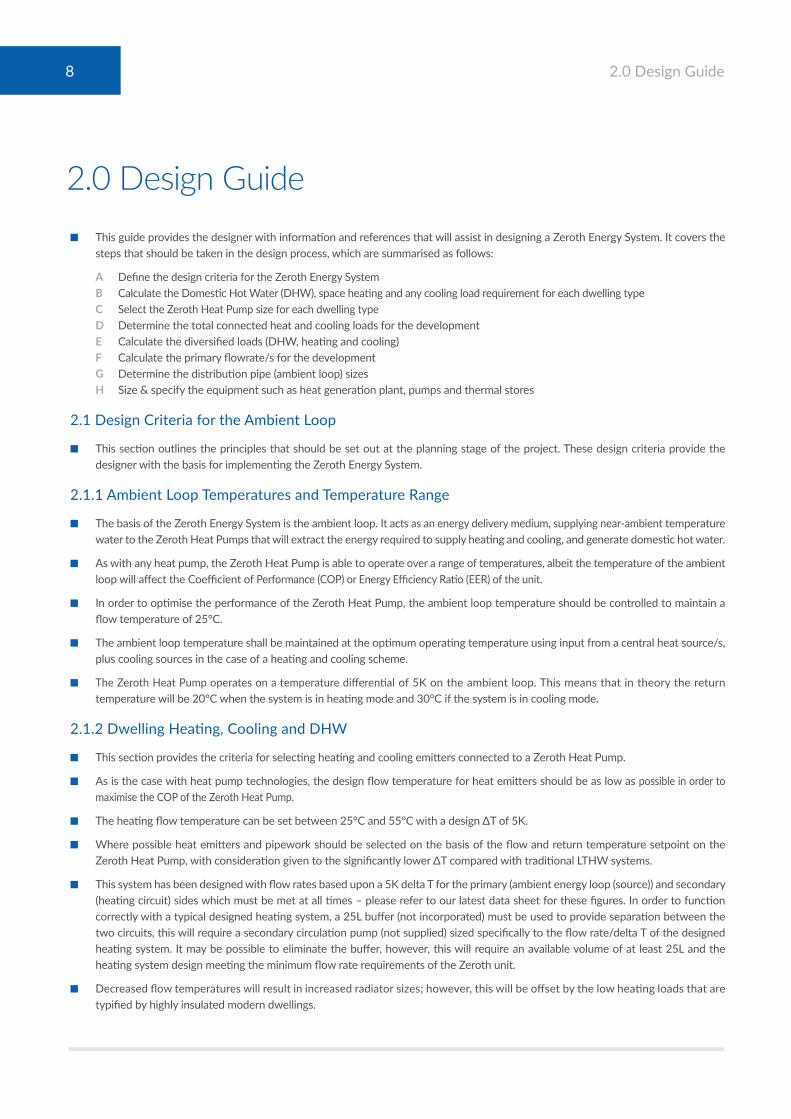
2.0 Design Guide■ This guide provides the designer with information and references that will assist in designing a Zeroth Energy System. It covers the
steps that should be taken in the design process, which are summarised as follows:
A Define the design criteria for the Zeroth Energy System B Calculate the Domestic Hot Water (DHW), space heating and any cooling load requirement for each dwelling type C Select the Zeroth Heat Pump size for each dwelling type D Determine the total connected heat and cooling loads for the development E Calculate the diversified loads (DHW, heating and cooling) F Calculate the primary flowrate/s for the development G Determine the distribution pipe (ambient loop) sizes H Size & specify the equipment such as heat generation plant, pumps and thermal stores
2.1 Design Criteria for the Ambient Loop
■ This section outlines the principles that should be set out at the planning stage of the project. These design criteria provide the designer with the basis for implementing the Zeroth Energy System.
2.1.1 Ambient Loop Temperatures and Temperature Range
■ The basis of the Zeroth Energy System is the ambient loop. It acts as an energy delivery medium, supplying near-ambient temperature water to the Zeroth Heat Pumps that will extract the energy required to supply heating and cooling, and generate domestic hot water.
■ As with any heat pump, the Zeroth Heat Pump is able to operate over a range of temperatures, albeit the temperature of the ambient loop will affect the Coefficient of Performance (COP) or Energy Efficiency Ratio (EER) of the unit.
■ In order to optimise the performance of the Zeroth Heat Pump, the ambient loop temperature should be controlled to maintain a flow temperature of 25°C.
■ The ambient loop temperature shall be maintained at the optimum operating temperature using input from a central heat source/s, plus cooling sources in the case of a heating and cooling scheme.
■ The Zeroth Heat Pump operates on a temperature differential of 5K on the ambient loop. This means that in theory the return temperature will be 20°C when the system is in heating mode and 30°C if the system is in cooling mode.
2.1.2 Dwelling Heating, Cooling and DHW
■ This section provides the criteria for selecting heating and cooling emitters connected to a Zeroth Heat Pump.
■ As is the case with heat pump technologies, the design flow temperature for heat emitters should be as low as possible in order to maximise the COP of the Zeroth Heat Pump.
■ The heating flow temperature can be set between 25°C and 55°C with a design ∆T of 5K.
■ Where possible heat emitters and pipework should be selected on the basis of the flow and return temperature setpoint on the Zeroth Heat Pump, with consideration given to the significantly lower ∆T compared with traditional LTHW systems.
■ This system has been designed with flow rates based upon a 5K delta T for the primary (ambient energy loop (source)) and secondary (heating circuit) sides which must be met at all times – please refer to our latest data sheet for these figures. In order to function correctly with a typical designed heating system, a 25L buffer (not incorporated) must be used to provide separation between the two circuits, this will require a secondary circulation pump (not supplied) sized specifically to the flow rate/delta T of the designed heating system. It may be possible to eliminate the buffer, however, this will require an available volume of at least 25L and the heating system design meeting the minimum flow rate requirements of the Zeroth unit.
■ Decreased flow temperatures will result in increased radiator sizes; however, this will be offset by the low heating loads that are typified by highly insulated modern dwellings.

■ Low temperature fan assisted radiators might be considered as a means of lowering temperatures whilst maintaining a compact size. Fan assisted radiators are a typical solution for heat pump applications.
■ Whereas other heating emitters are available, underfloor heating systems are ideally suited to the Zeroth Heat Pump output temperature to maximise efficiency because of the possibility of using lower flow temperatures.
■ The cooling flow temperature (for cooling emitters such as fan coils) can be set between 10°C and 25°C with a design ∆T of 5K.
■ When cooling is provided with fan coils, a buffer vessel should be installed into the return circuit from the cooling emitter within the dwelling. The function of this is to minimise stop-starts of the heat pump compressor. Please contact Glen Dimplex Heating & Ventilation for further information on sizing the buffer vessel.
■ The design criteria for DHW can be based on the ‘ErP’ profile or other published data. Refer to Appendices 1 and 2 for further information.
2.1.3 Heating/Cooling Mode of Operation
How much hot water does a typical dwelling use?
■ An estimate of the hot water usage is required in order to validate the storage capacity of the HWC. Useful tools for this include published research data and benchmark profiles.
■ Tapping profiles based on the ErP directive and BS EN 50440 (2015) are a useful benchmark and provide water volumes and a daily profile that can be used to determine the capacity of the HWC.
■ The Building Regulations Part G calculator is a useful tool as it requires the actual bath capacity and fittings flowrates to be specified. Along with this it provides daily water usage based on a set number of draw-offs per person.
■ NHBC Standards also provide flowrates and supply temperatures for outlets (NHBC Standards, 2020).
■ Research data is valuable as it provides measured benchmarks. One such study was the Energy Saving Trust paper, Measurement of Domestic Hot Water Consumption in Dwellings (2008). The study highlights the large variation in hot water usage between different users.
➤ Sample included 68 HWCs (fed from boilers) and 39 combi boilers ➤ The estimated mean consumption was 122 litres/day per dwelling with a 95% confidence interval of ±18 litres/day ➤ The estimated consumption per occupant was 26 ± 7 litres/day ➤ The mean delivery temperature across the whole sample was 51.9°C, estimated with a 95% confidence interval of ±1.3°C
Zeroth Heat Pump Modes of Operation
■ The Zeroth Heat Pump operates in one mode at a time; HWC reheat; space heating; or cooling (if cooling model is selected).
■ The integral control automatically sets the mode according to the demand and a set of operating parameters. Using an example to explain this, during a winter weekday morning there may be a space heating and HWC reheat demand at the same time. Assuming that the heating system is already up to the required temperature (from a preheat period set by the user), then the Zeroth Heat Pump will operate as follows:
➤ The Zeroth Heat Pump will initially be in heating mode, modulating heat output to satisfy the heating load. The minimum output that the unit can modulate down to is dependent on the operating parameters and the model, but is expected to be in the region of 2kW. If the heat load is lower than the minimum output of the Zeroth Heat Pump then the unit can cycle on and off to match the load, up to three times an hour.
➤ The Zeroth Heat Pump will always run for a minimum of 6 minutes once it is enabled, in order to minimise cycling. Whilst the unit can switch on/off up to 3 times per hour, switching between heating and HWC reheat mode can happen while the unit is continuously operating.
➤ The integral controller checks every 30mins to determine if a change of mode is required. A change of mode will occur when there is a demand for a mode other than the one currently in operation.
➤ If specified as heating and cooling, the Zeroth Heat Pump can provide simultaneous heating and cooling, but the designer should note that the Zeroth Heat Pump will switch off for 2 minutes when changing between a heating/HWC reheat mode and cooling mode.
9 2.0 Design Guide

2.1.4 Zeroth Heat Pump Controls
■ Hot water cylinder (HWC) reheat mode is automatic, this is enabled once approximately 80 litres of hot water has been drawn off. This is the default operation of the Zeroth Heat Pump. Alternatively, the unit can be set up to reheat according to pre-set times. This will require a 3rd party DHW timer/programmer that can be connected to the Zeroth unit via volt free contacts. This added functionality could, for example, be used for night time reheat, where groups of Zeroth Heat Pumps are set to reheat at different times. Generally, however, it is recommended to allow the Zeroth Heat Pump to enable HWC reheat mode under its own controls as per the default operation.
■ An electric immersion heater is installed in the HWC as a backup feature (for DHW only).
2.1.5 Zeroth Energy System Controls
■ For a heating only system, loop temperature control is as follows:
➤ The central heat source should be controlled to maintain an ambient loop flow temperature of 25°C at all times.
■ For a heating and cooling system, loop temperature shall be controlled as follows:
➤ The BMS shall determine if the system is in heating or cooling mode. This can be achieved by comparing the flow and return temperature (or temperature differential) of the ambient loop. If the return temperature is less than the flow temperature then the system is in heating mode. If the return temperature is greater than the flow temperature then the system is in cooling mode.
➤ The ambient loop flow temperature setpoint point in both heating and cooling mode is 25°C.
➤ A temperature differential setpoint should be set up to determine when a change of mode will be triggered. This value is expected to be optimised depending on the scale of the system.
➤ For example, a small system of up to 50 dwellings might have a setpoint of 5K differential to change mode, as a lower value may result in unstable operation due to temperature fluctuations, given the relatively low system volume. If, say, the system is in heating mode then the cooling mode would only activate when the return temperature reaches 30°C.
➤ A larger system of over 200 dwellings might have a setpoint of at least 1K differential to change mode, as a higher value will impact on the response time of the system. If say, the system is in cooling mode then the system would switch to heating mode when the return temperature is 24°C.
➤ It is recommended that the designer selects an initial value which will then be optimised during commissioning of the system.
■ The designer should be aware of factors that could result in the loop temperature differential being greater or less than 5K, these may include:
➤ Response time for system to react to changing loads.
➤ A combination of Zeroth Heat Pumps in heating and cooling mode.
➤ Temporary spikes in demand where the load is greater than the capacity of the central plant. These spikes can be smoothed out by the thermal capacity of the system either by the volume of water in the pipework or the use of thermal buffer tanks.
➤ If the mode in operation is satisfied within any 30min period then the unit will either switch off or change mode according to demand.
➤ The cylinder is designed to maximise stratification when not in reheat mode and can continue to provide usable hot water until the outlet temperature drops to below 40°C. The HWC can supply approximately 80 litres of hot water before the HWC reheat mode is activated. For example, the HWC reheat mode automatically starts when the water temperature at the sensor drops below 48°C; HWC reheat mode will automatically stop when the setpoint temperature of 55°C is reached.
➤ The Zeroth Heat Pump runs at 100% duty in HWC reheat mode in order to maximise hot water availability.
10 2.0 Design Guide

2.1.6 Energy Sources for the Zeroth Energy System
■ Due to the low temperature of the ambient loop, there are a large range of potential energy sources for the Zeroth Energy System which include renewable and low grade heat options in addition to the more conventional solutions. Primary heating equipment for providing heat into the ambient loop include:
➤ Air source heat pumps ➤ Ground and water source heat pumps ➤ CHP (gas, biogas, biomass) ➤ Boilers (gas, biogas, biomass) ➤ Connection to a district heating network ➤ Electric boilers ➤ Solar hot water panels
■ The range of options may be subject to a compliant Energy Strategy.
■ Further consideration might be given to the use of low grade and waste heat streams. As long as the energy source can produce heat at a greater temperature than the ambient loop, then the following examples might be viable:
➤ Data centres – emit waste heat as a bi-product of cooling servers ➤ Cold stores and supermarkets – emit waste heat as a bi-product of cooled storage rooms and refrigerated display cabinets ➤ Hotels – emit waste heat as a bi-product of cooling hotel rooms ➤ Power stations and manufacturing – emit waste heat as a bi-product of combustion ➤ Sewerage – the potential to recover waste heat from residential hot water that runs to drain ➤ Underground railway – cooling and ventilation of tunnels produces waste heat ➤ Landfill – the natural breakdown of waste produces a potentially useful heat source
■ For systems providing cooling, equipment for injecting coolth into the ambient loop include:
➤ Chillers ➤ Reversible air source heat pumps ➤ Reversible ground and water source heat pumps ➤ Cooling towers and adiabatic dry air coolers
■ Cooling towers and adiabatic dry air coolers can potentially be configured to provide free cooling. Other potential sources of free cooling could include:
➤ Rivers, lakes, seawater etc ➤ Open loop boreholes ➤ Closed loop boreholes or ground loops
■ Note that water and/or heat extracted from the ground or bodies over water will require permission from the relevant authorities, including the Environment Agency.
■ Another primary energy source for a Zeroth Energy System providing both heating and cooling is in the energy recovery from cooling and heating equipment connected to the loop. Zeroth Heat Pumps in cooling mode will provide heat into the loop that can then be used by Zeroth Heat Pumps in heating or HWC reheat mode, and vice versa.
2.1.7 Plant Selections for the Zeroth Energy System
■ Central plant should be specified to operate as efficiently as possible. Chillers and heat pumps should operate to deliver flow at or approaching 25°C, depending on how the connection to the ambient loop is made, and the operating range of the plant. For example:
➤ A chiller might be selected at 10°C/18°C flow/return which provides the best EER within the operational range for the particular unit. This would allow the chiller to be connected indirectly to the ambient loop via a plate heat exchanger if glycol is to be used in the chiller.
➤ An air source heat pump in heating mode might be selected at 35°C/30°C flow/return with a direct connection into the ambient loop.
■ Refer to Appendix 3 for information on ambient loop connection options, including plate heat exchangers.
11 2.0 Design Guide

2.2 Dwelling Loads and Selection of the Zeroth Heat Pump
■ This section provides the designer with guidance on which Zeroth Heat Pump model to select based on the calculated heating, cooling and hot water demands for an apartment.
2.2.1 Apartment DHW Usage
■ The designer should carefully consider the likely hot water usage appropriate to the dwelling. This will depend on factors such as:
➤ Number of bathrooms ➤ Number of occupants ➤ Flowrate of fittings
■ As the Zeroth Heat Pump has an integral Hot Water Cylinder (HWC), the hot water capacity is based on a usage profile rather than instantaneous load such as for Heat Interface Units (HIUs). A realistic hot water draw-off profile based on the ‘ErP’ profiles in Appendix 1 can be applied to determine the appropriate selection of Zeroth Heat Pump.
2.2.2 Heat Load
■ The heat load is calculated for the dwelling either as a steady state load or via dynamic thermal simulation; the designer should decide which is the appropriate method to apply. For apartments and attached houses the designer should allow for unheated adjacent dwellings in the heat load calculation.
■ The peak load requirement for the Zeroth Heat Pump will be during preheat period when the heating system is enabled. This can be calculated as the total installed duty of the heat emitters; however, the designer should carefully consider any margins added along with the plant size ratio. The use of design margins is outside the scope of this document; however, reference can be made to CIBSE Guide A (2016) and Guide B1 (2016). The application of plant size ratio is specifically covered in CIBSE Guide B1 (2016).
■ The steady state heat load is defined as the heat load of the dwelling under constant design winter conditions – this is used for the system sizing in Section 2.3.
■ The Zeroth Heat Pump has an inverter driven compressor so will modulate the heat output to match the heat load. The minimum output of the unit is dependent on the model and the source and output temperatures but is expected to be in the region of 2kW. If the heat load is lower than the minimum output of the Zeroth Heat Pump then the unit can cycle on and off to match the load, up to three times an hour. Note that the Zeroth Heat Pump operates in the same way in cooling mode.
2.2.3 Cooling Load
■ Dynamic thermal simulation should be carried out for the dwelling to determine the peak cooling load for each dwelling. The total loads shall be calculated based on the sum of the sensible and latent loads.
■ The designer should consider the client brief, and whether the system needs to provide full comfort cooling or ameliorated cooling, for example aiming to achieve 25-26°C on the hottest days of the year.
■ Passive measures should be implemented as much as practical to reduce the demand for cooling. During early stages of the project measures such as building orientation, thermal mass, potential for cross ventilation may be possible to implement. Later on in the design process, shading elements such as blinds may be considered.
■ As an example of the cooling capacity, the Zeroth Heat Pump will provide 73W/m2 to a 60m2 apartment.
■ A select number of rooms can be cooled, such as master bedroom and living room.
2.2.4 Selection of Zeroth Heat Pump
■ The designer can select from a range of Zeroth Heat Pump models. Please visit the product webpage for the latest models from Glen Dimplex Heating & Ventilation.
■ The model selection will be as a result of determining DHW demand, and/or design heating or cooling load.
■ The nominal duties of the Zeroth Heat Pumps are based on an ambient loop temperature of 25°C and apartment heating flow temperature of 55°C in heating mode and 10°C in cooling mode. Zeroth Heat Pump duties will change as a result of differing temperatures. Reference should be made to the technical information provided by Glen Dimplex Heating & Ventilation.
12 2.0 Design Guide

2.3 Application of Diversity
■ This section provides the designer with the guidance on sizing a Zeroth Energy System using diversity factors.
2.3.1 Guidance on Cylinders in Heat Networks
■ Reference is made to HWA/DG1 Stored Hot Water Solutions in Heat Networks – Design Guide (2018).
■ The guide provides diversity factors for the application of Hot Water Cylinder (HWCs) in heat networks.
2.3.2 Estimating Peak Building Heating, DHW and/or Cooling Loads
■ The peak heating, cooling or hot water demand for the development can be obtained by calculation and/or by monitoring demands at existing similar buildings.
■ If actual data is available for similar operational buildings, then this can be invaluable to the designer for sizing the system.
■ The type of heating system for which the data is available should be considered, i.e. is the hot water produced by HIUs or HWCs? If the data is for HIUs then it will need to be adapted for use in proposed developments using Zeroth Heat Pumps.
■ Measured data should contain enough information to be of use. Ideally:
➤ At least one year of data to cover all seasons ➤ Recorded at 30-minute intervals or less ➤ Means of separating out the space heating and DHW loads ➤ Individual apartment data will enable HWC demands to be estimated based on instantaneous usage in apartments with HIUs
2.3.3 Applying Diversity to Determine Peak Hot Water Demands Covering Different Scales of Development
■ In medium to large scale developments, allowance is made for the fact that occupants vary their patterns of hot water usage. As a result, the probability of a large proportion of occupants simultaneously using hot water at any one time decreases as the size of the development increases. Based on research and experience in the industry, diversity factors have been generated which can be used by the designer to calculate the demand at any point in a heat network.
■ The definition of diversity is outlined in CP1 – Heat Network Code of practice as follows:
■ The peak demand is the maximum demand that the heat network (or ambient loop) can supply. This will be higher than the actual heat demand if a design margin has been included. The use of design margins is outside the scope of this document; however, reference can be made to CIBSE Guide A (2016) and Guide B1 (2016).
■ The sum of the peak demands is the rating of the hot water generator within each apartment. For the Zeroth Heat Pump this will depend on the model, details of which will be provided by Glen Dimplex Heating & Ventilation. Actual heat from the loop will be less than this due to the contribution from the heat pump condenser (heat recovered from condenser electrical input).
■ As an example, at the time of publication, the heat extracted from the loop is nominally 3.6kW for a ZHP4H and 5.6kW for a ZHP6H. Contact Glen Dimplex Heating & Ventilation for the latest model and technical information.
■ Note that in practice this will vary depending on the dwelling side flow/return temperatures; as the HWC is being reheated the condenser will draw less energy from the loop (but draw more power) as the water temperature increases. However, for the purposes of system sizing nominal values provided by Glen Dimplex Heating & Ventilation should be used.
13 2.0 Design Guide
Peak demand that occurs at thispoint in the heat network (kW)
The sum of the peak demands at eachcustomer supply point downstream (kW)

■ Although the sum of peak demands is significantly less for stored hot water due to the smaller heat input per unit, the same diversity factor is not applied. This is because the diversity factor for HIUs is based on instantaneous occupant hot water usage, whereas for HWCs it is based on the HWC reheat period following the hot water usage. As this period is extended, the probability of multiple HWCs being reheated at the same time is higher. The diversity factors therefore take this into account.
■ HWA/DG1 provides diversity factors for stored hot water (recovery). The graph below compares this diversity with Danish Standard DS 439 as well as Swedish DHA which are applicable to HIUs.
Image 2 - Hot Water Diversity from HWA/DG1, Danish Norm DS 439 and Swedish District Heating Association
■ The designer should ensure that the diversity being applied is realistic and appropriate for the application.
■ As an option, a 3rd party DHW timer programmer can be used to schedule the cylinder reheat, as a simple form of demand management (as outlined in section 2.1.4). Zeroth Heat Pumps could be commissioned in groups of differing timeslots for cylinder reheat, thus enforcing a specific diversity on the hot water demand. This should be carried out in such a way as to avoid causing a shortage of DHW in dwellings. A typical example would be to apply varying schedules during the early hours of the morning so that all cylinders are fully charged for the morning peak. Care must be taken with this approach, in particular if the user has ability to change time slots. It is generally recommended therefore to allow the HWC reheat to be managed via the Zeroth Heat Pump’s integral controls.
2.3.4 Space Heating Load Provision
■ The designer shall determine whether to apply a diversity figure to the space heating load. This should be on the understanding of the likely occupancy pattern of the development.
■ Without measured data it may be difficult to ascertain a reasonably occupancy. Also, with less than 100% occupancy, the average heat load of some occupied apartments will increase due to unheated adjacent apartments.
■ One approach that can be used is to apply a space heating diversity factor and base this on calculated dwelling space heating loads with heat loss to adjacent dwellings.
■ A Danish publication (Varme Stabi 7th edition) provides a rule of thumb for space heating diversity that is referenced in CP1 Heat Networks: Code of Practice for the UK. The application in the UK is considered valid based on peak heat demand including for heat losses to adjacent dwellings. This diversity is calculated using the following formula:
➤ Space heating diversity = 0.62 + 0.38/N where N is the number of dwellings ➤ The resulting diversity curve is indicated in Image 3
Div
ersi
ty F
acto
r
100%
90%
80%
70%
60%
50%
40%
30%
20%
10%
0%
0 50 100 150 200 250 300 350 400
Number of dwellings
HWA/DG1
Danish Norm DS 439 factors
Swedish District Heatings Association
14 2.0 Design Guide

Image 3- Heating Diversity from Nyt Teknisk Forlag 2015
■ The total space heating load for the building is calculated by summing the individual dwelling steady state heat loads as described in section 2.2.2.
■ The designer should review the expected occupancy of the development with the client/developer and make a judgement on the diversities being applied.
2.3.5 Total Diversity & System Load Calculation
■ Since the Zeroth Heat Pump is either in space heating, cooling or HWC reheat mode, the output of the compressor will be dedicated to one of these modes.
■ For small numbers of apartments of up to say, 10, no diversity should be applied to the total load, which can be assumed to be the sum of the Zeroth Heat Pump duties. Typically, this would apply to a small housing scheme or all of the apartments on a floor of an apartment block being served from a riser:
➤ Total Peak Load = sum of Zeroth Heat Pump duties ➤ Total heat input from central plant (Total Loop Load) = sum of energy extracted from the loop for each Zeroth Heat Pump
■ For larger numbers of apartments, the total diversified load is calculated as:
➤ Total Peak Load = Space heating diversity x total apartments heating load + hot water diversity x sum of Zeroth Heat Pump Duties.
➤ Total heat input from central plant (total loop load) = Space heating diversity x Total energy extracted from loop in heating mode + Hot water diversity x Total energy extracted from loop in HWC reheat mode.
■ Note that the Total Peak Load should never exceed the sum of the installed Zeroth Heat Pump duties, albeit this would only occur when the diversified loads are based on up to 15 dwellings that have high heating loads. If this is the case then the undiversified method should be applied.
■ If there are any landlord’s areas, commercial spaces or shared facilities (such as gyms or communal spaces) using the ambient loop, then the loads for these areas should be added. The designer should assess whether diversity should be applied to any non-residential loads based on their understanding of the likely load profiles.
■ The loop energy required for any connected plant serving non-residential spaces should be determined from the equipment data sheets. If this information is not yet available (such as for shell and core units or speculative developments) then an approximation should be made that allows for likely compressor demand on the ambient loop.
■ If the Zeroth Heat Pumps are heating only, then consideration should be made for connecting any non-residential cooling loads. A residential development will generate waste coolth that can be potentially utilised by condensers for cooling or refrigeration loads. The designer should model the development load profile and network thermal storage to determine a reliable Zeroth Energy System capacity for ‘free’ cooling. Unless the cooling load is a small proportion of the heat load however, it is likely that mechanical cooling input to the loop will be required.
15 2.0 Design Guide
Spac
e H
ealin
g D
iver
sity
Fac
tor 100%
90%
80%
70%
60%
50%
40%
30%
20%
10%
0%
0 10 60
Number of dwellings
20 30 40 50
2.3.6 Applying Diversity to Cooling■ In the absence of industry adopted diversity factors for building cooling loads, the designer will need to make a judgement on what
factor to apply. The following considerations should be taken into account:
➤ Likely occupancy during the hottest days of the year; people are more likely to be out of the apartment during fine weather.
➤ Holiday periods during the cooling season.
➤ Consideration needs to be given to peak outdoor temperature occurring during the daytime, when people are less likely to be at home.
➤ Night time cooling load, when occupancy rates will be high and occupants will use cooling to get a comfortable night’s sleep.
➤ Occupants at home will be using hot water; this will result in useful energy being injected into the ambient loop that will reduce the load on the chiller.
➤ Occupants choosing not to turn on the cooling, such as when they have the windows open or are using a balcony or other such amenity space.
➤ Further commentary on diversity can be found in CIBSE Guide A (2016).
■ Given the above, it may be reasonable to assume that the simultaneous usage for cooling will be less than that for heating. Given that a heating diversity of 63% is applicable to over 20-30 apartments, as indicated in IMAGE 3 on page 15 above, a reasonably conservative estimate would be to use a cooling diversity factor of 50%.
■ The designer should review the expected occupancy of the development with the client/developer and make a judgement on the diversities being applied.
2.3.7 Electrical Load Diversity■ The following section provides the designer with guidance on applying diversity to electrical loads for apartments with Zeroth Heat
Pumps. Electrical loading and diversity should be in accordance with the Distribution Network Operator (DNO) applicable to the development.
■ To guarantee DHW is maintained independent of the ambient loop, an immersion heater is installed in the HWC as a back-up feature. The primary heating system for the DHW is the heat pump compressor, therefore only this load shall be taken into account in the building electrical load.
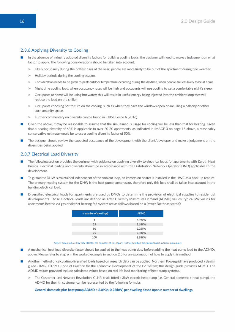
■ Diversified electrical loads for apartments are used by DNOs to determine the provision of electrical supplies to residential developments. These electrical loads are defined as After Diversity Maximum Demand (ADMD) values; typical kW values for apartments heated via gas or district heating fed system are as follows (based on a Power Factor as stated):
ADMD data produced by TUV SUD for the purposes of this report. Further detail on the calculations is available on request.
■ A mechanical heat load diversity factor should be applied to the heat pump duty before adding the heat pump load to the ADMDs above. Please refer to step 6 in the worked example in section 2.5 for an explanation of how to apply this method.
■ Another method of calculating diversified loads based on research data can be applied. Northern Powergrid have produced a design guide - IMP/001/911 Code of Practice for the Economic Development of the LV System; this design guide provides ADMD. The ADMD values provided include calculated values based on real life load monitoring of heat pump systems.
➤ The Customer-Led Network Revolution ‘CLNR’ trials fitted a 3kW electric heat pump (i.e. General domestic + heat pump), the ADMD for the nth customer can be represented by the following formula:
GeneraldomesticplusheatpumpADMD=6.093n-0.25(kW)perdwellingbaseduponnnumberofdwellings.
n(numberofdwellings) ADMD 1 6 .09kW 25 2 .68kW 50 2 .25kW 75 2 .03kW 100 1 .88kW
16 2.0 Design Guide

■ Tabulated values based on this formula are:
ADMD data produced by TUV SUD for the purposes of this report. Further detail on the calculations is available on request.
2.4 Sizing a Zeroth Heat Pump Distribution System
■ This section provides the designer with an overview of the procedures for determining the flowrates and sizing the pipework in a Zeroth Energy System and determining the flowrates required for pump selections.
■ Firstly, the Zeroth Heat Pumps will need to be selected for each apartment based on the guidance set out in section 2.2.
■ The primary flowrate for the development is calculated as follows:
➤ Using the diversity graphs and formulas outlined in section 2.3, calculate the total peak load for the development. This should include for any other systems connecting into the ambient loop, such as from landlord’s areas or commercial spaces.
➤ If the Zeroth Energy System is providing cooling, then calculate the peak total peak cooling load demand for the development, including any non-residential loads.
➤ Calculate the energy required from the Ambient Loop (total loop load).
➤ Add any allowance for system heat loss or gain, albeit this will be significantly less than that for a traditional heating or cooling system.
➤ The design flowrate will be based on the greater of the total loop load for heating or cooling demand.
➤ Design flowrate is:
Massflowrate(kg/s)=totalloopload(kW)÷(ΔTxCp).
WhereΔT=temperaturedifferencebetweenflow&return(5KfortheZerothEnergySystem).
Cp=SpecificHeatCapacityofwater(4.18kJ/(kg*K)at25°C).
➤ Note that the mass flowrate is approximately equal to the volumetric flowrate at 25°C:
Massflowrate(kg/s)≈volumetricflowrateat25°C.■ The flowrates across the whole network should be calculated, including branches and sub-branches, using the diversity guidance in
section 2.3.
■ For developments with cooling, the heating and cooling loads may need to be calculated to determine the highest flowrate on each particular section of the ambient loop.
■ Pipe sizing:
➤ Reference should be made to CIBSE Guide C for guidance velocity and pressure drop limits.
➤ Economic optimisation and lifecycle impacts may be considered, in order to find a compromise between annual heat loss, pump energy and capital cost. As heat loss from ambient loops are low compared to LTHW circuits, annual heat loss from pipework will be less of a driving factor in pipe sizing than electrical energy used for pumping.
➤ Higher pressure drops can be applied away from the index run as this will result in smaller pipework without additional pumping energy.
■ The flowrates on the index run will be used for sizing the ambient loop circulation pumps. Pumps should be selected based on software or spreadsheet calculation, based on the following principles:
➤ The following steps are to be used for the calculation:
■ Produce a schematic drawing of the pipe distribution.
NumberofBedrooms ADMD(0.95PF) 1Bed/Studio 1.2kW 2 Bed 1 .2kW 3 Bed 1 .5kW 4 Bed 1 .8kW
17 2.0 Design Guide

■ Determine the index run, usually this will be the terminal device furthest from the pumps, however if it is not clear then a number of options should be checked. This can be automated if using appropriate software.
➤ The pumps will normally be controlled to achieve a minimum pressure at a Differential Pressure Sensor (DPS) located on each riser or farthest branch.
➤ The DPS setpoint will be pressure required to satisfy the flowrate to the furthest Zeroth Heat Pump whilst achieving sufficient valve authority at the control valve serving this unit.
➤ Further explanation of pump speed control and DPS setpoints can be found in BG 12/2011 Energy Efficient Pumping Systems – A Design Guide (2012).
■ Determine the flowrates and pipe size on the index run using the pressure drop and velocity limits as described above. If using software this will be automated based on the criteria entered by the user. Tables in CIBSE Guide C4 can be used to select the correct pipe sizes.
■ Pressure drop coefficients (ζ or zeta) for all bends, branches and components should be determined.
■ Calculate the total pressure drop for the index run/s. This should include the required pressure through the index Zeroth Heat Pump.
■ Margins for flowrate and pressure drop are to be added as required. Care should be taken not to use excessive margins as this can result in oversized pumps which will run less efficiently. Refer to CIBSE Guide A (2016) and Guide B1 (2016) for further guidance.
➤ Achieve minimum required flowrate. The use of a jockey pump can be used to ensure that the minimum design flowrate can be achieved, and to provide efficient pumping at low loads. Jockey pumps can be sized by using a reduced flowrate in the index run pressure drop calculation.
2.4.1 Insulation Sizing
■ The specification of insulation for heating or cooling pipework is typically driven by the need to minimise heat losses (or gains) from the distribution system.
■ Since the central loop operates at near ambient temperatures, losses from the system are significantly less than that of traditional systems, with peak losses up to 90% less when compared to a standard heat network.
■ Ambient loop pipework should be provided with insulation in order to prevent condensation, similar to the requirements for cold water services and in accordance with BS 5422:2009.
2.5 Worked Example
■ This section provides a worked example of how a Zeroth Energy System might be sized.
■ A new development called Park Road consists of the following:
➤ 200 Apartments ➤ 75no. 1 bedroom, 1 bathroom apartments with a design occupancy of 2 ➤ 85no. 2 bedroom, 1 bathroom apartments with a design occupancy of 3 ➤ 40no. 3 bedroom, 2 bathroom apartments with a design occupancy of 4 ➤ All apartments are to be fitted with Zeroth Heat Pumps, heating only units
Step 1: Determine loads for each apartment type.
■ Calculate the heating load for each apartment type using an appropriate method, as outlined in section 2.2.2
■ The steady state heat load for each apartment type at Park Road is calculated as:
➤ 1 bedroom apartments: 1.1kW ➤ 2 bedroom apartments: 1.4kW ➤ 3 bedroom apartments: 1.8kW
■ Calculate the DHW usage using suitable demand profiles, refer to Appendices 1 and 2 for details.
18 2.0 Design Guide

Step 2: Select Zeroth Heat Pumps for each apartment type.
■ Based on consideration of the DHW profile plus space heating load for each apartment type, the following Zeroth Heat Pumps are selected:
➤ 1 bed apartments: 4kW unit ➤ 2 bed apartments: 4kW unit ➤ 3 bed apartments: 6kW unit
■ The following simplified nominal heat outputs are used as a basis for these selections:
➤ 4kW unit: Output 4.6kW at 55°C flow ➤ 6kW unit Output 6.0kW at 55°C flow
Step3:Determinediversityfactorsbasedonsections2.3.3and2.3.4.
■ Use the HWC diversity curve to determine the hot water diversity factor.
➤ For 200 apartments this is 12.8%
■ Use the Heating diversity curve to determine the heating diversity factor.
➤ For 200 apartments this is 62.2%
Step4:Determinethetotalpeakload.
■ Add up the total combined Zeroth Heat Pump hot water duties then multiply this by the hot water diversity factor.
➤ 1 bed apartments: 75 x 4.6kW = 345kW ➤ 2 bed apartments: 85 x 4.6kW = 391kW ➤ 3 bed apartments: 40 x 6.0kW = 240kW ➤ Total undiversified hot water load = 976kW ➤ Diversified load = 976kW x 12.8% = 125kW
■ Add up the total heating loads then multiply this by the heating diversity factor.
➤ 1 bed apartments: 75 x 1.1kW = 83kW ➤ 2 bed apartments: 85 x 1.4kW =119kW ➤ 3 bed apartments: 40 x 1.8kW = 72kW ➤ Total undiversified heating load = 274kW ➤ Diversified load = 274kW x 62.2% = 170kW
■ Add the diversified hot water and heating loads to obtain the total peak heat load:
➤ 125kW + 170kW = 295kW
■ In order to determine plant and distribution loads the Total Loop Load is then calculated. This is based on the required energy extraction from the loop as follows:
➤ The 4kW unit requires 3.6kW from the loop ➤ The 6kW unit requires 5.6kW from the loop
■ To calculate the Total Loop Load, adjust peak heat loads for each model of Zeroth Heat Pump:
TotalLoopLoad=Σ(Hotwaterloadxhotwaterdiversity+heatingloadxheatingdiversity)xloopheatextraction÷ZerothHeatPumpduty.
➤ 1 bed apartments: Loop load is (345kW x 12.8% + 83kW x 62.2%) x 3.6kW ÷ 4.6kW = 75kW ➤ 2 bed apartments: Loop load is (391kW x 12.8% + 119kW x 62.2%) x 3.6kW ÷ 4.6kW = 97kW ➤ 3 bed apartments: Loop load is (345kW x 12.8% + 83kW x 62.2%) x 5.6kW ÷ 6.0kW = 70kW ➤ Total Loop Load is 75kW + 97kW + 70kW = 242kW
19 2.0 Design Guide

Step5:Sizethedistributionsystemasdescribedintheprevioussection.■ The design primary flowrate for Park Road is: ➤ Flowrate (kg/s) = Total loop load (kW) ÷ (∆T x Cp) ➤ 242kW ÷ (5K x 4.18 kJ/(kg*K) = 11.59kg/s
■ The pipework can then be sized using CIBSE tables. Assuming the criteria: ➤ Heavy grade steel pipe ➤ Pressure drop limit of 200Pa/m ➤ Velocity limit between 1.25m/s & 3m/s (for sizes over 50mmø)
■ The resulting pipe size for the Total Loop Load is: ➤ Nominal 100mmø pipe ➤ 197Pa/m pressure drop ➤ 1.4m/s velocity
■ The same procedure is then used to determine flowrates and pipe sizing across the whole system.
■ When sizing pumps and plant the designer should consider whether it is appropriate to add a margin. The use of design margins is outside the scope of this document; however, reference can be made to CIBSE Guide A (2016) and Guide B1 (2016).
Step 6: Determine the combined Zeroth Heat Pump electrical loads for the development:■ An overall heat load diversity figure is generated as follows: ➤ Total peak heat load = 295kW ➤ Connected load = sum of Zeroth Heat Pump duties = 976kW ➤ Overall heat load diversity = 295kW ÷ 976kW = 30.2%
■ Using this mechanical heat load diversity factor of 30.2% applying this diversity factor to the Zeroth Heat Pump maximum electrical demand results in the following:
➤ The 4kW unit diversified load: 1.06kW x 30.2% = 0.32kW ➤ The 6kW unit diversified load: 1.46kW x 30.2% = 0.44kW
■ Below is a table using the DNO’s ADMD + Zeroth Heat Pump load for an apartment based on the number of bedrooms.
ADMD data produced by TUV SUD for the purposes of this report. Further detail on the calculations is available on request.
■ Based on the DNO’s ADMD and the heat pump electrical diversity load factor of 30.2%, an average apartment would require 1.60kW to suit the demand.
■ As an alternative method of calculation, the designer could use Northern Powergrid’s design guide - IMP/001/911 Code of Practice for the Economic Development of the LV System.
■ Using the formula - ADMD = 6.093n-0.25 (kW) per dwelling based upon n number of dwellings.
ADMD data produced by TUV SUD for the purposes of this report. Further detail on the calculations is available on request.
■ Comparing the CLNR trial ADMD against typical DNO ADMD values the electrical demand progressively reduces as the number of apartments increases.
NumberofBedrooms NumberofApartments ADMD(0.95PF) ZerothHeatPumpLoad Diversifiedelectricalloadperapartment
80 80 0 8 .72 9 .88 1 Bed 75 1 .2kW 0 .32kW 1 .52kW 2 Bed 85 1 .2kW 0 .32kW 1 .52kW 3 Bed 40 1 .5kW 0 .44kW 1 .94kW Average ADMD 1 .60kW
n(numberofdwellings) ADMD 100 1 .88kW 125 1 .80kW 150 1 .70kW 175 1 .70kW 200 1 .60kW
20 2.0 Design Guide

Glen Dimplex Heating & Ventilation (GDHV) has pioneered the Zeroth Energy System principal, leading the way in offering solutions for changing compliance and proving them with successfully completed installations designed for modern construction and living.
As a specialist HVAC solution provider, GDHV are able to offer design guidance advice for projects looking to specify the Zeroth Energy System. This includes being able to offer advice and solutions for the central plant and emitter options, including commercial ASHP, low temperature fan assisted radiators and fan coil units, to complete the Zeroth system offering.
To discuss the Zeroth Energy System or this guide in more detail, including case studies or to request GDHV’s CIBSE accredited Zeroth CPD, email [email protected]
21 2.0 Design Guide

3.0 Glossary of Terms and Acronyms■ Ambient Loop (also Energy Loop or Neutral Loop) Flow and return pipes conveying near-ambient temperature
water from a heat or coolth source to water source heat pumps. The water source heat pumps extract energy from the water to provide the required application such as heat-ing, cooling, DHW, or refrigeration.
■ Ameliorate To make better or more tolerable. Ameliorated cooling is the
provision of cooling to enhance thermal comfort but not provide the full cooling output of a traditional system, ie achieving 25-26°C rather than 21-22°C.
■ BMS Building Management System - a computer-based control
system installed in buildings that controls and monitors the building's mechanical and electrical equipment such as heating, cooling, ventilation, lighting, power systems.
■ Connected load Sum of the energy rating of all devices connected to a
distribution system.
■ Coolth The noun form of “cool”; opposite of heat.
■ Designer The lead person carrying out the design.
■ DHW Domestic Hot Water.
■ DistrictHeating The provision of heat to a group of buildings, district or
whole city usually in the form of piped hot water from one or more centralised heat sources.
■ Diversity Peak load that occurs at a point in a distribution system
divided by the connected load at the same point in the system. Also, refer to the definition as applied to heat networks in section 2.2.3.
■ DNO Distribution Network Operator, a company licensed to
distribute electricity in the UK.
■ Heat Network The flow and return pipes that convey the heat from the
energy centre to the customers. The pipes are often buried but may be above ground or within buildings.
■ HIU Heat Interface Unit - consists of a pre-fabricated
assembly of components that form the interface between the heat network and the dwelling’s heating system.
■ HWC Hot Water Cylinder. In the context of this paper, this is often
referring to the cylinder integral to the Zeroth Heat Pump.
■ HWC reheat mode Zeroth Heat Pump Hot Water Cylinder reheat mode. This is
the DHW production mode; when enabled the heat pump will operate at 100% to heat up the contents of the HWC to the setpoint temperature.
■ Index run The pipe run with the maximum pressure drop. Typically,
this will be from the pumps up to and including the farthest device, such as a heat emitter, HIU or Zeroth Heat Pump.
■ LTHW Low Temperature Hot Water - Hot water at up to 95ºC used
for space heating and low temperature process.
■ Plantsizeratio Installed heat emission divided by the design heat load.
■ Steady state heat load The heat load of the space/building/dwelling under constant
design winter conditions.
■ Zeroth Energy System System typically consisting of Zeroth Heat Pumps, ambient
loop and central plant such as heat/coolth generating equipment, pumps, heat exchangers etc.
■ Zeroth Heat Pump Water to water heat pump manufactured by Glen Dimplex
Heating & Ventilation. Located in apartments or commercial spaces, it extracts energy from an ambient loop to provide space heating/cooling and DHW from an integral HWC.
22 3.0 Glossary of terms and Acronyms

4.0 ReferencesBG 12/2011 Energy Efficient Pumping Systems – A Design Guide, BSRIA 2012.
BS 5422 (2009) Method for specifying thermal insulating materials for pipes, tanks, vessels, ductwork and equipment operating within the temperature range –40 °C to +700 °C.
BS EN 50440 (2015) Efficiency of domestic electrical storage water heaters and testing methods (+A1:2020).
BS EN 16147 (2017) Heat pumps with electrically driven compressors. Testing, performance rating and requirements for marking of domestic hot water units.
CIBSE (2016) Guide A: Environmental Design (London: Chartered Institution of Building Services Engineers).
CIBSE (2016) Guide B1: Heating (London: Chartered Institution of Building Services Engineers).
CIBSE (2007) Guide C4: Flow of Fluids in Pipes and Ducts (London: Chartered Institution of Building Services Engineers).
CIBSE Guide CP1: (2020) Heat Networks: Code of Practice for the UK (London: Chartered Institution of Building Services Engineers).
CIBSE (2006) How to design a heating system: CIBSE Knowledge Series: KS8 (London: Chartered Institution of Building Services Engineers).
CIBSE (2006) Variable flow pipework systems CIBSE Knowledge Series KS7 (London: Chartered Institution of Building Services Engineers).
CIBSE (2009) Variable flow pipework systems: valve solutions: Supplement to CIBSE Knowledge Series KS7 (London: Chartered Institution of Building Services Engineers).
Dansk Standard (2009) DS 439: Code of Practice for domestic water supply installations (Charlottenlund, Denmark: Dansk Standard).
Energy Saving Trust paper: Measurement of Domestic Hot Water Consumption in Dwellings (2008).
HWA/CP1: (2018) Design Guide for Stored Hot Water Solutions in Heat Networks, Northern Powergrid.
IMP/001/911 Code of Practice for the Economic Development of the LV System V5.0/Northern Power Grid/2018.
ISO 12241 (2008) Thermal insulation for building equipment and industrial installations - Calculation rules.
Metering Requirements - Zeroth, Zeroth Energy System (ZCD27 REV A 27/07/2018), Glen Dimplex Heating & Ventilation.
NHBC Standards (2020).
Official Journal of the European Union (2013) Commission Regulation (EU) No 813/2013. Implementing Directive 2009/125/EC of the European Parliament and of the Council with regard to ecodesign requirements for space heaters and combinations heaters.
Swedish District Heating Association (2016) Technical Regulations F:101: District heating substations - design and installation (Stockholm: Energi Foretagen/Swedish District Heating Association).
Varme Ståbi (7th edition, 1st print 2015) published by Praxis – Nyt Teknisk Forlag.
Zeroth Apartment Heat Pump with integrated cylinder (ZCD1_Is-sue 1 06/09/2019), Glen Dimplex Heating & Ventilation.
Zeroth - Understanding the benefits of a low temperature energy system (ZCD24 RevA), Glen Dimplex Heating & Ventilation.
Image 9 - Typical Ambient Loop Apartment Connection Detail, 2017.
Image 10 - Typical Ambient Loop Branch Detail Using PICVs, 2017.
Image 11 - Typical Ambient Loop Connection to Plate Heat Exchanger, 2017.
Image 12 - Typical Ambient Loop Connection to Plate Heat Exchanger, 2017.
Drawing 1 – Example Mixed Technology System Schematic, 2017.
23 4.0 References

Appendices
24 Appendix 1
ERP Profiles
■ The Zeroth Heat Pumps have been tested in accordance with ErP Directive 2009/125/EC and BS EN 50440 (2015). This test involves applying load profiles to the unit to determine the hot water capability of the unit against benchmark ratings. The load profiles consist of a sequence of hot water draw-offs to a fixed schedule that represent a daily usage pattern. The following images summarise the profiles and draw-offs that are required to be achieved for different ratings. Each of the Zeroth Heat Pump models achieves an XXL rating.
■ The designer can use these profiles understanding the DHW capability of the Zeroth Heat Pump and setting or comparing against a target performance or criterion.
■ These profiles are based on hot water provision; the capacity of the Zeroth Heat Pump may differ where there is a demand for space heating or cooling.
Appendix 1
Small sink0.105 kWh3L(V40 volume)
Large shower1.82 kWh40.5L(V40 volume)
Large sink0.315 kWh9.1L(V40 volume)
Small bath3.605 kWh52.6L(V40 volume)
Small shower1.4 kWh40.5L(V40 volume)
Large bath4.42 kWh127L(V40 volume)
Image 4: Assigned Energy and Hot Water Use at a mixed outlet temperature
of 40°C for different end uses from BS EN 16147: 2017
Image 5: Assigned Energy and Hot Water Use at a mixed outlet temperature of 40°C for different end uses from BS EN 16147: 2017
M
5.84
Time Draw-offs
6x 1x
3x 1x
5x 1x1x
5x
Energy (kWh) Volume (L) at 40ᵒ
2.135 61.31
0.525 15.08
0.63 18.09
2.55 73.22
07:00 - 09:00
09:01 - 12:00
12:01 - 17:00
17:01 - 22:00
Total 167.70

Image 5: Assigned Energy and Hot Water Use at a mixed outlet temperature of 40°C for different end uses from BS EN 16147: 2017
Image 5: Assigned Energy and Hot Water Use at a mixed outlet temperature of 40°C for different end uses from BS EN 16147: 2017
Image 5: Assigned Energy and Hot Water Use at a mixed outlet temperature of 40°C for different end uses from BS EN 16147: 2017
L
11.655
Time Draw-offs
6x1x1x
3x 1x
5x
Energy (kWh) Volume (L) at 40ᵒ
5.635 161.81
0.525 15.08
0.63 18.09
4.865 139.70
07:00 - 09:00
09:01 - 12:00
12:01 - 17:00
17:01 - 22:00
Total 334.67
5x 1x 1x
XL
19.07
Time Draw-offs
7x
Energy (kWh) Volume (L) at 40ᵒ
6.87 197.27
0.735 21.11
1.26 36.18
10.205 293.04
07:00 - 09:00
09:01 - 12:00
12:01 - 17:00
17:01 - 22:00
Total 547.60
6x
5x1x
1x
2x6x 1x
1x
XXL
24.53
Time Draw-offs
7x
Energy (kWh) Volume (L) at 40ᵒ
8.69 249.53
0.735 21.11
1.26 36.18
13.845 397.56
07:00 - 09:00
09:01 - 12:00
12:01 - 17:00
17:01 - 22:00
Total 704.38
6x
5x2x
1x
2x6x 1x
2x
2x
25 Appendix 1
Further information is available via the Commission Regulation (EU) No. 813/2013. https://eur-lex.europa.eu/legal-content/EN/TXT/PDF/?uri=CELEX:32013R0813&from=EN

Comparison of HWCs & HIUs - Decoupling Demand
■ This section explains the pros and cons of HWCs & HIUs for the generation of domestic hot water in dwellings.
■ There are a number of benefits of using stored hot water over instantaneous hot water generation. One of these is that the whole system, including all HWCs, acts as a thermal battery which can be charged during off peak periods, ready to be discharged during peak periods such as the ‘morning rush’. For example, a block of 100 apartments, each with a fully charged 180 litre HWC at, say, 5am, is equal to a total of 1 MWh of stored energy.
■ The same amount of energy stored centrally would require 180,000 litres of thermal storage vessel capacity (at equivalent temperatures).
■ With locally stored thermal energy, there is an opportunity to decouple the peak hot water demand from the load on the central plant. This will have the benefit of reducing the size of the central plant.
■ It will smooth peaks and increase run time for central plant, thus benefiting equipment that favours long run times without stop / starts such as heat pumps and CHP.
Appendix 2
■ The peak demand per apartment differs significantly between instantaneous and stored water solutions. For instantaneous hot water generation such as HIUs this will typically be 35kW to 50kW per dwelling. For a stored water solution such as the Zeroth Heat Pump, the peak demand will be 4.6kW or 6.0kW, depending on the model (actual heat from the loop will be less than this due to contribution from the Zeroth Heat Pump condenser).
26 Appendix 2
Reduced size of central plant
Decentralisedthermalstorage,whichisusedtobufferagainstpeaks and troughs in total demand
Electrical immersion heater as backup means occupants have access to hot waterduringshort-terminterruptionstotheheatnetwork,suchasduetofailure or planned maintenance
No requirement to maintain temperatures in network during quiet periods
Significantlyreducedheatlossfromnetwork
Reducedriskofoverheatingincommonareaswherepipeworkpassesthrough
Canmakeuseofintermittentheatsources
Opportunitytoscheduletimeswhenheatisdrawnfromthenetwork
BenefitsofHWCsaspartoftheZerothEnergySystem BenefitsofHIUs
Less space required in dwelling for equipment
Nolimittodurationofhotwaterdraw-off
No requirement to store water at 60°C for legionella control
Lessheatlossthanfromacylinder,althoughduringtheheatingseasonthiswillbeusefulheat(incontrasttoheatlossfromthenetwork)

27 Appendix 3
Zeroth Pipework Systems
■ Features of ambient loops:
➤ Can supply heating and cooling loads simultaneously.
➤ Energy can be extracted or injected into the loop at various points.
➤ Central plant interfaces with the ambient loop either directly or indirectly via plate heat exchangers.
➤ The ambient loop should be designed as a variable flow system, consisting of appropriate valve selections and a pump set designed to operate efficiently over the required range of flowrates.
➤ It is recommended to use Pressure Independent Control Valves (PICVs) at the connection to each Zeroth Heat Pump. This will ensure that constant flow will be available to the unit across differing pressures in the local branch. An example hydraulic connection to a Zeroth Heat Pump is indicated below.
Key for image 9:
Appendix 3
US (User Side)EL (Energy Loop)
US.06US.07EL.04
US.05
US.04
US.03
EL.03
EL.02
EL.05
EL.06
EL.07EL.01
EL.08 EL.08
EL.08
US.02
US.01
US.08
US.09
US.10
US.11
US.14US.14
US.12
F P
TS
TS
TS
F
Image 9 - Typical Ambient Loop Apartment Connection Detail, FROM YEAR
EL EL 01 EL 02 EL 03 EL 04 EL 05 EL 06 EL 07 EL 08
Filter Drain valve Flexible hose HeatexchangerEL Temperature sensor EL Flow sensor EL PICvalve Isolationvalve
US US 01 US 02 US 03 US 04 US 05 US 06 US 07 US 08 US 09 US 10 US 11 US 12 US 13 US 14
Filter 8L Expansion vessel Drain valve Flexible hose Pump Temperature sensor US HeatexchangerUS Fill valve US PressureGaugeUS Temperature sensor US Flow sensor US SafetyValve Air vent Isolationvalve
Key for images 9-11:
IV IsolationValve PIVC PressureIndependentControlValve NC Normally Closed TP TestPoint STR Strainer ZHP ZerothHeatPump DifferentialPressureSensor PressureGauge T Temperature Sensor OP OrificePlate AAV AutomaticPressureSensor FC Flexible Coupling DC Drain Cock NRV Non-ReturnValve 3PMV 3-PortMotorisedValve
➤ For guidance on how to design a system incorporating PICVs refer to Variable Flow Pipework Systems: Valve Solutions: Supplement to CIBSE Knowledge Series KS7 (2009).
➤ An example branch schematic is provided below.

ZHP
STR
TPTP
IV
IV
IV IV
IV
IV
IV (N/C)
IV
OP
OP
IV
IV IV
PICV IV
IV IV
PICV IV
IV IV
PICV IV
IV IV
PICV IV
IV IV
PICV
IV
IV IV
PICV IV
IV IV
PICV IV
IV IV
PICV IV
IV IV
PICV IV
IV IV
PICV
IV
IV IV
PICV IV
IV IV
PICV IV
IV IV
PICV IV
IV IV
PICV IV
IV IV
PICV
ZHP
STR
TPTP
ZHP
STR
TPTP
ZHP
STR
TPTP
ZHP
STR
TPTP
ZHP
STR
TPTP
ZHP
STR
TPTP
ZHP
STR
TPTP
ZHP
STR
TPTP
ZHP
STR
TPTP
ZHP
STR
TPTP
ZHP
STR
TPTP
ZHP
STR
TPTP
ZHP
STR
TPTP
TP
IV
TP
ZHP
STR
TPTP
REVERSE ACTING DIFFERENTIALPRESSURE VALVE
STR
IV
CONNECTION TOHEAT SOURCE
LOOP CIRCULATION PUMPS
DC DC
AAV
TP TPFC
P PFCIV IVNRV
TP TPFC
P PFCIV IV
IV IV
NRV
Image 10 - Typical Ambient Loop Branch Detail Using PICVs, FROM YEAR
28 Appendix 3

29 Appendix 3
■ Image 10 consists of the following features:
➤ Reverse acting differential pressure valve at the top of the riser. This will be set to open if all other valves on the system shut due to no load. The function of this is to prevent the pumps operating against a closed head.
➤ Pump speed control. Differential pressure sensors should be provided close to the most remote branch on each riser. Pump speed should be controlled to maintain a minimum differential pressure setpoint at each sensor. The minimum pressure setting should be sufficient to achieve the required flowrate at the farthest (index) heat pump.
➤ The use of PICVs will mean that the system is inherently self-balancing. Typically, this will mean that, depending on the size of the system, additional regulating valves or commissioning sets may not be required. Riser provision could consist of isolation valves and a flow measurement device to be used during commissioning.
➤ Note that project specific provision for flushing and drain down should be included as required.
■ Heat source connection options.
➤ There are a number of ways the ambient loop can be interfaced with the primary systems supplying heat (or coolth):
➤ Plate heat exchanger ➤ Low loss header ➤ Buffer vessel ➤ Direct connection (applicable to small systems)
■ Image 11 shows a simplified detail for a plate heat exchanger interface to an ambient loop.
➤ Plate heat exchangers may be required to separate the primary and secondary circuits in the following situations:
➤ When glycol is required in the primary circuit ➤ When the primary circuit is operated by a third party, such as for a typical district heating network ➤ To manage temperature differentials between the primary and secondary circuits ➤ To maintain the primary circuit in case of failure of the secondary circuit and vice versa
Image 11 - Typical Ambient Loop Connection to Plate Heat Exchanger, FROM YEAR
➤ Image 11 includes the provision of a 3-port mixing valve on the secondary circuit. The 3-port mixing valve is controlled to deliver 25°C into the ambient loop. Note that a 3-port valve may not necessarily be required if the flow through the primary circuit can be controlled to achieve the delivery temperature. The designer should make a decision based on the parameters specific to the system. Response time for 3-port valves opening and closing should also be considered.
➤ A 2-port valve may be required to isolate flow to the heat exchanger, such as when multiple heat exchangers are connected into the system and the total duty is being provided by one heat exchanger at a time.
➤ The PICV on the primary circuit is controlled to match the temperature required on the secondary circuit. In large systems, rather than being a single valve, the PICV setup will typically consist of a 2-port motorised valve and Differential Pressure Control Valve (DPCV). An explanation of these valves can be found in BG 12/2011 Energy Efficient Pumping Systems – A Design Guide (2012).
T
3PMVIV
IV
IVPICV
PLATE HEATEXCHANGER
PRIMARY CIRCUIT SECONDARY CIRCUIT
IV

■ Image 12 shows a simplified detail for a low loss header interface to an ambient loop.
➤ Low loss headers are used to separate the primary and secondary circuits in the following situations:
➤ When flowrates differ between the primary and secondary circuits. The flowrate on the secondary circuit will be controlled to match the demand on the network whereas the primary circuit flowrate may be controlled to the loading and unloading of the primary heat generator.
➤ To act as a buffer between the circuits.
➤ To act as a manifold when there are multiple secondary circuits.
Image 12 - Typical Ambient Loop Connection to Plate Heat Exchanger, FROM YEAR
➤ Image 12 includes the provision of a 3-port mixing valve on the secondary circuit. The 3-port mixing valve is controlled to deliver 25°C into the ambient loop. This is required when the heat source exceeds 25°C for heating or is less than 25°C for cooling.
T
3PMVIV
IV
LOW LOSSHEADER
PRIMARY CIRCUIT SECONDARY CIRCUIT
IV
IV
30 Appendix 3

Guidance on Buffer Vessels or Thermal Storage Vessels
■ Thermal storage vessels are typically used to maximize the use of renewable or low carbon energy sources such as heat pumps or CHP units. During periods of low demand, the vessels are topped up ready to serve periods of high demand.
■ The Zeroth Energy System by default has a significant amount of in-built thermal storage via the HWCs. This distributed storage is significant; for a block of 200 dwellings the combined HWC volume is 34,400 litres. With all cylinders topped up this would provide a simultaneous hot water capacity of 7.5MW.
■ This type of system effectively smooths out the peaks and troughs in demand throughout the day, thus levelling out the load.
■ Central thermal storage therefore has the potential to be minimised or omitted as a result of the distributed storage. Consideration should be given to the heat source in deciding on whether thermal storage is required. Intermittent technologies, such as solar thermal, will still require central thermal storage to optimise their operation.
■ Buffer vessels serve a different purpose and may still be required independently of distributed storage. They are typically used to prevent of cycling of heat pumps, chillers and CHP units by allowing for a minimum run time. They can also be used to reduce the peak boiler capacity by providing top-up heat during the peak load period.
■ Depending on where it is located in the primary circuit, a vessel can often act as both thermal storage and buffer; the main difference being the volume and mode of operation. Buffers specified for run time should be sized to achieve a maximum number of stop/starts per hour and will typically be smaller than thermal stores.
Appendix 4
Metering Requirements
■ The following section is taken from the Glen Dimplex Heating & Ventilation document Metering Requirements – Zeroth (2018).
■ The Zeroth Energy System differs from traditional heat network designs because it falls outside of the scope of the Heat Network (Metering and Billing) Regulations 2014. This section outlines the possible metering and billing arrangements that could be adopted by a developer when adopting this type of system.
Why is Zeroth out of scope?
■ Glen Dimplex Heating & Ventilation (GDHV) have undertaken substantial consultation with the Department for Business, Energy and Industrial Strategy (BEIS) to determine if the Zeroth Energy System could be considered in or out of scope from the Heat Network (Metering and Billing) Regulations 2014. After this period of consultation BEIS agreed that the Zeroth Energy System can be considered outside of the scope of the regulation. The impact of this decision is that there is no official metering or monitoring requirement of the system for billing purposes.
■ Further information on metering requirements for the Zeroth Energy System is available from Glen Dimplex Heating & Ventilation.
Appendix 5
31 Appendix 4/5

32 Appendix 6/7
Appendix 6
PLANTBUFFER
PLATE HEAT EXCHANGER
ZEROTH HEAT PUMPS
BUFFER
PLANT
PLATE HEAT EXCHANGER
ZEROTH HEAT PUMPS
BUFFER
PLANT
Heating and cooling
Parallel buffer vessel required for reducing peak demands and to overcome system lags, between compressor starts. Size store based on peak load analysis.
Appendix 7
Heating
Non Return Valve arrangement permits draw down of the buffer tank without heat source operation and reduces pump duties.
PLANTBUFFER
PLATE HEAT EXCHANGER
ZEROTH HEAT PUMPS
BUFFER
PLANT
PLATE HEAT EXCHANGER
ZEROTH HEAT PUMPS
BUFFER
PLANT
