design guide - sub-zero, wolf, and cove appliances
TRANSCRIPT
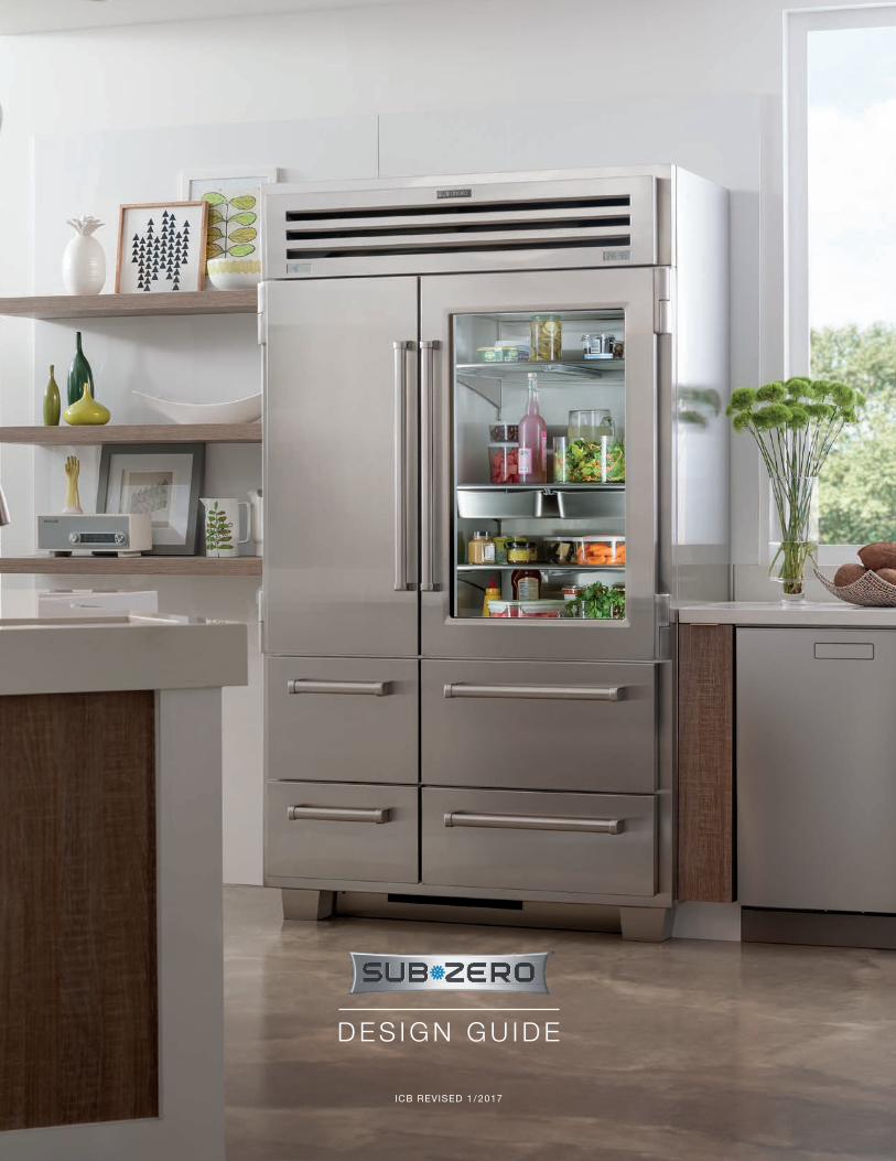
ICB REVISED 1 / 2017
D E S I G N G U I D E

TA B L E O F C O N T E N T S
3 B U I LT- I N R E F R I G E R AT I O N
30 P R O 4 8 R E F R I G E R AT I O N
35 I N T E G R AT E D R E F R I G E R AT I O N
44 W I N E S T O R A G E
72 S U B - Z E R O W A R R A N T I E S
Features and specifications are subject to change at any time without notice.
Throughout this guide, dimensions may vary by ± 3 mm.

subzero.com | 3
BUILT-IN REFRIGERATION
Built-In Refrigeration
Sub-Zero designers and engineers continue to perfect the built-in line. The addition of LED lighting throughout and several new models with internal water dispensers, along with the same advanced food preservation technology Sub-Zero is known for, make the built-in line nothing short of revolutionary.
BUILT-IN MODELS
ICBBI-36R
ICBBI-36F
ICBBI-36UID
ICBBI-36UFDID
ICBBI-36S
ICBBI-42S
ICBBI-42SD
ICBBI-48S
ICBBI-48SID
ICBBI-48SD
BU
ILT
-IN
PR
O 4
8IN
TE
GR
AT
ED
WIN
E
ICBBI-42UFDID
4 | English
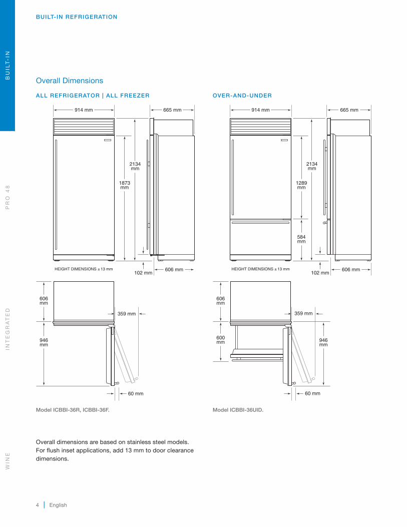
Overall Dimensions
ALL REFRIGERATOR | ALL FREEZER
Overall dimensions are based on stainless steel models. For flush inset applications, add 13 mm to door clearance dimensions.
Model ICBBI-36R, ICBBI-36F.
BUILT-IN REFRIGERATION
914 mm
2134mm
102 mm
1873mm
606mm
946mm
359 mm
606 mm
60 mm
HEIGHT DIMENSIONS ± 13 mm
665 mm
OVER-AND-UNDER
Model ICBBI-36UID.
914 mm
2134mm
102 mm
1289mm
584mm
606mm
600mm 946
mm
606 mm
60 mm
HEIGHT DIMENSIONS ± 13 mm
665 mm
359 mm
WIN
EIN
TE
GR
AT
ED
PR
O 4
8B
UIL
T-
IN

subzero.com | 5
BUILT-IN REFRIGERATION
Model ICBBI-36UFDID.
914 mm
2134mm
102 mm
1289mm
584mm
606mm
600mm
495mm
203mm
606 mmHEIGHT DIMENSIONS ± 13 mm
60 mm
665 mm
BU
ILT
-IN
PR
O 4
8IN
TE
GR
AT
ED
WIN
E
Overall Dimensions
OVER-AND-UNDER
Model ICBBI-42UFDID.
1067 mm
2134mm
102 mm
1289mm
584mm
606mm
565mm
229mm
606 mmHEIGHT DIMENSIONS ± 13 mm
60 mm
665 mm
600mm

6 | English
BUILT-IN REFRIGERATION
Model ICBBI-36S.
914 mm
2134mm
102 mm
1873mm
606mm
565mm
184mm
222mm
606 mm
60 mm
HEIGHT DIMENSIONS ± 13 mm
665 mm
Overall Dimensions
SIDE-BY-SIDE
Model ICBBI-42S, ICBBI-42SD.
1067 mm
2134mm
102 mm
1873mm
606 mm
606mm
668mm
264mm
191mm
60 mm
HEIGHT DIMENSIONS ± 13 mm
665 mm
WIN
EIN
TE
GR
AT
ED
PR
O 4
8B
UIL
T-
IN

subzero.com | 7
BUILT-IN REFRIGERATION
Overall Dimensions
SIDE-BY-SIDE
Model ICBBI-48S, ICBBI-48SID, ICBBI-48SD.
1219 mm
2134mm
102 mm
1873mm
606 mm
606mm
762mm
295mm
213mm
60 mm
HEIGHT DIMENSIONS ± 13 mm
665 mm
Specifications
INTERIOR CAPACITY
ALL REFRIGERATOR | ALL FREEZER R (L) F (L)
ICBBI-36R 613ICBBI-36F 612
OVER-AND-UNDER R (L) F (L)
ICBBI-36UID 367 143ICBBI-36UFDID 357 144ICBBI-42UFDID 420 220
SIDE-BY-SIDE R (L) F (L)
ICBBI-36S 328 225ICBBI-42S 430 220ICBBI-42SD 408 194ICBBI-48S 500 264ICBBI-48SID 491 244ICBBI-48SD 478 244
BU
ILT
-IN
PR
O 4
8IN
TE
GR
AT
ED
WIN
E

8 | English
BUILT-IN REFRIGERATION
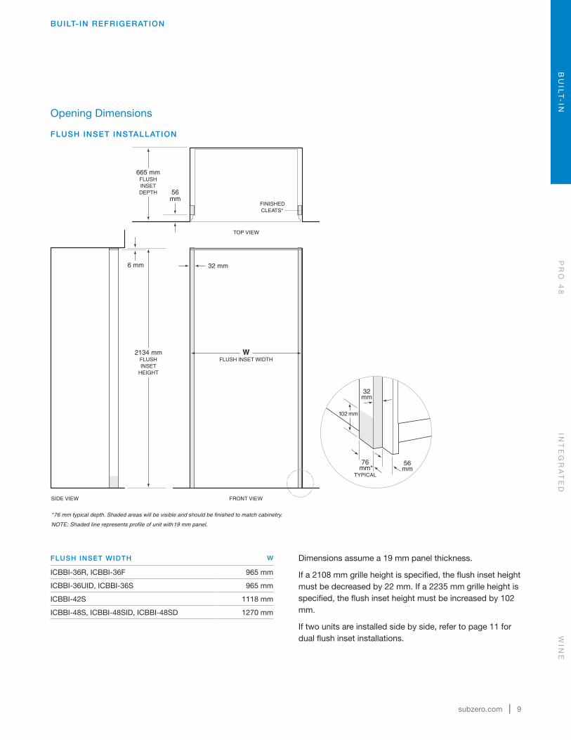
Opening Dimensions
STANDARD INSTALLATION
2127 mmOPENINGHEIGHT
610 mmOPENING
DEPTH
NOTE: Shaded line represents profile of unit.
FRONT VIEWSIDE VIEW
TOP VIEW
WOPENING WIDTH
OPENING WIDTH W
ICBBI-36R, ICBBI-36F 902 mm
ICBBI-36UID, ICBBI-36UFDID, ICBBI-36S 902 mm
ICBBI-42UFDID, ICBBI-42S, ICBBI-42SD 1054 mm
ICBBI-48S, ICBBI-48SID, ICBBI-48SD 1206 mm
If a 2108 mm grille height is specified, the opening height must be decreased by 22 mm. If a 2235 mm grille height is specified, the opening height must be increased by 102 mm.
If two units are installed side by side, refer to page 10 for dual standard installations.
WIN
EIN
TE
GR
AT
ED
PR
O 4
8B
UIL
T-
IN
subzero.com | 9
BUILT-IN REFRIGERATION
Opening Dimensions
FLUSH INSET INSTALLATION
FLUSH INSET WIDTH W
ICBBI-36R, ICBBI-36F 965 mm
ICBBI-36UID, ICBBI-36S 965 mm
ICBBI-42S 1118 mm
ICBBI-48S, ICBBI-48SID, ICBBI-48SD 1270 mm
Dimensions assume a 19 mm panel thickness.
If a 2108 mm grille height is specified, the flush inset height must be decreased by 22 mm. If a 2235 mm grille height is specified, the flush inset height must be increased by 102 mm.
If two units are installed side by side, refer to page 11 for dual flush inset installations.
2134 mmFLUSHINSET
HEIGHT
6 mm
665 mmFLUSHINSETDEPTH 56
mm
*76 mm typical depth. Shaded areas will be visible and should be finished to match cabinetry.
NOTE: Shaded line represents profile of unit with19 mm panel.
FRONT VIEWSIDE VIEW
TOP VIEW
FINISHEDCLEATS*
32 mm
WFLUSH INSET WIDTH
102 mm
32mm
56mm
76 mm*
TYPICAL
BU
ILT
-IN
PR
O 4
8IN
TE
GR
AT
ED
WIN
E
10 | English
BUILT-IN REFRIGERATION
Opening Dimensions
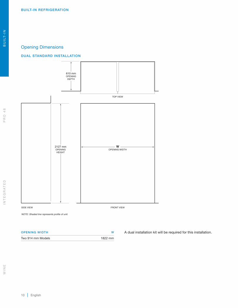
DUAL STANDARD INSTALLATION
2127 mmOPENINGHEIGHT
610 mmOPENING
DEPTH
NOTE: Shaded line represents profile of unit.
FRONT VIEWSIDE VIEW
TOP VIEW
WOPENING WIDTH
OPENING WIDTH W
Two 914 mm Models 1822 mm
A dual installation kit will be required for this installation.
WIN
EIN
TE
GR
AT
ED
PR
O 4
8B
UIL
T-
IN
subzero.com | 11
BUILT-IN REFRIGERATION
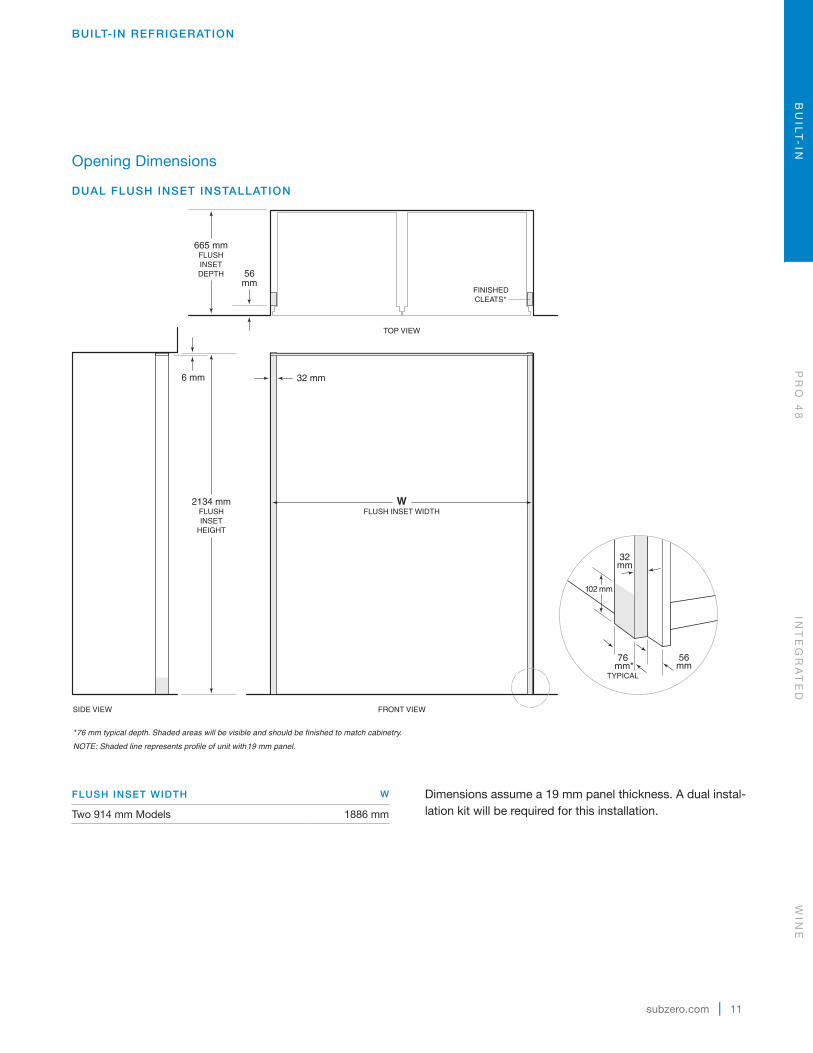
Opening Dimensions
DUAL FLUSH INSET INSTALLATION
2134 mmFLUSHINSET
HEIGHT
6 mm
665 mmFLUSHINSETDEPTH 56
mm
*76 mm typical depth. Shaded areas will be visible and should be finished to match cabinetry.
NOTE: Shaded line represents profile of unit with19 mm panel.
FRONT VIEWSIDE VIEW
TOP VIEW
FINISHEDCLEATS*
32 mm
WFLUSH INSET WIDTH
102 mm
32mm
56mm
76 mm*
TYPICAL
FLUSH INSET WIDTH W
Two 914 mm Models 1886 mm
Dimensions assume a 19 mm panel thickness. A dual instal-lation kit will be required for this installation.
BU
ILT
-IN
PR
O 4
8IN
TE
GR
AT
ED
WIN
E

12 | English
BUILT-IN REFRIGERATION
Plumbing
For built-in models with an automatic ice maker, the water supply line should be located within the shaded area shown in the illustration below. The water supply line should be connected to the house supply with an easily accessible shut-off valve. Do not use self-piercing valves. The water supply line must not interfere with installation of the anti-tip brackets.
A reverse osmosis system can be used provided there is constant water pressure of 2.4–8.3 bar supplied to the unit at all times. A copper line is not recommended for this application.
Installation must comply with all applicable plumbing codes.
PLUMBING REQUIREMENTS
Water Supply Line 6.35 mm OD copper line, braided stainless steel, or PEX tubing
Water Pressure 2.4–8.3 bar
Excess Water Line for Connection .9 m
Electrical
International models from the factory designed without a transformer require a 220-240 V AC, 50/60 Hz electrical supply, fused at the correct rating for the unit. If required by local or national codes, the power cord can be easily replaced using the power inlet device.
The electrical supply should be located within the shaded area shown in the illustration below. A separate circuit, ser-vicing only this appliance is required. A ground fault circuit interrupter (GFCI) is not recommended and may cause inter-ruption of operation.
Installation must comply with all applicable electrical codes.
ELECTRICAL REQUIREMENTS
Power Supply 220-240 V AC, 50/60 Hz
Circuit Breaker 10 amp
Receptacle grounding-type (earthed)
1918 mmFROM FLOOR
178mm E
152mm
RIGHT SIDEOF OPENING
Electrical supply location.
76 mm
457 mm152mm
RIGHT SIDEOF OPENING
AREA EXTENDS 13 mmFORWARD ON FLOOR
Water supply location.
WIN
EIN
TE
GR
AT
ED
PR
O 4
8B
UIL
T-
IN
subzero.com | 13
Custom Panels
For overlay and flush inset applications, custom door panels must be provided. Handle hardware must also be provided for overlay and flush inset applications. Refer to panel requirements below and the charts on pages 15–18 for custom panel dimensions for your specific design application.
IMPORTANT NOTE: Do not cover a glass door with a solid panel.
Finish all sides of the custom panels. They may be visible when the door is open or through the window of glass door models.
PANEL REQUIREMENTS
PANEL WEIGHT MAX
ICBBI-36R, ICBBI-36F 34 kgAll Other Models 23 kgGrille Panel 6 kg
PANEL THICKNESS MIN
All Panels 16 mm
BUILT-IN REFRIGERATION
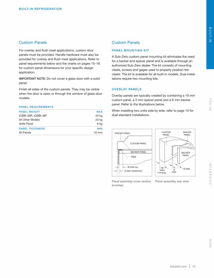
Custom Panels
PANEL MOUNTING KIT
A Sub-Zero custom panel mounting kit eliminates the need for a backer and spacer panel and is avail able through an authorized Sub-Zero dealer. The kit consists of mounting cleats, screws and gages used to properly position the cleats. The kit is available for all built-in models. Dual instal-lations require two mounting kits.
OVERLAY PANELS
Overlay panels are typically created by combining a 19 mm custom panel, a 3 mm spacer panel and a 6 mm backer panel. Refer to the illustrations below.
When installing two units side by side, refer to page 10 for dual standard installations.
3 mm (OVERLAY)
CUSTOM PANEL
SPACER PANEL
BACKER PANEL
TRIM
8 mm min6 mm3
mm
CUSTOMPANEL
SPACERPANEL
BACKERPANEL
19mm
TYPICAL
Panel assembly cross section (overlay).
Panel assembly rear view.
BU
ILT
-IN
PR
O 4
8IN
TE
GR
AT
ED
WIN
E

14 | English
BUILT-IN REFRIGERATION
Custom Panels
FLUSH INSET PANELS
The flush inset application is an overlay model with flush inset panels. It is not a separate model.
The flush inset design allows custom panels to be installed flush with adjacent cabinets. Similar to overlay, flush inset panels are typically created by combining a 19 mm custom panel, a 3 mm spacer panel and a 6 mm backer panel. Refer to the illustrations for overlay panels.
For flush inset panels thicker than 19 mm, a 90° door stop may be required to prevent interference with adjacent cabinets. Refer to the full-scale templates at the end of this guide.
When installing two units side by side, refer to page 11 for dual flush inset installations.
ICE | WATER DISPENSER
For model ICBBI-48SD, the refrigerator door panel must include a cut-out to accommodate the external dispenser. The thickness of the panel in this area can range from 6 mm to a maximum of 29 mm. Refer to the illustrations below.
160 mm
2 mm
3 mmRADIUS
16 mm
327mm
51mm
25mm
HANDLE
GLASSWELL
Dispenser dimensions.
Handle placement.
WIN
EIN
TE
GR
AT
ED
PR
O 4
8B
UIL
T-
IN

subzero.com | 15
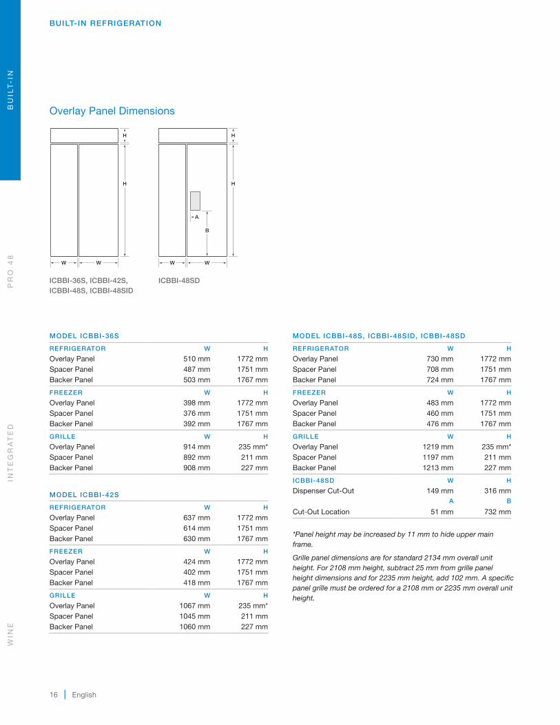
Overlay Panel Dimensions
MODEL ICBBI-36R, ICBBI-36F
REFRIGERATOR | FREEZER W H
Overlay Panel 914 mm 1772 mmSpacer Panel 892 mm 1751 mmBacker Panel 908 mm 1767 mm
GRILLE W H
Overlay Panel 914 mm 235 mm*Spacer Panel 892 mm 211 mmBacker Panel 908 mm 227 mm
MODEL ICBBI-36UID
REFRIGERATOR W H
Overlay Panel 914 mm 1273 mmSpacer Panel 892 mm 1253 mmBacker Panel 908 mm 1268 mm
FREEZER W H
Overlay Panel 914 mm 483 mmSpacer Panel 892 mm 459 mmBacker Panel 908 mm 475 mm
GRILLE W H
Overlay Panel 914 mm 235 mm*Spacer Panel 892 mm 211 mmBacker Panel 908 mm 227 mm
BUILT-IN REFRIGERATION
H
H
H
W
AA
A
A
H
H
W
H
H
W
H
H
W
AA
A
B
H
H
H
W
H
W
H
H
WW
B
A
H
H
W
W W
H
H
H
W
AA
A
A
H
H
W
H
H
W
H
H
W
AA
A
B
H
H
H
W
H
W
H
H
WW
B
A
H
H
W
W W
ICBBI-36R, ICBBI-36F
ICBBI-36UID
BU
ILT
-IN
PR
O 4
8IN
TE
GR
AT
ED
WIN
E
16 | English
Overlay Panel Dimensions
BUILT-IN REFRIGERATION
H
H
H
W
AA
A
A
H
H
W
H
H
W
H
H
W
AA
A
B
H
H
H
W
H
W
H
H
WW
B
A
H
H
W
W W
H
H
H
W
AA
A
A
H
H
W
H
H
W
H
H
W
AA
A
B
H
H
H
W
H
W
H
H
WW
B
A
H
H
W
W W
ICBBI-36S, ICBBI-42S, ICBBI-48S, ICBBI-48SID
ICBBI-48SD
MODEL ICBBI-36S
REFRIGERATOR W H
Overlay Panel 510 mm 1772 mmSpacer Panel 487 mm 1751 mmBacker Panel 503 mm 1767 mm
FREEZER W H
Overlay Panel 398 mm 1772 mmSpacer Panel 376 mm 1751 mmBacker Panel 392 mm 1767 mm
GRILLE W H
Overlay Panel 914 mm 235 mm*Spacer Panel 892 mm 211 mmBacker Panel 908 mm 227 mm
MODEL ICBBI-42S
REFRIGERATOR W H
Overlay Panel 637 mm 1772 mmSpacer Panel 614 mm 1751 mmBacker Panel 630 mm 1767 mm
FREEZER W H
Overlay Panel 424 mm 1772 mmSpacer Panel 402 mm 1751 mmBacker Panel 418 mm 1767 mm
GRILLE W H
Overlay Panel 1067 mm 235 mm*Spacer Panel 1045 mm 211 mmBacker Panel 1060 mm 227 mm
MODEL ICBBI-48S, ICBBI-48SID, ICBBI-48SD
REFRIGERATOR W H
Overlay Panel 730 mm 1772 mmSpacer Panel 708 mm 1751 mmBacker Panel 724 mm 1767 mm
FREEZER W H
Overlay Panel 483 mm 1772 mmSpacer Panel 460 mm 1751 mmBacker Panel 476 mm 1767 mm
GRILLE W H
Overlay Panel 1219 mm 235 mm*Spacer Panel 1197 mm 211 mmBacker Panel 1213 mm 227 mm
ICBBI-48SD W H
Dispenser Cut-Out 149 mm 316 mmA B
Cut-Out Location 51 mm 732 mm
*Panel height may be increased by 11 mm to hide upper main frame.
Grille panel dimensions are for standard 2134 mm overall unit height. For 2108 mm height, subtract 25 mm from grille panel height dimensions and for 2235 mm height, add 102 mm. A specific panel grille must be ordered for a 2108 mm or 2235 mm overall unit height.
WIN
EIN
TE
GR
AT
ED
PR
O 4
8B
UIL
T-
IN

subzero.com | 17
BUILT-IN REFRIGERATION
Flush Inset Panel Dimensions
MODEL ICBBI-36R, ICBBI-36F
REFRIGERATOR | FREEZER W H
Flush Inset Panel 940 mm 1772 mmSpacer Panel 892 mm 1751 mmBacker Panel 908 mm 1767 mm
GRILLE W H
Flush Inset Panel 940 mm 235 mmSpacer Panel 892 mm 211 mmBacker Panel 908 mm 227 mm
MODEL ICBBI-36UID
REFRIGERATOR W H
Flush Inset Panel 940 mm 1273 mmSpacer Panel 892 mm 1253 mmBacker Panel 908 mm 1268 mm
FREEZER W H
Flush Inset Panel 940 mm 483 mmSpacer Panel 892 mm 459 mmBacker Panel 908 mm 475 mm
GRILLE W H
Flush Inset Panel 940 mm 235 mmSpacer Panel 892 mm 211 mmBacker Panel 908 mm 227 mm
H
H
H
W
AA
B
B
H
H
W
H
H
W
H
H
W
AA
A
B
H
H
H
W
H
W
H
H
WW
B
A
H
H
W
W W
H
H
H
W
AA
B
B
H
H
W
H
H
W
H
H
W
AA
A
B
H
H
H
W
H
W
H
H
WW
B
A
H
H
W
W W
ICBBI-36R, ICBBI-36F
ICBBI-36UID
BU
ILT
-IN
PR
O 4
8IN
TE
GR
AT
ED
WIN
E

18 | English
BUILT-IN REFRIGERATION
Flush Inset Panel Dimensions
MODEL ICBBI-36S
REFRIGERATOR W H
Flush Inset Panel 522 mm 1772 mmSpacer Panel 487 mm 1751 mmBacker Panel 503 mm 1767 mm
FREEZER W H
Flush Inset Panel 411 mm 1772 mmSpacer Panel 376 mm 1751 mmBacker Panel 392 mm 1767 mm
GRILLE W H
Flush Inset Panel 940 mm 235 mmSpacer Panel 892 mm 211 mmBacker Panel 908 mm 227 mm
MODEL ICBBI-42S
REFRIGERATOR W H
Flush Inset Panel 649 mm 1772 mmSpacer Panel 614 mm 1751 mmBacker Panel 630 mm 1767 mm
FREEZER W H
Flush Inset Panel 437 mm 1772 mmSpacer Panel 402 mm 1751 mmBacker Panel 418 mm 1767 mm
GRILLE W H
Flush Inset Panel 1092 mm 235 mmSpacer Panel 1045 mm 211 mmBacker Panel 1060 mm 227 mm
MODEL ICBBI-48S, ICBBI-48SID, ICBBI-48SD
REFRIGERATOR W H
Flush Inset Panel 743 mm 1772 mmSpacer Panel 708 mm 1751 mmBacker Panel 724 mm 1767 mm
FREEZER W H
Flush Inset Panel 495 mm 1772 mmSpacer Panel 460 mm 1751 mmBacker Panel 476 mm 1767 mm
GRILLE W H
Flush Inset Panel 1245 mm 235 mmSpacer Panel 1197 mm 211 mmBacker Panel 1213 mm 227 mm
DISPENSER ( ICBBI-48SD) W H
Cut-Out 149 mm 316 mmA B
Cut-Out Location 51 mm 732 mm
Grille panel dimensions are for standard 2134 mm overall unit height. For 2108 mm height, subtract 25 mm from grille panel height dimensions and for 2235 mm height, add 102 mm. A specific panel grille must be ordered for a 2108 mm or 2235 mm overall unit height.
H
H
H
W
AA
A
A
H
H
W
H
H
W
H
H
W
AA
A
B
H
H
H
W
H
W
H
H
WW
B
A
H
H
W
W W
H
H
H
W
AA
A
A
H
H
W
H
H
W
H
H
W
AA
A
B
H
H
H
W
H
W
H
H
WW
B
A
H
H
W
W W
ICBBI-36S, ICBBI-42S, ICBBI-48S, ICBBI-48SID
ICBBI-48SD
WIN
EIN
TE
GR
AT
ED
PR
O 4
8B
UIL
T-
IN
subzero.com | 19
BUILT-IN REFRIGERATION
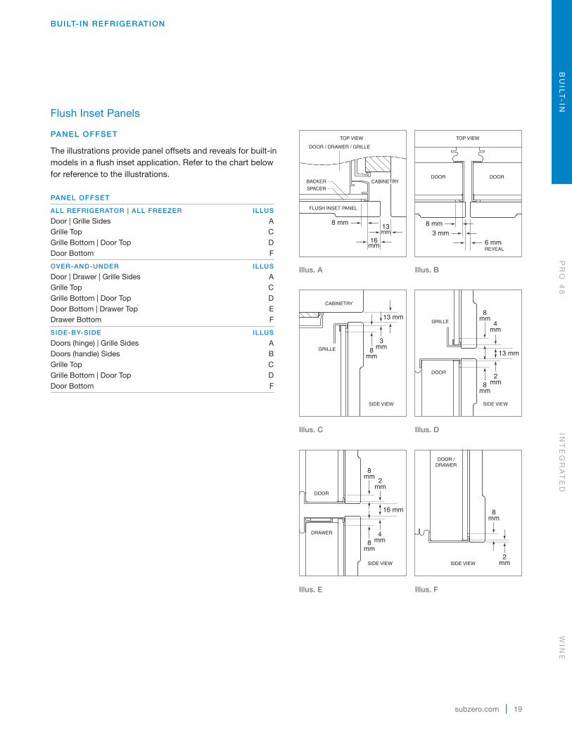
Flush Inset Panels
PANEL OFFSET
The illustrations provide panel offsets and reveals for built-in models in a flush inset application. Refer to the chart below for reference to the illustrations.
PANEL OFFSET
ALL REFRIGERATOR | ALL FREEZER ILLUS
Door | Grille Sides AGrille Top CGrille Bottom | Door Top DDoor Bottom F
OVER-AND-UNDER ILLUS
Door | Drawer | Grille Sides AGrille Top CGrille Bottom | Door Top DDoor Bottom | Drawer Top EDrawer Bottom F
SIDE-BY-SIDE ILLUS
Doors (hinge) | Grille Sides ADoors (handle) Sides BGrille Top CGrille Bottom | Door Top DDoor Bottom F
16mm
16 mm
8 mm13mm
4mm
8mm
8mm
2mm
DOOR
DRAWER
8mm
2mm
DOOR /DRAWER
13 mm
2mm
8mm
8mm
4mm
GRILLE
DOOR
6 mmREVEAL
8 mm3 mm
FLUSH INSET PANEL
SPACER
BACKERDOOR DOOR
DOOR / DRAWER / GRILLE
13 mm
8mm
3mm
CABINETRY
GRILLE
TOP VIEWTOP VIEW
SIDE VIEW SIDE VIEW
SIDE VIEW SIDE VIEW
CABINETRY
16mm
16 mm
8 mm13mm
4mm
8mm
8mm
2mm
DOOR
DRAWER
8mm
2mm
DOOR /DRAWER
13 mm
2mm
8mm
8mm
4mm
GRILLE
DOOR
6 mmREVEAL
8 mm3 mm
FLUSH INSET PANEL
SPACER
BACKERDOOR DOOR
DOOR / DRAWER / GRILLE
13 mm
8mm
3mm
CABINETRY
GRILLE
TOP VIEWTOP VIEW
SIDE VIEW SIDE VIEW
SIDE VIEW SIDE VIEW
CABINETRY
Illus. A
Illus. B
16mm
16 mm
8 mm13mm
4mm
8mm
8mm
2mm
DOOR
DRAWER
8mm
2mm
DOOR /DRAWER
13 mm
2mm
8mm
8mm
4mm
GRILLE
DOOR
6 mmREVEAL
8 mm3 mm
FLUSH INSET PANEL
SPACER
BACKERDOOR DOOR
DOOR / DRAWER / GRILLE
13 mm
8mm
3mm
CABINETRY
GRILLE
TOP VIEWTOP VIEW
SIDE VIEW SIDE VIEW
SIDE VIEW SIDE VIEW
CABINETRY
16mm
16 mm
8 mm13mm
4mm
8mm
8mm
2mm
DOOR
DRAWER
8mm
2mm
DOOR /DRAWER
13 mm
2mm
8mm
8mm
4mm
GRILLE
DOOR
6 mmREVEAL
8 mm3 mm
FLUSH INSET PANEL
SPACER
BACKERDOOR DOOR
DOOR / DRAWER / GRILLE
13 mm
8mm
3mm
CABINETRY
GRILLE
TOP VIEWTOP VIEW
SIDE VIEW SIDE VIEW
SIDE VIEW SIDE VIEW
CABINETRY
Illus. C
Illus. D
16mm
16 mm
8 mm13mm
4mm
8mm
8mm
2mm
DOOR
DRAWER
8mm
2mm
DOOR /DRAWER
13 mm
2mm
8mm
8mm
4mm
GRILLE
DOOR
6 mmREVEAL
8 mm3 mm
FLUSH INSET PANEL
SPACER
BACKERDOOR DOOR
DOOR / DRAWER / GRILLE
13 mm
8mm
3mm
CABINETRY
GRILLE
TOP VIEWTOP VIEW
SIDE VIEW SIDE VIEW
SIDE VIEW SIDE VIEW
CABINETRY
16mm
16 mm
8 mm13mm
4mm
8mm
8mm
2mm
DOOR
DRAWER
8mm
2mm
DOOR /DRAWER
13 mm
2mm
8mm
8mm
4mm
GRILLE
DOOR
6 mmREVEAL
8 mm3 mm
FLUSH INSET PANEL
SPACER
BACKERDOOR DOOR
DOOR / DRAWER / GRILLE
13 mm
8mm
3mm
CABINETRY
GRILLE
TOP VIEWTOP VIEW
SIDE VIEW SIDE VIEW
SIDE VIEW SIDE VIEW
CABINETRY
Illus. E
Illus. F
BU
ILT
-IN
PR
O 4
8IN
TE
GR
AT
ED
WIN
E
20 | English
BUILT-IN REFRIGERATION
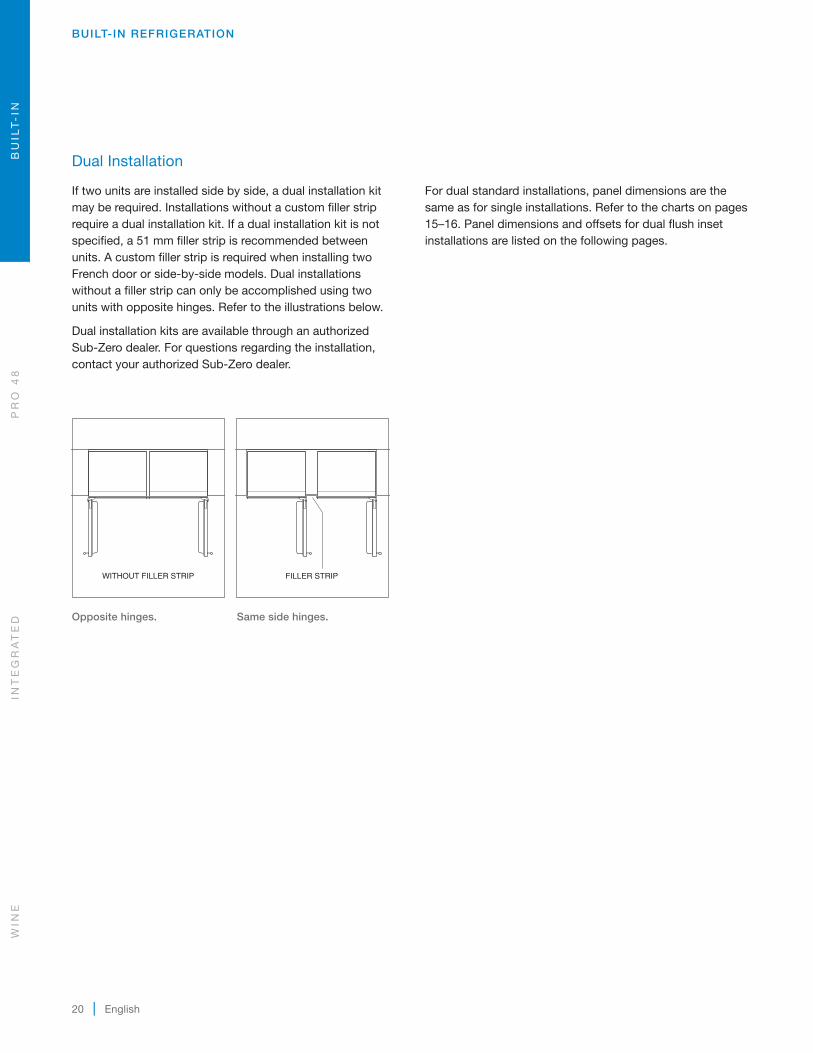
Dual Installation
If two units are installed side by side, a dual installation kit may be required. Installations without a custom filler strip require a dual installation kit. If a dual installation kit is not specified, a 51 mm filler strip is recommended between units. A custom filler strip is required when installing two French door or side-by-side models. Dual installations without a filler strip can only be accomplished using two units with opposite hinges. Refer to the illustrations below.
Dual installation kits are available through an authorized Sub-Zero dealer. For questions regarding the installation, contact your authorized Sub-Zero dealer.
WITHOUT FILLER STRIP FILLER STRIP
Opposite hinges.
Same side hinges.
For dual standard installations, panel dimensions are the same as for single installations. Refer to the charts on pages 15–16. Panel dimensions and offsets for dual flush inset installations are listed on the following pages.
WIN
EIN
TE
GR
AT
ED
PR
O 4
8B
UIL
T-
IN

subzero.com | 21
BUILT-IN REFRIGERATION
Dual Flush Inset Panel Dimensions
MODEL ICBBI-36R, ICBBI-36F
REFRIGERATOR | FREEZER W H
Flush Inset Panel 927 mm 1772 mmSpacer Panel 892 mm 1751 mmBacker Panel 908 mm 1767 mm
GRILLE W H
Flush Inset Panel 927 mm 235 mmSpacer Panel 892 mm 211 mmBacker Panel 908 mm 227 mm
MODEL ICBBI-36UID
REFRIGERATOR W H
Flush Inset Panel 927 mm 1273 mmSpacer Panel 892 mm 1253 mmBacker Panel 908 mm 1268 mm
FREEZER W H
Flush Inset Panel 927 mm 483 mmSpacer Panel 892 mm 459 mmBacker Panel 908 mm 475 mm
GRILLE W H
Flush Inset Panel 927 mm 235 mmSpacer Panel 892 mm 211 mmBacker Panel 908 mm 227 mm
Grille panel dimensions are for standard 2134 mm overall unit height. For 2108 mm height, subtract 25 mm from grille panel height dimensions and for 2235 mm height, add 102 mm. A specific panel grille must be ordered for a 2108 mm or 2235 mm overall unit height. For dual wide grilles, refer to page 23.
H
H
H
W
AA
B
B
H
H
W
H
H
W
H
H
W
AA
A
B
H
H
H
W
H
W
H
H
WW
B
A
H
H
W
W W
H
H
H
W
AA
B
B
H
H
W
H
H
W
H
H
W
AA
A
B
H
H
H
W
H
W
H
H
WW
B
A
H
H
W
W W
ICBBI-36R, ICBBI-36F
ICBBI-36UID
BU
ILT
-IN
PR
O 4
8IN
TE
GR
AT
ED
WIN
E

22 | English
BUILT-IN REFRIGERATION
Dual Installation
DUAL FLUSH INSET PANEL OFFSET
The illustrations provide panel offsets and reveals for built-in models in a dual flush inset application. Refer to the chart below for reference to the illustrations.
PANEL OFFSET
ALL REFRIGERATOR | ALL FREEZER ILLUS
Door (hinge) | Grille Sides ADoor (handle) Sides BGrille Top CGrille Bottom | Door Top DDoor Bottom F
OVER-AND-UNDER ILLUS
Door (hinge) | Drawer | Grille Sides ADoor (handle) Sides BGrille Top CGrille Bottom | Door Top DDoor Bottom | Drawer Top EDrawer Bottom F
16mm
16 mm
8 mm13mm
4mm
8mm
8mm
2mm
DOOR
DRAWER
8mm
2mm
DOOR /DRAWER
13 mm
2mm
8mm
8mm
4mm
GRILLE
DOOR
6 mmREVEAL
8 mm3 mm
FLUSH INSET PANEL
SPACER
BACKERDOOR DOOR
DOOR / DRAWER / GRILLE
13 mm
8mm
3mm
CABINETRY
GRILLE
TOP VIEWTOP VIEW
SIDE VIEW SIDE VIEW
SIDE VIEW SIDE VIEW
CABINETRY
DUALTRIM
6 mmREVEAL
8 mm3 mm
DOOR DOOR
TOP VIEW
Illus. A
Illus. B
16mm
16 mm
8 mm13mm
4mm
8mm
8mm
2mm
DOOR
DRAWER
8mm
2mm
DOOR /DRAWER
13 mm
2mm
8mm
8mm
4mm
GRILLE
DOOR
6 mmREVEAL
8 mm3 mm
FLUSH INSET PANEL
SPACER
BACKERDOOR DOOR
DOOR / DRAWER / GRILLE
13 mm
8mm
3mm
CABINETRY
GRILLE
TOP VIEWTOP VIEW
SIDE VIEW SIDE VIEW
SIDE VIEW SIDE VIEW
CABINETRY
16mm
16 mm
8 mm13mm
4mm
8mm
8mm
2mm
DOOR
DRAWER
8mm
2mm
DOOR /DRAWER
13 mm
2mm
8mm
8mm
4mm
GRILLE
DOOR
6 mmREVEAL
8 mm3 mm
FLUSH INSET PANEL
SPACER
BACKERDOOR DOOR
DOOR / DRAWER / GRILLE
13 mm
8mm
3mm
CABINETRY
GRILLE
TOP VIEWTOP VIEW
SIDE VIEW SIDE VIEW
SIDE VIEW SIDE VIEW
CABINETRY
Illus. C
Illus. D
16mm
16 mm
8 mm13mm
4mm
8mm
8mm
2mm
DOOR
DRAWER
8mm
2mm
DOOR /DRAWER
13 mm
2mm
8mm
8mm
4mm
GRILLE
DOOR
6 mmREVEAL
8 mm3 mm
FLUSH INSET PANEL
SPACER
BACKERDOOR DOOR
DOOR / DRAWER / GRILLE
13 mm
8mm
3mm
CABINETRY
GRILLE
TOP VIEWTOP VIEW
SIDE VIEW SIDE VIEW
SIDE VIEW SIDE VIEW
CABINETRY
16mm
16 mm
8 mm13mm
4mm
8mm
8mm
2mm
DOOR
DRAWER
8mm
2mm
DOOR /DRAWER
13 mm
2mm
8mm
8mm
4mm
GRILLE
DOOR
6 mmREVEAL
8 mm3 mm
FLUSH INSET PANEL
SPACER
BACKERDOOR DOOR
DOOR / DRAWER / GRILLE
13 mm
8mm
3mm
CABINETRY
GRILLE
TOP VIEWTOP VIEW
SIDE VIEW SIDE VIEW
SIDE VIEW SIDE VIEW
CABINETRY
Illus. E
Illus. F
WIN
EIN
TE
GR
AT
ED
PR
O 4
8B
UIL
T-
IN

subzero.com | 23
Dual Installation
DUAL WIDE GRILLE
A dual wide grille spans the entire width of both units in a dual installation and is a part of a dual installation kit.
For overlay and flush inset panel dimensions for the dual wide grille, refer to the charts below. Dimensions listed are for a standard 2134 mm finished height.
DUAL WIDE GRILLE—OVERLAY
TWO 914 mm MODELS W H
Overlay Panel 1835 mm 235 mmSpacer Panel 1813 mm 211 mmBacker Panel 1829 mm 227 mm
DUAL WIDE GRILLE—FLUSH INSET
TWO 914 mm MODELS W H
Flush Inset Panel 1861 mm 235 mmSpacer Panel 1813 mm 211 mmBacker Panel 1829 mm 227 mm
BUILT-IN REFRIGERATION
BU
ILT
-IN
PR
O 4
8IN
TE
GR
AT
ED
WIN
E

24 | English
Side Panel
The custom side panels must be a minimum of 610 mm deep and 13 mm thick. Routing will be necessary for the side panel to fit flush against the side of the unit. Refer to the illustrations below.
When installing a built-in unit with a custom side panel, an accessory kit is required. Stainless steel and white enamel side panels are available through an authorized Sub-Zero dealer.
2134mm
610 mm
ROUT TO5 mm
(OVER-AND-UNDERMODELS)
OPTIONALTOE KICKCUT-OUT
102 mm
521mm
146mm
48 mm
25 mm
108 mm
ROUT TO 3 mm
FRONTOF SIDEPANEL
67mm
MAINFRAME
SIDE PANELROUTING
25 mm48 mm
3 mm
13 mm
Side panel dimensions.
Routing detail.
BUILT-IN REFRIGERATION
Standard Handles
Optional stainless steel tubular and pro handles are avail-able through an authorized Sub-Zero dealer.
Refer to the chart below for standard handle lengths for built-in models.
HANDLE LENGTH TUBULAR PRO
Full Door 1622 mm 1147 mm
Over-and-Under Door 1124 mm 952 mm
914 mm Drawer 770 mm 600 mm
1067 mm Drawer 922 mm 753 mm
WIN
EIN
TE
GR
AT
ED
PR
O 4
8B
UIL
T-
IN
subzero.com | 25
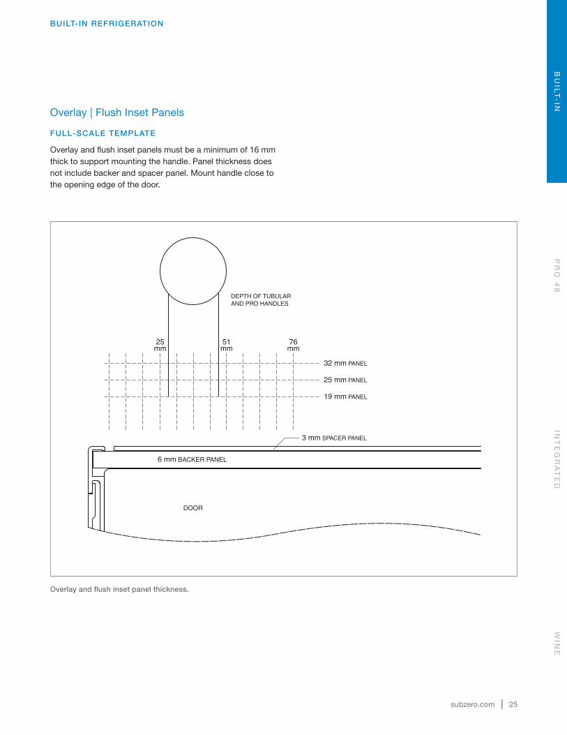
Overlay | Flush Inset Panels
FULL-SCALE TEMPLATE
Overlay and flush inset panels must be a minimum of 16 mm thick to support mounting the handle. Panel thickness does not include backer and spacer panel. Mount handle close to the opening edge of the door.
BUILT-IN REFRIGERATION
Overlay and flush inset panel thickness.
6 mm BACKER PANEL
DOOR
DEPTH OF TUBULARAND PRO HANDLES
25mm
76mm
32 mm PANEL
25 mm PANEL
19 mm PANEL
51mm
3 mm SPACER PANEL
BU
ILT
-IN
PR
O 4
8IN
TE
GR
AT
ED
WIN
E
26 | English
BUILT-IN REFRIGERATION
606 mmTO REAR OF UNIT
OVERALL WIDTH OF UNIT
32 mm
38 mm
44 mm
0 mm
25 mm
51 mm
57 mm
63 mm
70 mm
76 mm
83 mm
89 mm
6 mm
13 mm
19 mm
19 mmTHICK OVERLAY PANEL
(TYPICAL)
6 mmBACKER PANEL
25 mmTHICK PANEL
25 mm0
SCALE
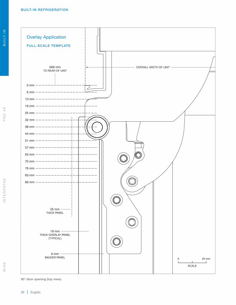
90° door opening (top view).
Overlay Application
FULL-SCALE TEMPLATE
WIN
EIN
TE
GR
AT
ED
PR
O 4
8B
UIL
T-
IN
subzero.com | 27
BUILT-IN REFRIGERATION
32 mm
ASSUMES19 mm
FLUSH INSETPANEL
THICKNESS
56 mm
610 mmTO BACK WALL
19 mmTHICK FLUSH INSET PANEL
(TYPICAL)
6 mmBACKER PANEL
25 mmTHICK PANEL
25 mm0
SCALE
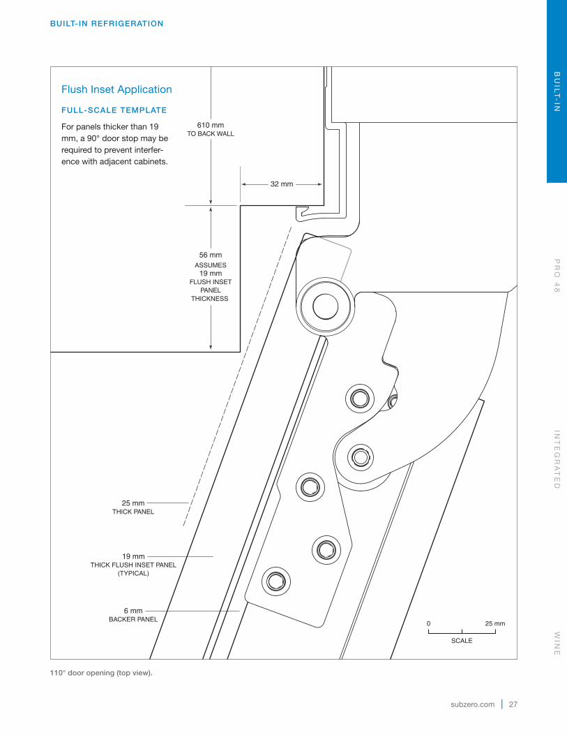
110° door opening (top view).
Flush Inset Application
FULL-SCALE TEMPLATE
For panels thicker than 19 mm, a 90° door stop may be required to prevent interfer-ence with adjacent cabinets.
BU
ILT
-IN
PR
O 4
8IN
TE
GR
AT
ED
WIN
E
28 | English
BUILT-IN REFRIGERATION
32 mm
FILLER STRIP
APPROX PROFILE OFSTAINLESS STEEL WRAPPED
DOOR AND HANDLE
DOOROPEN 110°
DOORCLOSED
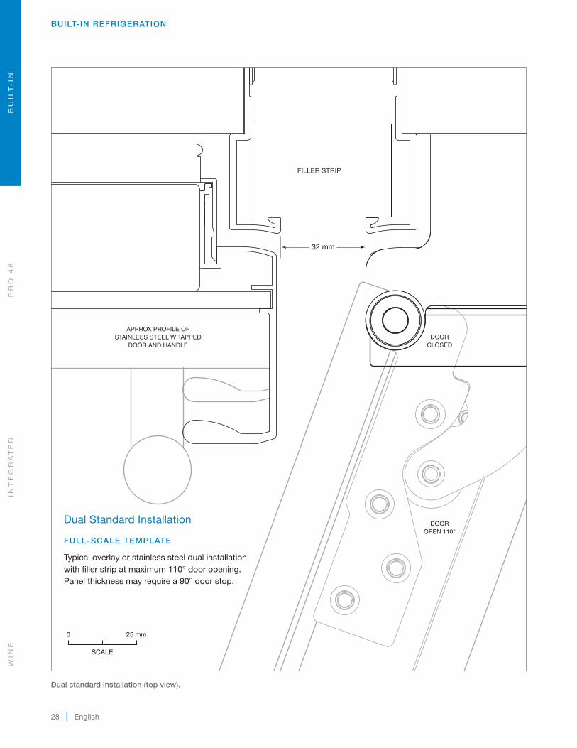
Dual standard installation (top view).
Dual Standard Installation
FULL-SCALE TEMPLATE
Typical overlay or stainless steel dual installation with filler strip at maximum 110° door opening. Panel thickness may require a 90° door stop.
25 mm0
SCALE
WIN
EIN
TE
GR
AT
ED
PR
O 4
8B
UIL
T-
IN

subzero.com | 29
BUILT-IN REFRIGERATION
38 mm
13 mm
FILLER STRIP
PROFILE OF 19 mm FLUSH INSET PANELAND TUBULAR HANDLE
DOORCLOSED
DOOROPEN 110°
Dual flush inset installation (top view).
Dual Flush Inset Installation
FULL-SCALE TEMPLATE
Typical flush inset dual installation with filler strip at maximum 110° door opening. Panel thickness may require a 90° door stop.
25 mm0
SCALE
BU
ILT
-IN
PR
O 4
8IN
TE
GR
AT
ED
WIN
E
30 | English
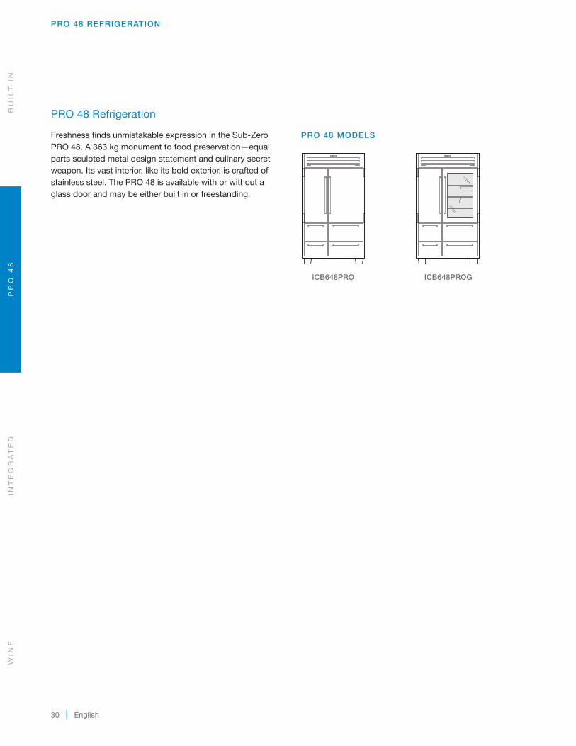
PRO 48 Refrigeration
Freshness finds unmistakable expression in the Sub-Zero PRO 48. A 363 kg monument to food preservation—equal parts sculpted metal design statement and culinary secret weapon. Its vast interior, like its bold exterior, is crafted of stainless steel. The PRO 48 is available with or without a glass door and may be either built in or freestanding.
PRO 48 REFRIGERATION
ICB648PRO
ICB648PROG
PRO 48 MODELS
WIN
EIN
TE
GR
AT
ED
PR
O 4
8B
UIL
T-
IN
subzero.com | 31
PRO 48 REFRIGERATION
2134mm
102 mm
HEIGHT DIMENSIONS ± 13 mm
657 mm
775mm
1070mm
767 mm
368 mm
606mm
781mm
533mm
60 mm
1219 mm
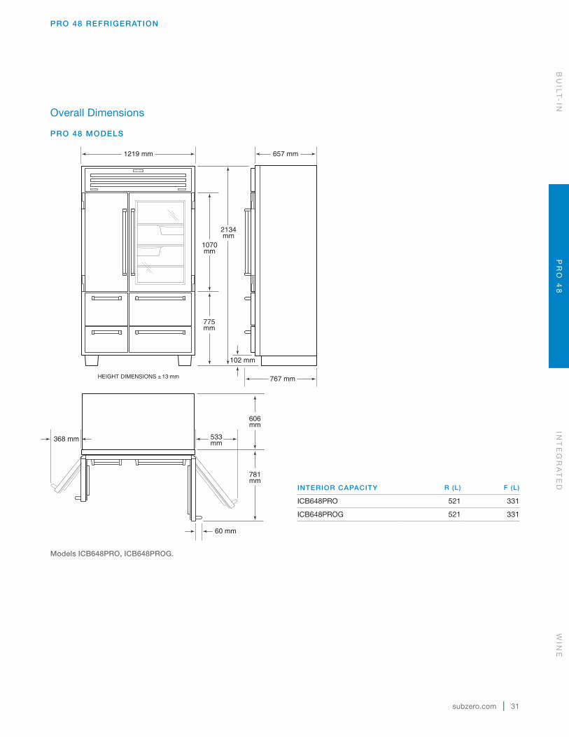
Overall Dimensions
PRO 48 MODELS
Models ICB648PRO, ICB648PROG.
BU
ILT
-IN
PR
O 4
8IN
TE
GR
AT
ED
WIN
E
INTERIOR CAPACITY R (L) F (L)
ICB648PRO 521 331
ICB648PROG 521 331
32 | English
PRO 48 REFRIGERATION
HOPENINGHEIGHT
FRONT VIEWSIDE VIEW
WOPENING WIDTH
DOPENING
DEPTH
TOP VIEW
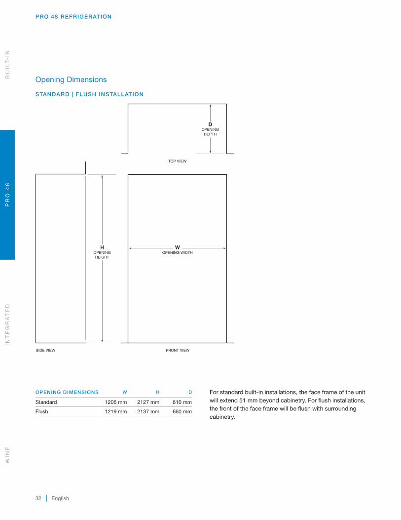
Opening Dimensions
STANDARD | FLUSH INSTALLATION
For standard built-in installations, the face frame of the unit will extend 51 mm beyond cabinetry. For flush installations, the front of the face frame will be flush with surrounding cabinetry.
OPENING DIMENSIONS W H D
Standard 1206 mm 2127 mm 610 mm
Flush 1219 mm 2137 mm 660 mm
WIN
EIN
TE
GR
AT
ED
PR
O 4
8B
UIL
T-
IN

subzero.com | 33
Electrical
International models from the factory designed without a transformer require a 220-240 V AC, 50/60 Hz electrical supply, fused at the correct rating for the unit. If required by local or national codes, the power cord can be easily replaced using the power inlet device.
The electrical supply should be located within the shaded area shown in the illustration below. A separate circuit, ser-vicing only this appliance is required. A ground fault circuit interrupter (GFCI) is not recommended and may cause inter-ruption of operation.
Installation must comply with all applicable electrical codes.
ELECTRICAL REQUIREMENTS
Power Supply 220-240 V AC, 50/60 Hz
Circuit Breaker 1 amp
Receptacle grounding-type (earthed)
Plumbing
The water supply line should be located within the shaded area shown in the illustration below. The water supply line should be connected to the house supply with an easily accessible shut-off valve. Do not use self-piercing valves. The water supply line must not interfere with installation of the anti-tip bracket.
A reverse osmosis system can be used provided there is constant water pressure of 2.4–8.3 bar supplied to the unit at all times. A copper line is not recommended for this application.
Installation must comply with all applicable plumbing codes.
PLUMBING REQUIREMENTS
Water Supply 6.35 mm OD copper line, braided stainless steel, or PEX tubing
Water Pressure 2.4–8.3 bar
Excess Water Line for Connection .9 m
PRO 48 REFRIGERATION
1918 mmFROM FLOOR
178mm E
152mm
RIGHT SIDEOF OPENING
Electrical supply location.
76 mm
152mm
132mm
RIGHT SIDEOF OPENING
AREA EXTENDS 13 mmFORWARD ON FLOOR
Water supply location.
BU
ILT
-IN
PR
O 4
8IN
TE
GR
AT
ED
WIN
E

34 | English
PRO 48 REFRIGERATION
Standard Handles
Refer to the chart below for standard handle lengths for PRO 48 models.
HANDLE LENGTH TUBULAR PRO
Door NA 703 mm
Refrigerator Drawer NA 506 mm
Freezer Drawer NA 294 mm
WIN
EIN
TE
GR
AT
ED
PR
O 4
8B
UIL
T-
IN

subzero.com | 35
INTEGRATED REFRIGERATION
Integrated Refrigeration
With custom front panels and hardware, Sub-Zero invented integrated columns, tall and drawer models that disappear into the decor. Integrated units fit flush with other cabinets, making integrated refrigeration as practical and beautiful in the master suite, bar or theatre room as in the kitchen. Model ICBID-24RO, approved for outdoor installations, is ideal for any outdoor kitchen.
INTEGRATED MODELS
ICBIC-18FI
ICBIC-24R ICBIC-24FI ICBIC-24C
ICBIC-30RID ICBIC-30FI
ICBIC-36RID
ICBIT-30RID ICBIT-30CIID
ICBID-24RO
ICBIT-36CIID
BU
ILT
-IN
PR
O 4
8IN
TE
GR
AT
ED
WIN
E
ICBID-30RP ICBID-30CI
36 | English
INTEGRATED REFRIGERATION
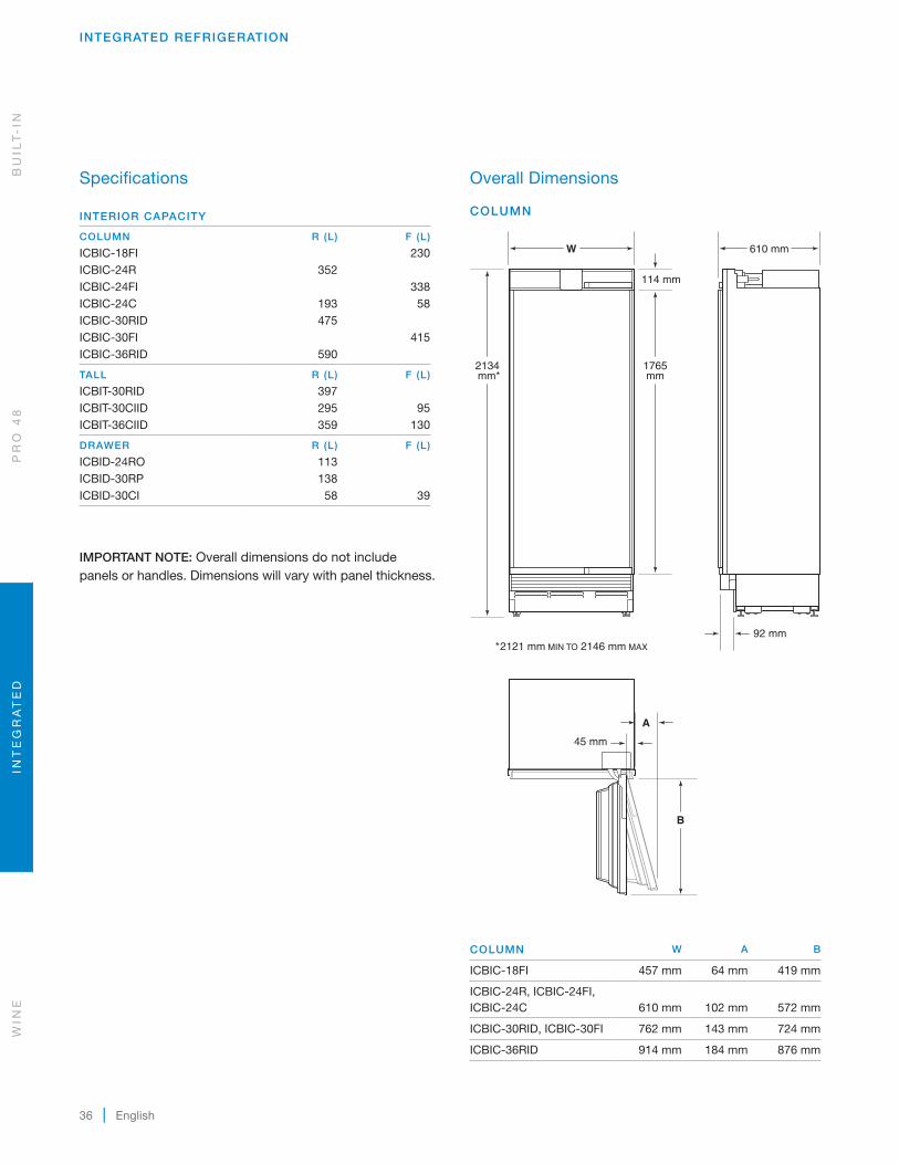
Overall Dimensions
COLUMN
1765mm
W 610 mm
2134 mm*
114 mm
92 mm*2121 mm MIN TO 2146 mm MAX
A
B
45 mm
COLUMN W A B
ICBIC-18FI 457 mm 64 mm 419 mm
ICBIC-24R, ICBIC-24FI, ICBIC-24C
610 mm
102 mm
572 mm
ICBIC-30RID, ICBIC-30FI 762 mm 143 mm 724 mm
ICBIC-36RID 914 mm 184 mm 876 mm
Specifications
INTERIOR CAPACITY
COLUMN R (L) F (L)
ICBIC-18FI 230ICBIC-24R 352ICBIC-24FI 338ICBIC-24C 193 58ICBIC-30RID 475ICBIC-30FI 415ICBIC-36RID 590
TALL R (L) F (L)
ICBIT-30RID 397ICBIT-30CIID 295 95ICBIT-36CIID 359 130
DRAWER R (L) F (L)
ICBID-24RO 113ICBID-30RP 138ICBID-30CI 58 39
IMPORTANT NOTE: Overall dimensions do not include panels or handles. Dimensions will vary with panel thickness.
WIN
EIN
TE
GR
AT
ED
PR
O 4
8B
UIL
T-
IN

subzero.com | 37
INTEGRATED REFRIGERATION
Overall Dimensions
TALL DRAWER
467mm
W 610 mm
2134 mm*
268mm
1140mm
338mm
114 mm
92 mm*2121 mm MIN TO 2146 mm MAX
10 mm
A
B
45 mm
10 mm
W
467mm
610 mm
6 mm
876 mm* 268
mm
338mm
10 mm
92 mm*864 mm MIN TO 889 mm MAX
TALL W A B
ICBIT-30RID, ICBIT-30CIID 762 mm 143 mm 724 mm
ICBIT-36CIID 914 mm 184 mm 876 mm
DRAWER W
ICBID-24RO 610 mm
ICBID-30RP, ICBID-30CI 762 mm
BU
ILT
-IN
PR
O 4
8IN
TE
GR
AT
ED
WIN
E
38 | English
INTEGRATED REFRIGERATION
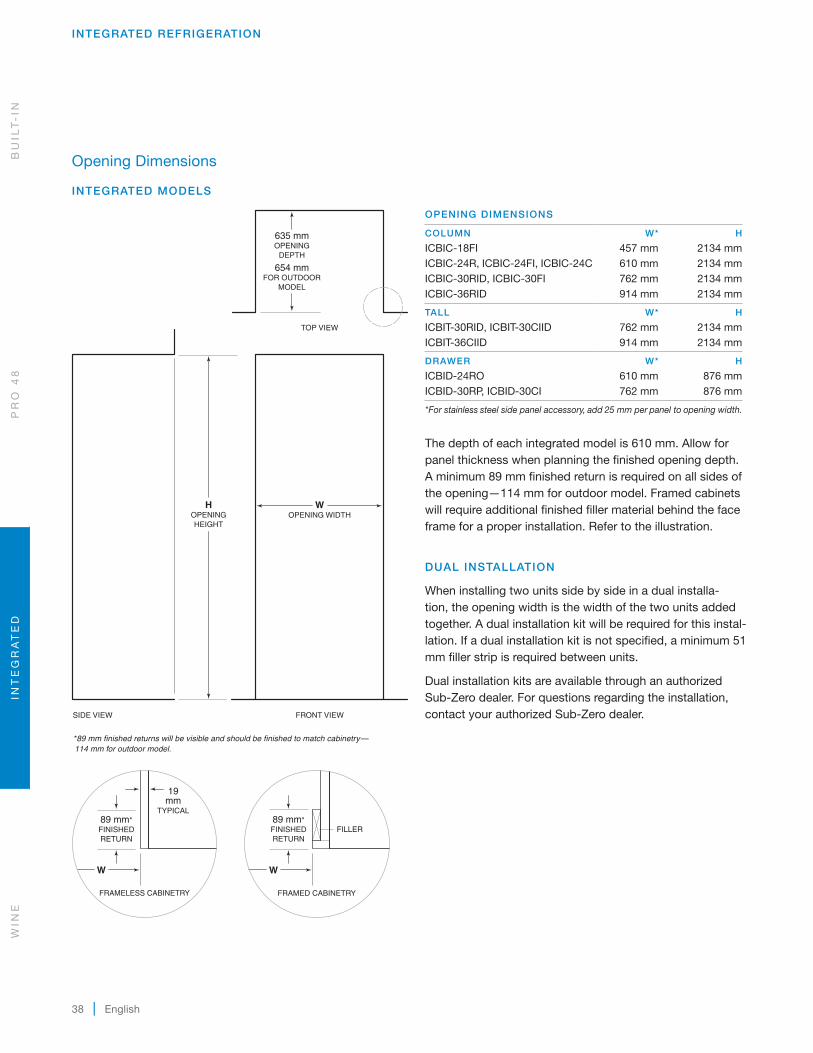
Opening Dimensions
INTEGRATED MODELS
635 mmOPENING
DEPTH
654 mmFOR OUTDOOR
MODEL
WOPENING WIDTH
HOPENINGHEIGHT
*89 mm finished returns will be visible and should be finished to match cabinetry— 114 mm for outdoor model.
SIDE VIEW
TOP VIEW
FRONT VIEW
89 mm*FINISHEDRETURN
FRAMELESS CABINETRY
19mm
TYPICAL89 mm*FINISHEDRETURN
FILLER
FRAMED CABINETRY
W W
OPENING DIMENSIONS
COLUMN W* H
ICBIC-18FI 457 mm 2134 mmICBIC-24R, ICBIC-24FI, ICBIC-24C 610 mm 2134 mmICBIC-30RID, ICBIC-30FI 762 mm 2134 mmICBIC-36RID 914 mm 2134 mm
TALL W* H
ICBIT-30RID, ICBIT-30CIID 762 mm 2134 mmICBIT-36CIID 914 mm 2134 mm
DRAWER W* H
ICBID-24RO 610 mm 876 mmICBID-30RP, ICBID-30CI 762 mm 876 mm
*For stainless steel side panel accessory, add 25 mm per panel to opening width.
The depth of each integrated model is 610 mm. Allow for panel thickness when planning the finished opening depth. A minimum 89 mm finished return is required on all sides of the opening—114 mm for outdoor model. Framed cabinets will require additional finished filler material behind the face frame for a proper installation. Refer to the illustration.
DUAL INSTALLATION
When installing two units side by side in a dual installa-tion, the opening width is the width of the two units added together. A dual installation kit will be required for this instal-lation. If a dual installation kit is not specified, a minimum 51 mm filler strip is required between units.
Dual installation kits are available through an authorized Sub-Zero dealer. For questions regarding the installation, contact your authorized Sub-Zero dealer.
WIN
EIN
TE
GR
AT
ED
PR
O 4
8B
UIL
T-
IN

subzero.com | 39
INTEGRATED REFRIGERATION
76 mm
152mm
RIGHT SIDEOF OPENING
AREA EXTENDS 13 mmFORWARD ON FLOOR
A
Water supply location.
Electrical
The electrical supply must be located within the shaded area shown in the illustration and chart below. A separate circuit, servicing only this appliance is required.
IMPORTANT NOTE: For indoor models, a ground fault circuit interrupter (GFCI) is not recommended and may cause inter-ruption of operation.
For the outdoor model, a ground fault circuit interrupter (GFCI) is required to reduce the risk of electrical shock.
Installation must comply with all applicable electrical codes.
ELECTRICAL REQUIREMENTS
Power Supply 220-240 V AC, 50/60 Hz
Circuit Breaker 10 amp
Receptacle grounding-type (earthed)
ELECTRICAL SUPPLY LOCATION A
457 mm Model 152 mm
610 mm Model 241 mm
762 mm Model 318 mm
914 mm Model 394 mm
A
6 mm
108mm
114mm
FLOOR
LEFT SIDEOF OPENING
E
Electrical supply location.
Plumbing
The water supply line should be located within the shaded area shown in the illustration below. The water supply line should be connected to the house supply with an easily accessible shut-off valve. Do not use self-piercing valves. The water supply line must not interfere with installation of the anti-tip bracket.
A reverse osmosis system can be used provided there is constant water pressure of 2.4–8.3 bar supplied to the unit at all times. A copper line is not recommended for this application.
Installation must comply with all applicable plumbing codes.
PLUMBING REQUIREMENTS
Water Supply Line 6.35 mm OD copper line, braided stainless steel, or PEX tubing
Water Pressure 2.4–8.3 bar
Excess Water Line for Connection .9 m
WATER SUPPLY LOCATION A
457 mm Model 76 mm
610 mm Model 140 mm
762 mm Model 152 mm
914 mm Model 229 mm
BU
ILT
-IN
PR
O 4
8IN
TE
GR
AT
ED
WIN
E
40 | English
INTEGRATED REFRIGERATION
Stainless Steel Panels
The outdoor model requires the use of Sub-Zero stainless steel outdoor accessory panels. Stainless steel panels are available through an authorized Sub-Zero dealer. For local dealer information, visit the find a showroom section of our website, subzero.com.
The thickness of indoor stainless steel panels is 19 mm and outdoor stainless steel panels are 38 mm. The depth of each integrated model is 610 mm. Allow for panel thickness when planning the finished opening depth.
3 mm reveals are typical, however, the reveal between the upper and lower outdoor stainless steel panels is 6 mm to accommodate the lock.
WIN
EIN
TE
GR
AT
ED
PR
O 4
8B
UIL
T-
IN
Custom Panels
For integrated models, custom door panels and handle hardware must be provided. Refer to the panel requirements chart and typical panel dimensions.
The thickness of the custom panel can vary. A minimum 16 mm thick panel is required, but the thickness can be increased provided it does not exceed the weight limit. The depth of each integrated model is 610 mm. Allow for panel thickness when planning the finished opening depth. Refer to the full-scale template on page 43.
CAUTION
As reveals between cabinetry and the unit decrease, severe finger pinching can occur while door is closing.
Finish all sides of custom panels. They will be visible when the door/drawer is open.
D-style handles are recommended. Door handles must be located near the edge of the panel opposite the hinge and should be centered top to bottom. Drawer handles must be located near the top edge of each panel. Stainless steel tubular and pro handles are avail able through an authorized Sub-Zero dealer.
PANEL REQUIREMENTS
COLUMN MAX WEIGHT
457 mm Model 20 kg610 mm Model 27 kg762 mm Model 34 kg914 mm Model 34 kg
TALL (DOOR) MAX WEIGHT
762 mm Model 22 kg914 mm Model 27 kg
DRAWER MAX WEIGHT
Drawer Panel 7 kg
PANEL THICKNESS MINIMUM
All Panels 16 mm
subzero.com | 41
INTEGRATED REFRIGERATION
Custom Panels
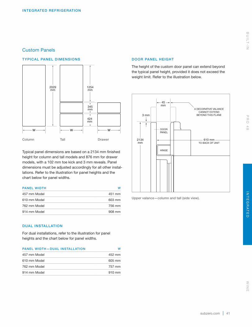
TYPICAL PANEL DIMENSIONS
Typical panel dimensions are based on a 2134 mm finished height for column and tall models and 876 mm for drawer models, with a 102 mm toe kick and 3 mm reveals. Panel dimensions must be adjusted accordingly for all other instal-lations. Refer to the illustration for panel heights and the chart below for panel widths.
PANEL WIDTH W
457 mm Model 451 mm
610 mm Model 603 mm
762 mm Model 756 mm
914 mm Model 908 mm
DUAL INSTALLATION
For dual installations, refer to the illustration for panel heights and the chart below for panel widths.
PANEL WIDTH—DUAL INSTALLATION W
457 mm Model 452 mm
610 mm Model 605 mm
762 mm Model 757 mm
914 mm Model 910 mm
W
1254mm
345mm
424mm
WW
2029mm
Column
Tall
Drawer
DOOR PANEL HEIGHT
The height of the custom door panel can extend beyond the typical panel height, provided it does not exceed the weight limit. Refer to the illustration below.
45mm
A DECORATIVE VALANCECANNOT EXTEND
BEYOND THIS PLANE
DOORPANEL
HINGE
610 mmTO BACK OF UNIT
2134mm
3 mm
Upper valance—column and tall (side view).
BU
ILT
-IN
PR
O 4
8IN
TE
GR
AT
ED
WIN
E
42 | English
INTEGRATED REFRIGERATION
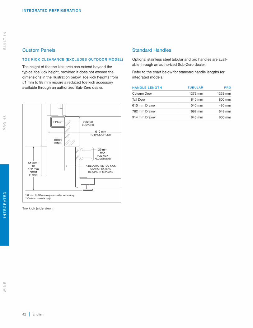
Standard Handles
Optional stainless steel tubular and pro handles are avail-able through an authorized Sub-Zero dealer.
Refer to the chart below for standard handle lengths for integrated models.
HANDLE LENGTH TUBULAR PRO
Column Door 1273 mm 1229 mm
Tall Door 845 mm 800 mm
610 mm Drawer 540 mm 495 mm
762 mm Drawer 692 mm 648 mm
914 mm Drawer 845 mm 800 mm
WIN
EIN
TE
GR
AT
ED
PR
O 4
8B
UIL
T-
IN
Custom Panels
TOE KICK CLEARANCE (EXCLUDES OUTDOOR MODEL)
The height of the toe kick area can extend beyond the typical toe kick height, provided it does not exceed the dimensions in the illustration below. Toe kick heights from 51 mm to 98 mm require a reduced toe kick accessory available through an authorized Sub-Zero dealer.
610 mmTO BACK OF UNIT
VENTEDLOUVERS
HINGE**
DOORPANEL
29 mmMAX
TOE KICK ADJUSTMENT
A DECORATIVE TOE KICKCANNOT EXTEND
BEYOND THIS PLANE
51 mm*TO
152 mmFROMFLOOR
*51 mm to 98 mm requires sales accessory.**Column models only.
Toe kick (side view).
subzero.com | 43
INTEGRATED REFRIGERATION
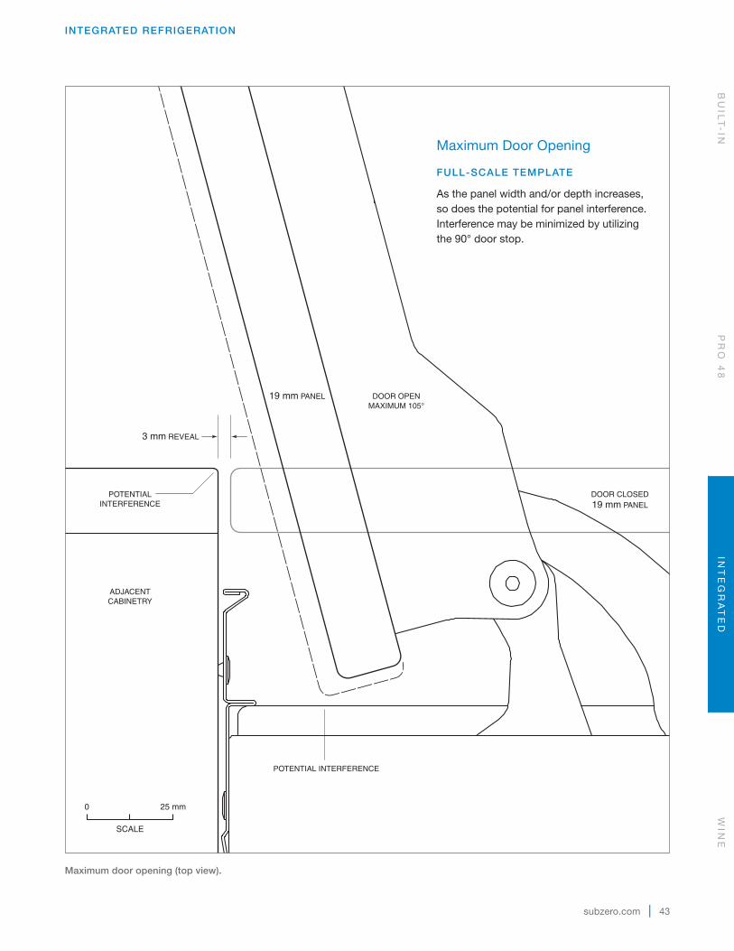
DOOR CLOSED19 mm PANEL
POTENTIALINTERFERENCE
ADJACENTCABINETRY
DOOR OPENMAXIMUM 105°
POTENTIAL INTERFERENCE
3 mm REVEAL
19 mm PANEL
Maximum door opening (top view).
Maximum Door Opening
FULL-SCALE TEMPLATE
As the panel width and/or depth increases, so does the potential for panel interference. Interference may be minimized by utilizing the 90° door stop.
25 mm0
SCALE
BU
ILT
-IN
PR
O 4
8IN
TE
GR
AT
ED
WIN
E
44 | English
WINE STORAGE
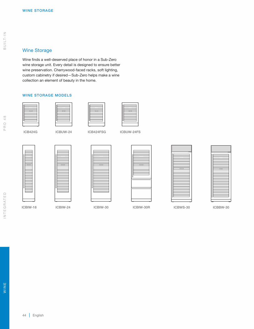
Wine Storage
Wine finds a well-deserved place of honor in a Sub-Zero wine storage unit. Every detail is designed to ensure better wine preservation. Cherrywood-faced racks, soft lighting, custom cabinetry if desired—Sub-Zero helps make a wine collection an element of beauty in the home.
WINE STORAGE MODELS
ICB424G
ICB424FSG
ICBIW-18
ICBIW-24
ICBIW-30
ICBIW-30R
ICBWS-30
ICBUW-24
ICBUW-24FS
ICBBW-30
WIN
EIN
TE
GR
AT
ED
PR
O 4
8B
UIL
T-
IN

subzero.com | 45
WINE STORAGE
606 mm 610 mm
864mm
645mm
44 mm
102 mm
Overall Dimensions
MODEL ICB424G | ICBUW-24
STORAGE CAPACITY BOTTLES (750 ML)
ICB424G, ICBUW-24 46
ICB424FSG, ICBUW-24FS 46
MODEL ICB424FSG | ICBUW-24FS
645mm
44 mm
616 mm 625 mm
868mm
102 mm
Freestanding models ICB424FSG ICBUW-24FS have a finished stainless steel exterior and handles.
Overall dimensions for ICB424G and ICBUW-24 are based on the stainless steel model. Refer to page 65 for door clearance information.
BU
ILT
-IN
PR
O 4
8IN
TE
GR
AT
ED
WIN
E
46 | English
WINE STORAGE
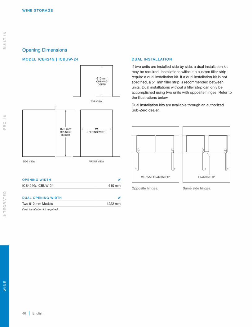
Opening Dimensions
MODEL ICB424G | ICBUW-24
OPENING WIDTH W
ICB424G, ICBUW-24 610 mm
DUAL OPENING WIDTH W
Two 610 mm Models 1222 mm
Dual installation kit required.
WOPENING WIDTH
876 mmOPENINGHEIGHT
610 mmOPENING
DEPTH
TOP VIEW
SIDE VIEW FRONT VIEW
DUAL INSTALLATION
If two units are installed side by side, a dual installation kit may be required. Installations without a custom filler strip require a dual installation kit. If a dual installation kit is not specified, a 51 mm filler strip is recommended between units. Dual installations without a filler strip can only be accomplished using two units with opposite hinges. Refer to the illustrations below.
Dual installation kits are available through an authorized Sub-Zero dealer.
WITHOUT FILLER STRIP FILLER STRIP
Opposite hinges.
Same side hinges.
WIN
EIN
TE
GR
AT
ED
PR
O 4
8B
UIL
T-
IN
subzero.com | 47
WINE STORAGE
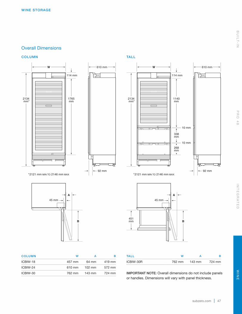
Overall Dimensions
COLUMN
1765mm
W 610 mm
2134 mm*
114 mm
92 mm*2121 mm MIN TO 2146 mm MAX
A
B
45 mm
TALL
451mm
W 610 mm
2134 mm*
268mm
1140mm
338mm
114 mm
92 mm*2121 mm MIN TO 2146 mm MAX
10 mm
10 mm
A
B
45 mm
TALL W A B
ICBIW-30R 762 mm 143 mm 724 mm
IMPORTANT NOTE: Overall dimensions do not include panels or handles. Dimensions will vary with panel thickness.
COLUMN W A B
ICBIW-18 457 mm 64 mm 419 mm
ICBIW-24 610 mm 102 mm 572 mm
ICBIW-30 762 mm 143 mm 724 mm
BU
ILT
-IN
PR
O 4
8IN
TE
GR
AT
ED
WIN
E

48 | English
WINE STORAGE
Specifications
INTERIOR CAPACITY
COLUMN BOTTLES (750 ML)
ICBIW-18 59ICBIW-24 102ICBIW-30 146
TALL R (L) BOTTLES (750 ML)
ICBIW-30R 113 86
WIN
EIN
TE
GR
AT
ED
PR
O 4
8B
UIL
T-
IN
subzero.com | 49
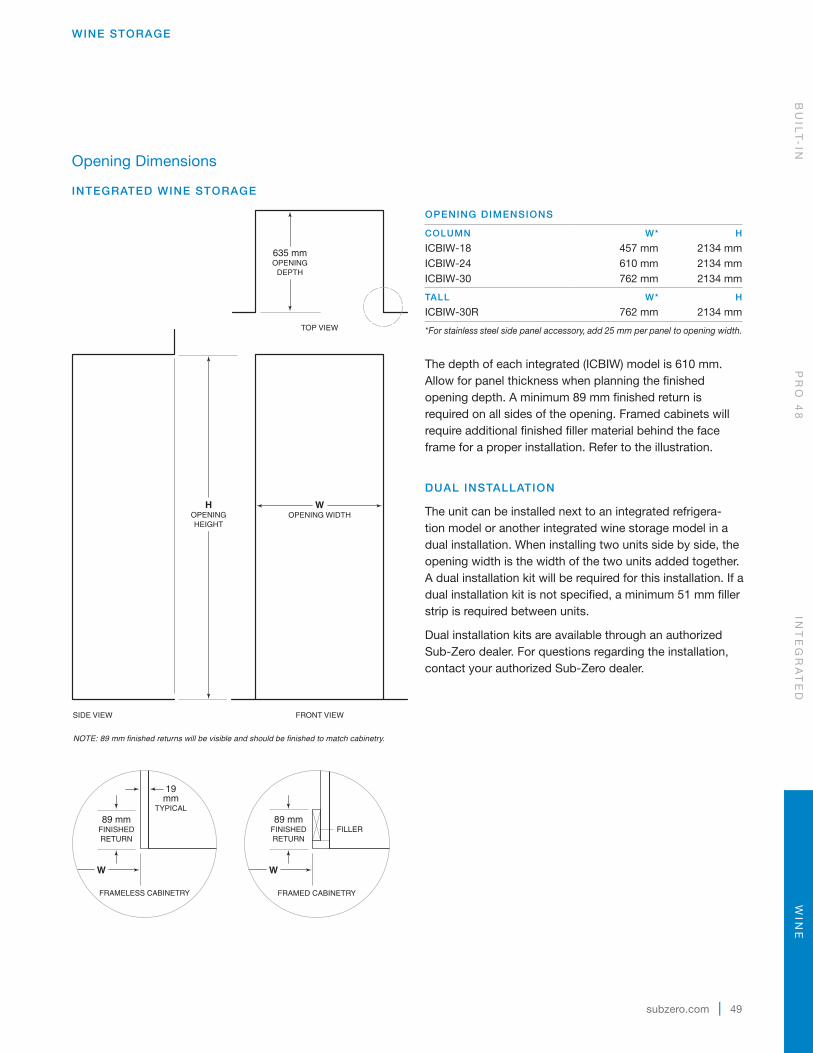
WINE STORAGE
Opening Dimensions
INTEGRATED WINE STORAGE
OPENING DIMENSIONS
COLUMN W* H
ICBIW-18 457 mm 2134 mmICBIW-24 610 mm 2134 mmICBIW-30 762 mm 2134 mm
TALL W* H
ICBIW-30R 762 mm 2134 mm
*For stainless steel side panel accessory, add 25 mm per panel to opening width.
The depth of each integrated (ICBIW) model is 610 mm. Allow for panel thickness when planning the finished opening depth. A minimum 89 mm finished return is required on all sides of the opening. Framed cabinets will require additional finished filler material behind the face frame for a proper installation. Refer to the illustration.
DUAL INSTALLATION
The unit can be installed next to an integrated refrigera-tion model or another integrated wine storage model in a dual installation. When installing two units side by side, the opening width is the width of the two units added together. A dual installation kit will be required for this installation. If a dual installation kit is not specified, a minimum 51 mm filler strip is required between units.
Dual installation kits are available through an authorized Sub-Zero dealer. For questions regarding the installation, contact your authorized Sub-Zero dealer.
635 mmOPENING
DEPTH
WOPENING WIDTH
HOPENINGHEIGHT
NOTE: 89 mm finished returns will be visible and should be finished to match cabinetry.
SIDE VIEW
TOP VIEW
FRONT VIEW
89 mmFINISHEDRETURN
FRAMELESS CABINETRY
19mm
TYPICAL
89 mmFINISHEDRETURN
FILLER
FRAMED CABINETRY
W W
BU
ILT
-IN
PR
O 4
8IN
TE
GR
AT
ED
WIN
E

50 | English
WINE STORAGE
Opening Dimensions
ICBWS-30 | ICBBW-30 STANDARD INSTALLATION
OPENING WIDTH W
ICBWS-30 749 mm
ICBBW-30 749 mm
If a 2108 mm grille height is specified, the opening height must be decreased by 22 mm. If a 2235 mm grille height is specified, the opening height must be increased by 102 mm.
If two units are installed side by side, refer to page 52 for dual standard installations.
762 mm
2134mm
102 mm
1873mm
606mm
796mm
432mm
606 mm
60 mm
HEIGHT DIMENSIONS ± 13 mm
665 mm
Overall Dimensions
MODEL ICBWS-30 | ICBBW-30
STORAGE CAPACITY BOTTLES (750 ML)
ICBWS-30 147
ICBBW-30 146
Overall dimensions are based on the stainless steel model. For flush inset applications, add 13 mm to door clearance dimensions.
2127 mmOPENINGHEIGHT
610 mmOPENING
DEPTH
NOTE: Shaded line represents profile of unit.
FRONT VIEWSIDE VIEW
TOP VIEW
WOPENING WIDTH
WIN
EIN
TE
GR
AT
ED
PR
O 4
8B
UIL
T-
IN
subzero.com | 51
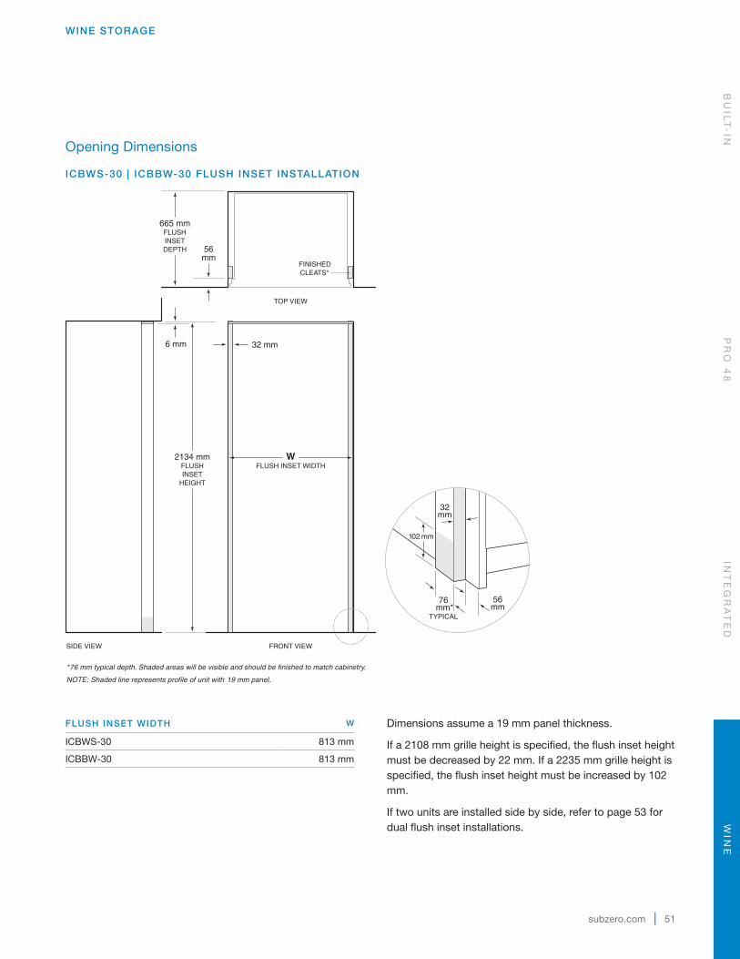
WINE STORAGE
Opening Dimensions
ICBWS-30 | ICBBW-30 FLUSH INSET INSTALLATION
FLUSH INSET WIDTH W
ICBWS-30 813 mm
ICBBW-30 813 mm
Dimensions assume a 19 mm panel thickness.
If a 2108 mm grille height is specified, the flush inset height must be decreased by 22 mm. If a 2235 mm grille height is specified, the flush inset height must be increased by 102 mm.
If two units are installed side by side, refer to page 53 for dual flush inset installations.
2134 mmFLUSHINSET
HEIGHT
6 mm
665 mmFLUSHINSETDEPTH 56
mm
*76 mm typical depth. Shaded areas will be visible and should be finished to match cabinetry.
NOTE: Shaded line represents profile of unit with 19 mm panel.
FRONT VIEWSIDE VIEW
TOP VIEW
FINISHEDCLEATS*
32 mm
WFLUSH INSET WIDTH
102 mm
32mm
56mm
76 mm*
TYPICAL
BU
ILT
-IN
PR
O 4
8IN
TE
GR
AT
ED
WIN
E
52 | English
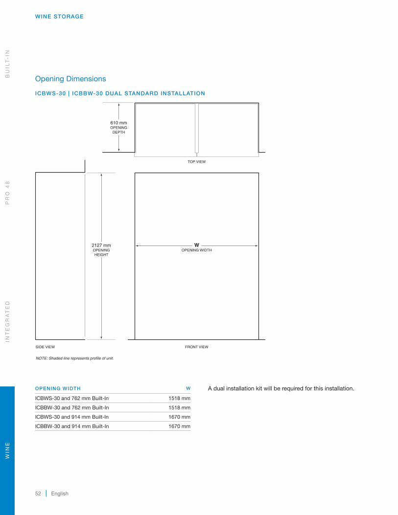
Opening Dimensions
ICBWS-30 | ICBBW-30 DUAL STANDARD INSTALLATION
2127 mmOPENINGHEIGHT
610 mmOPENING
DEPTH
NOTE: Shaded line represents profile of unit.
FRONT VIEWSIDE VIEW
TOP VIEW
WOPENING WIDTH
OPENING WIDTH W
ICBWS-30 and 762 mm Built-In 1518 mm
ICBBW-30 and 762 mm Built-In 1518 mm
ICBWS-30 and 914 mm Built-In 1670 mm
ICBBW-30 and 914 mm Built-In 1670 mm
A dual installation kit will be required for this installation.
WINE STORAGE
WIN
EIN
TE
GR
AT
ED
PR
O 4
8B
UIL
T-
IN

subzero.com | 53
Opening Dimensions
ICBWS-30 | ICBBW-30 DUAL FLUSH INSET INSTALLATION
2134 mmFLUSHINSET
HEIGHT
6 mm
665 mmFLUSHINSETDEPTH 56
mm
*76 mm typical depth. Shaded areas will be visible and should be finished to match cabinetry.
NOTE: Shaded line represents profile of unit with19 mm panel.
FRONT VIEWSIDE VIEW
TOP VIEW
FINISHEDCLEATS*
32 mm
WFLUSH INSET WIDTH
102 mm
32mm
56mm
76 mm*
TYPICAL
FLUSH INSET WIDTH W
ICBWS-30 and 762 mm Built-In 1581 mm
ICBBW-30 and 762 mm Built-In 1581 mm
ICBWS-30 and 914 mm Built-In 1734 mm
ICBBW-30 and 914 mm Built-In 1734 mm
Dimensions assume a 19 mm panel thickness. A dual instal-lation kit will be required for this installation.
WINE STORAGE
BU
ILT
-IN
PR
O 4
8IN
TE
GR
AT
ED
WIN
E

54 | English
ELECTRICAL SUPPLY LOCATION A
ICBIW-18 152 mm
ICBIW-24 241 mm
ICBIW-30, ICBIW 30R 318 mm
Electrical
The electrical supply must be located within the shaded area shown in the illustration for your specific model. For integrated (ICBIW) models, also refer to the chart. A separate circuit, servicing only this appliance is required. A ground fault circuit interrupter (GFCI) is not recommended and may cause interruption of operation.
If the unit will be connected to a home security system, allow 914 mm of excess wiring for proper connection.
Installation must comply with all applicable electrical codes.
ELECTRICAL REQUIREMENTS
Power Supply 220-240 V AC, 50/60 Hz
Circuit Breaker 10 amp
Receptacle grounding-type (earthed)
WINE STORAGE
76 mm
394 mm51mm
LEFT SIDEOF OPENING
FLOOR
E
1918 mmFROM FLOOR
178mm E
152mm
RIGHT SIDEOF OPENING
Model ICB424G, ICBUW-24.
Model ICBWS-30, ICBBW-30.
A
6 mm
108mm
114mm
FLOOR
LEFT SIDEOF OPENING
E
Integrated (ICBIW) models.
WIN
EIN
TE
GR
AT
ED
PR
O 4
8B
UIL
T-
IN

subzero.com | 55
Custom Panels—ICB424G | ICBUW-24
For models ICB424G and ICBUW-24, the custom door panel will attach directly to the door frame with screws through a series of pre-drilled holes.
Refer to the charts for panel requirements and dimensions.
PANEL REQUIREMENTS
PANEL WEIGHT MAX
ICB424G, ICBUW-24 5 kg
PANEL THICKNESS MIN
ICB424G, ICBUW-24 16 mm
OVERLAY PANEL DIMENSIONS
H
W
A A
A
A
ICB424G, ICBUW-24
PANEL DIMENSIONS
MODEL W H
ICB424G, ICBUW-24 603 mm 764 mm
STILES | RAILS A
Minimum 57 mm
DOOR CLEARANCE
Models ICB424G and ICBUW-24 can be installed flush with surrounding cabinetry. Depending on the thickness of the overlay door panel, it may be necessary to install the unit 6 mm beyond the front surface of adjacent cabinetry to prevent interference when the door is opened to 145°. Refer to the full-scale template on page 65.
Custom Panels
For overlay, integrated and flush inset applications, custom door panels must be provided. Handle hardware must also be provided for overlay, integrated and flush inset applica-tions. Refer to panel requirements and custom panel dimen-sions charts for your specific model and design application.
Do not install a solid panel on a glass door unit. A solid door is available as a sales accessory (except models ICBWS-30 and ICBBW-30) and must be installed if a solid panel is being specified. Service may be required to install the door. Contact an authorized Sub-Zero dealer for more informa-tion. Overall dimensions are the same for glass and solid door panels.
Finish all sides of the custom panels. They may be visible when the door is open or through the window of glass door models.
Models ICB424FSG and ICBUW-24FS have a finished stainless steel exterior that is designed to be used in a free-standing application.
WINE STORAGE
BU
ILT
-IN
PR
O 4
8IN
TE
GR
AT
ED
WIN
E
56 | English
WINE STORAGE
TYPICAL PANEL DIMENSIONS
W
1254mm
345mm
424mm
W
2029mm
Column
Tall
Custom Panels—Integrated Models
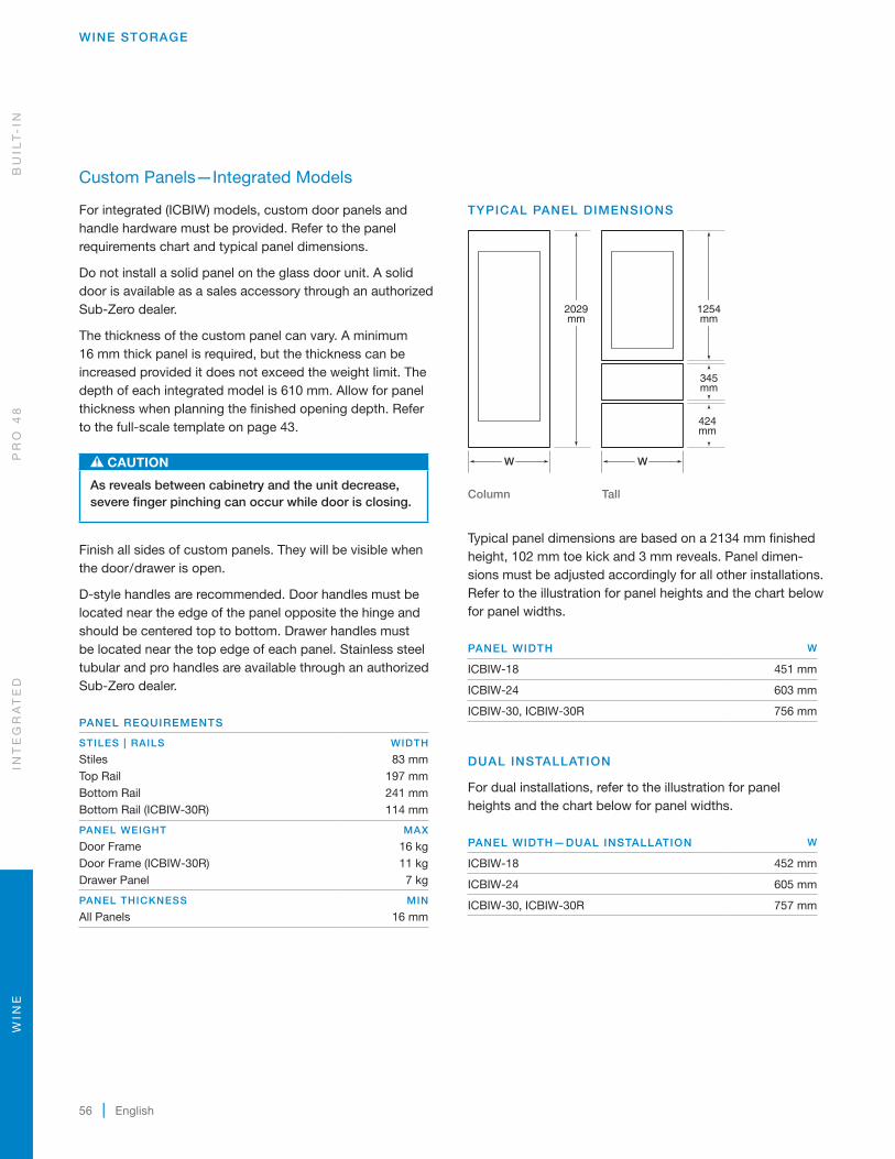
For integrated (ICBIW) models, custom door panels and handle hardware must be provided. Refer to the panel requirements chart and typical panel dimensions.
Do not install a solid panel on the glass door unit. A solid door is available as a sales accessory through an authorized Sub-Zero dealer.
The thickness of the custom panel can vary. A minimum 16 mm thick panel is required, but the thickness can be increased provided it does not exceed the weight limit. The depth of each integrated model is 610 mm. Allow for panel thickness when planning the finished opening depth. Refer to the full-scale template on page 43.
CAUTION
As reveals between cabinetry and the unit decrease, severe finger pinching can occur while door is closing.
Finish all sides of custom panels. They will be visible when the door/drawer is open.
D-style handles are recommended. Door handles must be located near the edge of the panel opposite the hinge and should be centered top to bottom. Drawer handles must be located near the top edge of each panel. Stainless steel tubular and pro handles are avail able through an authorized Sub-Zero dealer.
PANEL REQUIREMENTS
STILES | RAILS WIDTH
Stiles 83 mmTop Rail 197 mmBottom Rail 241 mmBottom Rail (ICBIW-30R) 114 mm
PANEL WEIGHT MAX
Door Frame 16 kgDoor Frame (ICBIW-30R) 11 kgDrawer Panel 7 kg
PANEL THICKNESS MIN
All Panels 16 mm
Typical panel dimensions are based on a 2134 mm finished height, 102 mm toe kick and 3 mm reveals. Panel dimen-sions must be adjusted accordingly for all other installations. Refer to the illustration for panel heights and the chart below for panel widths.
PANEL WIDTH W
ICBIW-18 451 mm
ICBIW-24 603 mm
ICBIW-30, ICBIW-30R 756 mm
DUAL INSTALLATION
For dual installations, refer to the illustration for panel heights and the chart below for panel widths.
PANEL WIDTH—DUAL INSTALLATION W
ICBIW-18 452 mm
ICBIW-24 605 mm
ICBIW-30, ICBIW-30R 757 mm
WIN
EIN
TE
GR
AT
ED
PR
O 4
8B
UIL
T-
IN
subzero.com | 57
WINE STORAGE
Custom Panels—Integrated Models
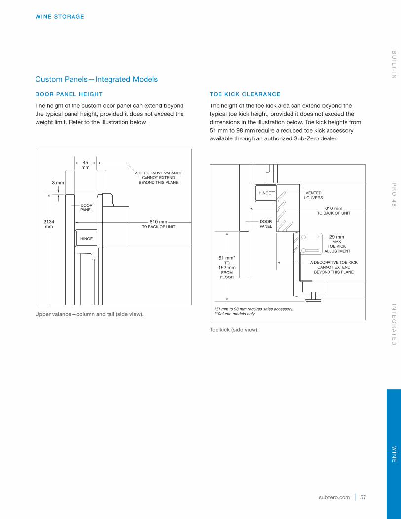
DOOR PANEL HEIGHT
The height of the custom door panel can extend beyond the typical panel height, provided it does not exceed the weight limit. Refer to the illustration below.
45mm
A DECORATIVE VALANCECANNOT EXTEND
BEYOND THIS PLANE
DOORPANEL
HINGE
610 mmTO BACK OF UNIT
2134mm
3 mm
Upper valance—column and tall (side view).
TOE KICK CLEARANCE
The height of the toe kick area can extend beyond the typical toe kick height, provided it does not exceed the dimensions in the illustration below. Toe kick heights from 51 mm to 98 mm require a reduced toe kick accessory available through an authorized Sub-Zero dealer.
610 mmTO BACK OF UNIT
VENTEDLOUVERS
HINGE**
DOORPANEL
29 mmMAX
TOE KICK ADJUSTMENT
A DECORATIVE TOE KICKCANNOT EXTEND
BEYOND THIS PLANE
51 mm*TO
152 mmFROMFLOOR
*51 mm to 98 mm requires sales accessory.**Column models only.
Toe kick (side view).
BU
ILT
-IN
PR
O 4
8IN
TE
GR
AT
ED
WIN
E

58 | English
WINE STORAGE
Custom Panels—ICBWS-30 | ICBBW-30
OVERLAY PANELS
Overlay panels are typically created by combining a 19 mm custom panel, a 3 mm spacer panel and a 6 mm backer panel. Refer to the illustrations below.
PANEL REQUIREMENTS
PANEL WEIGHT MAX
Door 34 kgGrille 6 kg
PANEL THICKNESS MIN
Overlay 16 mm
3 mm
CUSTOM PANEL
SPACER PANEL
BACKER PANEL
TRIM
8 mm min
DOOR FRAME GLASS
6 mm3mm
CUSTOMPANEL
SPACERPANEL
BACKERPANEL
19mm
TYPICAL
Panel assembly cross section (overlay).
Panel assembly rear view.
OVERLAY PANEL DIMENSIONS
H
H
W
A A
A
A
ICBWS-30, ICBBW-30
OVERLAY PANELS
DOOR W H
Overlay Panel 762 mm 1772 mmSpacer Panel 740 mm 1751 mmBacker Panel 756 mm 1767 mm
STILES | RAILS A
Minimum 83 mm
GRILLE W H
Overlay Panel 762 mm 235 mm*Spacer Panel 740 mm 211 mmBacker Panel 756 mm 227 mm
*Panel height may be increased by 11 mm to hide upper main frame.
Grille panel dimensions are for standard 2134 mm overall unit height. For 2108 mm height, subtract 25 mm from grille panel height dimensions and for 2235 mm height, add 102 mm. A specific panel grille must be ordered for a 2108 mm or 2235 mm overall unit height.
WIN
EIN
TE
GR
AT
ED
PR
O 4
8B
UIL
T-
IN

subzero.com | 59
WINE STORAGE
Custom Panels—ICBWS-30 | ICBBW-30
FLUSH INSET PANELS
The flush inset application is an overlay model with flush inset panels. It is not a separate model.
The flush inset design allows custom panels to be installed flush with adjacent cabinets. Similar to overlay, flush inset panels are typically created by combining a 19 mm custom panel, a 3 mm spacer panel and a 6 mm backer panel. Refer to the illustrations for overlay panels on the previous page.
For flush inset panels thicker than 19 mm, a 90° door stop may be required to prevent interference with adjacent cabi-nets. Refer to the full-scale template on page 68.
PANEL REQUIREMENTS
PANEL WEIGHT MAX
Door 34 kgGrille 6 kg
PANEL THICKNESS MIN
Flush Inset 16 mm
FLUSH INSET PANEL DIMENSIONS
H
H
W
A A
A
A
ICBWS-30, ICBBW-30
FLUSH INSET PANELS
DOOR W H
Flush Inset Panel 787 mm 1772 mmSpacer Panel 740 mm 1751 mmBacker Panel 756 mm 1767 mm
STILES | RAILS A
Minimum 95 mm
GRILLE W H
Flush Inset Panel 787 mm 235 mmSpacer Panel 740 mm 211 mmBacker Panel 756 mm 227 mm
Grille panel dimensions are for standard 2134 mm overall unit height. For 2108 mm height, subtract 25 mm from grille panel height dimensions and for 2235 mm height, add 102 mm. A specific panel grille must be ordered for a 2108 mm or 2235 mm overall unit height.
BU
ILT
-IN
PR
O 4
8IN
TE
GR
AT
ED
WIN
E

60 | English
WINE STORAGE
Custom Panels—ICBWS-30 | ICBBW-30
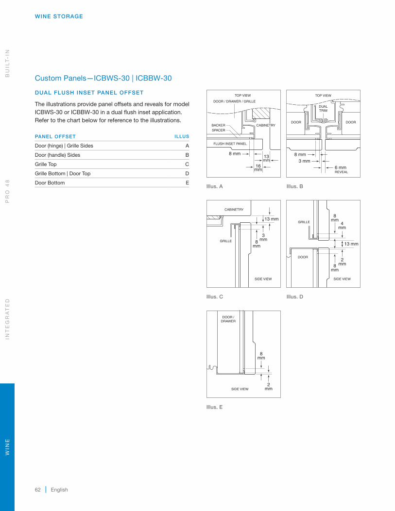
FLUSH INSET PANEL OFFSET
The illustrations provide panel offsets and reveals for model ICBWS-30 or ICBBW-30 in a flush inset application. Refer to the chart below for reference to the illustrations.
PANEL OFFSET ILLUS
Door | Grille Sides A
Grille Top B
Grille Bottom | Door Top C
Door Bottom D
16mm
16 mm
8 mm13mm
4mm
8mm
8mm
2mm
DOOR
DRAWER
8mm
2mm
DOOR /DRAWER
13 mm
2mm
8mm
8mm
4mm
GRILLE
DOOR
6 mmREVEAL
8 mm3 mm
FLUSH INSET PANEL
SPACER
BACKERDOOR DOOR
DOOR / DRAWER / GRILLE
13 mm
8mm
3mm
CABINETRY
GRILLE
TOP VIEWTOP VIEW
SIDE VIEW SIDE VIEW
SIDE VIEW SIDE VIEW
CABINETRY
16mm
16 mm
8 mm13mm
4mm
8mm
8mm
2mm
DOOR
DRAWER
8mm
2mm
DOOR /DRAWER
13 mm
2mm
8mm
8mm
4mm
GRILLE
DOOR
6 mmREVEAL
8 mm3 mm
FLUSH INSET PANEL
SPACER
BACKERDOOR DOOR
DOOR / DRAWER / GRILLE
13 mm
8mm
3mm
CABINETRY
GRILLE
TOP VIEWTOP VIEW
SIDE VIEW SIDE VIEW
SIDE VIEW SIDE VIEW
CABINETRY
Illus. A
Illus. B
16mm
16 mm
8 mm13mm
4mm
8mm
8mm
2mm
DOOR
DRAWER
8mm
2mm
DOOR /DRAWER
13 mm
2mm
8mm
8mm
4mm
GRILLE
DOOR
6 mmREVEAL
8 mm3 mm
FLUSH INSET PANEL
SPACER
BACKERDOOR DOOR
DOOR / DRAWER / GRILLE
13 mm
8mm
3mm
CABINETRY
GRILLE
TOP VIEWTOP VIEW
SIDE VIEW SIDE VIEW
SIDE VIEW SIDE VIEW
CABINETRY
16mm
16 mm
8 mm13mm
4mm
8mm
8mm
2mm
DOOR
DRAWER
8mm
2mm
DOOR /DRAWER
13 mm
2mm
8mm
8mm
4mm
GRILLE
DOOR
6 mmREVEAL
8 mm3 mm
FLUSH INSET PANEL
SPACER
BACKERDOOR DOOR
DOOR / DRAWER / GRILLE
13 mm
8mm
3mm
CABINETRY
GRILLE
TOP VIEWTOP VIEW
SIDE VIEW SIDE VIEW
SIDE VIEW SIDE VIEW
CABINETRY
Illus. C
Illus. D
WIN
EIN
TE
GR
AT
ED
PR
O 4
8B
UIL
T-
IN
subzero.com | 61
WINE STORAGE
DUAL FLUSH INSET PANEL DIMENSIONS
H
H
W
A A
A
A
ICBWS-30, ICBBW-30
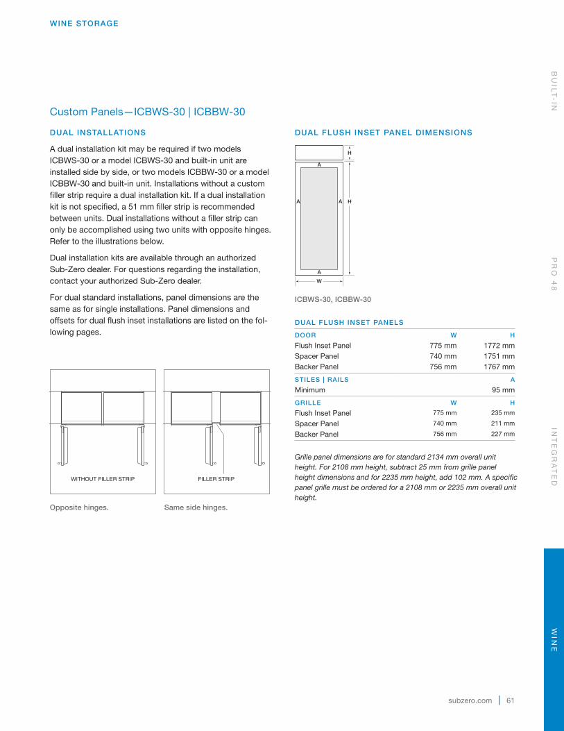
DUAL FLUSH INSET PANELS
DOOR W H
Flush Inset Panel 775 mm 1772 mmSpacer Panel 740 mm 1751 mmBacker Panel 756 mm 1767 mm
STILES | RAILS A
Minimum 95 mm
GRILLE W H
Flush Inset Panel 775 mm 235 mm
Spacer Panel 740 mm 211 mm
Backer Panel 756 mm 227 mm
Grille panel dimensions are for standard 2134 mm overall unit height. For 2108 mm height, subtract 25 mm from grille panel height dimensions and for 2235 mm height, add 102 mm. A specific panel grille must be ordered for a 2108 mm or 2235 mm overall unit height.
Custom Panels—ICBWS-30 | ICBBW-30
DUAL INSTALLATIONS
A dual installation kit may be required if two models ICBWS-30 or a model ICBWS-30 and built-in unit are installed side by side, or two models ICBBW-30 or a model ICBBW-30 and built-in unit. Installations without a custom filler strip require a dual installation kit. If a dual installation kit is not specified, a 51 mm filler strip is recommended between units. Dual installations without a filler strip can only be accomplished using two units with opposite hinges. Refer to the illustrations below.
Dual installation kits are available through an authorized Sub-Zero dealer. For questions regarding the installation, contact your authorized Sub-Zero dealer.
For dual standard installations, panel dimensions are the same as for single installations. Panel dimensions and offsets for dual flush inset installations are listed on the fol-lowing pages.
WITHOUT FILLER STRIP FILLER STRIP
Opposite hinges.
Same side hinges.
BU
ILT
-IN
PR
O 4
8IN
TE
GR
AT
ED
WIN
E
62 | English
WINE STORAGE
Custom Panels—ICBWS-30 | ICBBW-30
DUAL FLUSH INSET PANEL OFFSET
The illustrations provide panel offsets and reveals for model ICBWS-30 or ICBBW-30 in a dual flush inset application. Refer to the chart below for reference to the illustrations.
PANEL OFFSET ILLUS
Door (hinge) | Grille Sides A
Door (handle) Sides B
Grille Top C
Grille Bottom | Door Top D
Door Bottom E
16mm
16 mm
8 mm13mm
4mm
8mm
8mm
2mm
DOOR
DRAWER
8mm
2mm
DOOR /DRAWER
13 mm
2mm
8mm
8mm
4mm
GRILLE
DOOR
6 mmREVEAL
8 mm3 mm
FLUSH INSET PANEL
SPACER
BACKERDOOR DOOR
DOOR / DRAWER / GRILLE
13 mm
8mm
3mm
CABINETRY
GRILLE
TOP VIEWTOP VIEW
SIDE VIEW SIDE VIEW
SIDE VIEW SIDE VIEW
CABINETRY
DUALTRIM
6 mmREVEAL
8 mm3 mm
DOOR DOOR
TOP VIEW
Illus. A
Illus. B
16mm
16 mm
8 mm13mm
4mm
8mm
8mm
2mm
DOOR
DRAWER
8mm
2mm
DOOR /DRAWER
13 mm
2mm
8mm
8mm
4mm
GRILLE
DOOR
6 mmREVEAL
8 mm3 mm
FLUSH INSET PANEL
SPACER
BACKERDOOR DOOR
DOOR / DRAWER / GRILLE
13 mm
8mm
3mm
CABINETRY
GRILLE
TOP VIEWTOP VIEW
SIDE VIEW SIDE VIEW
SIDE VIEW SIDE VIEW
CABINETRY
16mm
16 mm
8 mm13mm
4mm
8mm
8mm
2mm
DOOR
DRAWER
8mm
2mm
DOOR /DRAWER
13 mm
2mm
8mm
8mm
4mm
GRILLE
DOOR
6 mmREVEAL
8 mm3 mm
FLUSH INSET PANEL
SPACER
BACKERDOOR DOOR
DOOR / DRAWER / GRILLE
13 mm
8mm
3mm
CABINETRY
GRILLE
TOP VIEWTOP VIEW
SIDE VIEW SIDE VIEW
SIDE VIEW SIDE VIEW
CABINETRY
Illus. C
Illus. D
16mm
16 mm
8 mm13mm
4mm
8mm
8mm
2mm
DOOR
DRAWER
8mm
2mm
DOOR /DRAWER
13 mm
2mm
8mm
8mm
4mm
GRILLE
DOOR
6 mmREVEAL
8 mm3 mm
FLUSH INSET PANEL
SPACER
BACKERDOOR DOOR
DOOR / DRAWER / GRILLE
13 mm
8mm
3mm
CABINETRY
GRILLE
TOP VIEWTOP VIEW
SIDE VIEW SIDE VIEW
SIDE VIEW SIDE VIEW
CABINETRY
Illus. E
WIN
EIN
TE
GR
AT
ED
PR
O 4
8B
UIL
T-
IN
subzero.com | 63
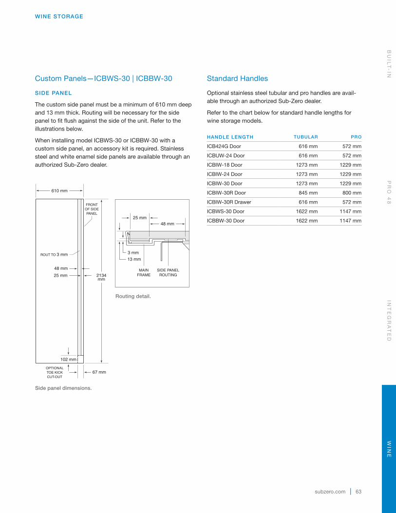
WINE STORAGE
Custom Panels—ICBWS-30 | ICBBW-30
SIDE PANEL
The custom side panel must be a minimum of 610 mm deep and 13 mm thick. Routing will be necessary for the side panel to fit flush against the side of the unit. Refer to the illustrations below.
When installing model ICBWS-30 or ICBBW-30 with a custom side panel, an accessory kit is required. Stainless steel and white enamel side panels are available through an authorized Sub-Zero dealer.
2134mm
610 mm
OPTIONALTOE KICKCUT-OUT
102 mm
48 mm
25 mm
ROUT TO 3 mm
FRONTOF SIDEPANEL
67 mm
MAINFRAME
SIDE PANELROUTING
25 mm48 mm
3 mm
13 mm
Side panel dimensions.
Routing detail.
Standard Handles
Optional stainless steel tubular and pro handles are avail-able through an authorized Sub-Zero dealer.
Refer to the chart below for standard handle lengths for wine storage models.
HANDLE LENGTH TUBULAR PRO
ICB424G Door 616 mm 572 mm
ICBUW-24 Door 616 mm 572 mm
ICBIW-18 Door 1273 mm 1229 mm
ICBIW-24 Door 1273 mm 1229 mm
ICBIW-30 Door 1273 mm 1229 mm
ICBIW-30R Door 845 mm 800 mm
ICBIW-30R Drawer 616 mm 572 mm
ICBWS-30 Door 1622 mm 1147 mm
ICBBW-30 Door 1622 mm 1147 mm
BU
ILT
-IN
PR
O 4
8IN
TE
GR
AT
ED
WIN
E
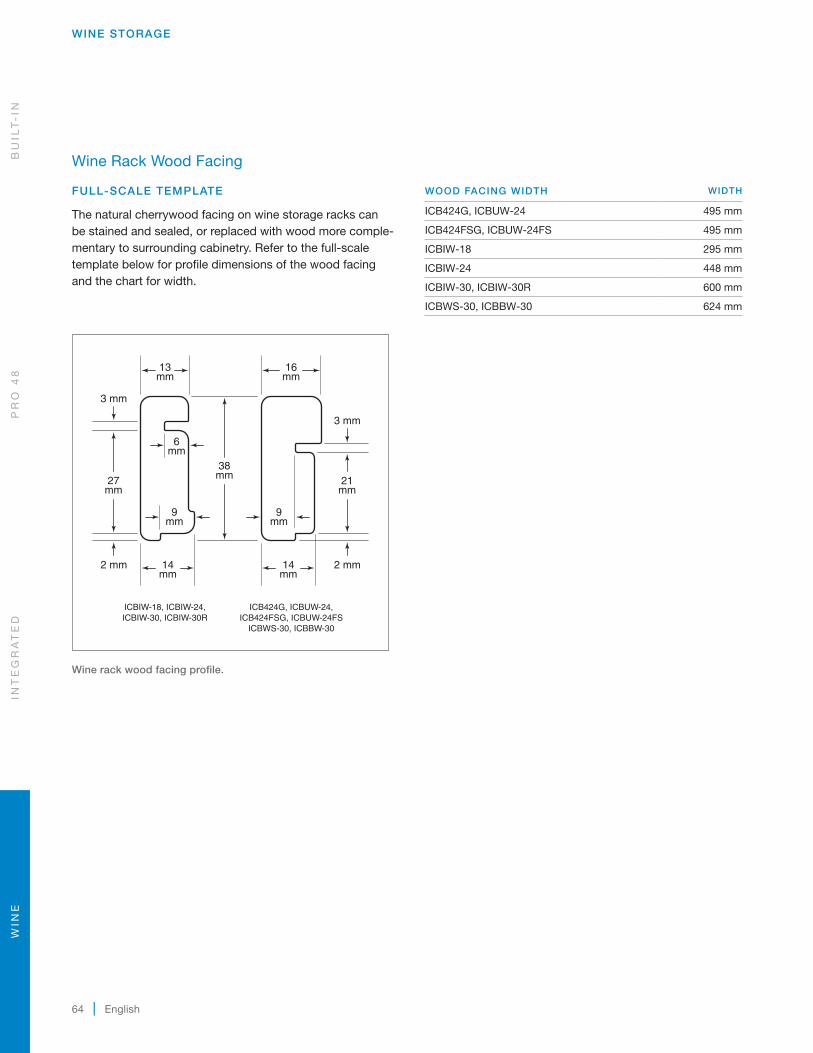
64 | English
Wine Rack Wood Facing
FULL-SCALE TEMPLATE
The natural cherrywood facing on wine storage racks can be stained and sealed, or replaced with wood more comple-mentary to surrounding cabinetry. Refer to the full-scale template below for profile dimensions of the wood facing and the chart for width.
WINE STORAGE
38mm 21
mm
3 mm
2 mm
9mm
9mm
13mm
27mm
6mm
16mm
14mm
2 mm 14mm
3 mm
ICB424G, ICBUW-24,ICB424FSG, ICBUW-24FS
ICBWS-30, ICBBW-30
ICBIW-18, ICBIW-24,ICBIW-30, ICBIW-30R
Wine rack wood facing profile.
WOOD FACING WIDTH WIDTH
ICB424G, ICBUW-24 495 mm
ICB424FSG, ICBUW-24FS 495 mm
ICBIW-18 295 mm
ICBIW-24 448 mm
ICBIW-30, ICBIW-30R 600 mm
ICBWS-30, ICBBW-30 624 mm
WIN
EIN
TE
GR
AT
ED
PR
O 4
8B
UIL
T-
IN

subzero.com | 65
WINE STORAGE
DOOR CLOSED
UNDERCOUNTERUNIT
ADJACENTCABINETRY
19 mm DOOR PANEL
13mm
3mm
6 mm
HINGE AT 145°OPENING
(DOOR OPENS PAST 145°)
25 mm0
SCALE
145° door opening (top view).
Door Clearance—ICB424G | ICBUW-24
FULL-SCALE TEMPLATE
To allow for a 145° door opening, the unit should extend a minimum of 6 mm beyond the front surface of adjacent cabinetry. The unit can be installed flush, however, there is potential for interference with the panel if the door is opened past 90°.
BU
ILT
-IN
PR
O 4
8IN
TE
GR
AT
ED
WIN
E

66 | English
Overlay | Flush Inset Panels—ICBWS-30 | ICBBW-30
FULL-SCALE TEMPLATE
Overlay and flush inset panels must be a minimum of 16 mm thick to support mounting the handle. Panel thickness does not include backer and spacer panel. Mount handle close to the opening edge of the door.
Overlay and flush inset panel thickness.
6 mm BACKER PANEL
DOOR
DEPTH OF TUBULARAND PRO HANDLES
25mm
76mm
32 mm PANEL
25 mm PANEL
19 mm PANEL
51mm
3 mm SPACER PANEL
WINE STORAGE
WIN
EIN
TE
GR
AT
ED
PR
O 4
8B
UIL
T-
IN
Sub-Zero, Sub-Zero & Design, Sub-Zero & Snowflake Design, Dual Refrigeration, The Living Kitchen, Great American Kitchens The Fine Art of Kitchen Design, Wolf, Wolf & Design, Wolf Gourmet, W & Design, red colored knobs, Cove, and Cove & Design, are registered trademarks and service marks of Sub-Zero Group, Inc. and its subsidiaries. All other trademarks are property of their respective owners in the United States and other countries.
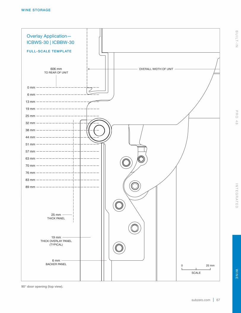
subzero.com | 67
WINE STORAGE
606 mmTO REAR OF UNIT
OVERALL WIDTH OF UNIT
32 mm
38 mm
44 mm
0 mm
25 mm
51 mm
57 mm
63 mm
70 mm
76 mm
83 mm
89 mm
6 mm
13 mm
19 mm
19 mmTHICK OVERLAY PANEL
(TYPICAL)
6 mmBACKER PANEL
25 mmTHICK PANEL
25 mm0
SCALE
90° door opening (top view).
Overlay Application—ICBWS-30 | ICBBW-30
FULL-SCALE TEMPLATE
BU
ILT
-IN
PR
O 4
8IN
TE
GR
AT
ED
WIN
E
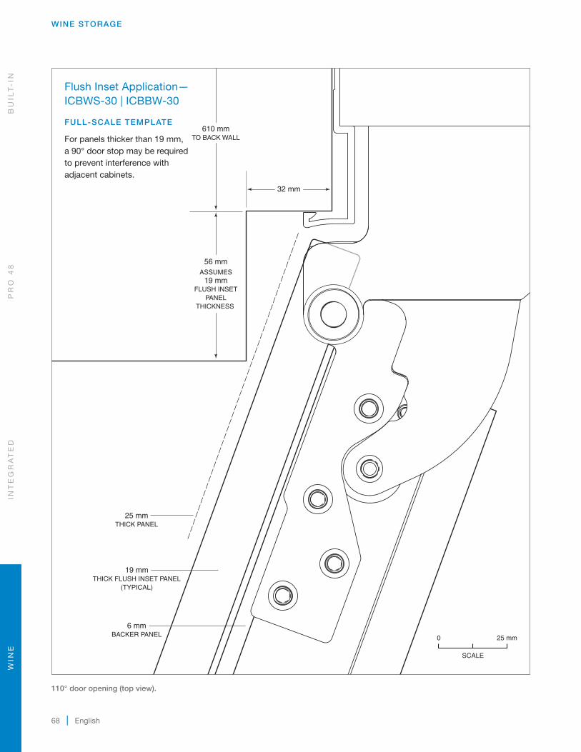
68 | English
WINE STORAGE
32 mm
ASSUMES19 mm
FLUSH INSETPANEL
THICKNESS
56 mm
610 mmTO BACK WALL
19 mmTHICK FLUSH INSET PANEL
(TYPICAL)
6 mmBACKER PANEL
25 mmTHICK PANEL
25 mm0
SCALE
110° door opening (top view).
Flush Inset Application—ICBWS-30 | ICBBW-30
FULL-SCALE TEMPLATE
For panels thicker than 19 mm, a 90° door stop may be required to prevent interference with adjacent cabinets.
WIN
EIN
TE
GR
AT
ED
PR
O 4
8B
UIL
T-
IN

subzero.com | 69
WINE STORAGE
32 mm
FILLER STRIP
APPROX PROFILE OFSTAINLESS STEEL WRAPPED
DOOR AND HANDLE
DOOROPEN 110°
DOORCLOSED
Dual standard installation (top view).
Dual Standard Installation— ICBWS-30 | ICBBW-30
FULL-SCALE TEMPLATE
Typical overlay or stainless steel dual instal-lation with filler strip at maximum 110° door opening. Panel thickness may require a 90° door stop.
25 mm0
SCALE
BU
ILT
-IN
PR
O 4
8IN
TE
GR
AT
ED
WIN
E

70 | English
WINE STORAGE
38 mm
13 mm
FILLER STRIP
PROFILE OF 19 mm FLUSH INSET PANELAND TUBULAR HANDLE
DOORCLOSED
DOOROPEN 110°
Dual flush inset installation (top view).
Dual Flush Inset Installation— ICBWS-30 | ICBBW-30
FULL-SCALE TEMPLATE
Typical flush inset dual installation with filler strip at maximum 110° door opening. Panel thickness may require a 90° door stop.
25 mm0
SCALE
WIN
EIN
TE
GR
AT
ED
PR
O 4
8B
UIL
T-
IN

Sub-Zero, Sub-Zero & Design, Sub-Zero & Snowflake Design, Dual Refrigeration, The Living Kitchen, Great American Kitchens The Fine Art of Kitchen Design, Wolf, Wolf & Design, Wolf Gourmet, W & Design, red colored knobs, Cove, and Cove & Design, are registered trademarks and service marks of Sub-Zero Group, Inc. and its subsidiaries. All other trademarks are property of their respective owners in the United States and other countries.
subzero.com | 71

Sub-Zero International Limited Warranty
FOR RESIDENTIAL USE
FULL TWO YEAR WARRANTY*
For two years from the date of original installation, this Sub-Zero product warranty covers all parts and labor to repair or replace, under normal residential use, any part of the product that proves to be defec-tive in materials or workmanship. All service provided by Sub-Zero under the above warranty must be performed by Sub-Zero factory certified service, unless otherwise specified by Sub-Zero, Inc. Service will be provided during normal business hours.
FULL FIVE YEAR SEALED SYSTEM WARRANTY
For five years from the date of original installation, this Sub-Zero product warranty covers all parts and labor to repair or replace, under normal residential use, these parts that prove to be defective in materials or workmanship: compressor, condenser, evaporator, drier and all connecting tubing. All service provided by Sub-Zero under the above warranty must be performed by Sub-Zero factory certified service, unless otherwise specified by Sub-Zero, Inc. Service will be provided during normal business hours.
For more information regarding your Sub-Zero product warranty, contact your authorized Sub-Zero dealer. Warranties must comply to all country, state, city, local and or ordinance.
*Stainless steel (doors, panels, handles, product frames and interior surfaces) are covered by a limited 60-day parts and labor warranty for cosmetic defects.
*Replacement water filters and air purification cartridges are not covered by the product warranty.

Sub-Zero International Outdoor Limited Warranty*
FOR RESIDENTIAL USE
FULL ONE YEAR WARRANTY**
For one year from the date of original installation, this Sub-Zero product warranty covers all parts and labor to repair or replace, under normal residential use, any part of the product that proves to be defective in materials or workmanship. All service provided by Sub-Zero under the above warranty must be performed by Sub-Zero factory certified service, unless otherwise specified by Sub-Zero, Inc. Service will be provided during normal business hours.
FULL FIVE YEAR SEALED SYSTEM WARRANTY
For five years from the date of original installation, this Sub-Zero product warranty covers all parts and labor to repair or replace, under normal residential use, these parts that prove to be defective in materials or workmanship: compressor, condenser, evaporator, drier and all connecting tubing. All service provided by Sub-Zero under the above warranty must be performed by Sub-Zero factory certified service, unless otherwise specified by Sub-Zero, Inc. Service will be provided during normal business hours.
TERMS APPLICABLE TO EACH WARRANTY
The warranty applies only to products installed for normal residential use. This warranty does not cover any parts or labor to correct any defect caused by negligence, accident or improper use, maintenance, installation, service or repair.
For more information regarding your Sub-Zero product warranty, contact your dealer. Warranties must comply to all country, state, city, local and or ordinance.
*Product must be approved for outdoor use, designated by model and serial number.
**Stainless steel (doors, panels, handles, product frames and interior surfaces) are covered by a limited 60-day parts and labor warranty for cosmetic defects.
**Replacement water filters and air purification cartridges are not covered by the product warranty.

SUBZERO.COM