design guide vlt brook crompton motor fcm 300
TRANSCRIPT

MAKING MODERN LIVING POSSIBLE
Design GuideVLT® Brook Crompton Motor FCM 300
www.danfoss.com/drives


Contents
1 Introduction 4
1.1.1 Software Version 4
1.1.5 Safety Regulations 5
1.1.6 Warning against Unintended Start 5
1.3.1 Integration of Frequency Converter and Motor 6
1.4.1 Ordering Form 7
1.4.2 Product Range 8
1.4.3 Ordering 9
1.4.4 PC Software Tools 9
1.4.5 Ordering info for Frames and Flanges 10
1.4.6 Ordering Info for Inverter Box Position and Drain Hole Position 10
2 Installation 11
2.1.1 FCM 305-375 for 3 Phases, 380-480 V 11
2.1.2 General Technical Data 12
2.1.3 Tightening Torques 15
2.1.4 Maximum Cable Cross Section 15
2.1.5 Screw Sizes 16
2.1.6 Protection 16
2.2 Description of the Motor 17
2.2.1 Handling the FC Motor 18
2.2.2 Bearings 18
2.2.3 Output shafts 19
2.2.4 Dimensions 19
2.2.5 Installation of the FC Motor 21
2.2.6 Alignment 22
2.2.7 Bolt Torques 22
2.2.8 Maintenance 22
2.2.9 FCM 300 Thermal Protection 23
2.3.1 Service Plug Kit (175N2546) 23
2.3.2 Plug Kit (175N2545) 25
2.3.3 Remote Mounting Kit (175N0160) 25
2.3.5 Potentiometer Option (177N0011) 26
2.3.6 Local Operation Pad (LOP) (175N0128) IP65 26
3 Programming 28
3.1.1 Control Panel (175NO131) 28
3.1.2 LCP Installation 28
3.1.3 LCP Functions 28
3.1.4 Display 28
Contents VLT® DriveMotor FCM Series
MG03BA02 - VLT® is a registered Danfoss trademark 1

3.1.5 LEDs 29
3.1.6 Control Keys 29
3.1.7 Control Key Functions 29
3.1.8 Display Read-out State 30
3.1.9 Display Mode 30
3.1.10 Display Mode - Selection of Read-out State 30
3.1.11 Quick Menu Mode Versus Menu Mode 31
3.1.12 Quick Setup via Quick Menu 32
3.1.13 Parameter Selection 32
3.1.14 Menu Mode 32
3.1.15 Parameter Groups 32
3.1.16 Changing Data 33
3.1.17 Changing a Text Value 33
3.1.18 Infinitely Variable Change of Numeric Data Value 33
3.1.19 Menu Structure 34
3.1.20 Parameter Group 0-** Operation/Display 36
3.2.1 Parameter Group 1-** Load/Motor 40
3.6.1 Serial Bus 60
3.6.2 Telegram Communication 60
3.6.3 Telegram Build-up 61
3.6.4 Databytes 61
3.6.5 Control Word According to Fieldbus Profile Standard 63
3.7.1 Parameter Group 5-** Serial Communication 69
3.8.1 Parameter Group 6-** Technical Functions 74
4 All about FCM 300 77
4.1.1 Galvanic Isolation (PELV) 77
4.1.2 Earth Leakage Current 77
4.1.3 Extreme Running Conditions 78
4.1.4 Acoustic Noise 78
4.1.5 Balance 78
4.1.6 Thermal Protection and Derating 78
4.1.7 Derating for Ambient Temperature 79
4.1.8 Derating for Air Pressure 79
4.1.9 Derating for Running at Low Speed 79
4.1.10 Derating for High Switching Frequency 79
4.1.11 Vibration and Shock 80
4.1.12 Air Humidity 80
4.1.13 UL Standard 80
4.1.14 Efficiency 80
4.1.15 Mains Supply Interference/Harmonics 81
Contents VLT® DriveMotor FCM Series
2 MG03BA02 - VLT® is a registered Danfoss trademark

4.1.16 Power Factor 82
4.1.17 What is CE Labelling? 82
4.1.18 The Machinery Directive (98/37/EEC) 82
4.1.19 The Low-voltage Directive (73/23/EEC) 82
4.1.20 The EMC Directive (89/336/EEC) 82
4.1.21 What is Covered? 82
4.1.22 Danfoss FCM 300 Series Motor and CE Labelling 83
4.1.23 Compliance with EMC Directive 89/336/EEC 83
4.1.24 EMC Standards 83
4.1.25 Aggressive Environments 84
4.2.1 List of Warnings and Alarms 84
4.2.2 What if the Motor does not Start? 85
4.2.3 Warnings 86
4.2.4 Warning Word, Extended Status Word and Alarm Word 88
4.3 List of Parameters 89
Index 95
Contents VLT® DriveMotor FCM Series
MG03BA02 - VLT® is a registered Danfoss trademark 3
1 Introduction
1.1 Safety
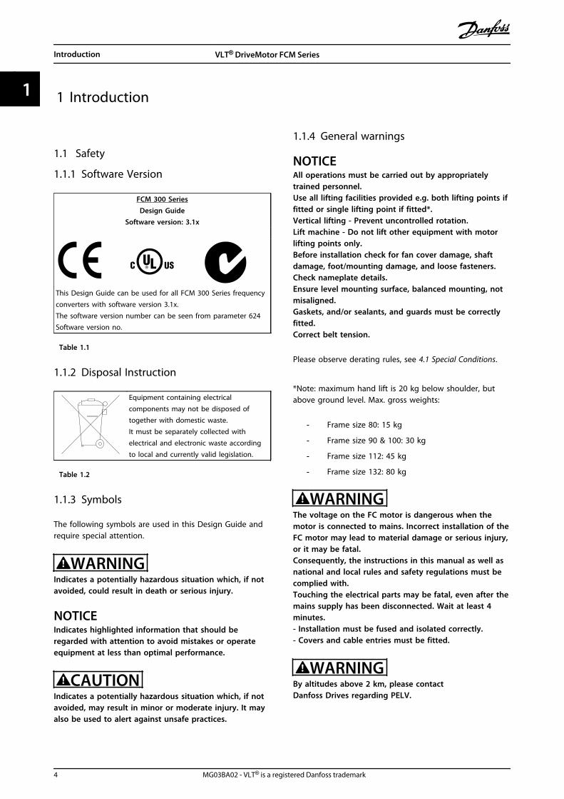
1.1.1 Software Version
FCM 300 SeriesDesign Guide
Software version: 3.1x
This Design Guide can be used for all FCM 300 Series frequencyconverters with software version 3.1x.The software version number can be seen from parameter 624Software version no.
Table 1.1
1.1.2 Disposal Instruction
Equipment containing electricalcomponents may not be disposed oftogether with domestic waste.It must be separately collected withelectrical and electronic waste accordingto local and currently valid legislation.
Table 1.2
1.1.3 Symbols
The following symbols are used in this Design Guide andrequire special attention.
WARNINGIndicates a potentially hazardous situation which, if notavoided, could result in death or serious injury.
NOTICEIndicates highlighted information that should beregarded with attention to avoid mistakes or operateequipment at less than optimal performance.
CAUTIONIndicates a potentially hazardous situation which, if notavoided, may result in minor or moderate injury. It mayalso be used to alert against unsafe practices.
1.1.4 General warnings
NOTICEAll operations must be carried out by appropriatelytrained personnel.Use all lifting facilities provided e.g. both lifting points iffitted or single lifting point if fitted*.Vertical lifting - Prevent uncontrolled rotation.Lift machine - Do not lift other equipment with motorlifting points only.Before installation check for fan cover damage, shaftdamage, foot/mounting damage, and loose fasteners.Check nameplate details.Ensure level mounting surface, balanced mounting, notmisaligned.Gaskets, and/or sealants, and guards must be correctlyfitted.Correct belt tension.
Please observe derating rules, see 4.1 Special Conditions.
*Note: maximum hand lift is 20 kg below shoulder, butabove ground level. Max. gross weights:
- Frame size 80: 15 kg
- Frame size 90 & 100: 30 kg
- Frame size 112: 45 kg
- Frame size 132: 80 kg
WARNINGThe voltage on the FC motor is dangerous when themotor is connected to mains. Incorrect installation of theFC motor may lead to material damage or serious injury,or it may be fatal.Consequently, the instructions in this manual as well asnational and local rules and safety regulations must becomplied with.Touching the electrical parts may be fatal, even after themains supply has been disconnected. Wait at least 4minutes.- Installation must be fused and isolated correctly.- Covers and cable entries must be fitted.
WARNINGBy altitudes above 2 km, please contactDanfoss Drives regarding PELV.
Introduction VLT® DriveMotor FCM Series
4 MG03BA02 - VLT® is a registered Danfoss trademark
11

NOTICEIt is the user's or certified electrician's responsibility toensure correct earthing and protection in accordancewith applicable national and local requirements andstandards.
1.1.5 Safety Regulations
• The VLT DriveMotor (FC motor) must be discon-nected from mains if repair work is to be carriedout.Check that the mains supply has been discon-nected and that the necessary time has passed (4minutes).
• Correct protective earthing of the equipmentmust be established, the user must be protectedagainst supply voltage, and the motor must beprotected against overload in accordance withapplicable national and local regulations.Use of RCD's (ELCB relays) is described in 4.1.2 Earth Leakage Current .
• The earth leakage currents are higher than 3.5mA. This means that the FC motor requires afixed, permanent installation as well as reinforcedprotective earthing.
1.1.6 Warning against Unintended Start
• The motor can be brought to a stop by means ofdigital commands, bus commands, or references,while the frequency converter is connected tomains.
If personal safety considerations make itnecessary to ensure that no unintended startoccurs, these stop functions are not sufficient.
• While parameters are being changed, the motormay start.
• A motor that has been stopped may start if faultsoccur in the electronics of the FC motor, or if atemporary overload or a fault in the mains supplyceases.
1.2 Introduction
Specific technical publications on the FCM 300 series:
Design Guide: Gives all required information for designpurposes, and gives a good insight intothe product concept, product range,technical data, control, programming, etc.
Quick Setup: Helps the users to quickly get their FCM300 Series motor unit installed andrunning.The Quick Setup is always delivered withthe unit.
Table 1.3
For further information on the FCM 300 Series, contact thelocal Danfoss supplier.
175N
A16
1.10Promotion All
users
X = version numberYY = language
Misc.
Quick SetupMG.03.FX.YY
DesignGuide
MG03BXYY
PROFIBUS-Manual
MG.03.EX.YY
BrochureMB.03.CX.YY
ArticlesMZ.03.AX.YY
MCT 10 SetupSoftware Manual
MG10RXYY
Data sheetMD.03.AX.YY
Illustration 1.1 Available literature for FCM 300 Series
Introduction VLT® DriveMotor FCM Series
MG03BA02 - VLT® is a registered Danfoss trademark 5
1 1

1.3 Product Concept
1.3.1 Integration of Frequency Converterand Motor
The Danfoss VLT frequency converter integrated onto theasynchronous motor gives infinite speed control in oneunit.
The VLT DriveMotor FCM 300 Series is a very compactalternative to the ordinary solution with VLT frequencyconverter and motor as separate units. The frequencyconverter is attached instead of the motor terminal box,and it is no higher than the standard terminal box, norwider or longer than the motor (see 2.2.4 Dimensions ).
Installation is extremely easy. Panel space is not a problem.There is no need for special details on wiring to meet theEMC directive, since motor cables are not necessary. Theonly connections are mains and control connections.
Factory-set adaption between frequency converter andmotor gives precise and energy efficient control inaddition to eliminating pre-setting on site.
The FC motor can be used in stand alone Systems withtraditional control signals, such as start/stop signals, speedreferences and closed loop process control or in multipledrive Systems with control signals distributed by a fieldbus.
Combination of fieldbus and traditional control signals andclosed loop PID control is possible.
Proc.
Fieldbus
DanfossMCT 10 setup Software
PLC
Proc.
175N
A00
9.13
Illustration 1.2 Control Structures
Introduction VLT® DriveMotor FCM Series
6 MG03BA02 - VLT® is a registered Danfoss trademark
11
1.4 Selection of FC motor, FCM 300
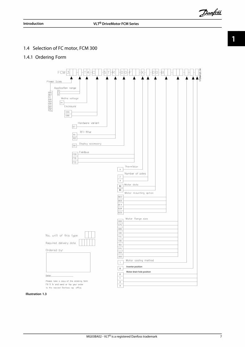
1.4.1 Ordering Form
175N
A12
1.14
B2
BC
Inverter position
Motor drain hole position
D
0
1
2
3
Illustration 1.3
Introduction VLT® DriveMotor FCM Series
MG03BA02 - VLT® is a registered Danfoss trademark 7
1 1

1.4.2 Product Range
VLT DriveMotor FCM 300 Series, 2/4 poled motors
Type Motor output Mains supply
FCM 305 0.55 kW
3 phase 380-480 V
FCM 307 0.75 kW
FCM 311 1.1 kW
FCM 315 1.5 kW
FCM 322 2.2 kW
FCM 330 3.0 kW
FCM 340 4.0 kW
FCM 355 5.5 kW
FCM 375 7.5 kW
Table 1.4 Power Size
Each type in the product range is available in differentversions:
Inverter versions
Power size:(See Table 1.4)
Application
• P: Process
• S: Sensorless (special pump OEM)
Mains voltage:
• T4: 380-480 V three phase supply
Enclosure
• C55: IP55
• C66: IP66
Hardware variant:
• ST: Standard
RFI filter
• R1: Compliance with class 1A
• R2: Compliance with class 1B
Display connector
• D0: No display plug able connector
Fieldbus
• F00: No fieldbus
• F10: Profibus DPV1 3 MB
• F12: Profibus DPV1 12 MB
Motor thermistor
• X: No motor thermistor
Number of poles
• 2: 2 pole motor
• 4: 4 pole motor
Motor data
• B2: IE2 high efficiency motor
• BC: IE2 high efficiency motor/cast iron
Motor mounting option
• B03: Foot mounting
• B05: B5 flange
• B14: B14 face
• B34: Foot and B14 face
• B35: Foot and B5 flange
Motor flange code(Regarding standard flange size and available flange sizes,see 1.4.5 Ordering info for Frames and Flanges).
• 000: Foot mounting only
• 085: 85 mm
• 100: 100 mm
• 115: 115 mm
• 130: 130 mm
• 165: 165 mm
• 215: 215 mm
• 265: 265 mm
• 300: 300 mm
Motor cooling method
• 1: Shaft mounted fan
Inverter position
• D: Standard on top
Motor drain hole position(see 1.4.6 Ordering Info for Inverter Box Position and DrainHole Position)
• 0: No drain hole
• 1: Opposite inverter box both ends (drive/nondrive)
• 2: 90° inverter box right
• 3: 90° inverter box left
Introduction VLT® DriveMotor FCM Series
8 MG03BA02 - VLT® is a registered Danfoss trademark
11

1.4.3 Ordering
Take a copy of the ordering form, see 1.4.1 Ordering Form.Fill in and post or fax your order to the nearest branchoffice of the Danfoss sales organisation. On the basis ofyour order, the FCM 300 Series motor is given a type code.
The ordering form for the basic unit must always becompleted. When the type code is written, always state thecharacters of the basic string (1-34). Together with theorder confirmation the customer receives an 8-figure codenumber to be used when reordering.
Danfoss PC software for serial communication, MCT 10All FCM 300 Series units have an RS 485 port as standard,which enables them to communicate e.g. with a PC. Aprogramme entitled MCT 10 is available for this purpose(see 1.4.4 PC Software Tools ).
Ordering numbers, MCT 10Use code number 130B1000 for ordering the CDcontaining MCT 10 Set-up Software.
Accessories for the FC motorA Local Operation Pad (LOP) for local set point and start/stop is available for the FC motor. The LOP is IP 65enclosed. A Local Control Panel (LCP 2) which makes up acomplete interface for operation, programming andmonitoring of the FC motor is also available.
Ordering numbers, accessories
Local Operation Pad incl. cable (LOP) 175N0128
Local Control Panel (LCP 2) 175N0131
Remote mounting kit (LCP 2) 175N0160
Plug kit (LCP 2) 175N2545
Cable for plug kit (LCP 2) 175N0162
Cable (direct mounting) (LCP 2) 175N0165
Service plug kit (LCP 2) 175N2546
Potentiometer option 177N0011
Table 1.5
1.4.4 PC Software Tools
PC Software - MCT 10All frequency converters are equipped with a serialcommunication port. Danfoss provides a PC tool forcommunication between PC and frequency converter, VLTMotion Control Tool MCT 10 Set-up Software.
MCT 10 Set-up SoftwareMCT 10 has been designed as an easy to use interactivetool for setting parameters in our frequency converters.The MCT 10 Set-up Software will be useful for:
• Planning a communication network off-line. MCT10 contains a complete frequency converterdatabase
• Commissioning frequency converters on line
• Saving settings for all frequency converters
• Replacing a drive in a network
• Expanding an existing network
• Future developed drives will be supported
The MCT 10 Set-up Software ModulesThe following modules are included in the softwarepackage:
175N
A16
2.10
Illustration 1.4
Introduction VLT® DriveMotor FCM Series
MG03BA02 - VLT® is a registered Danfoss trademark 9
1 1

1.4.5 Ordering info for Frames and Flanges
Frame sizes and the corresponding flange sizes fordifferent mounting versions
TypeMotor frame size
Mounting versionFlange size, standard
(S) [mm]Flange size,
alternatives (A) [mm]Flange size,
alternatives (B) [mm]4 pole
FCM 305 80B5/B35 165 115/130
B14/B34 100 75/85/115/130
FCM 307 80B5/B35 165 115/130
B14/B34 100 75/85/115/130
FCM 311 90B5/B35 165 110/115/130 215
B14/B34 115 85/100/130/165
FCM 315 90B5/B35 165 110/115/130 215
B14/B34 115 85/100/130/165
FCM 322 100B5/B35 215 165
B14/B34 130 165 85/100/115
FCM 330 100B5/B35 215 165
B14/B34 130 165 85/100/115
FCM 340 112B5/B35 215 165
B14/B34 130 165 85/100/115
FCM 355 132B5/B35 265 215
B14/B34 165 215
FCM 375 132B5/B35 265 215
B14/B34 165 215
S: Available as standard shaftA: Available as an alternative with specially elongated shaft to provide standard shaft for frameB: Available as an alternative with standard shaft for frame, requiring no modification
Table 1.6
1.4.6 Ordering Info for Inverter Box Position and Drain Hole Position
Inverter box position, always top mounted.All drain holes are mounted with screw and washer, IP 66if not opened.
ISA
ISA
2 3
1
ISAISA 1
ISA
1
175N
A12
5.11
Illustration 1.5
1: Drain holes opposite inverter side, both drive end andnon drive end.2/3: Drain holes 90° to inverter, both drive end and nondrive end.
Introduction VLT® DriveMotor FCM Series
10 MG03BA02 - VLT® is a registered Danfoss trademark
11

2 Installation
2.1 Technical Data
2.1.1 FCM 305-375 for 3 Phases, 380-480 V
FCM 305 307 311 315 322 330 340 355 375Motor output[HP] 0.75 1.0 1.5 2.0 3.0 4.0 5.0 7.5 10.0[kW] 0.55 0.75 1.1 1.5 2.2 3.0 4.0 5.5 7.5Motor torque2 pole [Nm]1) 1.8 2.4 3.5 4.8 7.0 9.5 12.6 17.5 24.04 pole [Nm]2) 3.5 4.8 7.0 9.6 14.0 19.1 25.4 35.0 48.0Framesize [mm] 80 80 90 90 100 100 112 132 132DriveMotor Weight[kg]3)
11 13 17 20 26 28 37 56 61
Drive Weight [kg] 2.2 2.2 2.8 2.8 4.1 4.2 6.4 10.4 10.4Input current [A]380 V 2 p 1.5 1.8 2.3 3.4 4.5 5.0 8.0 12.0 15.0380 V 4 p 1.4 1.7 2.5 3.3 4.7 6.4 8.0 11.0 15.5480 V 2 p 1.2 1.4 1.8 2.7 3.6 4.0 6.3 9.5 11.9480 V 4 p 1.1 1.3 2.0 2.6 3.7 5.1 6.3 8.7 12.3Efficiency at nom. speed2 pole 73.4 75.3 77.5 79.0 81.3 82.7 83.8 85.1 86.24 pole 75.9 77.5 79.3 80.5 82.4 83.6 84.6 85.8 86.7Power terminals[AWG] 10 10 10 10 10 10 10 6 6[mm2] 4 4 4 4 4 4 4 10 10Gland sizes 3xM20x1.5 3xM20x1.5 3xM20x1.5 3xM20x1.5 3xM20x1.5 3xM20x1.5 3xM20x1.5 1xM25x1.5/
2xM20x1.51xM25x1.5/2xM20x1.5
Max. prefuseUL4) [A] 10 10 10 10 10 15 15 25 25IEC4) [A] 25 25 25 25 25 25 25 25 251) At 400 V 3000 r/min2) At 400 V 1500 r/min3) 2 pole motor - B34) Type gG prefuses must be used. To maintain UL/cUL, use prefuses of the type Bussmann KTS-R 500 V or Ferraz Shawmut, ATMR Class C(max. 30 A). The fuses must be placed for protection in a circuit that is capable of supplying a maximum of 100,000 amps RMS(symmetrical), 500 V maximum.
Table 2.1
Installation VLT® DriveMotor FCM Series
MG03BA02 - VLT® is a registered Danfoss trademark 11
2 2

2.1.2 General Technical Data
Mains supply, TT, TN and IT* (L1, L2, L3)Supply voltage 380-480 V units 3x380/400/415/440/460/480 V ±10%Supply frequency 50/60 HzMax. imbalance of supply voltage ±2% of rated supply voltagePower factor / cos max. 0.9/1.0 at rated loadNo. of switching operations on supply input L1, L2, L3 approx. 1 time/2 min
*) Not valid for RFI class 1B units
Torque characteristicsStarting torque/overload torque 160% for 1 minContinuous torque see above
Control card, digital/pulse inputsNumber of programmable digital inputs 4Terminal nos. X101-2, -3, -4, -5Voltage level 0-24 V DC (PNP positive logics)Voltage level, logic 0 <5 V DCVoltage level, logic 1 >10 V DCMaximum voltage on input 28 V DCInput resistance, Ri approx. 2 kΩScanning time 20 mses
Control card, pulse inputNo. of programmable pulse inputs 1Terminal nos. X101-3Max. frequency on terminal 3, open collector/push pull 24 V 8 kHz/70 kHzResolution 10 bitAccuracy (0.1-1 kHz), terminal 3 Max. error: 0.5% of full scaleAccuracy (1-12 kHz), terminal 3 Max. error: 0.1% of full scale
Control card, analogue inputsNo. of programmable analogue voltage inputs 1Terminal nos. X101-2Voltage level 0-10 V DC (scalable)Input resistance, Ri approx. 10 kΩNo. of programmable analogue current inputs 1Terminal no. X101-1Current range 0 - 20 mA (scalable)Input resistance, Ri approx. 300 ΩResolution 9 bitAccuracy on input Max. error 1% of full scaleScanning time 20 ms.
Control card, digital/pulse and analogue outputsNo. of programmable digital and analogue outputs 1Terminal nos. X101-9Voltage level at digital output/load 0 - 24 V DC/25 mACurrent at analogue output 0 - 20 mAMaximum load to frame (terminal 8) at analogue output RLOAD 500 ΩAccuracy of analogue output Max. error: 1.5% of full scaleResolution on analogue output. 8 bit
Relay outputNo. of programmable relay outputs 1Terminal number (resistive and inductive load) 1-3 (break), 1-2 (make)Max. terminal load (AC1) on 1-3, 1-2 250 V AC, 2A, 500 VA
Installation VLT® DriveMotor FCM Series
12 MG03BA02 - VLT® is a registered Danfoss trademark
22

Max. terminal load (DC1) (IEC 947) on 1-3, 1-2 25 V DC, 3A/50 V DC, 1.5 A , 75 WMin. terminal load (AC/DC) on 1-3, 1-2 control card 24 V DC, 10 mA/24 V AC, 100 mA
Rated values for up to 300,000 operations (at inductive loads the number of operations is reduced by 50%)
Control card, RS 485 serial communicationTerminal nos. X100-1, -2
Control characteristics (frequency converter)
Frequency range0-132 Hz
See 4.1 Special Conditions for frequency range for IP 66 motors at the end of this section.Resolution on output frequency 0.1%System response time Max. 40 ms.Speed accuracy (open loop, CT mode, 4 P motor driven in speed range 150-1500 rPm) ±15 rpm
Externals
EnclosureIP 55 (IP65, IP66)
See 4.1 Special Conditions for frequency range for IP 66 motors at the end of this section.Vibration test 1 gMax. relative humidity 95% for storage/transport/operationAmbient temperature Max. 40° C (24-hour average max. 35° C)
See 4.1.7 Derating for Ambient Temperature
Min. ambient temperature in full operation 0°CMin. ambient temperature at reduced performance -10° CTemperature during storage/transport -25-+65/70° CMax. altitude above sea level 1000 m
See 4.1.8 Derating for Air Pressure
EMC standards applied, Emission EN 61000-6-3/EN 6100-6-4, EN 61800-3, EN 55011, EN 55014EMC standards applied,Immunity
EN 61000-6-2, EN 61000-4-2, EN 61000-4-3, EN 61000-4-4, EN 61000-4-5, EN 61000-4-6,ENV 50204
Safety standards applied, EN 60146, EN 50178, EN 60204, UL508
NOTICEThe normal IP 66 solution is only intended for speed up to maximum 3000 rpm. If higher speed is needed, notify whenordering.
Installation VLT® DriveMotor FCM Series
MG03BA02 - VLT® is a registered Danfoss trademark 13
2 2

Illustration 2.1 Key Diagram for FCM 300 Series
Terminal No. Function Example
1 Analogue input (0-20 mA) Feedback signal
2 Analogue (0-10 V)/digital input 2 Speed reference
3 Digital input (or pulse) 3 Reset
4 Digital input (or precise stop) 4 Start
5 Digital input (other) 5 Jog (fixed speed)
6 24 V DC supply for digital inputs (max. 150 mA)
7 10 V DC supply for potentiometer (max. 15 mA)
8 0 V for terminals 1-7 and 9
9 Analogue (0-20 mA)/digital output Fault indication
Table 2.2 X101: Terminal Block for Analogue/Digital Control Signals
- Reset to be closed short time for resetting fault trips
- Start to be closed for changing to run mode
- Jog will run at fixed speed while closed (10 Hz)
- Speed reference (0-10 V) determines speed while in run mode
Table 2.3 Connection Diagram - Factory Setting
Installation VLT® DriveMotor FCM Series
14 MG03BA02 - VLT® is a registered Danfoss trademark
22

Terminal No. Function
1-2 Make (normally open)
1-3 Brake (normally closed)
Table 2.4 X10²: Terminal Block for Relay Output
NOTICESee parameter 323 (relay output) forprogramming of relay output.
Terminal No. Function
1 P RS 485 For connection tobus or PC2 N RS 485
3 5 V DC Supply for RS 485bus4 0 V DC
Table 2.5 X100: Terminal Block for Data Communication
LED 300-304LED 300 (red): Fault tripLED 301 (yellow): WarningLED 302 (green): Power onLED 303-304: Communication
For PROFIBUS versions, refer to the manual MG90AXYY.
2.1.3 Tightening Torques
Cover (lid) screws 25.6-31lb-in (3-3.5 Nm)
Plastic cable entrance plugs 19.5 lb-in (2.2 Nm)
L1, L2, L3 (AC Line) screws (FCM 305-340) 5-7 lb-in (0.5-0.6 Nm)
L1, L2, L3 (AC Line) screws (FCM 355-375) 15 lb-in (1.2-1.5 Nm)
Earth Ground 30.1 lb-in (3.4 Nm)
Table 2.6
Terminal screws require a max 2.5 mm flat-blade screwdriver.AC Line screws require an 8 mm flat-blade screwdriver.Lid screws, earth ground and cable clamp screws all require T-20 Torx or flat-blade screwdriver (max. tightening speed 300RPM).
2.1.4 Maximum Cable Cross Section
Note
Use °60 C copper wire or better
AWG mm2
Max size AC Line cable (FCM 305-340) 10 4.0
Max size AC Line cable (FCM 355-375) 6 10
Max size control cable 16 1.5
Max size serial communication cable 16 1.5
Earth Ground 6 10
Table 2.7
Installation VLT® DriveMotor FCM Series
MG03BA02 - VLT® is a registered Danfoss trademark 15
2 2

2.1.5 Screw Sizes
Cover (lid) screws M5
Earth Ground and Cable Clamp screws (FCM 305-340): M4
Earth Ground and Cable Clamp screws (FCM 355-375) M5
Table 2.8
2.1.6 Protection
• Thermal overload protection of motor andelectronics.
• Monitoring of the intermediate circuit voltageensures that the inverter cuts out if theintermediate circuit voltage gets too high or toolow.
• If a mains phase is missing, the inverter will cutout when a load is placed on the motor.
Illustration 2.2 Terminal Arrangement (for Installation see Quick Setup, MG03AXYY)
Installation VLT® DriveMotor FCM Series
16 MG03BA02 - VLT® is a registered Danfoss trademark
22

2.2 Description of the Motor
The FC motor consists of the following parts:
175N
A16
3.10
Illustration 2.3
Item Description Item Description
1 Flinger (when fitted) 16 Bearing circlip
2 Drive and oilseal 17 Fan
3 Endshield fixing bolt 18 Fan cover
4 Drive and end endshield 19 Fan cover screw and washer
5 Preload washer 20 Screwed bung
6 Bearing 21 O-ring
7 Shaft key 22 ISM box
8 Rotor assembly 23 Cable strap
9 Stator assembly with or without fee 24 Cable strap screws
10 Connector block 25 ISM box lid
11 Gasket 26 Torx screw
12 Detachable feet 27 Washer
13 Foot fixing bolt and washer 28 Face endshield
14 Bearing retention circlip 29 Flange endshield
15 Non-drive endshield
Table 2.9
Installation VLT® DriveMotor FCM Series
MG03BA02 - VLT® is a registered Danfoss trademark 17
2 2

2.2.1 Handling the FC Motor
Handling and lifting of VLT DriveMotors (FC motors) mustonly be undertaken by qualified personnel. Full productdocumentation and operating instructions must beavailable together with tools and equipment necessary forsafe working practice. Eyebolts and/or lifting trunnionssupplied with the FC motor are designed to support onlythe weight of the FC motor, not the weight of the FCmotor and any aucillary equipment attached to it. Beabsolutely sure that cranes, jacks, slings and lifting beamsare capable of carrying the weight of equipment to belifted. Where an eyebolt is provided with the motor, thisshould be screwed down until its shoulder is firmly againstthe face of the stator frame to be lifted.
FCM type Approx. weight [kg]
FCM 305 11
FCM 307 13
FCM 307 17
FCM 315 20
FCM 322 26
FCM 330 28
FCM 340 37
FCM 355 56
FCM 375 61
Table 2.10 Weight
2.2.2 Bearings
The standard solution is fixed bearing in the drive side ofthe motor (shaft output side).To avoid static indention, the storage area should bevibration free. Where exposure to some vibration isunavoidable, the shaft should be locked. Bearings may befitted with a shaft locking device which should be kept inplace during storage. Shafts should be rotated by hand,one quarter of a revolution, at weekly intervals. Bearingsare despatched from the works fully charged with lithiumbased grease.
Frame size Lubrication type Temperature range
80-132 Esso unirex N3 -30°C to + 140°C
Table 2.11 Lubrication
Maximum hours bearing life (Lna) expected at 80° C bearing temp. x 103 hours.
FCM 3000 min-1 1500 min-1
Horiz. Vert. Horiz. Vert.
305-315
30 30 30 30322-340
355-375
Lna bearing life is the adjusted, L10 life rating, taking account of: -Reliability -Material improvement -Lubrication conditions.
Table 2.12 Bearing Life
FCM Bearings Oil seals - Bore x O/D x width in mm
Drive end Non-drive end Drive end Non-drive end
305-307 6204ZZ 6003ZZ 20x30x7 17x28x6
311-315 6205ZZ 6003ZZ 25x35x7 17x28x6
322-330 6206ZZ 6005ZZ 30x42x7 25x37x7
340 6206ZZ 6005ZZ 30x42x7 25x37x7
355-375 6208ZZ 6005ZZ 40x52x7 25x37x7
Table 2.13 Standard Bearing References and Oil Seals
Installation VLT® DriveMotor FCM Series
18 MG03BA02 - VLT® is a registered Danfoss trademark
22

2.2.3 Output shafts
Output shafts are produced from 35/40 Ton (460/540MN/m2) tensile steel. Drive end shafts are provided with atapped hole to DIN332 Form D and a closed profilekeyway as standard.
BalanceAll motors are dynamically balanced, to ISO 8821with keyconvention to IEC 60034-14.
J [kgm2]
FCM 2 pole 4 pole
305 0.00082 0.0019
307 0.00082 0.0027
311 0.00090 0.0022
315 0.0011 0.0030
322 0.0024 0.0042
330 0.0028 0.0050
340 0.0053 0.0091
355 0.0072 0.0143
375 0.0097 0.0190
Table 2.14 Inertia
2.2.4 Dimensions
General FCM 305 307 311 315 322 330 340 355 375
Frame size 80 80 90 90 100 100 112 132 132
A [mm] 125 125 140 140 160 160 190 216 216
B [mm] 125 125 140 140 140 140 178
C [mm] 50 50 56 56 63 63 70 89 89
H [mm] 80 80 90 90 100 100 112 132 132
K [mm] 10 10 10 10 12 12 12 12 12
AA [mm] 27 27 28 28 28 28 35 38 38
AB [mm] 157 157 164 164 184 184 218 242 242
BB [mm] 127 127 150 150 170 170 170 208 208
BC [mm] 13.5 13.5 12.5 1) 12.5 1) 15 15 15 53 15
L [mm] 278 278 322 322 368 368 382 484.5 484.5 2)
AC [mm] 160 160 178 178 199 199 215 255 255
HD [mm] 219.5 219.5 238 238 264 264 292 334 334
EB [mm] 1.5 1.5 2.5 2.5 6 6 6 6 6
FCL [mm] 206 206 230 230 256 256 286 357.5 357.5
FCW [mm] 141 141 158 158 176 176 196 242.5 242.5
Table 2.15 Foot Mounting - B3
1)2 pole motor = 37.5. 2)2 pole motor = 53
Installation VLT® DriveMotor FCM Series
MG03BA02 - VLT® is a registered Danfoss trademark 19
2 2

FCM 305 307 311 315 322 330 340 355 375
Frame size 80 80 90 90 100 100 112 132 132
D [mm] 19 19 24 24 28 28 28 38 38
E [mm] 40 40 50 50 60 60 60 80 80
ED [mm] 32 32 40 40 50 50 50 70 70
ED1 [mm] 4 4 5 5 5 5 5 5 5
DH M6x16 M6x16 M8x19 M8x19 M10x22 M10x22 M10x22 M12x28 M12x28
F [mm] 6 6 8 8 8 8 8 10 10
G [mm] 15.5 15.5 20 20 24 24 24 33 33
Table 2.16 Shaft Drive End
B5 FCM 305/307 311/315 322/330 340 355/375
Frame size 48 56 63 71 80 90 100 112 132
IEC Ref. FF85 FF100 FF115 FF130 FF165 FF165 FF215 FF215 FF265
DIN Ref. A105 A120 A140 A160 A200 A200 A250 A250 A300
C [mm] 50 56 63 70 89
M [mm] 85 100 115 130 165 165 215 215 265
N [mm] 70 80 95 110 130 130 180 180 230
P [mm] 105 120 140 160 200 200 250 250 300
S [mm] 10 10 12 12 14.5 14.5 14.5
T [mm] 3 3.5 3.5 3.5 4 4 4
LA [MM] 7 7 12 10 12 12 12
Table 2.17 Flange Mounting - B5, B35, (B3+B5)
Installation VLT® DriveMotor FCM Series
20 MG03BA02 - VLT® is a registered Danfoss trademark
22

B14 FCM 305/307 311/315 322/330 340 355/375
Frame size 56 63 71 80 90 100 112 132
IEC Ref. FT65 FT75 FT85 FT100 FT115 FT130 FT130 FT165
DIN Ref. C80 C90 C105 C120 C140 C160 C160 C2OO
C [mm] 50 56 63 70 89
M [mm] 65 75 85 100 115 130 130 165
N [mm] 50 60 70 80 95 110 110 130
P [mm] 80 90 105 120 140 160 164 200
S [mm] M5 M6 M6 M8 M8 M8 M10
T [mm] 2.5 2.5 3 3 3.5 3.5 3.5
LA [MM] 9 9 9 9 8.5 13 13
Max. the B14flange
8.5 11 11 11.5 15 15.5 17
Table 2.18 Face Mounting - B14, B34 (B3+B14)
2.2.5 Installation of the FC Motor
Illustration 2.4
FC motors must be installed with adequate access forroutine maintenance. A minimum of 0.75 m of workingspace around the motor is recommended. Adequate spacearound the motor, particularly at the fan inlet (50 mm), isalso necessary to facilitate airflow.Where several FC motors are installed in close proximity,care must be taken to ensure that there is no recirculationof exhausted warm air. Foundations must be solid, rigidand level.
NOTICEElectrical installationDo not remove the top foil inside the inverter part, asthis is a part of the protective arrangements.
Installation VLT® DriveMotor FCM Series
MG03BA02 - VLT® is a registered Danfoss trademark 21
2 2

Fitting pinions, pulleys and couplings.These should be bored to our standard limits and fitted onthe shaft with a screwing motion. Attention must be paidto correct guarding of all moving parts.
NOTICETapping of fittings onto the FC motor shaft, with ahammer or mallet, causes bearing damage. This resultsin an increase in bearing noise and a significantreduction in bearing life.
NOTICEMax. the B14 flange, see 2.2.4 Dimensions .
2.2.6 Alignment
When the application calls for direct coupling, the shaftsmust be correctly aligned in all three planes. Badalignment can be a major source of noise and vibration.
Allowance must be made for shaft endfloat and thermalexpansion in both axial and vertical planes. It is preferableto use flexible drive couplings.
Horizontal shaft Vertical shaft
Shaft up Shaft down
Type Poles Load towardsmotor
Load awayfrom motor
Load towardsmotor
Load awayfrom motor
Load up Loaddown
Maximumpermissible radialload at the end of
shaft (horizontalmounting)
W-DA802 339 539 321 565 362 521 774
4 303 503 283 530 330 583 729
W-DA902 444 684 421 716 476 661 915
4 398 638 366 682 442 606 854
W-DA1002 781 1101 743 1159 839 1063 1295
4 710 1030 655 1107 787 975 1215
W-DA1122 768 1088 715 1170 850 1035 1295
4 690 1010 612 1131 811 932 1202
W-DA1322 1355 1707 1266 1838 1486 1618 2114
4 1253 1605 1130 1779 1427 1482 2068
Table 2.19 Maximum Permissible External Axial and Radial Loads in Newtons
2.2.7 Bolt Torques
Endshields and lid should be secured with the bolt sizesand torques detailed in Table 2.20.
FCM Type Frame size Bolt diameter Nm. Torque
305-307 80 M5 5
311-315 90 M5 5
322-330 100 M6 (taptite) 8-10
340 112 M6 (taptite) 8-10
355-375 132 M8 (taptite) 29
LID screws torque: 2.2-2.4 Nm
Table 2.20 Endshield Fixing Bolt Torques
2.2.8 Maintenance
Routine cleaning of the FC motor
Remove the fan cover and ensure that all air inlet holesare completely free. Clean any dirt and obstructions frombehind the fan and along the ribs of the frame, andbetween the motor and inverter part.
Periodic maintenance of motor part
1. Remove the inverter part, the fan cover and thefan which is keyed to the shaft extension. Loosenand remove bearing cover screws and endshieldbolts/studs. The endshields should then be easedoff their spigots.
2. The rotor can now be carefully withdrawn fromthe stator, taking care not to damage the statorbore and both stator and rotor windings.
3. Having dismantled the motor, maintenance canbe carried out to remove all dirt. For thispurpose, the use of an air line supplying drycompressed air under comparatively low pressureis best, as a high velocity air-stream can force dirt
Installation VLT® DriveMotor FCM Series
22 MG03BA02 - VLT® is a registered Danfoss trademark
22

into the spaces between the windings andinsulation, etc. Grease-removing solvents cancause damage to impregnating varnish orinsulation
4. The FC-motor should be re-assembled in thereverse order from dismantling, remembering toease endshields onto bearings and spigots. DONOT USE FORCE.
5. Before starting, check that the rotor revolvesfreely. Ensure that the electrical connections arecorrect.
6. Refit any pulley, coupling, sprocket etc. which hasbeen removed, being particularly careful toensure correct alignment with the driven part, asmisalignment will lead to ultimate bearingtrouble and shaft breakage.
7. When replacing screws and bolts, care should betaken to use only those with the requisite qualityand tensile strength recommended by themanufacturer. These must also be of identicalthread form and screw/bolt length (seeTable 2.24).
2.2.9 FCM 300 Thermal Protection
The thermal protection of FC and motor is covered in thefollowing way:
• Overload situations are handled by the calculatedelectrical load (I 2X t).
• Missing ventilation and high ambienttemperature is handled by the temperaturemeasurement. The derating for low speed (due tomissing ventilation) is not incorporated in theelectrical load calculation but taken care of bythe temperature measurement. Forced ventilationis thus automatically covered.
Electrical loadThe current is measured in the DC link and the estimatedload is calculated. The level of the electrical load is set atan output torque of 105%. Above that level a counter isincreased, below the level it is decreased. The counterstarts at zero. When the counter reaches 100, the unit trips.At 98 the warning indication goes on (LED and statusword).
Load Time from 0 to 100 Time from 100 to 00% - 60 s20% - 100 s40% - 150 s60% - 200 s80% - 250 s105% 900 s (if over 105%) 300 s (if under 105%)120% 550 s -140% 210 s -160% 60 s ->165% 20 s -
Table 2.21
At full AC brake (parameter 400) a load > 165% issimulated => 20 s to trip.
The value can be read in parameter 527. (LCP:FC thermal).
The temperature measurement is sensing the temperaturewithin the electronics box.
At warning level ⇒ Warning indication goes on (LED andstatus word) and the unit might trip if the temperaturedoesn't sink back below warning level within 15 minutes. Ifthe function TEMP.DEP.SW is activated in parameter 412,the switching frequency is decreased gradually down to 2kHz attempting to decrease the temperature.
Trip level ⇒ Immediate trip and alarm indication (LED andstatus word).
The value can be read in parameter 537 (LCP: Heat sinktemp.).
The temperature levels seem to be high, but due to a localheating of the sensor the practical levels of the inside airtemperature are approx. 10° C lower.
2.3 Local Control
2.3.1 Service Plug Kit (175N2546)
PurposeTo run LCP2 and PROFIBUS at the same time. The serviceplug can be used with FCM 300 of serial number 03Gxxxand software version as from 2.03. Used together withcable for plug kit 175N0162.
Installation VLT® DriveMotor FCM Series
MG03BA02 - VLT® is a registered Danfoss trademark 23
2 2
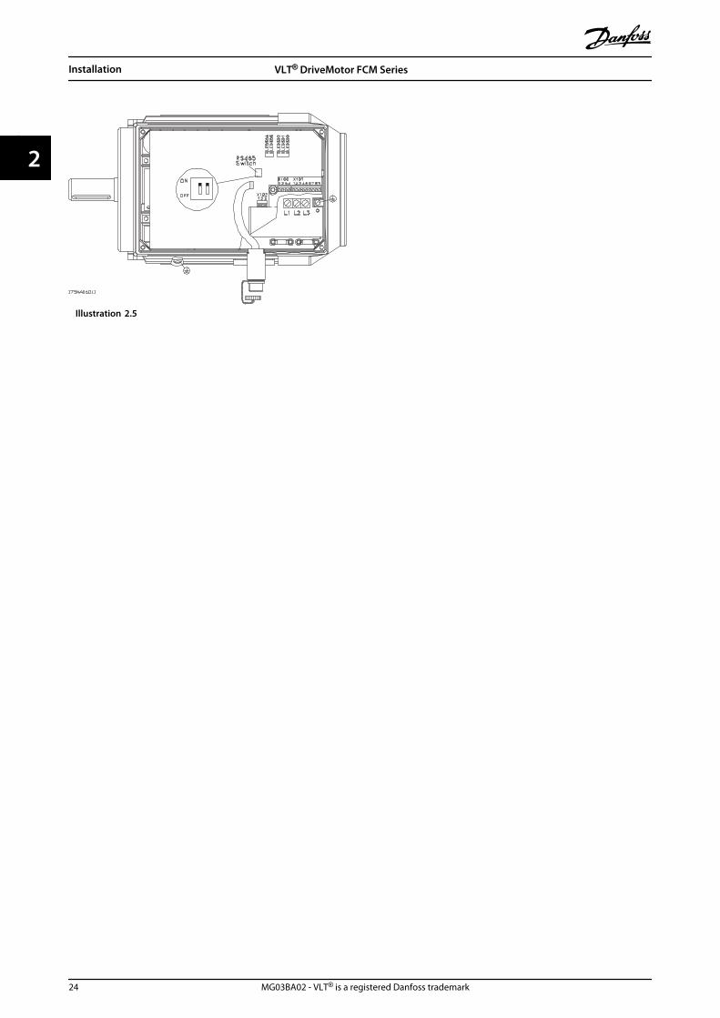
Illustration 2.5
Installation VLT® DriveMotor FCM Series
24 MG03BA02 - VLT® is a registered Danfoss trademark
22

2.3.2 Plug Kit (175N2545)
PurposeTo make a plugable connection between LCP 2 and FCM300.Used together with cable for plug kit 175N0162.
Illustration 2.6
2.3.3 Remote Mounting Kit (175N0160)
Illustration 2.7 Connections
Colour of wire/ Terminal X100/ D-sub pin
yellow 1 8
green 2 9
red 3 2
blue 4 3
Table 2.22
2.3.4 Remote Mounting Kit Cont.
Illustration 2.8
Illustration 2.9
Installation VLT® DriveMotor FCM Series
MG03BA02 - VLT® is a registered Danfoss trademark 25
2 2

2.3.5 Potentiometer Option (177N0011)
Option to control the reference by means of a potenti-ometer. The option is mounted instead of a cable bracket.The potentiometer is operated by removing the blind plugto set the desired reference, and then mount the blindplug again.
Illustration 2.10
Colour of wire Terminal on X101
White 2 (analog input)
Red 8 (0 V)
Black 7 (+10 V)
Table 2.23
2.3.6 Local Operation Pad (LOP)(175N0128) IP65
Illustration 2.11
Colour of wire Terminal Function
White 2 Reference
Brown 3 Reset
Purple* or Grey 4See Illustration 2.11
Green 5
Red 6 +24 V
Yellow 7 +10 V
Blue 8 Ground
* Can be orange in some cables
Table 2.24 Wiring
Illustration 2.12 Local Operation Panel (LOP) 175N0128 IP 65
Illustration 2.13 Fixture for LOP 175N2717 (included in175N0128)
Installation VLT® DriveMotor FCM Series
26 MG03BA02 - VLT® is a registered Danfoss trademark
22

Functions/settings Key I (Start) Key II (Start)
Key (Stop)
Default - Dual speed operation (connect purplewire):No changes to factory setting.
Run on set reference(+/-)
Run on 10 Hz** jogspeed
Stop (and reset* - if trip)
Function 2 - Dual mode operation (connectpurple wire):Select desired modes of operation in Setups 1and 2 (use para. 4-6) Parameter 335 = 18 (selectSetup)
Run with Setup 1 Run with Setup 2 Stop (and reset* - if trip)
Function 3 - Dual direction operation (connectgrey wire):Parameter 335 = 10 (start reversing) Parameter200 = 1 (both directions)
Run forward Run reverse Stop (and reset* - if trip)
Table 2.25
*If no reset is required, do not connect the brown wire
**or set parameter 213
Use the [+[/[-] keys to set reference
At power up the unit will always be in stop mode. Setreference will be stored during power down. If permanentstart mode is desired, connect terminal 6 to terminal 4 anddo not connect purple/grey wire to terminal 4. This meansthe stop function on LOP is disabled.
NOTICEAfter fitting, cut off or isolate excess wire.
Installation VLT® DriveMotor FCM Series
MG03BA02 - VLT® is a registered Danfoss trademark 27
2 2

3 Programming
3.1 Parameters
3.1.1 Control Panel (175NO131)
The FC motor optionally features a Local Control Panel-LCP 2 which makes up a complete interface for operationand monitoring of the FC motor.IP 65 on front.
3.1.2 LCP Installation
The LCP 2 is connected to the terminal X100, 1-4 (seeseparate instruction MI03AXYY).
1. Service Plug Kit (175N2546) (see 2.3.1 Service PlugKit (175N2546)) and cable 175N0162
2. Plug kit (175N2545) (see 2.3.2 Plug Kit(175N2545)) and cable 175N0162
3. Remote mounting kit (175N0160) (see 2.3.4 Remote Mounting Kit Cont.)
3.1.3 LCP Functions
The functions of the control panel can be divided intothree groups:
• Display
• Keys for changing program parameters
• Keys for local operation
All data are indicated by means of a 4-line alphanumericdisplay, which in normal operation is able show 4measurements and 3 operating conditions continuously.During programming, all the information required forquick, effective parameter Set-up of the FC motor will bedisplayed. As a supplement to the display, there are threeLEDs for voltage, warning and alarm. All programparameters of the FC motor can be changed immediatelyfrom the control panel, unless this function has beenblocked via parameter 018.
Illustration 3.1
3.1.4 Display
The LCD display is back lit and has a total of 4 alpha-numeric lines together with a box that shows the directionof rotation (arrow) and the chosen Set-up as well as theSet-up in which programming is taking place if that is thecase.
Illustration 3.2
Programming VLT® DriveMotor FCM Series
28 MG03BA02 - VLT® is a registered Danfoss trademark
33

1st line shows up to 3 measurements continuously innormal operating status or a text which explains the 2ndline.
2nd line shows a measurement with related unit contin-uously, regardless of status (except in the case of alarm/warning).
3rd line is normally blank and is used in the menu modeto show the selected parameter number or parametergroup number and name.
4th line is used in operating status for showing a statustext or in data change mode for showing the value of theselected parameter.
Illustration 3.3
An arrow indicates the direction of rotation of the motor.Furthermore, the Set-up which has been selected as theActive Setup in parameter 004 is shown. Whenprogramming another Set-up than the Active Set-up, thenumber of the Set-up which is being programmed willappear to the right. This second Set-up number will flash.
3.1.5 LEDs
At the bottom of the control panel is a red alarm LED anda yellow warning LED, as well as a green voltage LED.
Illustration 3.4
If certain threshold values are exceeded, the alarm and/orwarning lamp lights up together with a status and alarmtext on the control panel.The voltage LED is activated when the FC motor receivesvoltage; at the same time the rear lighting of the displaywill be on.
3.1.6 Control Keys
The control keys are divided into functions. This meansthat the keys between display and indicator LEDs are usedfor parameter Setup, including choice of display indicationduring normal operation.
Illustration 3.5
Keys for local control are found under the indicator LEDs.
Illustration 3.6
3.1.7 Control Key Functions
[DISPLAY/STATUS] is used for selectingthe mode of display or for changing backto Display mode from either the Quickmenu mode or the Menu mode.[QUICK MENU] is used for programmingthe parameters that belong under theQuick menu mode. It is possible to switchdirectly between Quick menu mode andMenu mode.[MENU] is used for programming allparameters. It is possible to switchdirectly between Menu mode and Quickmenu mode.
Table 3.1
Programming VLT® DriveMotor FCM Series
MG03BA02 - VLT® is a registered Danfoss trademark 29
3 3

[CHANGE DATA] is used for changing theparameter selected either in the Menumode or the Quick menu mode.[CANCEL] is used if a change of theselected parameter is not to be carriedout.[OK] is used for confirming a change ofthe parameter selected.
[+]/[-] is used for selecting parameter andfor changing the chosen parameter or forchanging the read out in line 2.[<][>] is used for selecting group and tomove the cursor when changingnumerical parameters.[STOP/RESET] is used for stopping or forresetting the FC motor after a drop-out(trip). Can be selected via parameter 014to be active or inactive. If stop isactivated, line 2 will flash, and [START]must be activated.
Table 3.2
NOTICEPressing [STOP/RESET] will prevent motor from runningalso with disconnected LCP 2. Restarting is only possiblevia the LCP 2 [START] key.
[JOG] overrides the output frequency to apreset frequency while the key is keptdown. Can be selected via parameter 015to be active or inactive.[FWD/REV] changes the direction ofrotation of the motor, which is indicatedby means of the arrow on the displayalthough only in Local. Can be selectedvia parameter 016 to be active or inactive(parameter 013 must be set to [1] or [3]and parameter 200 set to [1].[START] is used for starting the FC motorafter stop via the [Stop] key. Is alwaysactive, but cannot override a stopcommand given via the terminal strip.
Table 3.3
NOTICEIf the keys for local control have been selected as active,they will remain active both when the frequency hasbeen set for Local Control and for Remote Control viaparameter 002, although with the exception of [FWD/REV], which is only active in Local operation.
NOTICEIf no external stop function has been selected and the[STOP] key has been selected as inactive via parameter014, the FC motor can be started and can only bestopped by disconnecting the voltage to the motor.
3.1.8 Display Read-out State
The display read-out state can be varied - see3.1.15 Parameter Groups - depending on whether the FCmotor is in normal operation or is being programmed.
3.1.9 Display Mode
In normal operation, up to 4 different operating variablescan be indicated continuously: 1.1 and 1.2 and 1.3 and 2,and in line 4 the present operating status or alarms andwarnings that have arisen.
19
5N
A1
13
.10VAR 2
SETUP
1
STATUS
VAR 1.1 VAR 1.2 VAR 1.3
Illustration 3.7
3.1.10 Display Mode - Selection of Read-out State
There are three options in connection with the choice ofread-out state in the Display mode - I, II and III. The choiceof read-out state determines the number of operatingvariables read out.
Read-outstate:
I: II: III:
Line 1 Description foroperatingvariable in line2
Data value for3 operatingvariables inline 1
Description for3 operatingvariables inline 1
Table 3.4
Table 3.5 gives the units linked to the variables in the firstand second line of the display (see parameter 009).
Programming VLT® DriveMotor FCM Series
30 MG03BA02 - VLT® is a registered Danfoss trademark
33

Operating variable: Unit
Reference [%]
Reference [unit]*
Feedback [unit]*
Frequency [Hz]
Frequency x scaling [-]
Motor current [A]
Torque [%]
Power [kW]
Power [HP]
Motor voltage [V]
DC-link voltage [V]
FC thermal [%]
Hours run [Hours]
Input status, dig. Input [Binary code]
External reference [%]
Status word [Hex]
Heat sink temp. [ºC]
Alarm word [Hex]
Control word [Hex]
Warning word 1 [Hex]
Warning word 2 [Hex]
Analog input 1 [mA]
Analog input 2 [V]
*) Select in parameter 416. The unit is shown in readout state 1line 1 otherwise 'U' is shown.
Table 3.5
Operating variables 1.1 and 1.2 and 1.3 in the first line, andoperating variable 2 in the second line are selected viaparameter 009, 010, 011 and 012.
Read-out state I:This read-out state is standard afterstarting up or after initialisation.
50.0 Hz
FREQUENCY
MOTOR IS RUNNING
Line 2 gives the data value of an operating variable withrelated unit, and line 1 provides a text which explains line2, cf. table. In the example, Frequency has been selectedas variable via parameter 009. During normal operationanother variable can immediately be read out by using the[+]/[-] keys.Read-out state II:
Switching between read-out states I and II is effected bypressing the [DISPLAY/STATUS] key.
MOTOR IS RUNNING
50.0 Hz
24.3% 30.2% 13.8A
In this state, data values for four operating values areshown at the same time, giving the related unit, cf. table.In the example, Reference, Torque, Current and Frequencyare selected as variables in the first and second line.Read-out state III:This read-out state can be held as long as the [DISPLAY/STATUS] key is pressed. When the key is released, thesystem switches back to Read-out state II, unless the key ispressed for less than approx. 1 s.
50.0 HzSETUP
1
MOTOR IS RUNNING
REF% TORQUE CURR A
This is where parameter names and units for operatingvariables in the first line are given - operating variable 2remains unchanged.
3.1.11 Quick Menu Mode Versus MenuMode
The FC motor series can be used for practically allassignments, which is why the number of parameters isquite large. Also, this series offers a choice between twoprogramming modes - a Menu mode and a Quick menumode.
• The Quick menu takes the user through anumber of parameters that may be enough toget the motor to run nearly optimally, if thefactory setting for the other parameters takes thedesired control functions into account, as well asthe configuration of signal inputs/outputs (controlterminals).
• The Menu mode makes it possible to select andchange all parameters at the user's option.
Programming VLT® DriveMotor FCM Series
MG03BA02 - VLT® is a registered Danfoss trademark 31
3 3

However, some parameters will be "missing",depending on the choice of configuration(parameter 100), e.g. open loop hides all the PIDparameters.
In addition to having a name, each parameter is linked upwith a number which is the same regardless of theprogramming mode. In the Menu mode, the parametersare divided into groups, with the first digit of theparameter number (from the left) indicating the groupnumber of the parameter in question.
Regardless of the mode of programming, a change of aparameter will take effect and be visible both in the Menumode and in the Quick menumode.
3.1.12 Quick Setup via Quick Menu
The Quick Setup starts with pressing the [Quick Menu] key,which brings out the following read-out on the display:
50.0 Hz SETUP
1
QUICK MENU X OF Y
001 LANGUAGE
ENGLISH
At the bottom of the display, the parameter number andname are given together with the status/value of the firstparameter under Quick Setup. The first time the [QuickMenu] key is pressed after the unit has been switched on,the read-outs will always start at pos. 1 - see Table 3.6.
3.1.13 Parameter Selection
The selection of parameter is effected by means of the[+]/[-] keys. The following parameters are accessible:
Pos.: No.: Parameter: Unit:1 001 Language
2 200 Direction of rotation
3 101 Torque characteristic
4 204 Min. reference [Hz]
5 205 Max. reference [Hz]
6 207 Ramp up time [s]
7 208 Ramp down time [s]
8 002 Local/remote control
9 003 Local reference
Pos.: No.: Parameter: Unit:10 500 Bus address
Table 3.6 Parameter Selection
3.1.14 Menu Mode
The Menu mode is started by pressing the [Menu] key,which produces the following read-out on the display:
50.0 Hz
FREQUENCY
0 KEYB.&DISPLAY
Illustration 3.8
Line 3 on the display shows the parameter group numberand name.
3.1.15 Parameter Groups
In the Menu mode the parameters are divided into groups.Selection of parameter group is effected by means of the[<][>] keys.The following parameter groups are accessible:
Group no. Parameter group
0 Operation & Display
1 Load & Motor
2 References & Limits
3 Inputs & Outputs
4 Special functions
5 Serial communication
6 Technical functions
*For information on parameter group 800 and 900 for PROFIBUS,please see the FCM Profibus manual MG03EXYY.
Table 3.7
Programming VLT® DriveMotor FCM Series
32 MG03BA02 - VLT® is a registered Danfoss trademark
33

When the desired parameter group has been selected,each parameter can be selected with the [+]/[-] keys:
FREQUENCY
001 LANGUAGE
ENGLISH
50.0 Hz
Illustration 3.9
The 3rd line of the display shows the parameter numberand name, while the status/value of the selectedparameter is shown in line 4.
3.1.16 Changing Data
Regardless of whether a parameter has been selectedunder the Quick menu or the Menu mode, the procedurefor changing data is the same. Pressing [Change Data] keygives access to changing the selected parameter, followingwhich the underlining in line 4 will flash on the display.The procedure for changing data depends on whether theselected parameter represents a numerical data value or atext value.
3.1.17 Changing a Text Value
If the selected parameter is a text value, the text value ischanged by means of the [+]/[-] keys.
50.0 Hz
FREQUENCY
001 LANGUAGE
ENGLISH
Illustration 3.10
The bottom display line shows the text value that will beentered (saved) when acknowledgement is given [OK].
3.1.18 Infinitely Variable Change ofNumeric Data Value
If the selected parameter represents a numeric data value,a digit is first selected by means of the [<][>] keys.
50.0 Hz SETUP
1
FREQUENCY
130 START FREQUENCY
09.0 HZ
Illustration 3.11
Then the selected digit is changed infinitely with the [+]/[-]keys:
50.0 Hz SETUP
1
FREQUENCY
130 START FREQUENCY
10.0 HZ
Illustration 3.12
The selected digit is indicated by the digit flashing. Thebottom display line shows the data value that will beentered (saved) when signing off with [OK].
Programming VLT® DriveMotor FCM Series
MG03BA02 - VLT® is a registered Danfoss trademark 33
3 3

3.1.19 Menu Structure
175ZA446.11
DISPLAY MODE
MENU MODE QUICK MENU MODE
DATA CHANGE MODE
ss
s s
s
s
ss
s
Choice of
parameter
DATA MODE
Choice of
data value
Choice of
group
VAR 2
STATUS
VAR 1.1 VAR 1.2 VAR 1.3
50.0 HZ
FREQUENCY
0 KEYB.&DISPLAY
50.0 HZ001 LANGUAGE
ENGLISH
FREQUENCY
001 LANGUAGE
ENGLISH
50.0 HZ
FREQUENCY
001 LANGUAGE
ENGLISH
50.0 HZ001 LANGUAGE
ENGLISH
DATA CHANGE MODE
50.0 HZ
QUICK MENU 1 OF 13
QUICK MENU 1 OF 13
Illustration 3.13
Programming VLT® DriveMotor FCM Series
34 MG03BA02 - VLT® is a registered Danfoss trademark
33

Programming VLT® DriveMotor FCM Series
MG03BA02 - VLT® is a registered Danfoss trademark 35
3 3

3.1.20 Parameter Group 0-** Operation/Display
001 Language
Value:
English (ENGLISH) [0]
German (DEUTSCH) [1]
French (FRANCAIS) [2]
Danish (DANSK) [3]
Spanish (ESPAÑOL) [4]
Italian (ITALIANO) [5]
State when delivered may vary from factory setting.
Function:The choice in this parameter defines the language to beused on the display.
Description of choice:There is a choice of [0] English, [1] German, [2] French, [3]Danish, [4] Spanish and [5] Italian.
002 Local/remote control
Value:
Remote control (REMOTE) [0]
Local control (LOCAL) [1]
Function:There is a choice of two methods of controlling the FCmotor:[0] Remote control and [1] Local control.
Description of choice:If [0] Remote control is selected, the FC motor can becontrolled via:
1. The control terminals or the serial communicationport .
2. The [Start] key. However, this cannot overruleStop commands (also start-disable) entered viathe digital inputs or the serial communicationport.
3. The [Stop], [Jog] and [Reset] keys, provided thatthese are active (see parameters 014, 015 and017).
If [1] Local control is selected, the FC motor can becontrolled via:
1. The [Start] key. However, this cannot overrideStop commands on the digital terminals (if [2] or[4] has been selected in parameter 013).
2. The [Stop], [Jog] and [Reset] keys, provided thatthese are active (see parameters 014, 015 and017).
3. The [FWD/REV] key, provided that this has beenactivated in parameter 016 and that in parameter013 a choice of [1] or [3] has been made.
4. Via parameter 003 the local reference can becontrolled by means of the "Arrow up" and"Arrow down" keys.
003 Local reference
Value:Par 013 set for [1] or [2]:0 - f MAX 000.000Par 013 set for [3] or [4] and par. 203 = [0]set for:RefMIN - RefMAX 000.000Par 013 set for [3] or [4] and par. 203 = [1]set for:-RefMAX - + RefMAX 000.000
Function:This parameter allows manual setting of the desiredreference value (speed or reference for the selected config-uration, depending on the choice made in parameter 013).The unit follows the configuration selected in parameter100, provided that [3] Process regulation, closed loop hasbeen selected.
Description of choice:[1] Local must be selected in parameter 002 for thisparameter to be used.The set value is saved in the case of a voltage dropout, seeparameter 019.In this parameter Data Change Mode is not exitedautomatically (after time out).Local reference cannot be set via the serial communicationport.
004 Active Setup
Value:
Factory Setup (FACTORY SETUP) [0]
Setup 1 (SETUP 1) [1]
Setup 2 (SETUP 2) [2]
Multi Setup (MULTI SETUP) [5]
Function:The choice in this parameter defines the Setup numberyou want to control the functions of the FC motor.All parameters can be programmed in two individualparameter Setups, Setup 1 and Setup 2. In addition, thereis a pre-programmed Setup, called Factory Setup, thatcannot be modified.
Description of choice:[0] Factory Setup contains the factory data. Can be used asa data source if the other Setups are to be returned to aknown state.Parameters 005 and 006 allow copying from one Setup tothe other.[1] Setups 1 and [2] 2 are two individual Setups that can beselected as required.[5] Multi-Setup is used if remote-mounting switchingbetween Set-ups is desired. Terminals 2, 3, 4, and 5 as well
Programming VLT® DriveMotor FCM Series
36 MG03BA02 - VLT® is a registered Danfoss trademark
33

as the serial communication port can be used for switchingbetween Setups.
005 Programming Setup
Value:
Factory Setup (FACTORY SETUP) [0]
Setup 1 (SETUP 1) [1]
Setup 2 (SETUP 2) [2]
Active Setup (ACTIVE SETUP) [5]
Function:The choice is of the Set-up in which programming (changeof data) is to occur during operation. It is possible toprogramme the two Set-ups independently of the Set-upselected as the Active Set-up (selected in parameter 004).
Description of choice:The [0] Factory Setup contains the factory data and can beused as a data source if the other Set-ups are to bereturned to a known state.[1] Setups 1 and [2] 2 are individual Setups which can beused as required. They can be programmed freely,regardless of the Set-up selected as the Active Set-up andthus controlling the functions of the FC motor.
006 Copying of Setups
Value:
No copying (NO COPY) [0]
Copy to Setup 1 from # (COPY TO SETUP 1) [1]
Copy to Setup 2 from # (COPY TO SETUP 2) [2]
Copy to Setup all from # (COPY TO ALL) [5]
# = the Setup selected in parameter 005
Function:A copy is made from the Set-up selected in parameter 005to one of the other Set-ups or to all the other Set-upssimultaneously.
007 LCP copy
Value:
No copying (NO COPY) [0]
Upload all parameters (UPLOAD ALL PARAM) [1]
Download all parameters (DOWNLOAD ALL) [2]
Download power-independent par.(DOWNLOAD SIZE INDEP.) [3]
Function:Parameter 007 is used if it is desired to use the integratedcopying function of the control panel. You can thereforeeasily copy parameter value(s) from one FC motor toanother.
Description of choice:Select [1] Upload all parameters if all parameter values areto be transmitted to the control panel. Select [2] Downloadall parameters if all transmitted parameter values are to becopied to the FC motor on which the control panel hasbeen mounted. Select [3] Download power-independent par.
if only the power-independent parameters are to bedownloaded. This is used if downloading to a FC motorthat has a different rated power than the one from wherethe parameter Set-up originates.
008 Display scaling of motor frequency
Value:
0.0-100.00 [1-10000]
1.00 [100]
Function:This parameter chooses the factor to be multiplied by themotor frequency, fM, for presentation in the display, whenparameters 009-012 have been set for Frequency x Scaling[5].
Description of choice:Set the desired scaling factor.
009 Display line 2
Value:
None [0]
Reference [%] (REFERENCE [%]) [1]
Reference [unit] (REFERENCE [UNIT]) [2]
Feedback [unit] (FEEDBACK [UNIT]) [3]
Frequency [Hz] (FREQUENCY [Hz]) [4]
Frequency x Scaling [-] (FREQUENCY X SCALE) [5]
Motor current [A] (MOTOR CURRENT [A]) [6]
Torque [%] (TORQUE [%]) [7]
Power [kW] (POWER [kW]) [8]
Power [HP] (POWER [hp] [US]) [9]
Motor voltage [V] (MOTOR VOLTAGE [V]) [11]
DC link voltage [V] (DC LINK VOLTAGE [V]) [12]
Thermal load, FC [%] (FC THERMAL [%]) [14]
Hours run [Hours] (RUNNING HOURS) [15]
Digital input [Binary code] (DIGITAL INPUT [BIN]) [16]
External reference [%] (EXTERNAL REF [%]) [21]
Status word [Hex] (STATUS WORD [HEX]) [22]
Heat sink temp. [°C] (HEATSINK TEMP [°C]) [25]
Alarm word [Hex] (ALARM WORD [HEX]) [26]
Control word [Hex] (CONTROL WORD [HEX]) [27]
Warning word 1 [Hex](WARNING WORD 1 [HEX]) [28]
Warning word 2 [Hex](EXTENDED STATUS WORD [HEX]) [29]
Analog input 1 [mA] (ANALOG INPUT 1 [mA]) [30]
Analog input 2 [V] (ANALOG INPUT 2 [V]) [31]
Function:This parameter allows a choice of the data value to bedisplayed in line 2 of the display.Parameters 010-012 enable the use of three additional datavalues to be displayed in line 1.For display read-outs, press the [DISPLAY/STATUS] button,see 3.1.7 Control Key Functions.
Programming VLT® DriveMotor FCM Series
MG03BA02 - VLT® is a registered Danfoss trademark 37
3 3

Description of choice:Reference [%] corresponds to the total reference (sum ofdigital/analogue/preset/bus/freeze ref./ catch-up and slow-down).Reference [unit] gives the sum of the references using theunit stated on the basis of configuration in parameter 100(Hz, Hz and rpm).Feedback [unit] gives the status value of terminal 1 and 2using the unit/scale selected in parameter 414, 415 and416.Frequency [Hz] gives the motor frequency, i.e. the outputfrequency to the motor.Frequency x Scaling [-] corresponds to the present motorfrequency fM multiplied by a factor (scaling) set inparameter 008.Motor current [A] states the phase current of the motormeasured as effective value.Torque [%] gives the current motor load in relation to therated motor torque.Power [kW] states the actual power consumed by themotor in kW.Power [HP] states the actual power consumed by themotor in HP.Motor voltage [V] states the voltage supplied to the motor.DC link voltage [V] states the intermediate circuit voltage inthe FC motor.Thermal load, FC [%] states the calculated/ estimatedthermal load on the FC motor. 100% is the cut-out limit.Hours run [Hours] states the number of hours that themotor has run since the latest reset in parameter 619.Digital input [Binary code] states the signal states from the4 digital terminals (2, 3, 4 and 5). Input 5 corresponds tothe bit at the far left. '0' = no signal, '1' = connected signal.External reference [%] gives the sum of the externalreference as a percentage (the sum of analogue/ pulse/bus).Status word [Hex] gives the status word sent via the serialcommunication port in Hex code from the FC motor.Heat sink temp. [°C] states the present heat sinktemperature of the FC motor. The cut-out limit is 90 ± 5°C;cutting back in occurs at 60 ± 5°C.Alarm word [Hex] indicates one or several alarms in a Hexcode. See 4.2.4 Warning Word, Extended Status Word andAlarm Word.Control word [Hex] indicates the control word for the FCmotor. See 3.6 Serial communication - FCM 300 DesignGuide.Warning word 1 [Hex] indicates one or more warnings in aHex code. See 4.2.4 Warning Word, Extended Status Wordand Alarm Word for further information.Extended status word [Hex] indicates one or more statusstates in a Hex code. See 4.2.4 Warning Word, ExtendedStatus Word and Alarm Word for further information.Analog input 1 [mA] states the signal value on terminal 1.
Analog input 2[V] states the signal value on terminal 2.
010 Display line 1.1
Value:
Reference [%] [1]
See parameter 009.
Function:This parameter enables a choice of the first of three datavalues to be shown on the display, line 1, position 1.
Description of choice:There is a choice of 24 different data values, see parameter009.
011 Display line 1.2
Value:
Motor current [A] [1]
See parameter 009
Function:This parameter enables a choice of the second of the threedata values to be shown on the display, line 1, position 2.For Display read-outs, press the [DISPLAY/STATUS] button,see 3.1.7 Control Key Functions.
Description of choice:There is a choice of 24 different data values, see parameter009.
012 Display line 1.3
Value:
Power [kW] [8]
See parameter 009
Function:This parameter enables a choice of the third of the threedata values to be shown on the display, line 1, position 3.Display read-outs are made by pressing the [DISPLAY/STATUS] button, see 3.1.7 Control Key Functions.
Description of choice:There is a choice of 24 different data values, see parameter009.
013Local Control/Configuration as parameter100
Value:
Local not active (DISABLE) [0]
LCP control and open loop.(LCP CTRL/OPEN LOOP) [1]
LCP digital control and open loop.(LCP+DIG CTRL/OP.LOOP) [2]
LCP control/as parameter 100.(LCP CTRL/AS P100) [3]
LCP digital control/as parameter 100.(LCP+DIG CTRL/AS P100) [4]
Programming VLT® DriveMotor FCM Series
38 MG03BA02 - VLT® is a registered Danfoss trademark
33

Function:This is where the desired function is to be selected if Localcontrol has been chosen in parameter 002. See also thedescription of parameter 100.
Description of choice:If Local not active [0] is selected, a possible setting of Localreference via parameter 003 is blocked. It is only possible tochange to Local not active [0] from one of the other settingoptions in parameter 013, when the FC motor has been setto Remote control [0] in parameter 002.LCP control and open loop [1] is used when the speed is tobe adjustable (in Hz) via parameter 003, when the FCmotor has been set to Local control [1] in parameter 002.If parameter 100 has not been set to Speed regulation openloop [0], switch to Speed regulation open loop [0].LCP digital control and open loop [2] functions as LCPcontrol and open loop [1], the only difference being thatwhen parameter 002 has been set to Local operation [1],the motor is controlled via the digital inputs.LCP control/as parameter 100 [3] is selected if the referenceis to be set via parameter 003.LCP digital control/as parameter 100 [4] functions as LCPcontrol/as parameter 100 [3], although, when parameter002 has been set to Local operation [1], the motor may becontrolled via the digital inputs.
The present motor frequency and direction of rotationmust be maintained. If the present direction of rotationdoes not correspond to the reversing signal (negativereference), the motor frequency fM will be set at 0 Hz.Shift from LCP digital control and open loop to Remotecontrol:The selected configuration (parameter 100) will be active.Shifts are effected without any abrupt movement.Shift from Remote control to LCP control/as parameter 100or LCP digital control/as parameter 100.The present reference will be maintained. If the referencesignal is negative, the local reference will be set at 0.Shift from LCP control/as parameter 100 or LCP remotecontrol as parameter 100 to Remote control.The reference will be replaced by the active referencesignal from the remote control..
014 Local stop
Value:
Not possible (DISABLE) [0]
Possible (ENABLE) [1]
Function:This parameter disables/enables the local stop function inquestion from the control panel. This key is used whenparameter 002 has been set for [0] Remote control or [1]Local .
Description of choice:If [0] Disable is selected in this parameter, the [STOP] keywill be inactive.
015 Local jog
Value:
Not possible (DISABLE) [0]
Possible (ENABLE) [1]
Function:In this parameter, the jog function can be enabled/disabled on the control panel.
Description of choice:If [0] Disable is selected in this parameter, the [JOG] keywill be inactive.
016 Local reversing
Value:
Not possible (DISABLE) [0]
Possible (ENABLE) [1]
Function:In this parameter, the reversing function can be enabled/disabled on the control panel. This key can only be used ifparameter 002 has been set to [1] Local operation andparameter 013 to [1] LCP control with open loop or [3] LCPcontrol as parameter 100.
Description of choice:If [0] Disable is selected in this parameter, the [FWD/ REV]key will be inactive.See parameter 200.
017 Local reset of trip
Value:
Not possible (DISABLE) [0]
Possible (ENABLE) [1]
Function:In this parameter, the reset function can be selected/removed from the keyboard. This key can be used whenparameter 002 has been set for [0] Remote control or [1]Local control .
Description of choice:If [0] Disable is selected in this parameter, the [RESET] keywill be inactive.
018 Lock for data change
Value:
Not locked (NOT LOCKED) [0]
Locked (LOCKED) [1]
Function:In this parameter, the software can "lock" the control,which means that data changes cannot be made via LCP 2(however, this is still possible via the serial communicationport).
Programming VLT® DriveMotor FCM Series
MG03BA02 - VLT® is a registered Danfoss trademark 39
3 3

Description of choice:If [1] Locked is selected, data changes cannot be made.
019 Operating state at power up, local control
Value:
Auto restart, use saved ref. (AUTO RESTART) [0]
Forced stop, use saved ref. (LOCAL=STOP) [1]
Forced stop, set ref. to 0 (LOCAL=STOP, REF=0) [2]
Function:Setting of the desired operating mode when the mainsvoltage is reconnected.This function can only be active in connection with [1]Local control in parameter 002.
Description of choice:[0] Auto restart, use saved ref. is selected if the unit is tostart up with the same local reference (set in parameter003) and the same start/stop conditions (given via the[Start/Stop] keys) that the FC motor had before it wasswitched off.[1] Forced stop, use saved ref. is used if the unit is to remainstopped when the mains voltage is connected, until the[START] key is pressed. After the start command, the localreference used is set in parameter 003.[2] Forced stop, set ref. to 0 is selected if the unit is toremain stopped when the mains voltage is connected.Local reference (parameter 003) is reset.
3.2.1 Parameter Group 1-** Load/Motor
100 Configuration
Value:
Speed, open loop mode (SPEED OPEN LOOP) [0]
Process, closed loop mode(PROCESS CLOSED LOOP) [1]
Function:This parameter is used for selecting the configuration towhich the FC motor is to be adapted.
Description of choice:If [0] Speed, open loop mode is selected, a normal speedcontrol (without feedback signal) is obtained, but withautomatic slip compensation, ensuring a nearly constantspeed at varying loads. Compensations are active, but maybe disabled as required in parameter 133 - 136.If [3] Process, closed loop mode is selected, the internalprocess regulator will be activated, thereby enablingaccurate regulation of a process with respect to a givenprocess signal. The process signal can be set using theactual process unit or as a percentage. A feedback signalmust be supplied from the process, and the processsetpoint must be adjusted. In process closed loop bothdirections is not allowed in parameter 200.
101 Torque characteristics
Value:
Constant torque (CONSTANT TORQUE) [1]
Variable torque: low (VAR.TORQUE: LOW) [2]
Var. torque: medium (VAR.TORQUE: MEDIUM) [3]
Variable torque: high (VAR.TORQUE: HIGH) [4]
Function:In this parameter, the principle for adjusting the U/fcharacteristics of the FC motor to the torque characteristicsof the load is selected.
Description of choice:If [1] Constant torque is selected, a load-dependent U/fcharacteristic is obtained in which the output voltage isincreased in the case of an increasing load (current) so asto maintain constant magnetisation of the motor.Select [2] Variable torque low, [3] Variable torque medium or[4] Variable torque high if the load is square (centrifugalpumps, fans).
Illustration 3.14
102 Motor power
Value:
XX.XX kW - depends on the FC motor [XXXX]
Function:Read only parameter.
103 Motor voltage
Value:
XX V- depends on the FC motor [XX]
Function:Read only parameter.
104 Motor frequency
Value:
XX.X Hz - depends on the FC motor [XXX]
Function:Read only parameter.
105 Motor current
Value:
XX.X X A- depends on the FC motor. [XXXX]
Programming VLT® DriveMotor FCM Series
40 MG03BA02 - VLT® is a registered Danfoss trademark
33

Function:Read only parameter.
106 Rated motor speed
Value:
XX rpm - depends on the FC motor [XX]
Function:Read only parameter.
117 Resonance damping
Value:
OFF - 100% [OFF -100]
OFF%. [OFF]
Function:It is possible to optimise the resonance damping. Thegrade of the influence is adjusted in this parameter.The value may be set between 0% (OFF) and 100%.100% corresponds to the unit dependent max. allowedproportional gain. Default value is OFF.
Description of functionality:The system torque is estimated based on the DC-link andfed back to a proportional gain controller.At a unit dependent level of active motor current thecontroller is disabled.
Description of choice:Set the grade of proportional gain for the torque feedbackbetween 0% (OFF) and 100%.
118 Resonance damping cut out
Value:
0-200% [0-200]
Motor dependent
Function:High-frequency resonance can be eliminated by settingparameter 117 and 118.
Description of choice:Adjust the percentage of load from where the resonancedamping function should no longer be active.
126 DC braking time
Value:
0.0 - 60.0 sec. [0-600]
10.0 sec. [100]
DC braking see P132
Function:This parameter is for setting the DC braking time for whichthe DC braking voltage (parameter 132) is to be active.0.0 sec. = OFF
Description of choice:Set the desired time.
127 DC brake cut-in frequency
Value:
0.0-fMAX (parameter 202) [0 -]
0.0 Hz = OFF [0]
DC braking see P132
Function:This parameter is for setting the DC brake cut-in frequencyat which the DC braking voltage (parameter 132) is to beactive, in connection with a Stop command.
Description of choice:Set the desired frequency.
128 Motor thermal protection
Value:
No protection (NO PROTECTION) [0]
Function:Read only parameterPlease refer to section FCM 300 Thermal protection.
132 DC braking voltage
Value:
0-100% [0-100]
0% [0]
Function:DC braking:If the stator in an asynchronous is supplied with DCvoltage, a braking torque will arise.The braking torque depends on the selected DC brakingvoltage.For applying a braking torque by means of DC braking therotating field (AC) in the motor is exchanged with astationary field (DC)˙The DC braking will be active when below cut in frequencyand stop is activated at the same time. P126, P127 andP132 are used for the control of the DC braking.The DC braking can also be activated directly by a digitalinput.Function:The braking torque depends on the selected DC brakingvoltage. The DC braking voltage is stated as a percentageof maximum braking voltage.
Description of choice:Set the desired voltage as a specified percentage ofmaximum braking voltage.
133 Start voltage
Value:
0.00-100.00 V [0-10000]
Depends on motor
Function:You can set the motor voltage below the field weakeningpoint independently of the motor current. Use thisparameter to compensate too low starting torque.The start voltage is the voltage at 0 Hz.
Programming VLT® DriveMotor FCM Series
MG03BA02 - VLT® is a registered Danfoss trademark 41
3 3

Description of choice:Set the desired start voltage.
134 Load compensation
Value:
0.0-300.0% [0-3000]
100.0% [1000]
Function:In this parameter, the load characteristic is set. Byincreasing the load compensation, the motor is given anextra voltage and frequency supplement at increasingloads. This is used e.g. in motors/applications in whichthere is a big difference between the full-load current andidle-load current of the motor.
Description of choice:If the factory setting is not adequate, load compensationmust be set to enable the motor to start at the given load.
CAUTIONShould be set to 0% in case of quick load changes. Toohigh load compensation may lead to instability.
135 U/f ratio
Value:
0.00-20.00 V/Hz [0-2000]
Motor dependent
Function:The output voltage to the motor can be adjusted on alinear basis from 0 to rated frequency.
Illustration 3.15
136 Slip compensation
Value:
-500.0-+500.0% [-5000 - +5000]
100.0% [1000]
Function:The rated slip compensation (factory setting) is calculatedon the basis of the motor parameters. In parameter 136the slip compensation can be adjusted in detail.Optimizing makes the motor speed less load dependent.
This function is not active at the same time as variabletorque (parameter 101).
Description of choice:Enter a % value of rated slip compensation.
137 DC holding voltage
Value:
0-100% [0-100]
0 (OFF)% [0]
Function:This parameter is used to uphold the motor function(holding torque) or to pre-heat the motor. DC holdingvoltage is active at stopped motor when it is set at a valuewhich is different from 0. Coasting stop will deactivate thefunction.
Description of choice:Enter a percentage value.
138 Brake cut out frequency
Value:
0.5-132 Hz (parameter 200) [5-]
3.0 Hz [30]
Function:Here the frequency at which the external brake is to bereleased is selected via output set in parameter 323 or 340during running.
Description of choice:Set desired frequency.
139 Brake cut in frequency at activated stop
Value:
0.5-132 Hz (parameter 200) [5-]
3.0 Hz [30]
Function:Here the frequency at which the external brake is to beactivated is selected via output set in parameter 323 or340 when the motor is ramping down to stop.
Description of choice:Set the desired frequency.See Illustration 3.16.
Illustration 3.16 Speed Profile for Brake Function
147 Setup of motor type
Value:Depends on unit
Programming VLT® DriveMotor FCM Series
42 MG03BA02 - VLT® is a registered Danfoss trademark
33

Function:This is where to select the specific motor at which thespare part unit is to be installed.
Description of choice:Select the choice of motor according to motor brand,numbers of poles and power size.Example: ATB STD-4-075 means ATB 4 pole 0.75 kW motor.3.3.1 Parameter Group 2-** References/
Limits
200 Rotation direction
Value:
Only clockwise,(Only clockwise) [0]
Both directions,0-132 Hz(132 Hz BOTH DIRECTIONS) [1]
Only counterclockwise, 0-132 Hz(132 Hz COUNTERCLOCKW.) [2]
Function:This parameter guarantees protection against unwantedreversing.Using Process, closed loop mode (parameter 100) parameter200 must not be changed to [1] Both directions .
Description of choice:Select the desired direction seen from the motor drive end.Note that if [0] Only clockwise, 0-132 Hz [2] Only counter-clockwise, 0-132 Hz is selected, the output frequency will belimited to the range fMIN - f MAX.If [1] Both directions, 0-132 Hz is selected, the outputfrequency will be limited to the range ± f MAX (theminimum frequency is of no significance).
Therefore!It is recommended not to set parameter 200 for differentvalues in the 2 setups. If that should be necessary the usermust make sure that setup changes are only made withstopped motor.
201 Min. output frequency
Value:
0.0 HZ - fMAX (parameter 202) [0 -]
0.0 HZ [0]
Function:In this parameter, a minimum motor frequency limit canbe selected that corresponds to the minimum frequency atwhich the motor is to run.The minimum frequency can never be higher than themaximum frequency, fMAX.If Both directions have been selected in parameter 200, theminimum frequency is of no significance.
Description of choice:A value from 0.0 Hz to the max. frequency selected inparameter 202 (fMAX) can be chosen.
202 Max. output frequency
Value:
fMIN (parameter 201) - fRANGE (132 Hz, par. 200)
fRANGE
Function:In this parameter, a maximum motor frequency can beselected that corresponds to the highest frequency atwhich the motor is to run.See also parameter 205.
Description of choice:A value from fMIN to 132 Hz can be selected.
203 Reference/feedback range
Value:
Min - Max (MIN - MAX) [0]
- Max - + Max (-MAX-+MAX) [1]
Function:This parameter decides whether the reference signal is tobe positive or can be both positive and negative.
Select [0] Min - Max if Process, closed loop mode has beenselected in parameter 100.
Description of choice:Select the desired range.
204 Minimum reference
Value:
-100,000.000-RefMAX (par. 205) [-100000000 -]
0.000 [0]
Depends on parameter 100.
Function:The Minimum reference gives the minimum setting that canbe assumed by the sum of all references.Minimum reference is only active if [0] Min - Max has beenset in parameter 203; however, it is always active inProcess, closed loop mode (parameter 100).
Description of choice:Is only active when parameter 203 has been set to [0] Min- Max.Set the desired value.
205 Maximum reference
Value:
RefMIN (parameter 204)-100,000,000 [-100000000]
50.000 Hz [50000]
Function:The Maximum reference gives the highest value that can beassumed by the sum of all references. If parameter 100 hasbeen selected to open loop the max. setting is 132 Hz.
Programming VLT® DriveMotor FCM Series
MG03BA02 - VLT® is a registered Danfoss trademark 43
3 3

If closed loop has been selected the maximum referencecannot be set higher than the maximum feedback(parameter 415).
Description of choice:Set the desired value.
207 Ramp-up time 1
Value:
0.15-3600.00 s [5 -360000]
3.00 s [300]
Function:The ramp-up time is the acceleration time from 0 Hz tothe rated motor frequency fM,N (parameter 104). Thispresupposes that the current limit is not reached (to be setin parameter 221).
Illustration 3.17
Description of choice:Program the desired ramp-up time.
208 Ramp-down time 1
Value:
0.15-3600.00 s [5 - 360000]
3.00 s [300]
Function:The ramp-down time is the deceleration time from therated motor frequency fM,N (parameter 104) to 0 Hzprovided there is no over-voltage in the inverter becauseof regenerative operation of the motor, and the currentlimit is not reached (to be set in parameter 221).
Description of choice:Program the desired ramp-down time.
209 Ramp-up time 2
Value:
0.15-3600.00 s [5 -360000]
3.00 s [300]
Function:The ramp-up time is the acceleration time from 0 Hz tothe rated motor frequency fM,N (parameter 104). This
presupposes that the current limit is not reached (to be setin parameter 221).
Description of choice:Program the desired ramp-up time.Shift from ramp 1 to ramp 2 by activating ramp 2 via adigital input.
210 Ramp-down time 2
Value:
0.15-3600.00 s [5-360000]
3.00 s [300]
Function:The ramp-down time is the deceleration time from therated motor frequency fM,N (parameter 104) to 0 Hzprovided there is no over-voltage in the inverter becauseof regenerative operation of the motor, and the currentlimit is not reached (to be set in parameter 221).
Description of choice:Program the desired ramp-down time.Shift from ramp 1 to ramp 2 by activating ramp 2 via adigital input
211 Jog ramp time
Value:
0.15-3600.00 s [5-360000]
3.00 s [300]
Function:The jog ramp time is the acceleration/deceleration timefrom 0 Hz to the rated motor frequency fM,N (parameter104), provided there is no over-voltage in the inverterbecause of regenerative operation of the motor, and thecurrent limit is not reached (to be set in parameter 221).
Illustration 3.18
The jog ramp time starts if a jog signal is given via thedigital inputs or the serial communication port.
Programming VLT® DriveMotor FCM Series
44 MG03BA02 - VLT® is a registered Danfoss trademark
33

Description of choice:Set the desired ramp time.
212 Quick stop ramp-down time
Value:
0.15-3600.00 s [5-360000]
3.00 s [300]
Function:The ramp-down time is the deceleration time from therated motor frequency to 0 Hz, provided there is no over-voltage in the inverter because of regenerative operationof the motor, and the current limit is not reached (to beset in parameter 221).Quick-stop is activated by means of a signal on one of thedigital input terminals (2-5), or via the serial communi-cation port.
Description of choice:Program the desired ramp-down time.
213 Jog frequency
Value:
0.0 Hz-parameter 202 [0 -]
10.0 Hz [100]
Function:The jog frequency fJOG is the fixed output frequency atwhich the FC motor is running when the jog function isactivated.
Description of choice:Set the desired frequency.
214 Reference function
Value:
Sum (SUM) [0]
External/preset (EXTERNAL/PRESET) [2]
Function:It is possible to define how the preset references are to beadded to the other references. For this purpose, Sum isused. It is also possible - by using the External/presetfunction - to select whether a shift between externalreferences and preset references is desired.
Description of choice:If [0] Sum is selected, one of the adjusted preset references(parameters 215-216) is added as a percentage of themaximum possible reference.If [2] External/preset is selected, it is possible to shiftbetween external references or preset references viaterminal 2, 3, 4, or 5 (parameter 332, 333, 334, or 335).Preset references will be a percentage value of thereference range.External reference is the sum of the analogue references,pulses and bus references.
215 Preset reference 1216 Preset reference 2
Value:
-100.00%-+100.00% [-10000-+10000]
% of the reference range/external reference
0.00% [0]
Function:Two different preset references can be programmed inparameters 215-216.The preset reference is stated as a percentage of the valueRef MAX or as a percentage of the other external references,depending on the choice made in parameter 214. If aRefMIN≠ 0 has been programmed, the preset reference as apercentage will be calculated on the basis of the differencebetween RefMAX and RefMIN, following the value is added toRefMIN.
Description of choice:Set the fixed reference(s) that is/are to be the options.To use the fixed references, it is necessary to have selectedPreset ref. enable on terminal 2, 3, 4, or 5 (parameters 332- 335).Choices between fixed references can be made byactivating terminal 2, 3, 4, or 5 - see Table 3.8.Terminals 2/3/4/5
Preset reference
Preset reference 1 0
Preset reference 2 1
Table 3.8
219 Catch up/slow down value
Value:
0.00-100.00% [0-10000]
0.00% [0]
Function:This parameter enables the entry of a percentage value(relative) which will either be added to or deducted fromthe actual reference.
Description of choice:If Catch up has been selected via one of the terminals 2, 3,4, or 5 (parameters 332 - 335), the percentage (relative)value selected in parameter 219 will be added to the totalreference.If Slow down has been selected via one of the terminals 2,3, 4, or 5 (parameters 332 - 335), the percentage (relative)value selected in parameter 219 will be deducted from thetotal reference.
221 Current limit for motor mode
Value:
Min. limit (XX.X) - max. limit (XXX.X)in% of IRATED [XXX - XXXX]
Programming VLT® DriveMotor FCM Series
MG03BA02 - VLT® is a registered Danfoss trademark 45
3 3

Max. limit (XXX.X) [XXXX]
IRATED = rated motor currentMin. limit = magnetising current in% of IRATED
Max. limit = unit dependent limit in% of IRATED
Function:This function is relevant for all application configurations;speed and process regulation. This is where to set thecurrent limit for motor operation.
Illustration 3.19
Illustration 3.20
Description of choice:Set the desired % of current.
229 Frequency bypass, bandwidth
Value:
0 (OFF)-100% [0-100]
0 (OFF)% [0]
Function:Some Systems call for some output frequencies to beavoided because of resonance problems in the System.In parameters 230-231 these output frequencies can beprogrammed for bypassing (Frequency bypass). In thisparameter (229), a bandwidth can be defined on eitherside of the frequency bypasses.
Description of choice:The bypass band is the bypass frequency +/- half the setbandwidth.A percentage of the setting in parameters 230-231 isselected.
230 Frequency bypass 1231 Frequency bypass 2
Value:
0.0-132 Hz (parameter 200) [0 -]
0.0 Hz [0]
Function:Some Systems call for some output frequencies to beavoided because of resonance problems in the System.
Description of choice:Enter the frequencies to be avoided.See also parameter 229.
241 Reference preset 1 242 Reference preset 2243 Reference preset 3244 Reference preset 4245 Reference preset 5 246 Reference preset 6247 Reference preset 7
Value:
-100.00%-+100.00% [-10000-+10000]
% of the reference range/external reference
0.00% [0]
Function:Seven different reference presets can be programmed inparameters 241 - 247 reference preset. The reference presetis stated as a percentage of the value RefMAX or as apercentage of the other external references, depending onthe choice made in parameter 214. If a RefMIN ≠ 0 has beenprogrammed, the reference preset as a percentage will becalculated on the basis of the difference between RefMAX
and RefMIN following the value is added to Ref MIN.The choice between reference presets can be made via thedigital inputs or via serial communication.
Description of choice:Set the fixed reference(s) that is/are to be the option.See P332, P333, P334 and P335 Description of choice,where the description of the digital input set up is given.3.4.1 Parameter Group 3-** Input/Output
317 Time out
Value:
1-99 s [1-99]
10 s [10]
Function:If the value of the reference signal connected to the input,terminal 1, falls below 50% of the setting in parameter 336
Programming VLT® DriveMotor FCM Series
46 MG03BA02 - VLT® is a registered Danfoss trademark
33

for a period longer than the time set in parameter 317, thefunction selected in parameter 318 will be activated.
Description of choice:Set the desired time.
318 Function after time out
Value:
Off (OFF) [0]
Stop and trip (STOP AND TRIP) [5]
Function:This parameter allows a choice of the function to beactivated if the value of the reference signal connected tothe input, terminal 1, falls below 50% of the setting inparameter 336 for a period longer than the time set inparameter 317.If a time-out function (parameter 318) occurs at the sametime as a bus time-out function (parameter 514), the time-out function (parameter 318) will be activated.
Settings:
No function (NO OPERATION) [0]
Ready signal (UNIT READY) [1]
Enable, no warning (ENABLE/NO WARNING) [2]
Running (RUNNING) [3]
Running, no warning (RUNNING NO WARNING) [4]
Running on reference, no warning (RUNNING ON REFERENCE) [5]
Fault (FAULT) [6]
Fault or warning (FAULT OR WARNING) [7]
Current limit (CURRENT LIMIT) [8]
Thermal warning (THERMAL WARNING) [9]
Reversing (REVERSE) [10]
Control word bit 11 (CONTROL WORD BIT 11) [11]
Control word bit 12 (CONTROL WORD BIT 12) [12]
Mechanical brake (MECHANICAL BRAKE) [20]
Sleep mode (SLEEP MODE) [21]
Table 3.9 323 Terminal X102, Relay Function (RELAY FUNC.)
The relay output can be used to give the present status ora warning.
Relay1 - 3 break, 1 - 2 makeMax. 250 V AC, 5 Amp.
Table 3.10
Description of choice:Unit Ready signal, the FC motor is ready for use.Enable/no warning, the FC motor is ready for use; no startor stop command has been given (start/ disable). Nowarning.Running, A start command has been given.Running no warning, A start command has been given. Nowarning.Running on reference, no warning, speed according toreference.Fault, output is activated by alarm.Fault or warning, the output is activated by alarm orwarning.
Current limit, the current limit in parameter 221 has beenexceeded.Thermal warning, above the temperature limit in thefrequency converter.Reverse. Logic '1' = relay activated, 24 V DC on the outputwhen the direction of rotation of the motor is clockwise.Logic '0' = relay not activated, no signal on the output,when the direction of rotation of the motor is counter-clockwise.Control word bit 11, if bit 11 = “1” in the control word(both Fieldbus Profile and FC Profile) the relay will beactivated.Control word bit 12, if bit 12 = “1” in the control word(both Fieldbus Profile and FC Profile) the relay will beactivated.Mechanical brake, enables control of an optional externalmechanical brake (see also parameter 138 and 139).Sleep mode, active when the unit is in sleep mode. See3.5.2 Sleep Mode.
327 Pulse reference/feedback, max. frequency
Value:
100-70000 Hz [100-70000]
Programming VLT® DriveMotor FCM Series
MG03BA02 - VLT® is a registered Danfoss trademark 47
3 3

5000 HZ [5000]
Function:In this parameter, the signal value is set that correspondsto the maximum reference/feedback value set in parameter205/415.
Description of choice:Set the desired pulse frequency.
331 Terminal 1, analogue input current
Value:
No operation (NO OPERATION) [0]
Reference (REFERENCE) [1]
Feedback (FEEDBACK) [2]
Function:This parameter allows a choice between the differentfunctions available for the input, terminal 1.
Scaling of the input signal is effected in parameters 336and 337.
Description of choice:[0] No operation. Is selected if the FC motor is not to reactto signals connected to the terminal.[1] Reference. Is selected to enable change of reference bymeans of an analogue reference signal.If other inputs are connected, these are added up, takingaccount of their signs.[2] Feedback. Is selected if closed loop regulation with ananalogue signal is used.
332 Terminal 2, analogue/digital input 333 Terminal 3, digital input 334 Terminal 4, digital input335 Terminal 5, digital input
Programming VLT® DriveMotor FCM Series
48 MG03BA02 - VLT® is a registered Danfoss trademark
33

Parameter 332 333 334 335
Digital input on terminal no. 2 3 4 5
Settings
No function (NO OPERATION) [0] [0] [0] [0]
Reset (RESET) [1] [1] [1] [1]
Coasting stop, inverse (MOTOR COAST INVERSE) [2] [2] [2] [2]
Reset and coasting stop, inverse (RESET & COAST INV.) [3] [3] [3] [3]
Quick-stop, inverse (QUICK STOP INVERSE) [4] [4] [4] [4]
DC-braking, inverse (DC-BRAKE INVERSE) [5] [5] [5] [5]
Stop inverse (STOP INVERSE) [6] [6] [6] [6]
Start (START) [7] [7] [7] [7]
Latched start (LATCHED START) [8] [8] [8] [8]
Reversing (REVERSING) [9] [9] [9] [9]
Start reversing (START REVERSING) [10] [10] [10] [10]
Start clockwise, on (ENABLE FORWARD) [11] [11] [11] [11]
Start counter-clockwise, on (ENABLE REVERSE) [12] [12] [12] [12]
Jog (JOGGING) [13] [13] [13] [13]
Freeze reference (FREEZE REFERENCE) [14] [14] [14] [14]
Freeze output (FREEZE OUTPUT) [15] [15] [15] [15]
Speed up (SPEED UP) [16] [16] [16] [16]
Speed down (SPEED DOWN) [17] [17] [17] [17]
Selection of Setup (SETUP SELECT) [18] [18] [18] [18]
Catch-up (CATCH UP) [19] [19] [19] [19]
Slow-down (SLOW DOWN) [20] [20] [20] [20]
Preset reference (PRESET REF.) [21] [21] [21] [21]
Preset reference, on (PRESET REF. ON) [22] [22] [22] [22]
Precise stop, inverse (PRECISE STOP) [23]
Pulse reference (PULSE REFERENCE) [24]
Pulse feedback (PULSE FEEDBACK) [25]
Analogue reference (REFERENCE) [30]
Analogue feedback (FEEDBACK) [31]
Reset and start (RESET AND START) [32] [32] [32] [32]
Freeze reference and start (FREEZE REF AND START) [33] [33] [33] [33]
Ramp 2 (RAMP 2) [34] [34] [34] [34]
Start-ref bit 1 (START-REF BIT 1) [35] [35] [35] [35]
Start-ref bit 2 (START-REF BIT 2) [36] [36] [36] [36]
Start-ref bit 3 (START-REF BIT 3) [37] [37] [37] [37]
Table 3.11
Function:In parameters 332-335 it is possible to choose between thedifferent possible functions related to the inputs onterminals 2-5. The function options are shown inTable 3.13.
Description of choice:No function is selected if the FC motor is not to react tosignals transmitted to the terminal.Reset zeroes the FC motor after an alarm; however, not allalarms can be reset without disconnecting from mains.Coasting stop, inverse is used for making the FC motor runfreely to stop. Logic '0' leads to coasting stop.Reset and coasting stop, inverse, is used for activatingcoasting stop at the same time as reset.
Logic ‘0’ leads to coasting stop and reset.Quick stop, inverse is used for stopping the motor inaccordance with the quick-stop ramp (set in parameter212).Logic '0' leads to a quick-stop.DC breaking, inverse is used for stopping the motor byenergizing it with a DC voltage for a given time, seeparameters 126-132.Note that this function is only active if the settings ofparameters 126-132 is different from 0. Logic '0' leads toDC braking.Stop inverse is activated by interrupting the voltage to theterminal. This means that if the terminal has no voltage,
Programming VLT® DriveMotor FCM Series
MG03BA02 - VLT® is a registered Danfoss trademark 49
3 3

the motor cannot run. The stop will be effected inaccordance with the selected ramp (parameters 207/208).
Start, is selected if a start/stop command is desired. Logic'1' = start, logic '0' = stop (stand-by).Latched start - if a pulse is applied for min. 20 ms, themotor will start, provided no stop command. The motorstops if Stop inverse is activated briefly.Reversing is used for changing the direction of rotation ofthe motor shaft. Logic "0" will not lead to reversing. Logic"1" will lead to reversing. The reversing signal only changesthe direction of rotation; it does not activate the startfunction.Should not be used with Process, closed loop mode.Start reversing, is used for start/stop and for reversing withthe same signal. No start signal is allowed at the sametime. Acts as latch start reversing, provided latch start hasbeen chosen for another terminal.Should not be used with Process, closed loop mode.Start clockwise is used if the motor shaft is only to be ableto rotate clockwise when starting.Should not be used with Process, closed loop mode.Start counter-clockwise, on is used if the motor shaft is tobe able to rotate counter-clockwise when started.Should not be used with Process, closed loop mode.Jog is used for overriding the output frequency to the jogfrequency set in parameter 213. The ramp time can be setin parameter 211. Jog is not active if a stop command hasbeen given (start-disable).Jog overrides stand-by.Freeze reference - freezes the actual reference. The frozenreference is now the point of enable/ condition for Speedup and Speed down to be used.If speed up/down is used, the speed change always followsthe normal ramp (parameters 207/208) in the range 0 -RefMAX.Freeze output - freezes the actual motor frequency (Hz).The frozen motor frequency is now the point of enable/condition for Speed up and Speed down to be used.Freeze output overrides start/stand-by, slip compensationand closed loop process control.If speed up/down is used, the speed change always followsthe normal ramp (parameters 207/208) in the range 0 -fM,N.Speed up and Speed down are selected if digital control ofthe up/down speed is desired (motor potentiometer). Thisfunction is only active if Freeze reference or Freeze outputhas been selected.As long as there is a logic ‘1‘ on the terminal selected forspeed up, the reference or the output frequency willincrease.As long as there is a logic ‘1‘ on the terminal selected forspeed down, the reference or the output frequency will bereduced.
Pulses (logic ‘1‘ minimum high for 20 ms and a minimumpause of 20 ms) will lead to a change of speed of 0.1%(reference) or 0.1 Hz (output frequency).
Terminal Freeze ref./
2-5 2-5 Freeze output
No speed change 0 0 1
Speed down 0 1 1
Speed up 1 0 1
Speed down 1 1 1
Table 3.12 Example:
Selection of Setup, enables a choice of one of the twoSetups; however, this presupposes that parameter 004 hasbeen set to Multi Setup.Catch-up/Slow-down is selected if the reference value is tobe increased or reduced by a programmable percentagevalue set in parameter 219.
Slow-down Catch-up
Unchanged speed 0 0
Reduced by %-value 1 0
Increased by %-value 0 1
Reduced by %-value 1 1
Table 3.13
Preset reference enables a choice of one of the two presetreferences, in accordance with the table in parameter 215and 216. To be active, Preset reference, on has to beselected.Preset reference is used for shifting between externalreference and preset reference. It is assumed that [2]External/preset has been selected in parameter 214. Logic'0' = external references active; logic '1' = one of the twopreset references is active.Precise stop corrects the ramp-down time to obtain a highrepetitive accuracy of the stopping point.Pulse reference is selected if a pulse sequence (frequency)of 0 Hz is used, corresponding to RefMIN, parameter 204.The frequency is set in parameter 327, corresponding toRef MAX.Pulse feedback is selected if a pulse sequence (frequency) isselected as a feedback signal. See also parameter 327.Analogue reference is selected to enable change ofreference by means of an analogue reference signal.If other inputs are connected, these are added up, takingaccount of their signs.Analogue feedback is selected if closed loop regulation withan analogue signal is used.Reset and start is used for activating start at the same timeas reset.Freeze reference and start, both a START and a FREEZEREFERENCE command will be initiated. When using SPEEDUP/SPEED DOWN both FREEZE REFERENCE and START mustbe activated. By implementing this feature a digital inputcan be spared.
Programming VLT® DriveMotor FCM Series
50 MG03BA02 - VLT® is a registered Danfoss trademark
33
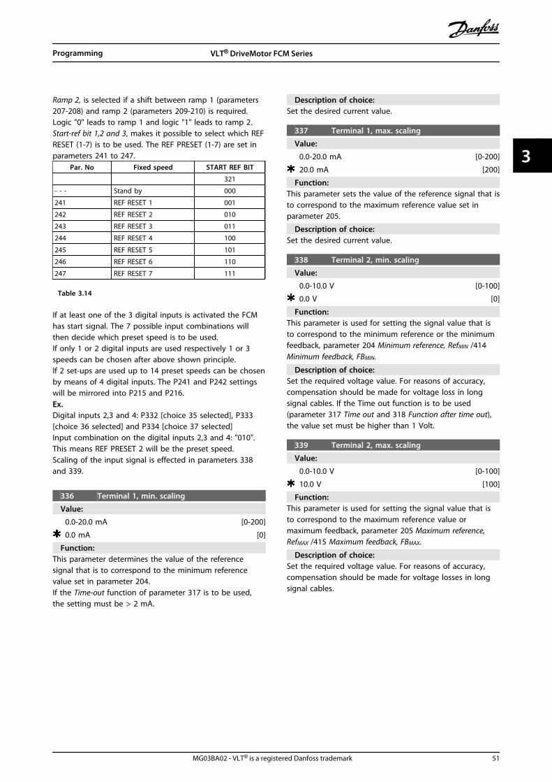
Ramp 2, is selected if a shift between ramp 1 (parameters207-208) and ramp 2 (parameters 209-210) is required.Logic "0" leads to ramp 1 and logic "1" leads to ramp 2.Start-ref bit 1,2 and 3, makes it possible to select which REFRESET (1-7) is to be used. The REF PRESET (1-7) are set inparameters 241 to 247.
Par. No Fixed speed START REF BIT
321
- - - Stand by 000
241 REF RESET 1 001
242 REF RESET 2 010
243 REF RESET 3 011
244 REF RESET 4 100
245 REF RESET 5 101
246 REF RESET 6 110
247 REF RESET 7 111
Table 3.14
If at least one of the 3 digital inputs is activated the FCMhas start signal. The 7 possible input combinations willthen decide which preset speed is to be used.If only 1 or 2 digital inputs are used respectively 1 or 3speeds can be chosen after above shown principle.If 2 set-ups are used up to 14 preset speeds can be chosenby means of 4 digital inputs. The P241 and P242 settingswill be mirrored into P215 and P216.Ex.Digital inputs 2,3 and 4: P332 [choice 35 selected], P333[choice 36 selected] and P334 [choice 37 selected]Input combination on the digital inputs 2,3 and 4: "010".This means REF PRESET 2 will be the preset speed.Scaling of the input signal is effected in parameters 338and 339.
336 Terminal 1, min. scaling
Value:
0.0-20.0 mA [0-200]
0.0 mA [0]
Function:This parameter determines the value of the referencesignal that is to correspond to the minimum referencevalue set in parameter 204.If the Time-out function of parameter 317 is to be used,the setting must be > 2 mA.
Description of choice:Set the desired current value.
337 Terminal 1, max. scaling
Value:
0.0-20.0 mA [0-200]
20.0 mA [200]
Function:This parameter sets the value of the reference signal that isto correspond to the maximum reference value set inparameter 205.
Description of choice:Set the desired current value.
338 Terminal 2, min. scaling
Value:
0.0-10.0 V [0-100]
0.0 V [0]
Function:This parameter is used for setting the signal value that isto correspond to the minimum reference or the minimumfeedback, parameter 204 Minimum reference, RefMIN /414Minimum feedback, FBMIN.
Description of choice:Set the required voltage value. For reasons of accuracy,compensation should be made for voltage loss in longsignal cables. If the Time out function is to be used(parameter 317 Time out and 318 Function after time out),the value set must be higher than 1 Volt.
339 Terminal 2, max. scaling
Value:
0.0-10.0 V [0-100]
10.0 V [100]
Function:This parameter is used for setting the signal value that isto correspond to the maximum reference value ormaximum feedback, parameter 205 Maximum reference,RefMAX /415 Maximum feedback, FBMAX.
Description of choice:Set the required voltage value. For reasons of accuracy,compensation should be made for voltage losses in longsignal cables.
Programming VLT® DriveMotor FCM Series
MG03BA02 - VLT® is a registered Danfoss trademark 51
3 3

Settings:
No function (NO OPERATION) [0]
Ready signal (UNIT READY) [1]
Enable, no warning (ENABLE/NO WARNING) [2]
Running (RUNNING) [3]
Running, no warning (RUNNING NO WARNING) [4]
Running on reference, no warning (RUNNING ON REFERENCE) [5]
Fault (FAULT) [6]
Fault or warning (FAULT OR WARNING) [7]
Current limit (CURRENT LIMIT) [8]
Thermal warning (THERMAL WARNING) [9]
Reversing (REVERSE) [10]
Control word bit 11 (CONTROL WORD BIT 11) [11]
Actual frequency 0-20 mA (0-FMAX = 0-20 mA) [12]
Actual frequency 4-20 mA (0-FMAX = 4-20 mA) [13]
ReferenceMIN - referenceMAX: 0-20 mA (REF MIN-MAX =0-20 mA) [14]
ReferenceMIN - referenceMAX: 4-20 mA (REF MIN-MAX =4-20 mA) [15]
FeedbackMIN - feedbackMAX: 0-20 mA (FB MIN-MAX =0-20 mA) [16]
FeedbackMIN - feedbackMAX: 4-20 mA (FB MIN-MAX =4-20 mA) [17]
Actual current 0-20 mA (0-IMAX = 0-20 mA) [18]
Actual current 4-20 mA (0-IMAX = 4-20 mA) [19]
Mechanical brake (MECHANICAL BRAKE) [20]
Sleep mode (SLEEP MODE) [21]
Torque 0-20 mA (0-TMAX = 0-20 mA) [22]
Torque 4-20 mA (0-TMAX = 4-20 mA) [23]
Table 3.15 340 Terminal 9, Output Functions (OUTPUT FUNC.)
Function:This output can act both as a digital and an analogueoutput. If used as a digital output (data value [0]-[23]), a 24V DC signal is transmitted; if used as an analogue outputeither a 0-20 mA signal, or a 4-20 mA signal output.
Description of choice:Unit Ready signal, the FC motor is ready for use.Enable/no warning, the FC motor is ready for use; no startor stop command has been given (start/ disable). Nowarning.Running, a start command has been given.Running no warning, a start command has been given. Nowarning.Running on reference, no warning, speed according toreference.Fault, output is activated by alarm.Fault or warning, the output is activated by alarm orwarning.Current limit, the current limit in parameter 221 has beenexceeded.Thermal warning, above the temperature limit in thefrequency converter.Reverse. Logic '1' = relay activated, 24 V DC on the outputwhen the direction of rotation of the motor is clockwise.Logic '0' = relay not activated, no signal on the output,when the direction of rotation of the motor is counter-clockwise.
Control word bit 11, if bit 11 = “1” in the control word(both Fieldbus Profile and FC Profile) the digital output willbe activated.0-fMAX (parameter 202) ⇒ 0-20 mA and0-fMAX (parameter 202) ⇒ 4-20 mAReferenceMIN - ReferenceMAX : 0-20 mA andReference MIN - ReferenceMAX: 4-20 mAFeedbackLOW - FeedbackHIGH : 0-20 mA andFeedback LOW - FeedbackHIGH: 4-20 mA0-IVLT, MAX ⇒ 0-20 mA and0-IVLT, MAX ⇒ 4-20 mAMechanical brake, enables control of an optional externalmechanical brake (see also parameter 138 and 139).
Sleep mode, active when the unit is in sleep mode. See3.5.2 Sleep Mode0-TMAX ⇒ 0-20 mA and0-TMAX ⇒ 4-20 mA and3.5.1 Parameter Group 4-** Special
Functions
400 Brake functions
Value:
OFF (OFF) [0]
AC brake (AC BRAKE) [4]
Programming VLT® DriveMotor FCM Series
52 MG03BA02 - VLT® is a registered Danfoss trademark
33

Function:[4] AC brake can be selected to improve braking. With thenew AC brake function it is possible to control the time ofincreased motor losses, still protecting the motorthermally. This function will yield a braking torquebetween 80 and 20% in the speed range up to base speed(50 Hz). Above base speed the extra braking will graduallydisappear.
Illustration 3.21
Description of choice:Select [4] AC brake if short-term generated loads occur.
3.5.2 Sleep Mode
Sleep mode makes it possible to stop the motor when it isrunning at low speed, similar to a no load situation. Ifconsumption in the system goes back up, the frequencyconverter will start the motor and supply the powerrequired.
NOTICEEnergy can be saved with this function, since the motoris only in operation when the system needs it.
Sleep mode is not active if Local reference or Jog has beenselectedThe function is active in both Open loop and Closed loop.
In parameter 403 Sleep mode timer, the Sleep mode isactivated. In parameter 403 Sleep mode timer, a timer is setthat determines how long the output frequency can belower than the frequency set in parameter 404 Sleepfrequency. When the timer runs out, the frequencyconverter will ramp down the motor to stop via parameter208 Ramp-down time. If the output frequency rises above
the frequency set in parameter 404 Sleep frequency, thetimer is reset.
Programming VLT® DriveMotor FCM Series
MG03BA02 - VLT® is a registered Danfoss trademark 53
3 3

While the frequency converter has stopped the motor insleep mode, a theoretical output frequency is calculatedon the basis of the reference signal. When the theoreticaloutput frequency rises above the frequency in parameter407 Wake up frequency, the frequency converter will restartthe motor and the output frequency will ramp up to thereference.
In systems with constant pressure regulation, it isadvantageous to provide extra pressure to the systembefore the frequency converter stops the motor. Thisextends the time during which the frequency converterhas stopped the motor and helps to avoid frequentstarting and stopping of the motor, e.g. in the case ofsystem leaks.If 25% more pressure is required before the frequencyconverter stops the motor, parameter 406 Boost setpoint isset to 125%.Parameter 406 Boost setpoint is only active in Closed loop.
NOTICEIn highly dynamic pumping processes, it isrecommended to switch off the Flying Start function(parameter 445).
Illustration 3.22
403 Sleep mode timer
Value:0 - 300 s (301 s = OFF) OFF
Function:This parameter enables the frequency converter to stopthe motor if the load on the motor is minimal. The timer inparameter 403 Sleep mode timer starts when the outputfrequency drops below the frequency set in parameter 404Sleep frequency.When the time set in the timer has expired, the frequencyconverter will turn off the motor.The frequency converter will restart the motor, when thetheoretical output frequency exceeds the frequency inparameter 407 Wake up frequency.
Description of choice:Select Off if this function is not wanted. Set the thresholdvalue that is to activate Sleep mode after the outputfrequency has fallen below parameter 404 Sleep frequency.
404 Sleep frequency
Value:000,0- par. 407 Wake up frequency 0,0 Hz
Function:When the output frequency falls below the preset value,the timer will start the time count set in parameter 403Sleep mode. The present output frequency will follow thetheoretical output frequency until fMIN is reached.
Description of choice:Set the required frequency.
405 Reset function
Value:
Manual reset (manual RESET) [0]
Automatic reset x 1 (AUTOMATIC X 1) [1]
Automatic reset x 2 (AUTOMATIC X 2) [2]
Automatic reset x 3 (AUTOMATIC X 3) [3]
Automatic reset x 4 (AUTOMATIC X 4) [4]
Automatic reset x 5 (AUTOMATIC X 5) [5]
Automatic reset x 6 (AUTOMATIC X 6) [6]
Automatic reset x 7 (AUTOMATIC X 7) [7]
Automatic reset x 8 (AUTOMATIC X 8) [8]
Automatic reset x 9 (AUTOMATIC X 9) [9]
Automatic reset x 10 (AUTOMATIC X 10) [10]
Reset at power-up (RESET AT POWER UP) [11]
Function:This parameter makes it possible to select the resetfunction desired after tripping.After reset, the FC motor can be restarted after 1.5 s.
Description of choice:If [0] Manual reset is selected, reset must be effected viathe digital inputs.If the FC motor is to carry out an automatic reset (max.1-10 times within 10 minutes) after tripping, select datavalue [1]-[10].
406 Boost setpoint
Value:1 - 200 % 100 % of setpoint
Function:This function can only be used if Closed loop has beenselected in parameter 100.In Systems with constant pressure regulation, it isadvantageous to increase the pressure in the Systembefore the frequency converter stops the motor. Thisextends the time during which the frequency converterstops the motor and helps to avoid frequent starting and
Programming VLT® DriveMotor FCM Series
54 MG03BA02 - VLT® is a registered Danfoss trademark
33

stopping of the motor, e.g. in the case of leaks in thewater supply System.Use Boost Time-Out, par. 472, to set the boost time-out. Ifthe boost set-point cannot be reached within the specifiedtime, the frequency converter will continue in normaloperation (Not entering sleep mode).
Description of choice:Set the required Boost setpoint as a percentage of theresulting reference under normal operation. 100%corresponds to the reference without boost (supplement).
407 Wake up frequency
Value:Par 404 Sleep frequency - par. 202 fMAX 50 Hz
Function:When the theoretical output frequency exceeds the presetvalue, the frequency converter restarts the motor.
Description of choice:Set the required frequency.
411 Switching frequency
Value:
1.5-14.0 kHz [1500-14000]
Unit dependent
Function:The setting determines the switching frequency of theinverter. If the switching frequency is changed, this mayhelp to minimise possible acoustic noise from the motor.
Description of choice:When the motor is running, the switching frequency isadjusted in parameter 411 until the frequency has beenobtained at which the motor is as low-noise as possible.See also parameter 446 - switching pattern. See4.1.6 Thermal Protection and Derating
412 Variable switching frequency
Value:
Not possible (DISABLE) [0]
Variable switching freq. (VAR. CARRIER FREQ.) [1]
Temperature dep. sw. freq. (TEMP. DEP. FREQ.) [2]
Function:This function makes it possible to change the switchingfrequency depending on the load. However, the maximumswitching frequency is determined by the value set inparameter 411.
Description of choice:Select [0] Not possible if a permanent switching frequencyis desired. Set the switching frequency in parameter 411.If [1] Variable switching frequency is selected the switchingfrequency will decline at an increasing output frequency.This is used in applications with square torque character-istics (centrifugal pumps and fans) in which the loaddeclines depending on the output frequency.
If [2] Temperature dependent switching frequency is selected,the switching frequency will decline at an increasinginverter temperature, see Illustration 3.23.
Illustration 3.23
413 Overmodulation function
Value:
Off (OFF) [0]
On (ON) [1]
Function:This parameter allows connection of the overmodulationfunction for the output voltage.
Description of choice:[0] Off means that there is no overmodulation of theoutput voltage, which means that torque ripple on themotor shaft is avoided. This can be a good feature, e.g. ongrinding machines.[1] On means that an output voltage can be obtainedwhich is greater than the mains voltage (up to 5%).
414 Minimum feedback
Value:
-100,000,000 - FB HIGH (par. 415) [-100000000 -]
0.000 [0]
Function:Parameters 414 and 415 are used to scale the feedbackrange to physical values used by the user. The setting willalso be the bounds of the reference (parameters 204 and205).Used together with Process, closed loop mode (parameter100).
Description of choice:Is only active when parameter 203 has been set to [0] Min-Max.
415 Maximum feedback
Value:
(par. 414) FBLOW - 100,000,000 [- 100000000]
Programming VLT® DriveMotor FCM Series
MG03BA02 - VLT® is a registered Danfoss trademark 55
3 3

1.500.000 [1500000]
Function:See description of parameter 414.
416 Reference/feedback unit
Value:
NO UNIT [0]
% [1]
PPM [2]
RPM [3]
bar [4]
CYCLE/min [5]
PULSE/s [6]
UNITS/s [7]
UNITS/min [8]
UNITS/h [9]
°C [10]
Pa [11]
l/s [12]
m3/s [13]
l/min [14]
m3/min [15]
l/h [16]
m3/h [17]
kg/s [18]
kg/min [19]
kg/h [20]
t/min [21]
t/h [22]
m [23]
Nm [24]
m/s [25]
m/min [26]
°F [27]
in wg [28]
gal/s [29]
ft3/s [30]
gal/min [31]
ft3/min [32]
gal/h [33]
ft3/h [34]
lb/s [35]
lb/min [36]
lb/h [37]
lb ft [38]
ft/s [39]
ft/min [40]
Function:Choose among different units to be shown on the display.
This unit is also used directly in Process regulation, closedloop as a unit for Minimum/Maximum reference (parameters204/205) and Minimum/ Maximum feedback (parameters414/415).The possibility of choosing a unit in parameter 416 willdepend on the choices made in the following parameters:Par. 002 Local/remote control.Par. 013 Local control/config. as par. 100.Par. 100 Configuration.Select parameter 002 as Remote controlIf parameter 100 is selected as Speed regulation, open loop,the unit selected in parameter 416 can be used in displays(par. 009-12 Feedback [unit]) of process parameters.Note: The reference can only be shown in Hz (Speedregulation, open loop).If parameter 100 is selected as Process regulation, closedloop, the unit selected in parameter 416 will be used whendisplaying both reference (par. 009- 12: Reference [unit])and feedback (par. 009-12: Feedback [unit]).Select parameter 002 as Local controlIf parameter 013 is chosen as LCP control and open loop orLCP digital control and open loop , the reference will begiven in Hz, regardless of the choice made in parameter416. If parameter 013 is chosen as LCP control/as par. 100or LCP digital control/as par. 100, the unit will be asdescribed above under parameter 002, Remote-control.
Description of choice:Select the desired unit for the reference/feedback signal.
3.5.3 FCM 300 Regulator
Process regulationThe PID regulator maintains a constant process mode(pressure, temperature, flow, etc.) and adjusts the motorspeed on the basis of the reference/setpoint and feedbacksignal.A transmitter provides the PID regulator with a feedbacksignal from the process as an expression of the process'sactual mode. The feedback signal varies as the processload varies.This means that there is a variance between the reference/setpoint and the actual process mode. This variance iscompensated by the PID regulator by means of the outputfrequency being regulated up or down in relation to thevariance between the reference/setpoint and the feedbacksignal.
The integrated PID regulator in the frequency converterhas been optimised for use in process applications. Thismeans that there are a number of special functionsavailable in the frequency converter.Previously it was necessary to obtain a System to handlethese special functions by installing extra I/O modules andprogramming the System. With the frequency converterthe need to install extra modules can be avoided. The
Programming VLT® DriveMotor FCM Series
56 MG03BA02 - VLT® is a registered Danfoss trademark
33

parameters that are specific to the Process Regulator areparameter 437 to parameter 444.
3.5.4 PID Functions
Unit of reference/feedback
When Process regulation, closed loop is selected inparameter 100 Configuration the unit is defined inparameter 416 Reference/feedback unit:
FeedbackA feedback range must be preset for the regulator. At thesame time this feedback range limits the potentialreference range so that if the sum of all references liesoutside the feedback range, the reference will be limitedto lie within the feedback range.The feedback signal must be connected to a terminal onthe frequency converter. If feedback is selected on twoterminals simultaneously, the two signals will be addedtogether.Use the overview below to determine which terminal is tobe used and which parameters are to be programmed.
Feedback type Terminal Parameters
Pulse 3 333, 327
Voltage 2 332, 338, 339
Current 1 331, 336, 337
Table 3.16
A correction can be made for loss of voltage in long signalcables when a transmitter with a voltage output is used.This is done in parameters 338/339 Min./Max scaling.
Parameters 414/415 Minimum/Maximum feedback must alsobe preset to a value in the process unit corresponding tothe minimum and maximum scaling values for signals thatare connected to the terminal.
ReferenceIn parameter 205 Maximum reference, RefMAX it is possibleto preset a maximum reference that scales the sum of allreferences, i.e. the resulting reference.The minimum reference in parameter 204 is an expressionof the minimum value that the resulting reference canassume.All references will be added together and the sum will bethe reference against which regulation will take place. It ispossible to limit the reference range to a range that issmaller than the feedback range. This can be an advantageif you want to avoid an unintentional change to anexternal reference making the sum of the references movetoo far away from the optimal reference. The referencerange cannot exceed the feedback range.
If preset references are desired, they are preset inparameters 215 to 216 Preset reference. See descriptionReference Function and Handling of References in parameter214.If a current signal is used as the feedback signal, it willonly be possible to use voltage as an analogue reference.Use the overview below to determine which terminal is tobe used and which parameters are to be programmed.
Reference type Terminal Parameters
Pulse 3 333, 327
Voltage 2 332, 338, 339
Current 1 331, 336, 337
Presetreferences
215-216(241-247)
Bus reference 68+69
Table 3.17
NOTICEThe bus reference can only be presetvia serial communication.
NOTICEIt is best to preset terminals that are notbeing used to [0] No function.
Differentiator gain limitIf very rapid variations occur in an application in either thereference signal or the feedback signal, the deviationbetween the reference/setpoint and the process's actualmode will change quickly. The differentiator can thenbecome too dominant. This is because it is reacting to thedeviation between the reference and the process's actualmode, and the quicker the variance changes the morepowerful the differentiator's frequency contributionbecomes. The differentiator's frequency contribution cantherefore be limited in such a way that both a reasonabledifferentiation time for slow changes and an appropriatefrequency contribution for quick changes can be preset.This is done using parameter 443 Process PID Differentiatorgain limit.
Lowpass filterIf there is a lot of noise in the feedback signal, these canbe dampened using an integrated lowpass filter. A suitablelowpass filter time constant is preset.If the lowpass filter is preset to 0.1 s, the cut-off frequencywill be 10 RAD/sec, corresponding to (10 / 2 x π) = 1.6 Hz.This will mean that all currents/voltages that vary by morethan 1.6 oscillations per second will be dampened. In otherwords, there will only be regulation on the basis of afeedback signal that varies by a frequency of less than 1.6Hz. The appropriate time constant is selected in parameter444 Process PID lowpass filter time.
Programming VLT® DriveMotor FCM Series
MG03BA02 - VLT® is a registered Danfoss trademark 57
3 3

Inverse regulationNormal regulation means that the motor speed isincreased when the reference/setpoint is greater than thefeedback signal. If it is necessary to run inverse regulation,in which the speed is reduced when the reference/setpointis greater than the feedback signal, parameter 437 PIDnormal/inverse control must be programmed at Inverted .
Anti WindupIn the factory the process regulator is preset with an activeanti windup function. This function means that wheneither a frequency limit, a current limit or a voltage limit isreached, the integrator is initialised at a frequencycorresponding to the present output frequency. This is ameans of avoiding the integration of a variance betweenthe reference and the process's actual mode that cannotbe deregulated by means of a change of speed. Thisfunction can be deselected in parameter 438 Process PIDanti windup.
Starting conditionsIn some applications the optimal setting of the processregulator will mean that a relatively long period of timewill pass before the required process condition is achieved.In these applications it can be a good idea to define anoutput frequency to which the frequency converter mustrun the motor before the process regulator is activated.This is done by programming a start frequency inparameter 439 Process PID start frequency.
3.5.5 Handling of Feedback
Feedback handling is depicted in this flowchart.The flowchart shows which parameters can affect thehandling of feedback and how. A choice can be madebetween voltage, current and pulse feedback signals.
Illustration 3.24
437 Process PID Normal/inverse control
Value:
Normal (NORMAL) [0]
Inverse (INVERSE) [1]
Function:It is possible to choose whether the process regulator is toincrease/reduce the output frequency if there is a
difference between the reference signal and the feedbacksignal.Used together with Process, closed loop mode (parameter100).
Description of choice:If the FC motor is to reduce the output frequency in casethe feedback signal increases, select [0] Normal. If the FCmotor is to increase the output frequency in case thefeedback signal increases, select [1] Inverse.
438 Process PID anti windup
Value:
Disable (DISABLE) [0]
Enable (ENABLE) [1]
Function:It is possible to select whether the process regulator is tocontinue regulating on an error even if it is not possible toincrease/reduce the output frequency. Used together withProcess, closed loop mode (parameter 100).
Description of choice:The factory setting is [1] Enable, which means that theintegration link is adjusted in relation to the actual outputfrequency if either the current limit or the max./ min.frequency has been reached. The process regulator will notengage again until either the error is zero or its sign haschanged.Select [0] Disable if the integrator is to continue integratingon an error, even if it is not possible to remove the faultby such regulation.
439 Process PID start frequency
Value:
fMIN-fMAX (parameter 201 and 202) [X.X]
parameter 201
Function:When the start signal comes, the FC motor will react in theform of Speed, open loop mode following the ramp. Onlywhen the programmed start frequency has been obtained,will it change over to Process, closed loop mode. Inaddition, it is possible to set a frequency that correspondsto the speed at which the process normally runs, whichwill enable the required process conditions to be reachedsooner.Used together with Process, closed loop mode (parameter100).
Description of choice:Set the required start frequency.
440 Process PID proportional gain
Value:
0.00 (OFF)-10.00 [0-1000]
0.01 [1]
Programming VLT® DriveMotor FCM Series
58 MG03BA02 - VLT® is a registered Danfoss trademark
33
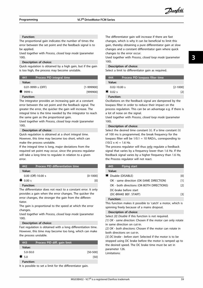
Function:The proportional gain indicates the number of times theerror between the set point and the feedback signal is tobe applied.Used together with Process, closed loop mode (parameter100).
Description of choice:Quick regulation is obtained by a high gain, but if the gainis too high, the process may become unstable.
441 Process PID integral time
Value:
0.01-9999 s (OFF) [1-999900]
9999 s [999900]
Function:The integrator provides an increasing gain at a constanterror between the set point and the feedback signal. Thegreater the error, the quicker the gain will increase. Theintegral time is the time needed by the integrator to reachthe same gain as the proportional gain.Used together with Process, closed loop mode (parameter100).
Description of choice:Quick regulation is obtained at a short integral time.However, this time may become too short, which canmake the process unstable.If the integral time is long, major deviations from therequired set point may occur, since the process regulatorwill take a long time to regulate in relation to a givenerror.
442 Process PID differentiation time
Value:
0.00 (Off)-10.00 s [0-1000]
0.00 s [0]
Function:The differentiator does not react to a constant error. It onlyprovides a gain when the error changes. The quicker theerror changes, the stronger the gain from the differen-tiator.The gain is proportional to the speed at which the errorchanges.Used together with Process, closed loop mode (parameter100).
Description of choice:Fast regulation is obtained with a long differentiation time.However, this time may become too long, which can makethe process unstable.
443 Process PID diff. gain limit
Value:
5.0-50.0 [50-500]
5.0 [50]
Function:It is possible to set a limit for the differentiator gain.
The differentiator gain will increase if there are fastchanges, which is why it can be beneficial to limit thisgain, thereby obtaining a pure differentiator gain at slowchanges and a constant differentiator gain where quickchanges to the error occur.Used together with Process, closed loop mode (parameter100).
Description of choice:Select a limit to differentiator gain as required.
444 Process PID lowpass filter time
Value:
0.02-10.00 s [2-1000]
0.02 s [2]
Function:Oscillations on the feedback signal are dampened by thelowpass filter in order to reduce their impact on theprocess regulation. This can be an advantage e.g. if there isa lot of noise on the signal.Used together with Process, closed loop mode (parameter100).
Description of choice:Select the desired time constant (τ). If a time constant (τ)of 100 ms is programmed, the break frequency for thelowpass filter will be 1/0.1 = 10 RAD/s., corresponding to(10/2 x π) = 1.6 Hz.The process regulator will thus only regulate a feedbacksignal that varies by a frequency lower than 1.6 Hz. If thefeedback signal varies by a higher frequency than 1.6 Hz,the Process regulator will not react.
445 Flying start
Value:
Disable (DISABLE) [0]
OK - same direction (OK-SAME DIRECTION) [1]
OK - both directions (OK-BOTH DIRECTIONS) [2]
DC-brake before start(DC-BRAKE BEF. START) [3]
Function:This function makes it possible to ‘catch‘ a motor, which isspinning freely because of a mains dropout.
Description of choice:Select [0] Disable if this function is not required.[1 OK - same direction: Chosen if the motor can only rotatein same direction on cut-in.[2] OK - both directions: Chosen if the motor can rotate inboth directions on cut-in.[3] DC-brake - before start: Selected if the motor is to bestopped using DC brake before the motor is ramped up tothe desired speed. The DC brake time must be set inparameter 126.Limitations:
Programming VLT® DriveMotor FCM Series
MG03BA02 - VLT® is a registered Danfoss trademark 59
3 3
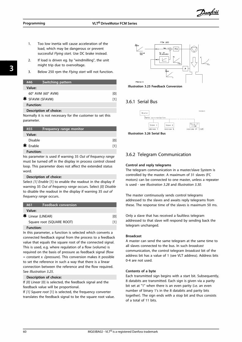
1. Too low inertia will cause acceleration of theload, which may be dangerous or preventsuccessful Flying start. Use DC brake instead.
2. If load is driven eg. by "windmilling", the unitmight trip due to overvoltage.
3. Below 250 rpm the Flying start will not function.
446 Switching pattern
Value:
60° AVM (60° AVM) [0]
SFAVM (SFAVM) [1]
Function:
Description of choice:Normally it is not necessary for the customer to set thisparameter.
455 Frequency range monitor
Value:
Disable [0]
Enable [1]
Function:his parameter is used if warning 35 Out of frequency rangemust be turned off in the display in process control closedloop. This parameter does not affect the extended statusword.
Description of choice:Select [1] Enable [1] to enable the readout in the display ifwarning 35 Out of frequency range occurs. Select [0] Disableto disable the readout in the display if warning 35 out offrequency range occurs.
461 Feedback conversion
Value:
Linear (LINEAR) [0]
Square root (SQUARE ROOT) [1]
Function:In this parameter, a function is selected which converts aconnected feedback signal from the process to a feedbackvalue that equals the square root of the connected signal.This is used, e.g. where regulation of a flow (volume) isrequired on the basis of pressure as feedback signal (flow= constant x √pressure). This conversion makes it possibleto set the reference in such a way that there is a linearconnection between the reference and the flow required.See Illustration 3.25.
Description of choice:If [0] Linear [0] is selected, the feedback signal and thefeedback value will be proportional.If [1] Square root [1] is selected, the frequency convertertranslates the feedback signal to be the square root value.
Illustration 3.25 Feedback Conversion
3.6.1 Serial Bus
Illustration 3.26 Serial Bus
3.6.2 Telegram Communication
Control and reply telegramsThe telegram communication in a master/slave System iscontrolled by the master. A maximum of 31 slaves (FCmotors) can be connected to one master, unless a repeateris used - see Illustration 3.28 and Illustration 3.30.
The master continuously sends control telegramsaddressed to the slaves and awaits reply telegrams fromthese. The response time of the slaves is maximum 50 ms.
Only a slave that has received a faultless telegramaddressed to that slave will respond by sending back thetelegram unchanged.
BroadcastA master can send the same telegram at the same time toall slaves connected to the bus. In such broadcastcommunication, the control telegram broadcast bit of theaddress bit has a value of 1 (see VLT address). Address bits0-4 are not used.
Contents of a byteEach transmitted sign begins with a start bit. Subsequently,8 databits are transmitted. Each sign is given via a paritybit set at "1" when there is an even parity (i.e. an evennumber of binary 1's in the 8 databits and parity bitstogether). The sign ends with a stop bit and thus consistsof a total of 11 bits.
Programming VLT® DriveMotor FCM Series
60 MG03BA02 - VLT® is a registered Danfoss trademark
33

0 1 32 4 5 6 7
195N
A03
6.10
Startbit
Even StopParity bit
Illustration 3.27
3.6.3 Telegram Build-up
Each telegram begins with a startbyte (STX) = 02 Hex,followed by a byte that gives the telegram length (LGE)and a byte that gives the address (ADR). Then follows anumber of databytes (variable, depending on telegramtype). The telegram ends with a data control byte (BCC).
STX LGE ADR DATA BCC
195N
A09
9.10
Illustration 3.28 Telegram
Telegram length (LGE)The telegram length is the number of databytes plusaddress byte ADR plus data control byte BCC.
Telegrams with 4 databytes have a length of:LGE = 4 + 1 + 1 = 6 bytesTelegrams with 12 databytes have a length of:LGE = 12 + 1 + 1 = 14 bytes
VLT address (ADR)Two different address formats are used:
1. Siemens USS protocol address format:
Illustration 3.29 Address Format
Bit 7 = 0Bit 6 is not usedBit 5 = 1: Broadcast, address bits (0-4) are not usedBit 5 = 0: No BroadcastBits 0-4 = VLT address 1-31
2. Danfoss format:
Illustration 3.30 Address Format
Bit 7 = 1Bits 0-6 = VLT address 1-127 (0 = Broadcast)
Data control byte (BCC)The data control byte can best be explained by means ofan example: Before the first sign of the telegram isreceived, BCC = 0.
Illustration 3.31
After the first sign has been received:BCCNEW = BCCOLD EXOR "first byte"(EXOR = exclusive-or gate)BCC OLD = 0 0 0 0 0 0 0 0EXOR"first byte" = 0 0 0 0 0 0 1 0 (02H)BCCNEW = 0 0 0 0 0 0 1 0Each additional, subsequent byte is gated byBCC OLD EXOR and gives a new BCCNEW, e.g.:
BCCOLD= 0 0 0 0 0 0 1 0EXOR"second byte" = 1 1 0 1 0 1 1 0 (D6H)BCCNEW = 1 1 0 1 0 1 0 0
The result after the last received sign is BCC.
3.6.4 Databytes
The block of databytes is divided into two smaller blocks:
1. Parameter bytes used for transferred parametersbetween master and slave
2. Process bytes, covering
- Control word and reference value (frommaster to slave)
- Status word and present outputfrequency (from slave to master)
This structure applies to both the control telegram (master⇒ slave) and the reply telegram (slave ⇒master).
Illustration 3.32
There are two types of telegrams:
Programming VLT® DriveMotor FCM Series
MG03BA02 - VLT® is a registered Danfoss trademark 61
3 3

- with 12 bytes built up as shown above, withparameter and process block
- with four bytes, which is the process block fromthe 12 byte telegram
1. Parameter bytes
Illustration 3.33
Commands and replies (AK)Bits no. 12-15 are used for transmitting commands frommaster to slave and the slave's processed reply back to themaster.
Commands master ⇒slave:Bit no.
15 14 13 12 Command
0 0 0 0 No command
0 0 0 1 Read parameter value
0 0 1 0 Write parameter value in RAM(word)
0 0 1 1 Write parameter value in RAM(double word)
1 1 0 1 Write parameter value in RAM andEEPROM (double word)
1 1 1 0 Write parameter value in RAM andEEPROM (word)
1 1 1 1 Read text
Table 3.18
Reply slave ⇒ master:Bit no.
15 14 13 12 Reply
0 0 0 0 No reply
0 0 0 1 Parameter value transferred (word)
0 0 1 0 Parameter value transferred(double word)
0 1 1 1 Command cannot be executed
1 1 1 1 Text transferred
Table 3.19
If the command cannot be executed, the slave will sendthis reply (0111) and give the following error message inthe parameter value:
Error code
(reply 0111) Error message
0 The parameter number used does not exist
1 There is no write access to the parameter called
2 The data value exceeds the parameter limits
3 The used sub-index does not exist
4 The parameter is not of the array type
5 The data type does not match the parametercalled
17 Data change in the parameter called is notpossible in the present mode of the FC motor.E.g. some parameters can only be changedwhen the motor has stopped
130 There is no bus access to the parameter called
131 Data change is not possible because factorySetup has been selected
Table 3.20
Parameter number (PNU)Bits no. 0-10 are used for transmitting parameter numbers.The function of a given parameter can be seen from theparameter description.
Illustration 3.34
IndexIndex is used together with the parameter number forread/write access to parameters of the array type (par. 615,616 and 617).
Parameter value (PWE)
Programming VLT® DriveMotor FCM Series
62 MG03BA02 - VLT® is a registered Danfoss trademark
33

Illustration 3.35
The parameter value depends on the command given. Ifthe master wants a parameter (read), it does not careabout the PWE block value. If a parameter is changed bythe master (write), the new value is transferred in the PWEblock. If the slave replies to a parameter request (readcommand), the present parameter value is transferred tothe PWE block.
The transferred value corresponds to the figures given inthe parameter description. E.g. parameter 101, where [1]corresponds to Constant torque, [2] corresponds to Variabletorque: low, etc. However, parameters with data type 9(text string) are excepted, as this text is transferred as anASCII text string. When a text string is transferred (read),the telegram length is variable, since the texts havedifferent lengths. The telegram length is stated in the 2ndbyte of the telegram, called LGE, see 3.6.3 Telegram Build-up . Parameters 621-634 (nameplate data) have data type 9(text string).
Data Types Supported by the VLT Frequency Converter
Data type Description
3 Integer 16
4 Integer 32
5 Unsigned 8
6 Unsigned 16
7 Unsigned 32
9 Text string
Table 3.21
Unsigned means there is no sign included in the telegram.
The different attributes for each parameter can be seen inthe section on factory settings. Since a parameter valuecan only be transferred as an integer, a conversion factormust be used to transfer decimals.
Example:Parameter 201: minimum frequency, conversion factor 0,1.If parameter 201 is to be set to 10 Hz, a value of 100 mustbe transferred, since a conversion factor of 0,1 means thatthe transferred value will be multiplied by 0.1. A value of100 will thus be understood as 10.
Addressing by unit ID
The unit ID is printed on the label on the plastic coverunder the lid of the electronics box. The three groups ofunit ID each with three digits must be converted to Hex.The desired address is added as the last byte. The frame issent to the bus address parameter(s) 500 (and 918) via abroadcast.
PKE: Write to parameter No. 500 or 918IND: Not Used
2. Process-bytesThe process byte block is divided into two blocks each of16 bits, which always come in the sequence stated.
Illustration 3.36
PCD1 PCD2
Control telegram
(master⇒slave)
Control word Reference value
Reply telegram
(slave⇒master)
Status word Given outputfrequency
Table 3.22
3.6.5 Control Word According to FieldbusProfile Standard
(parameter 512 = Fieldbus Profile) The control word isused for transmitting commands from a master (e.g. a PC)to a slave (FC motor).
Programming VLT® DriveMotor FCM Series
MG03BA02 - VLT® is a registered Danfoss trademark 63
3 3

Bit Bit = 0 Bit =1
00 OFF 1 ON 1
01 OFF 2 ON 2
02 OFF 3 ON 3
03 Motor coasting Enable
04 Quick-stop Ramp
05 Freeze output frequency Ramp enable
06 Ramp stop Start
07 No function Reset
08 Jog 1 OFF ON
09 Jog 2 OFF ON
10 Data not valid Valid
11 No function Slow down/Relay 123/Digital output terminal9
12 No function Catch-up/Relay 123
13 Setup 1 Setup 2
14
15 No function Reversing
Table 3.23
NOTICEThe use of Bit 00, Bit 01 and Bit 02 for switching off thepower supply (by use of relay) will require a separatepower on. This because there is no 24 #V externalconnection to supply the FCM 300 control, which isrequired to activate the FCM 300 again via input signal.
Bit 00, OFF1/ON1An ordinary ramp stop which uses the ramp time inparameters 207/208. Bit 00 = "0" leads to a stop. Bit 00 =“1” means that the frequency converter will be able tostart if the other conditions for starting have been fulfilled.
Bit 01, OFF2/ON2Coasting stop. Bit 01 = "0" leads to a coasting stop. Bit 01= "1" means that the frequency converter is able to start,provided the other conditions for starting have beenfulfilled.
Bit 02, OFF3/ON3Quick-stop, which uses the ramp time in parameter 212.Bit 02 = "0" leads to a quick-stop. Bit 02 = "1" means thatthe frequency converter is able to start, provided the otherconditions for starting have been fulfilled.
Bit 03, Coasting/enable
Coasting. Bit 03 = "0" leads to a stop. Bit 03 = "1" meansthat the frequency converter is able to start, provided theother conditions for starting are fulfilled.
NOTICEIn parameter 502 the choice is made as to how bit 03 isto be combined (gated) with the corresponding functionin the digital inputs.
Bit 04, Quick-stop/rampQuick-stop which uses the ramp time in parameter 212. Bit04 = "0" leads to a quick-stop. Bit 04 = "1" means that thefrequency converter is able to start, provided the otherconditions for starting are fulfilled.
NOTICEIn parameter 503 the choice is made as to how bit 04 isto be combined (gated) with the corresponding functionon the digital inputs.
Bit 05, Freeze output frequency/ramp enableBit 05 = "0" means that the given output frequency ismaintained even if the reference is changed. Bit 05 = "1"means that the frequency converter is again able toregulate, and the given reference is followed.
Bit 06, Ramp stop/startAn ordinary ramp stop that uses the ramp time inparameters 207/208. Bit 06 = "0" leads to a stop. Bit 06 ="1" means that the frequency converter is able to start,provided the other conditions for starting have beenfulfilled.
NOTICEIn parameter 505 the choice is made as to how bit 06 isto be combined (gated) with the corresponding functionon the digital inputs.
Bit 07, No function/resetReset of trip. Bit 07 = "0" means that there is no reset. Bit07 = "1" means that a trip is reset. After reset it will takeapprox. 1.5 second until the unit is ready. The status wordwill indicate the ready state.
Bit 08, Jog 1 OFF/ONActivation of pre-programmed speed in parameter 509(Bus JOG 1). JOG 1 is only possible when Bit 04 = "0" andbit 00-03 = "1".
Bit 09, Jog 2 OFF/ONActivation of pre-programmed speed in parameter 510(Bus JOG 2). JOG 2 is only possible when Bit 04 = "0" andBits 00-03 = "1". If both JOG 1 and JOG 2 are activated(Bits 08 and 09 = "1"), JOG 1 has the higher priority, which
Programming VLT® DriveMotor FCM Series
64 MG03BA02 - VLT® is a registered Danfoss trademark
33

means that the speed programmed in parameter 509 willbe used.
Bit 10, Data not valid/validUsed for telling the FC motor whether the control word isto be used or ignored. Bit 10 = "0" means that the controlword is ignored. Bit 10 = "1" means that the control wordis used. This function is relevant because the control wordis always contained in the telegram, regardless of the typeof telegram used, i.e. it is possible to disconnect thecontrol word if it is not to be used in connection withupdating or reading of parameters.
Bit 11, No function/slow down, relay 123, digital outputterminal 9Used for reducing the speed reference by the value inparameter 219. Bit 11 = "0" means that there is no changeof the reference. Bit 11 = "1" means that the reference isreduced. Bit 11 = “1” will also activate relay 123 (providedparameter 323 = “Control word bit 11”) and set digital outterminal 9 high (provided parameter 340 = “Control wordbit 11”).
Bit 12, No function/catchup, relay 123Used for increasing the speed reference by the value ofparameter 219. Bit 12 = "0" means that there is no changeof the reference; Bit 12 = "1" means that the reference isincreased. If both slow down and catchup are activated(Bits 11 and 12 = "1"), slow down has the higher priority,i.e. the speed reference is reduced. Bit 12 = “1” will alsoactivate relay 123 (provided parameter 323 = “Controlword bit 12”).
Bits 13, Choice of SetupBit 13 is used for choosing between the two menu Setupsin accordance with the following table:
Setup Bit 13
1 0
2 1
Table 3.24
This function is only possible if Multi-Setups have beenselected in parameter 004.
NOTICEParameter 507 is used for choosing how Bit 13 is to becombined (gated) with the corresponding function onthe digital inputs.
Bit 15, No function/reversingReversing of the direction of rotation of the motor. Bit 15= "0" leads to no reversing, Bit 15 = "1" leads to reversing.
NOTICEUnless otherwise mentioned, the control word bit iscombined (gated) with the corresponding function onthe digital inputs as a logic "or" function.
Status word (according to Fieldbus Profile standard)The status word is used for informing the master (e.g. aPC) of the condition of a slave (FC motor).
Bit Bit = 0 Bit =1
00 Control not ready Ready
01 FC not ready Ready
02 Coasting Enable
03 No fault Trip
04 ON 2 OFF 2
05 ON 3 OFF 3
06 Start enable Start disable
07 No warning Warning
08 Speed ≠ ref. Speed = ref.
09 Local control Serial communication
10 Outside frequency range Frequency limit OK
11 Not running Running
12
13 Voltage OK Above limit
14 Current OK Above limit
15 Thermal warning
Table 3.25
Bit 00, Control not ready/readyBit 00 = "0" means that bit 00, 01 or 02 of the controlword is "0" (OFF1, OFF2 or OFF3), or that the frequencyconverter has tripped.Bit 00 = "1" means that the frequency converter control isready.
Programming VLT® DriveMotor FCM Series
MG03BA02 - VLT® is a registered Danfoss trademark 65
3 3
Bit 01, FC not ready/readySame meaning as bit 00; however, there is also a supply tothe power section, and the frequency converter is ready torun when it receives the necessary start signals.
Bit 02, Coasting/enableBit 02 = "0" means that the control word bit 00, 01, 02 or03 is "0" (OFF1, OFF2, OFF3 or Coasting), or the FCM 300Series unit has tripped.Bit 02 = "1" means that the control word bits 00, 01, 02 or03 are "1" and that the FC motor has not tripped.
Bit 03, No fault/tripBit 03 = "0" means that FCM 300 Series is not in a faultcondition.Bit 03 = "1" means that FCM 300 Series has tripped andneeds a reset signal in order to run.
Bit 04, ON2/OFF2Bit 04 = "0" means that control word bit 01 = "1".Bit 04 = "1" means that control word bit 01 = "0".
Bit 05, ON3/OFF3Bit 05 = "0" means that control word bit 02 = "1".Bit 05 = "1" means that control word bit 02 = "0".
Bit 06, Start enable/start disableBit 06 is always "0" if FC Drive has been selected inparameter 512. If [Profidrive] has been selected inparameter 512, bit 06 will be "1" after reset of a trip, afteractivation of OFF2 or OFF3 and after connection of mainsvoltage. Start disable is reset, setting control word bit 00to "0" and bits 01, 02 and 10 to "1".
Bit 07, No warning/warningBit 07 = "0" means that there is no unusual situation.Bit 07 = "1" means that an abnormal condition has arisenfor the FC motor. All warnings described in 4.2 List ofWarnings and Alarms - FCM 300 Design Guide will set bit 07to "1".
Bit 08, Speed ≠ ref/speed. = ref.Bit 08 = "0" means that the actual motor speed is differentfrom the speed reference set. This can be the case i.a.while the speed is ramped up/down during start/stop.Bit 08 = "1" means that the present motor speed equalsthe speed reference set.
Bit 09, Local operation/serial communication controlBit 09 = "0" means that [STOP/RESET] is activated on thecontrol unit, or that Local control in parameter 002 Local/remote operation is selected. It is not possible to controlthe frequency converter via serial communication.Bit 09 = “1” means that it is possible to control thefrequency converter via serial communication.
Bit 10, Outside frequency rangeBit 10 = "0", if the output frequency has reached the valuein parameter 201 Output frequency low limit or parameter202 Output frequency high limit.Bit 10 = “1” means that the output frequency is within thedefined limits.
Bit 11, Not running/runningBit 11 = "0" means that the motor is not running.Bit 11 = "1" means that the FC motor has a start signal orthat the output frequency is greater than 0 Hz.
Bit 13, Voltage OK/above limitBit 13 = "0" means that the voltage limits of the FC motorhave not been exceeded.Bit 13 = "1" means that the DC voltage of the FC motorintermediate circuit is too low or too high.
Bit 14, Current OK/above limitBit 14 = "0" means that the motor current is lower thanthe current limit selected in parameter 221.Bit 14 = "1" means that the current limit in parameter 221has been exceeded.
Bit 15, Thermal warningBit 15 = "0" means that the timers for motor thermalprotection and VLT thermal protection, respectively, havenot exceeded 100%.Bit 15 = "1" means that one of the timers has exceeded100%.
Control word under FC Profile (parameter 512 = FCDrive)The control word is used for sending commands from amaster (e.g. a PC) to a slave (FC motor).
Programming VLT® DriveMotor FCM Series
66 MG03BA02 - VLT® is a registered Danfoss trademark
33

Bit Bit = 0 Bit =1
00 Preset reference choice
01 No function
02 DC brake Ramp
03 Coasting Enable
04 Quick-stop Ramp
05 Hold Ramp enable
06 Ramp stop Start
07 No function Reset
08 No function Jog
09 No function
10 Data not valid Valid
11 No function Relay 123 / digitalinput terminal 9
12 No function Relay 123
13 Setup 1 Setup 2
15 No function Reversing
Table 3.26
Bit 00Bit 00 is used for choosing between the two pre-programmed references (parameters 215-216) inaccordance with the following table:
Preset ref. Parameter Bit 00
1 215 0
2 216 1
Table 3.27
NOTICEParameter 508 is where to choose the way bits 1/12 areto be combined (gated) with the corresponding functionon the digital inputs.
Bit 02, DC brakeBit 02 = "0" leads to DC braking and stop. Braking currentand duration are set in parameters 132 and 133.Bit 02 = "1" leads to ramp.
Bit 03, Coasting/enableCoasting. Bit 03 = "0" leads to a stop.Bit 03 = "1" means that the frequency converter is able tostart, provided the other conditions for starting have beenfulfilled.
NOTICEIn parameter 502 the choice is made as to how bit 03 isto be combined (gated) with the corresponding functionin the digital inputs.
Bit 04, Quick-stop/rampQuick-stop which uses the ramp time in parameter 212. Bit04 = “0” leads to a quick-stop.Bit 04 = “1” means that the frequency converter is able tostart, provided the other conditions for starting have beenfulfilled.
NOTICEIn parameter 503 the choice is made as to how bit 04 isto be combined (gated) with the corresponding functionon the digital inputs.
Bit 05, Hold/ramp enableBit 05 = “0” means that the given output frequency ismaintained even if the reference is changed.Bit 05 = “1” means that the frequency converter is againable to regulate, and the given reference is followed.
Bit 06, Ramp stop/startAn ordinary ramp stop that uses the ramp time inparameters 207/208. Bit 06 = “0” leads to a stop.Bit 06 = “1” means that the frequency converter is able tostart, provided the other conditions for starting have beenfulfilled.
NOTICEIn parameter 505 the choice is made as to how bit 06 isto be combined (gated) with the corresponding functionon the digital inputs.
Bit 07, No function/resetReset of trip. Bit 07 = “0” means that there is no reset.Bit 07 = “1” means that a trip is reset. After reset it willtake approx. 1.5 second until the unit is ready. The statusword will indicate the ready state.
Bit 08, Activation of Jog speed in parameter 213Bit 08 = "0": Jog speed not activated.Bit 08 = "1" means that the motor is running at Jog speed.
Bit 10, Data not valid/validUsed for telling the FC motor whether the control word isto be used or ignored.Bit 10 = “0” means that the control word is ignored.Bit 10 = “1” means that the control word is used. Thisfunction is relevant because the control word is alwayscontained in the telegram, regardless of the type oftelegram used, i.e. it is possible to disconnect the controlword if it is not to be used in connection with updating orreading of parameters.
Programming VLT® DriveMotor FCM Series
MG03BA02 - VLT® is a registered Danfoss trademark 67
3 3

Bit 11, No function/relay 123, digital output terminal 9Bit 11 = “1” will activate relay 123 (provided parameter 323= “Control word bit 11”) and set digital out terminal 9 high(provided parameter 340 = “Control word bit 11”).
Bit 12, No function/relay 123Bit 12 = “1” will activate relay 123 (provided parameter 323= “Control word bit 12”).
Bit 13, Choice of set-upBit 13 is used for choosing between the two menu set-upsin accordance with the following table:
Setup Bit 13
1 0
2 1
Table 3.28
This function is only possible if Multi-Set-ups have beenselected in parameter 004.
NOTICEParameter 507 is used for choosing how Bit 13 is to becombined (gated) with the corresponding function onthe digital inputs.
Bit 15, No function/reversingReversing of the direction of rotation of the motor.Bit 15 = “0” leads to no reversing. Bit 15 = “1” leads toreversing.
NOTICEUnless otherwise mentioned, the control word bit iscombined (gated) with the corresponding function onthe digital inputs as a logic "or" function.
Status word under FC ProfileThe status word is used for informing the master (e.g. a PC)about the condition of the slave (FC motor).
Bit Bit = 0 Bit =1
00 Control not ready Ready
01 FC not ready Ready
02 Coasting Enable
03 No fault Trip
04 Reserved
05 Reserved
06 Reserved
07 No warning Warning
08 Speed ≠ ref. Speed = ref.
09 Local control Bus control
10 Out of range Frequency OK
11 Not running Running
12
13 Voltage OK Above limit
14 Current OK Above limit
15 Timer OK Thermal warning
Table 3.29
Bit 01, FC not ready/readyBit 01 = "0" means that the frequency converter hastripped.Bit 01 = "1" means that the frequency converter is ready.
Bit 02, Coasting/enableBit 02 = "0" means that the control word bit 03 is "0"(Coasting) or that the FC motor has tripped.Bit 02 = "1" means that control word bit 03 is "1" and thatthe FC motor has not tripped.
Bit 03, No fault/tripBit 03 = "0" means that FCM 300 Series is not in a faultcondition.Bit 03 = “1” means that FCM 300 Series has tripped andneeds a reset signal in order to run.
Bit 07, No warning/warningBit 07 = "0" means that there is no unusual situation.Bit 07 = “1” means that an abnormal condition has arisenfor the FC motor. All warnings described in4.2 List ofWarnings and Alarms - FCM 300 Design Guide will set bit 07to “1”.
Bit 08, Speed ≠ ref/speed. = ref.
Programming VLT® DriveMotor FCM Series
68 MG03BA02 - VLT® is a registered Danfoss trademark
33

Bit 08 = "0" means that the actual motor speed is differentfrom the speed reference set. This can be the case i.e.while the speed is ramped up/down during start/stop.Bit 08 = “1” means that the present motor speed equalsthe speed reference set.
Bit 09, Local operation / bus controlBit 09 = "0" means that [STOP/RESET] is activated on thecontrol unit, or that Local control in parameter 002 Local/remote operation is selected. It is not possible to controlthe frequency converter via serial communication.Bit 09 = “1” means that it is possible to control thefrequency converter via serial communication.
Bit 10, Out of range/frequencyBit 10 = "0", if the output frequency has reached the valuein parameter 201 Output frequency low limit or parameter202 Output frequency high limit.Bit 10 = “1” means that the output frequency is within thedefined limits.
Bit 11, Not running/runningBit 11 = "0" means that the motor is not running.Bit 11 = “1” means that the FC motor has a start signal orthat the output frequency is greater than 0 Hz.
Bit 13, Voltage OK/above limitBit 13 = "0" means that the voltage limits of the FC motorhave not been exceeded.Bit 13 = "1" means that the DC voltage of the FC motorintermediate circuit is too low or too high.
Bit 14, Current OK/above limitBit 14 = "0" means that the motor current is lower thanthe torque limit selected in parameter 221.Bit 14 = "1" means that the torque limit in parameter 221has been exceeded.
Bit 15, Thermal warningBit 15 = "0" means that the timers for motor thermalprotection and VLT thermal protection, respectively, havenot exceeded 100%.Bit 15 = "1" means that one of the timers has exceeded100%.
Bus reference value
Illustration 3.37
The frequency reference value is transmitted to thefrequency converter in the form of a 16-bit word. Thevalue is transmitted as a whole number (0-32767). 16384(4000 Hex) corresponds to 100%. (Negative figures areformed by means of 2's complement.)
The bus reference has the following format:Parameter 203 = "0""refMIN-refMAX"0-16384 (4000 Hex) ~ 0-100% ~ refMIN - refMAX
Parameter 203 = "1"-refMAX - +refMAX
-16384 (. . . Hex) - +16384 (4000 Hex) ~-100- +100% ~ -refMAX- +refMAX
Actual output frequency
Illustration 3.38
The value of the actual output frequency of the frequencyconverter is transmitted in the form of a 16- bit word. Thevalue is transmitted as a whole number (0-32767). 16384(4000 Hex) corresponds to 100%. (Negative figures areformed by means of 2's complement).
3.7.1 Parameter Group 5-** SerialCommunication
500 Address
Value:Parameter 561 Protocol = FC protocol [0]0 - 126 1Parameter 561 Protocol = MODBUS RTU [3]0 - 247 1
Function:This parameter allows the allocation of an address to eachfrequency converter in a serial communication network.
Description of choice:The individual frequency converter must be allocated aunique address. If the number of units connected(frequency converters + master) is higher than 31, arepeater must be used. Parameter 500 Address cannot beselected via the serial communication, but must be presetvia the control unit.
501 Baudrate
Value:
300 Baud (300 BAUD) [0]
600 Baud (600 BAUD) [1]
Programming VLT® DriveMotor FCM Series
MG03BA02 - VLT® is a registered Danfoss trademark 69
3 3

1200 Baud (1200 BAUD) [2]
2400 Baud (2400 BAUD) [3]
4800 Baud (4800 BAUD) [4]
9600 Baud (9600 BAUD) [5]
Function:This parameter is for programming the speed at whichdata is to be transmitted via the serial connection. Baudrate is defined as the number of bits transferred persecond.
Description of choice:The transmission speed of the FC motor is to be set at avalue that corresponds to the transmission speed of thePLC/PC.
502 Coasting503 Quick-stop504 DC-brake 505 Start 506 Reversing507 Selection of Setup508 Selection of speed
Value:
Digital input (DIGITAL INPUT) [0]
Bus (SERIAL PORT) [1]
Logic and (LOGIC AND) [2]
Logic or (LOGIC OR) [3]
Function:Parameters 502-508 allow a choice between controlling theFC motor via the terminals (digital input) and/or via thebus.If Logic and or Bus is selected, the command in questioncan only be activated if transmitted via the serialcommunication port. In the case of Logic and, thecommand must additionally be activated via one of thedigital inputs.
Description of choice:[0] Digital input is selected if the control command inquestion is only to be activated via a digital input.[1] Bus is selected if the control command in question isonly to be activated via a bit in the control word (serialcommunication).[2] Logic and is selected if the control command inquestion is only to be activated when a signal istransmitted (active signal = 1) via both a control word anda digital input.
Digital input
505-508 Bus Control command
0 0 0
0 1 0
1 0 0
1 1 1
Table 3.30
[3] Logic or is selected if the control command in questionis to be activated when a signal is given (active signal = 1)either via a control word or via a digital input.
Digital input
505-508 Bus Control command
0 0 0
0 1 1
1 0 1
1 1 1
Table 3.31
Parameter 502 = Logic and
Digital input Bus Control command
0 0 1 Coasting
0 1 0 Motor running
1 0 0 Motor running
1 1 0 Motor running
Table 3.32
Parameter 502 = Logic or
Digital input Bus Control command
0 0 1 Coasting
0 1 1 Coasting
1 0 1 Coasting
1 1 0 Motor running
Table 3.33
509 Bus jog 1
Value:
0.0-parameter 202 [0 -]
10.0 HZ [100]
Function:This is where to set a fixed speed (jog) that is activated viathe serial communication port.This function is the same as in parameter 213.
Description of choice:The jog frequency fJOG can be selected in the rangebetween fMIN (parameter 201) and fMAX (parameter 202).
510 Bus jog 2
Value:
0.0-parameter 202 [0 -]
10.0 HZ [100]
Function:This is where to set a fixed speed (jog) that is activated viathe serial communication port.This function is the same as in parameter 213.
Programming VLT® DriveMotor FCM Series
70 MG03BA02 - VLT® is a registered Danfoss trademark
33

Description of choice:The jog frequency fJOG can be selected in the rangebetween fMIN (parameter 201) and fMAX (parameter 202).
512 Telegram profile
Value:
Fieldbus Profile (FIELDBUS PROFILE) [0]
FC Profile (FC PROFILE) [1]
Function:There is a choice of two different control word profiles.
Description of choice:Select the desired control word profile.See Serial communication for further information about thecontrol word profiles.
513 Bus time interval
Value:
1-99 s [1-99]
1 s [1]
Function:This parameter sets the maximum time expected to passbetween the receipt of two consecutive telegrams. If thistime is exceeded, the serial communication is assumed tohave stopped and the desired reaction is set in parameter514.
Description of choice:Set the desired time.
514 Bus time interval function
Value:
Off (OFF) [0]
Freeze output (FREEZE OUTPUT) [1]
Stop (STOP) [2]
Jogging (JOGGING) [3]
Max. speed (MAX SPEED) [4]
Stop and trip (STOP AND TRIP) [5]
Function:This parameter selects the desired reaction of the FCmotor when the set time for bus timeout (parameter 513)has been exceeded. If choices [1] to [5] are activated, relay01 and relay 04 will be de-activated.
Description of choice:The output frequency of the FC motor can: be frozen atthe present value, be frozen at the reference, go to stop,go to jogging frequency (parameter 213), go to max.output frequency (parameter 202) or stop and activate atrip.
515 Data read-out: Reference %
Value:
XXX.X% [XXXX]
Function:This parameter can be read out via the serial communi-cation port.
Description of choice:The value shown corresponds to the total reference (sumof digital/analogue/preset/bus/freeze ref./catchup andslow-down).This value is updated every 320 ms.
516 Data read-out: Reference unit
Value:
X.XXX Hz or rpm. [XXXX]
Function:This parameter can be read out via the serial communi-cation port.
Description of choice:Indicates the status value of the unit given on the basis ofthe choice of the reference sum.This value is updated every 320 ms.
517 Data read-out: Feedback
Value:
X.XXX [XXXX]
Function:This parameter can be read out via the serial communi-cation port.
Description of choice:Indicates the status value of terminals 1/2 at the unit/scaleselected in parameters 414 and 415.This value is updated every 320 ms.
518 Data read-out: Frequency
Value:
XXX.X Hz [XXXX]
Function:This parameter can be read out via the serial communi-cation port.
Description of choice:The value shown corresponds to the actual motorfrequency.This value is updated every 320 ms.
519 Data read-out: Frequency x scale
Value:
XXX.X Hz [XXXX]
Function:This parameter can be read out via the serial communi-cation port.
Description of choice:The value corresponds to the present output frequency fM
multiplied by the factor preset in parameter 008 Displayscaling of output frequency.
520 Data read-out: Current
Value:
XXX.XX A [XXXXX]
Programming VLT® DriveMotor FCM Series
MG03BA02 - VLT® is a registered Danfoss trademark 71
3 3

Function:This parameter can be read out via the serial communi-cation port.
Description of choice:The value shown is a calculated value of the given motorcurrent.This value is updated every 320 ms.
521 Data read-out: Torque
Value:
XXX.X% [XXXX]
Function:This parameter can be read out via the serial communi-cation port.
Description of choice:The value shown is the torque, with sign, supplied to themotor shaft. The value is given as a percentage of therated torque.There is not exact linearity between 160% motor currentand torque in relation to the rated torque. Due totolerances and temperature differences some motorssupply more torque than that. Consequently, the min.value and the max. value will depend on the max./min.motor current.This value is updated every 320 ms.
522 Data read-out: Power, kW
Value:
XX.XX kW [XXXX]
Function:This parameter can be read out via the serial communi-cation port.
Description of choice:The value shown is calculated on the basis of the actualmotor voltage and motor current.This value is updated every 320 ms.
523 Data read-out: Power, HP
Value:
XX.XX HP (US) [XXXX]
Function:This parameter can be read out via the serial communi-cation port.
Description of choice:The value shown is calculated on the basis of the actualmotor voltage and motor current. The value is indicated inthe form of HP.This value is updated every 320 ms.
524 Data read-out: Motor voltage
Value:
XXX.X V [XXXX]
Function:This parameter can be read out via the serial communi-cation port.
Description of choice:The value shown is a calculated value used for controllingthe motor.This value is updated every 320 ms.
525 Data read-out: DC link voltage
Value:
XXXX V [XXXX]
Function:This parameter can be read out via the serial communi-cation port.
Description of choice:The value shown is a measured value.The value is filtered, which means that approx. 1.3 secondsmay pass from an input value changes until the data read-out changes values.This value is updated every 320 ms.
527 Data read-out: FC therm.
Value:
0-100% [0-100]
Function:This parameter can be read out via the serial communi-cation port.
Description of choice:Only whole numbers are displayed.This value is updated every 160 ms.
528 Data read-out: Digital input
Value:
Unit
Function:This parameter can be read out via the serial communi-cation port.
Description of choice:The value shown indicates the signal status from the 4digital terminals (2, 3, 4, and 5).This value is updated every 20 ms.
533 Data read-out: External reference %
Value:
-200.0 to +200.0%
Function:This parameter can be read out via the serial communi-cation port.
Description of choice:The value stated gives, as a percentage, the sum ofexternal references (sum of analogue/bus/pulse).This value is updated every 80 ms.
534 Data read-out: Status word, binary
Value:
Unit
Programming VLT® DriveMotor FCM Series
72 MG03BA02 - VLT® is a registered Danfoss trademark
33

Function:This parameter can be read out via the serial communi-cation port.
Description of choice:Indicates the status word transmitted via the serialcommunication port.
537 Data read-out: INV. temperature
Value:
Unit: ºC
Function:This parameter can be read out via the serial communi-cation port.
Description of choice:States the given temperature of the frequency converter.This value is updated every 10 sec.
538 Data read-out: Alarm word
Value:
Unit
Function:This parameter can be read out via the serial communi-cation port. See 4.2.1 List of Warnings and Alarms.
Description of choice:States whether there is an alarm on the FC motor.
Hex Fault messages
00000002 Trip lock
00000040 HPFB timeout
00000080 Standard bus timeout
00000100 Short circuit
00000200 24 V supply fault
00000400 Earth fault
00000800 Overcurrent
00004000 Motor thermistor
00008000 Inverter overload
00010000 Undervoltage
00020000 Overvoltage
00040000 Phase loss
00080000 Live zero error
00100000 Overtemperature
02000000 HPFB error
08000000 Inrush fault
10000000 Internal error
Table 3.34
539 Data read-out: Control word
Value:
Unit
Function:This parameter can be read out via the serial communi-cation port.
Description of choice:Indicates the control word sent via the serial communi-cation port in Hex code from the FC motor. This parameteris updated every 20 ms.
540 Data read-out: Warning word
Value:
Unit
Function:This parameter can be read out via the serial communi-cation port. See 4.2.1 List of Warnings and Alarms.
Description of choice:States in Hex format whether there is a warning on the FCmotor.
Hex Warning messages
00000008 HPFB timeout
00000010 Standard bus timeout
00000040 Current limit
00000200 Inverter overload
00001000 Voltage warning low
00002000 Voltage warning high
00004000 Phase loss
00010000 Live zero error warning
00400000 Output freq. limit warning
00800000 HPFB error
40000000 24 V supply warning
80000000 Inverter temp. high
Table 3.35
541 Data read-out: Extended status word
Value:
Unit
Function:This parameter can be read out via the serial communi-cation port.
Description of choice:States in Hex format whether there is a warning on the FCmotor.
Hex Status messages
01 Ramping
04 Start clockwise/counterclockwise
08 Slow down
10 Catch-up
8000 Frequency limit
Table 3.36
542 Data read-out: Terminal 1, analogue input
Value:
Unit: mA
Programming VLT® DriveMotor FCM Series
MG03BA02 - VLT® is a registered Danfoss trademark 73
3 3

Function:This parameter can be read out via the serial communi-cation port.
Description of choice:The value shown indicates the signal value on terminal 1.The scaling (parameters 336 and 337) does not influencethe read-out. Min. and max. are determined by the offsetand gain adjustment of the AD-converter.This value is updated every 20 ms.
543 Data read-out: Terminal 2, analogue input
Value:
Unit: X.X V
Function:This parameter can be read out via the serial communi-cation port.
Description of choice:The value shown indicates the signal value on terminal 2.The scaling (parameters 338 and 339) does not influencethe read-out. Min. and max. are determined by the offsetand gain adjustment of the AD-converter.This value is updated every 20 ms.
561 Protocol
Value:
FC protocol (FC PROTOKOL) [0]
Modbus RTU [2]
Function:There is a choice of three different protocols.
Description of choice:Select the required control word protocol.For further information about using the Modbus RTU, seeMG10SX.
570 Modbus parity and message framing
Value:
(EVEN/1 STOPBIT) [0]
(ODD/1 STOPBIT) [1]
(NO PARITY/1 STOPBIT) [2]
(NO PARITY/2 STOPBIT) [3]
Function:This parameter sets up the drive’s Modbus RTU interface tocommunicate properly with the master controller. Theparity (EVEN, ODD, or NO PARITY) must be set to matchthe setting of the master controller.
Description of choice:Select the parity that matches the setting for the Modbusmaster controller. Even or odd parity is sometimes used toallow a transmitted word to be checked for errors. BecauseModbus RTU uses the more efficient CRC (CyclicRedundancy Check) method of checking for errors, paritychecking is seldom used in Modbus RTU networks.
NOTICEAny change will disable use of display unit (LCP2), andfurther programming also by FC protocol.
571 Modbus communications timeout
Value:10 ms-2000 ms 100 ms
Function:This parameter determines the maximum amount of timethat the drive’s Modbus RTU will wait between charactersthat are sent by the master controller. When this amountof time expires, the drive’s Modbus RTU interface willassume that it has received the entire message.
Description of choice:Generally, the value of 100 ms is sufficient for Modbus RTUnetworks, although some Modbus RTU networks mayoperate on a timeout value as short as 35 ms.If this value is set too short, the drive’s Modbus RTUinterface may miss a part of the message. Since the CRCcheck will not be valid, the drive will ignore the message.The resulting retransmissions of messages will slowcommunications on the network.If this value is set too long, the frequency converter willwait longer than necessary to determine that the messageis completed. This will delay the drive’s response to themessage and possibly cause the master controller to timeout. The resulting retransmissions of messages will slowcommunications on the network.3.8.1 Parameter Group 6-** Technical
Functions
600 Operating data: Operating hours
Value:
Unit: hours
0.0-130,000.0
Function:This parameter can be read out via the display or the serialcommunication port. The value cannot be reset.
Description of choice:Indicates the number of hours in which the FC motor hasbeen switched on.The value is updated in the FC motor every hour andsaved when the unit is turned off.
601 Operating data: Hours run
Value:
Unit: hours
0.0-130,000.0
Function:This parameter can be read out via the display or the serialcommunication port. The value can be reset via parameter619.
Programming VLT® DriveMotor FCM Series
74 MG03BA02 - VLT® is a registered Danfoss trademark
33

Description of choice:Indicates the number of hours in which the FC motor hasbeen in operation since reset in parameter 619.The value is updated in the FC motor every hour andsaved when the unit is turned off.
603 Operating data: Number of power-up’s
Value:
Unit: number
0-9999
Function:This parameter can be read out via the display or the serialcommunication port.
Description of choice:States the number of power-ups of the supply voltage tothe FC motor.
604 Operating data: Number of overtemperatures
Value:
Unit: number
0-9999
Function:This parameter can be read out via the display or the serialcommunication port.
Description of choice:States the number of temperature faults there has been onthe FC motor.
605 Operating data: Number of overvoltages
Value:
Unit: number
0-9999
Function:This parameter can be read out via the display or the serialcommunication port.
Description of choice:States the number of overvoltages there has been on theFC motor.
NOTICEParameters 615-617 Fault log cannot beread out via the integral control unit.
615 Fault log: Error code
Value:[Index 1-10] Error code: 0-99
Function:In this parameter it is possible to see the reason for a trip(cut-out of the frequency converter) occurring. 10 [1-10]log values are defined.The lowest log number [1] contains the latest/mostrecently saved data value. The highest log number [10]contains the oldest data value saved. If a trip occurs, it ispossible to see the cause, time and a possible value of theoutput current or output voltage.
Description of choice:Given as a fault code, in which the number refers to atable. See 4.2.1 List of Warnings and Alarms.
616 Fault log: Time
Value:
Unit: Hours
[Indication range XX - XXX]
Function:Array type parameter. This parameter makes it possible tosee the total number of operating hours before the tripoccurred. 10 (1-10) log values are stored.The lowest log number (1) contains the latest/mostrecently saved data value, while the highest log number(10) contains the oldest data value.
Description of choice:Read out as an option.Indication range: XX - XXX.The fault log is reset after initialization (para. 620).
617 Fault log: Value
Value:
[Index XX - XXX]
Function:Array type parameter. This parameter makes it possible tosee at what current or voltage a given trip occurred.
Description of choice:Read out as one value.Indication range: 0.0 - 999.9.The fault log is reset after initialisation (para. 620).
619 Reset of hours-run counter
Value:
No reset (DO NOT RESET) [0]
Reset (RESET COUNTER) [1]
Function:Reset to zero of hours-run counter (parameter 601).
Description of choice:If [1] Reset has been selected the hours-run counter of theFC motor is reset.
620 Operating mode
Value:
Normal function (NORMAL OPERATION) [0]
Control card test (CONTROL CARD TEST) [2]
Initialisation (INITIALIZE) [3]
Function:In addition to its normal function, this parameter can beused for two different tests.Also, all parameters (except parameters 603-605) can beinitialized.
Description of choice:[0] Normal function is selected for normal operation withthe motor in the selected application.
Programming VLT® DriveMotor FCM Series
MG03BA02 - VLT® is a registered Danfoss trademark 75
3 3

[2] Control card test is selected if control of the analogueand digital inputs, as well as the analogue, digital outputsand the +10 V control voltage is desired.A test connector with internal connections is required forthis test. Setup: Analogue/digital output to digital inputs 3,4 and 5 and 10 V supply to analogue/digital input 2.[3] Initialization is selected if the factory setting of the unitis desired without resetting parameters 500, 501 + 600 -605. Initialisations active after power up.
621 Nameplate: FC type
Value:
Depends on unit
Function:The key data of the unit can be read out via the display orthe serial communication.
Description of choice:Type indicates the unit size and basic function concerned.
624 Nameplate: Software version no.
Value:
Depends on unit
Function:The key data of the unit can be read out via the display orthe serial communication.
Description of choice:Software version gives the version number.
625 Nameplate: LCP identification no.
Value:
Depends on unit
Function:The key data of the unit can be read out via the display orthe serial communication port. For example: ID 1,42 2 kB.
626 Nameplate: Database identification no.
Value:
Depends on unit
Function:The key data of the unit can be read out via the display orthe serial communication port.
628 Nameplate: Application option type
Value:
Function:The key data of the unit can be read out via the display orthe serial communication port.
630Nameplate: Communication option typeordering no.
Value:
Function:The key data of the unit can be read out via the display orthe serial communication port.
632 BMC software identification
Value:
Function:The key data of the unit can be read out via the display orthe serial communication port.
633 Motor database identification
Value:
Function:The key data of the unit can be read out via the display orthe serial communication port.
634 Unit identification for communication
Value:
Function:The key data of the unit can be read out via the display orthe serial communication port.
635 Software Part No.
Value:
Function:The key data of the unit can be read out via the display orthe serial communication port.
678 Configure Control Card
Value:
Standard version (STANDARD VERSION) [1]
Profibus 3 Mbaud Version(PROFIBUS 3 MB VER.) [2]
Profibus 12 Mbaud Version(PROFIBUS 12 MB VER.) [3]
Function:This parameter enables a configuration of a ProfibusControl Card. The default value depends on the producedunit, also being the maximum obtainable value. Thismeans, that a control card only can be down graded to alower performance version.
Programming VLT® DriveMotor FCM Series
76 MG03BA02 - VLT® is a registered Danfoss trademark
33

4 All about FCM 300
4.1 Special Conditions
4.1.1 Galvanic Isolation (PELV)
PELV offers protection by way of extra low voltage.Protection against electric shock is considered to beensured when all connected devices are of the PELV typeand the installation is made as described in local/nationalregulations on PELV supplies.
In FCM 300 Series all control terminals are supplied fromor in connection with extra low voltage (PELV).
Galvanic (ensured) isolation is obtained by fulfillingrequirements concerning higher isolation and by providingthe relevant creapage/clearance distances. Theserequirements are described in the EN 50178 standard.
The components that make up the electrical isolation, asdescribed below, also comply with the requirementsconcerning higher isolation and the relevant test asdescribed in EN 50178.
The galvanic isolation can be shown in three locations (seeIllustration 4.1), namely:
• Power supply (SMPS) incl. signal isolation of UDC,indicating the intermediate current voltage.
• Gate drive that runs the IGBTs (optocouplers).
• Current transducers (opto-couplers).
4.1.2 Earth Leakage Current
Earth leakage current is primarily caused by thecapacitance between motor phases and the motor frame.The RFI filter contributes additional leakage current, as thefilter circuit is connected to earth through capacitors.
The size of the leakage current to the ground depends onthe following factors, in order of priority:
1. Switching frequency
2. Motor grounded on site or not
The leakage current is of importance to safety duringhandling/operation of the frequency converter if (bymistake) the frequency converter has not been earthed.
NOTICEFCM 305-375 all have leakage currents > 3.5 mA, approx4 to 20 mA. Varies with switching frequencies within thegiven interval.
This means reinforced earthing must be established, ifEN50178 is to be complied with.Never use ELCB (Earth Leakage Circuit Breaker) relays alsocalled RCD (Residual Current Device) that are not suitablefor DC fault currents (type A).
If an RCD is used it must be:
- Suitable for protecting equipment with a DCcurrent content in the fault current (3-phaserectifier)
- Suitable for power-up with short charging currentto earth
- Suitable for a high leakage current.
This means it is possible to operate the FCM 300 on RCDtype B:Residual Current Devices (RCD) type B has a tolerance ontrip level. It is therefore recommended to use an RCDwhere the max leakage current for the FCM (see above, 20mA) is less than 1/3 of the trip level for the RCD. Thismeans the trip level for the RCD will have to be 60 mA orhigher, i.e. an RCD type B with a trip level 100 mA can beused for protection.
All about FCM 300 VLT® DriveMotor FCM Series
MG03BA02 - VLT® is a registered Danfoss trademark 77
4 4

Illustration 4.1 Galvanic isolation
4.1.3 Extreme Running Conditions
Motor-generated overvoltageThe voltage in the intermediate circuit is increased whenthe motor acts as a generator. This occurs in two cases:
• The load drives the motor (at constant outputfrequency from the frequency converter), i.e. theload generates energy.
• During deceleration ("ramp-down") if the momentof inertia is high, the load is low and the ramp-down time is too short for the energy to bedissipated as a loss in the VLT frequencyconverter, the motor and the installation.
The control unit attempts to correct the ramp if possible.
The inverter turns off to protect the transistors and theintermediate circuit capacitors when a certain voltage levelis reached.
Mains drop-outDuring a mains drop-out, FCM 300 Series continues untilthe intermediate circuit voltage drops below the minimumstop level, which is typically 15% below FCM 300 Series'slowest rated supply voltage.
The time before the inverter stops depends on the mainsvoltage before the drop-out and on the motor load.
Static overloadWhen FCM 300 Series is overloaded (the current limit inparameter 221 has been reached), the controls will reducethe output frequency in an attempt to reduce the load.
If the overload is excessive, a current may occur thatmakes the FC motor cut out after approx. 1.5 s.
4.1.4 Acoustic Noise
Below are the typical values measured at a distance of 1 mfrom the unit at full load:
2 pole 4 pole
FCM 305 54 dB(A)
FCM 311 58 dB(A)
FCM 315 59 dB(A)
FCM 322 58 dB(A)
FCM 330 61 dB(A)
FCM 340 62 dB(A) 63 dB(A)
FCM 355 64 dB(A) 60 dB(A)
FCM 375 61 dB(A)
Table 4.1
4.1.5 Balance
The FCM 300 is balanced to class R according to ISO8821(reduced balance). For critical applications especially athigh speed (>4000 RPM) special balance (class S) might berequired.
4.1.6 Thermal Protection and Derating
The FCM 300 Series motor is thermally protected in caselimits are exceeded. At high temperatures the switchingfrequency will be gradually reduced down to 2 kHz andeventually the motor will trip.
NOTICECombination of high switching frequency andmissing fan cooling might damage the unit.
All about FCM 300 VLT® DriveMotor FCM Series
78 MG03BA02 - VLT® is a registered Danfoss trademark
44

4.1.7 Derating for Ambient Temperature
The ambient temperature (TAMB,MAX) is the maximumtemperature allowed. The average (TAMB,AVG) measured over24 hours must be at least 5º C lower.
If FCM 300 Series is operated at temperatures above 40º C,a derating of the continuous output current is necessary.
Illustration 4.2
4.1.8 Derating for Air Pressure
By altitudes above 2 km, please contact Danfoss Drivesregarding PELV.
Below 1000 m altitude no derating is necessary.
Above 1000 m the ambient temperature (TAMB) or max.output current (IVLT,MAX) must be derated in accordancewith the following diagram:
1. Derating of output current versus altitude at TAMB
= max. 40°C
2. Derating of max. TAMB versus altitude at 100%output current.
Illustration 4.3
4.1.9 Derating for Running at Low Speed
When a centrifugal pump or a fan is controlled by an FCmotor, it is not necessary to reduce the output at lowspeed because the load characteristic of the centrifugalpumps/fans, automatically ensures the necessary reduction.
FC motors running constant load torque applicationscontinuously at low speed must be derated (seeIllustration 4.4) or an independent fan must be used (motorcooling method 2).
Nominal torque (100%) can be yielded up to 15 min andat a duty cycle up to 25% at low speed.
Illustration 4.4 Derating for Running at Low Speed
4.1.10 Derating for High SwitchingFrequency
The FCM 300 Series motor can use two different PWMschemes, SFAVM and 60° AVM. Factory setting is SFAVM.The PWM scheme can be changed in parameter 446.Below 25 Hz motor speed the FCM 300 Series motorautomatically change to SFAVM.
Factory setting of the switching frequency is 4000 Hz. Itcan be changed between 2 and 14 kHz in parameter 411.
A higher switching frequency leads to a quieter runningunit but higher losses in the electronics of the FC motorand makes an appropriate derating necessary.
See Illustration 4.5
All about FCM 300 VLT® DriveMotor FCM Series
MG03BA02 - VLT® is a registered Danfoss trademark 79
4 4

Illustration 4.5 Torque characteristic
4.1.11 Vibration and Shock
FCM 300 Series has been tested according to a procedurebased on the following standards:
IEC 60068-2-6: Vibration (sinusoidal) - 1970
IEC 60068-2-34: Random vibration broad-band- general requirements
IEC 60068-2-35: Random vibration broad-band- high reproducibility
IEC 60068-2-36: Random vibration broad-band- medium reproducibility
Table 4.2
FCM 300 Series complies with requirements thatcorrespond to conditions in the standards mentionedabove.
4.1.12 Air Humidity
FCM 300 Series has been designed to meet the IEC60068-2-3 standard, EN 50178 item 9.4.2.2/DIN 40040, classE, at 40° C.
Cyclic damp heat according to IEC 60068-2-30, 40° C.
4.1.13 UL Standard
FCM 300 Series is UL approved.
See 2.1.2 General Technical Data for correct use of prefuses.
4.1.14 Efficiency
Efficiency of the Frequency Converter (ηVLT)
The load on the frequency converter has little effect on itsefficiency. In general, the efficiency is the same at therated motor frequency fM,N, even if the motor supplies100% of the rated shaft torque or only 75%, i.e. in case ofpart loads.
This also means that the efficiency of the frequencyconverter does not change even if other U/f characteristicsare chosen.
However, the U/f characteristics influence the efficiency ofthe motor.
The efficiency declines a little when the switchingfrequency is set to a value of above 5 kHz. The efficiencywill also be slightly reduced if the mains voltage is 480 V.
Efficiency of the motor (ηMOTOR )
The motor of the FCM 300 is designed according to IE2and tested correspondingly after IEC 60034-1.
The efficiency of a motor connected to the frequencyconverter depends on magnetizing level. With optimizeddata, the efficiency is just as good as with mains operation.In the range of 75-100% of the rated torque, the efficiencyof the motor is practically constant, both when it iscontrolled by the frequency converter and when it wouldrun directly on mains. The influence from the switchingfrequency on efficiency is marginal.
Efficiency of the system (ηSYSTEM)
To calculate the system efficiency (FCM), the efficiency ofthe frequency converter (ηVLT) is multiplied by theefficiency of the motor (ηMOTOR): ηSYSTEM = ηVLT x ηMOTOR
All about FCM 300 VLT® DriveMotor FCM Series
80 MG03BA02 - VLT® is a registered Danfoss trademark
44

1,021,011,000,990,980,970,960,950,940,930,920,910,900,890,880,870,860,850,840,830,820,810,80
30Hz 40Hz 50Hz 60Hz 70Hz
100% Load 75% Load 50% Load 25% Load
Output Frequency
175N
A15
9.10
Rel
ativ
e Effi
cien
cy
Illustration 4.6 Typical Efficiency Curves
FCM 300 efficiency calculation calculate the efficiency ofthe FCM #300 at different loads based on Illustration 4.6.The factor in this graph must be multiplied with thespecific efficiency factor listed in the specification tables.
Example: Assume an FCM 375 at 25% load at 30 Hz speed.The graph is showing 0,845 – rated efficiency for an FCM375 is 0.876.
The actual FCM 300 efficiency is then: 0.845x0.876=0.74 atpartial speed (30 Hz) and load (25%).
4.1.15 Mains Supply Interference/Harmonics
An FC motor takes up a non-sinusoidal current from mains,which increases the input current IRMS. A nonsinusoidalcurrent can be transformed by means of a Fourier analysisand split up into sine wave currents with differentfrequencies, i.e. different harmonic currents IN with 50 Hzas the basic frequency:
Harmoniccurrents
I1 I5 I7 I11
Hz 50 Hz 250 Hz 350 Hz 550 Hz
In/I1 [%] 100% 44% 29% 8%
Table 4.3
The harmonics do not affect the power consumptiondirectly, but increase the heat losses in the installation
(transformer, cables). Consequently, in plants with a ratherhigh percentage of rectifier load, it is important tomaintain harmonic currents at a low level to avoidoverload of the transformer and high temperature in thecables.
Some of the harmonic currents might disturb communi-cation equipment connected to the same transformer orcause resonance in connection with power-factorcorrection batteries.
175H
A03
4.10
Illustration 4.7
To ensure low, harmonic currents, FCM 300 hasintermediate circuit coils as standard. THD (current) ≤ 54%The voltage distortion on the mains supply depends onthe size of the harmonic currents multiplied by the mainsimpedance for the frequency in question. The total voltagedistortion THD is calculated on the basis of the individualvoltage harmonics using the following formula:
THD = U1
U22+...+U
n2(%)
All about FCM 300 VLT® DriveMotor FCM Series
MG03BA02 - VLT® is a registered Danfoss trademark 81
4 4

4.1.16 Power Factor
The power factor is the relation between I1 and IRMS.
The power factor for 3-phase control
The power factor indicates the extent to which the FCmotor imposes a load on the mains supply.
The lower the power factor, the higher the IRMS for thesame kW performance.
In addition, a high power factor indicates that the differentharmonic currents are low.
4.1.17 What is CE Labelling?
The purpose of CE labellings to avoid technical obstaclesto trade within EFTA and the EU. The EU has introducedthe CE label as a simple way of showing whether aproduct complies with the relevant EU directives. The CElabel says nothing about the specifications or quality ofthe product. Frequency converters are regulated by threeEU directives:
4.1.18 The Machinery Directive (98/37/EEC)
All machines with critical moving parts are covered by themachinery directive, which came into force on 1 January1995. Since a frequency converter is largely electrical, andthe motor always will be placed in connection with othermachines, it does not fall under the machinery directive.However, if an FC motor is supplied for use in a machine,we provide information on safety aspects relating to theFC motor. We do this by means of a manufacturer'sdeclaration.
4.1.19 The Low-voltage Directive (73/23/EEC)
Frequency converters must be CE labelled in accordancewith the low-voltage directive. The directive applies to allelectrical equipment and appliances used in the voltagerange of 50-1000 V AC and 75-1500 V DC.
4.1.20 The EMC Directive (89/336/EEC)
EMC is short for electromagnetic compatibility. Thepresence of electromagnetic compatibility means that themutual interference between different components/appliances is so small that the functioning of theappliances is not affected. The EMC directive came intoforce on 1 January 1996. The directive distinguishesbetween components, appliances, Systems and instal-lations.
4.1.21 What is Covered?
The EU "Guidelines on the Application of Council Directive89/336/EEC" outline three typical situations of using an FCmotor. For each of these situations, explanations areoffered as to whether the situation in question is coveredby the EMC directive and must be CE labelled.
1. The FC motor is sold directly to theendconsumer. The FC motor is for example soldto a DIY market. The end-consumer is a layman.He installs the FC motor himself for use with ahobby machine, a kitchen appliance, etc. For suchapplications, the FC motor must be CE labelled inaccordance with the EMC directive.
2. The FC motor is sold for installation in a plant.The plant is built up by professionals of the trade.It could be a production plant or a heating/ventilation plant designed and installed byprofessionals of the trade. Neither the FC motornor the finished plant has to be CE labelled underthe EMC directive. However, the unit mustcomply with the basic EMC requirements of thedirective. The installer can ensure this by usingcomponents, appliances and Systems that are CElabelled under the EMC directive.
3. The FC motor is sold as part of a completeSystem. The System is being marketed ascomplete. It could be e.g. an air-conditioningSystem. The complete System must be CElabelled in accordance with the EMC directive.The manufacturer who supplies the System canensure CE labelling under the EMC directiveeither by using CE labelled components or bytesting the EMC of the SYSTEM. If he chooses touse only CE labelled components, he does nothave to test the entire System.
All about FCM 300 VLT® DriveMotor FCM Series
82 MG03BA02 - VLT® is a registered Danfoss trademark
44

4.1.22 Danfoss FCM 300 Series Motor andCE Labelling
CE labelling is a positive feature when used for its originalpurpose, i.e. to facilitate trade within the EU and EFTA.
However, CE labelling may cover many different specifi-cations. This means that it has to be checked what a givenCE label specifically covers.
The specifications covered can in fact be widely different.That is why a CE label can give the installer a false feelingof security when using an FC motor as a component in aSystem or an appliance.
Danfoss CE labels the VLT® DriveMotors in accordance withthe low-voltage directive. This means that as long as theFC motor is installed correctly, Danfoss guarantees that itcomplies with the low-voltage directive. Danfoss issues adeclaration of conformity that confirms the CE labelling inaccordance with the low-voltage directive.
The CE label also applies to the EMC directive, oncondition that the instructions given in the OperatingInstructions for EMC-correct installation and filtering havebeen followed. On this basis, a declaration of conformity inaccordance with the EMC directive is issued.
The Quick Guide gives detailed instructions for installationto ensure that your installation is EMC correct.Furthermore, Danfoss specifies which norms that arecomplied with by our different products.
Danfoss offers the filters that can be seen from the specifi-cations and gladly provide other types of assistance thatcan help you obtain the best EMC result.
4.1.23 Compliance with EMC Directive89/336/EEC
In the great majority of cases, the VLT DriveMotor is usedby professionals of the trade as a complex componentforming part of a larger appliance, System or installation. Itmust be noted that the responsibility for the final EMCproperties of the appliance, System or installation restswith the installer. As an aid to the installer, Danfoss hasprepared EMC installation guidelines for the Power DriveSystem. The standards and test levels stated for PowerDrive Systems are complied with, provided the right EMC-correct instructions for installation have been followed.
4.1.24 EMC Standards
NOTICE- All EMC specifications are stated with factory
settings.
- Maximum 4 kHz switching frequency.
- Screened data/control cables must be used forsurge protection.
- The FC motor must be connected to earth inorder to comply.
- Maximum/minimum line impedance Zmax = 0.24+ j0.15 ohm; Z min = 0 + j0 ohm. (EN 61800-3commutation notches)
Generic standardsThe generic standards are stated in the EMC directive(89/336/EEC).
The FC motor complies with:EN 61000-6-3 1), EN 61000-6-1.Residential, commercial and light industrial environment.
EN 61000-6-2, EN 61000-6-4.Industrial environment.
1)Emission levels stated by EN 61000-6-3 are only fulfilledby FC motors with class B-1 optional filter.
Furthermore the FC motor complies with: DIN VDE0160/1990 2)
2)‘Protection against overvoltage 7.3.1. class1’
Product standardsThe product standards are stated in EN 61800-3 (IEC61800-3).
The FC motor complies with:EN 61800-3, unrestricted distribution3).EN 61800-3, restricted distribution.
3) Emission levels stated by EN 61800-3 unrestricted distri-bution are only fulfilled by FC motors with class B-1 filter.
Basic standards, emissions
• EN 55011: Limits and methods of measuring radiodisturbance characteristics of industrial, scientificand medical (ISM) radio-frequency equipment.
• EN 55022: Limits and methods of measuring radiodisturbance characteristics of informationtechnology equipment.
All about FCM 300 VLT® DriveMotor FCM Series
MG03BA02 - VLT® is a registered Danfoss trademark 83
4 4

• EN 61000-3-2: Limits for harmonic currentemissions (equipment input current ≥ 16 A)
• EN 61000-3-4: Limits for harmonic currentemissions (equipment input current ≤ 16 A)
Basic standards, immunity
• EN 61000-2-4 (IEC 61000-2-4):Compatibility levelsSimulation of voltage and frequency fluctuations,harmonics and commutation notches on thepower line.
• EN 61000-4-2 (IEC 61000-4-2): Electrostaticdischarge (ESD)Simulation of electrostatic discharge.
• EN 61000-4-4 (IEC 61000-4-4): Fast transients, burst5/ 50 nSSimulation of transients caused by switching ofcontactors, relays or similar devices.
• EN 61000-4-5 (IEC 61000-4-5):Surges 1.2/ 50 μS.Simulation of transients caused by e.g. lightningthat strikes near an installation.
• EN 61000-4-3: (IEC 61000-4-3):Radio-frequency electromagnetic field. Amplitudemodulated.Simulation of interference caused by radiotransmission equipment.
• EN 61000-4-6: (IEC 61000-4-6):RF common mode.Simulation of the effect from radio-transmittingequipment connected to connection cables.
• ENV 50204:Radio-frequency electromagnetic field. Pulsemodulated.Simulation of interference caused by GSM mobilephones.
General aspects of EMC emissionsFor high frequency shielding, screened cables used forProfibus, standard bus, control cables and signal interfacemust in general be connected to the enclosure at bothends.
General aspects of EMC immunityIf there are problems with low frequency interference(ground loops), screened cable used for Profibus, standardbus, control cables and signal interface can be left open atone end.
4.1.25 Aggressive Environments
In common with all electronic equipment, a VLT frequencyconverter contains a large number of mechanical andelectronic components, all of which are vulnerable toenvironmental effects to some extent.
WARNINGThe VLT frequency converter should not therefore beinstalled in environments with airborne liquids, particlesor gases capable of affecting and damaging theelectronic components. Failure to take the necessaryprotective measures increases the risk of stoppages, thusreducing the life of the VLT frequency converter.
Liquids can be carried through the air and condense in theVLT frequency converter. In addition to this, liquids maycause corrosion of components and metal parts.Steam, oil and salt water may cause corrosion ofcomponents and metal parts.In such environments, equipment with enclosure rating ≥IP54 is recommended.
In environments with high temperatures and humidity,corrosive gases such as sulphur, nitrogen and chlorinecompounds will cause chemical processes on the VLTfrequency converter components. Such chemical reactionswill rapidly affect and damage the electronic components.
NOTICEMounting VLT frequency converters in aggressiveenvironments will increase the risk of stoppages andfurthermore considerably reduce the life of theconverter.
Before the installation of the VLT frequency converter, theambient air should be checked for liquids, particles andgases. This may be done by observing existing installationsin this environment. Typical indicators of harmful airborneliquids are water or oil on metal parts, or corrosion ofmetal parts.
Excessive dust particle levels are often found on instal-lation cabinets and existing electrical installations.One indicator of aggressive airborne gases is blackening ofcopper rails and cable ends on existing installations.
4.2.1 List of Warnings and Alarms
The table gives the different warnings and alarms, andindicates whether the fault locks the FC motor. After Triplocked, the mains supply must be cut and the fault mustbe corrected. Reconnect the mains supply and reset the FCmotor before being ready. Wherever a cross is placed
All about FCM 300 VLT® DriveMotor FCM Series
84 MG03BA02 - VLT® is a registered Danfoss trademark
44

under both Warning and Alarm, this can mean that awarning precedes the alarm. It can also mean that it ispossible to program whether a given fault is to result in awarning or an alarm. After a trip, alarm and warning will
flash, but if the fault is removed, only alarm will flash. Aftera reset, the FC motor will be ready to start operationagain.
No. Description Warning Trip Alarm Trip locked
2 Live zero fault (LIVE ZERO ERROR) X X
4 Phase loss (MAINS PHASE LOSS) X X X
5 Voltage warning high (DC LINK VOLTAGE HIGH) X
6 Voltage warning low (DC LINK VOLTAGE LOW) X
7 Overvoltage (DC LINK OVERVOLT) X X
8 Undervoltage (DC LINK UNDERVOLT) X
9 Inverter overload (INVERTER TIME) X X
11 Motor thermistor (MOTOR THERMISTOR) X
12 Torque limit (TORQUE LIMIT) X
13 Overcurrent (OVERCURRENT) X X
14 Earth fault (EARTH FAULT) X X
15 Supply fault (SWITCH MODE FAULT) X X
16 Short-circuit (CURR.SHORT CIRCUIT) X X
17 Standard bus timeout (STD BUS TIMEOUT) X X
18 HPFB bus timeout (HPFB TIMEOUT) X X
33 Out of frequency range (OUT FREQ RNG/ROT LIM) X
34 HPFB error (HPFB ALARM) X X
35 Inrush fault (INRUSH FAULT) X X
36 Overtemperature (OVERTEMPERATURE) X X
37 Internal error (INTERNAL ERROR) X X
Table 4.4 Warnings and Alarms
4.2.2 What if the Motor does not Start?
The LCP may be set for local stop. If so, the motor doesnot start when you disconnect the LCP. To make themotor start an LCP has to be connected, - there is noother way, and the MCT 10 Setup Software will not tellyou what is wrong or what to do. So in case of problemsfollow the procedure stated below:
WARNINGWarning:Extreme care must be taken when operatingthe unit with open lid.
Green Yellow Red Action
LED 302 LED 301 LED 300
OFF OFF OFF Apply power
ON OFF OFF Apply start and reference signals
ON OFF ON Apply and remove reset signal
ON ON ON Switch off power until all LED's have turned off
For further information see the quick setup MG03FXYY.
Table 4.5
1. Make sure no parameters have been changedfrom initial delivery status (factory setting). Usethe Local Control Panel or serial port to reset tofactory setting. Make sure that parameter 002 is
set for remote (if not, the yellow LED 301 will beflashing slowly.
2. Make sure no STOP command has been made viathe optional control panel keyboard (local stop,yellow LED 301 flashing slowly *), Control panelSTOP can only be restarted by the Control PanelSTART button.
All about FCM 300 VLT® DriveMotor FCM Series
MG03BA02 - VLT® is a registered Danfoss trademark 85
4 4

3. Check the Light Emitting Diodes visible through ahole in the inside isolation cover (seeIllustration 2.2) follow table below.
*) as from software version 2.12
Serial communication problems If the bus address is set fora high value, communication may seem to be impossible,if the high address is not scanned by the master. Theaddress is not changed back to factory setting with resetto factory setting function.
4.2.3 Warnings
The display flashes between normal state and warning. Awarning comes up on the first and second line of thedisplay. See example Illustration 4.8:
175N
A117.1
0
SETUP
1WARN. 6
DC LINK VOLTAGE LOW
Illustration 4.8 LCP WARN. 6
Alarm messagesThe alarm comes up in the 2. and 3. line of the display, seeexample Illustration 4.9:
175N
A118.1
0
SETUP
1ALARM:12TRIP (RESET)
TORQUE LIMIT
SETUP
1
Illustration 4.9 LCP ALARM:12
WARNING/ALARM 2Live zero fault (LIVE ZERO ERROR):The current signal on terminal 1 is less than 50% of thevalue set in parameter 336 Terminal 1, min. scaling.
WARNING/ALARM 4Phase loss (MAINS PHASE LOSS):Phase missing on the supply side. Check the supplyvoltage to the FC motor.
WARNING 5Voltage warning high (DC LINK VOLTAGE HIGH):The intermediate circuit voltage (DC) is higher than theovervoltage limit of the control System, see Table 4.6. TheFC motor is still active.
WARNING 6Voltage warning low (DC LINK VOLTAGE LOW):The intermediate circuit voltage (DC) is below theundervoltage limit of the control System, see Table 4.6. TheFC motor is still active.
ALARM 7Overvoltage (DC LINK OVERVOLT):If the intermediate circuit voltage (DC) exceeds the inverterovervoltage limit (see Table 4.6), the FC motor will trip.Furthermore, the voltage will be stated in the display.
ALARM 8Undervoltage (DC LINK UNDERVOLT):If the intermediate circuit voltage (DC) drops below theinverter lower voltage limit (see Table 4.6), the FC motorwill trip after 3-28 s, depending on unit. Furthermore, thevoltage will be stated in the display. Check whether thesupply voltage matches the FC motor, see 2.1.2 GeneralTechnical Data.
WARNING/ALARM 9Inverter overload (INVERTER TIME):The electronic, thermal inverter protection reports that theFC motor is about to cut out because of an overload (toohigh current for too long). The counter for electronic,thermal inverter protection gives a warning at 95% andtrips at 100%, while giving an alarm. The FC motor cannotbe reset until the counter is below 90%.
FC motor Series 3x380-480 V[VDC]
Undervoltage 410
Voltage warning low 440
Voltage warning high 760
Overvoltage 760*
* 760 V in 5 s or 800 V immediately.
The voltages stated are the intermediatecircuit voltage of the FC motor.
Table 4.6 Trip/Alarm/Warning Limits
ALARM 11Motor thermistor (MOTOR THERMISTOR):
All about FCM 300 VLT® DriveMotor FCM Series
86 MG03BA02 - VLT® is a registered Danfoss trademark
44

If a thermistor is mounted and parameter 128 is set to [1]Enable, the FC motor will trip if the motor gets too hot.
All about FCM 300 VLT® DriveMotor FCM Series
MG03BA02 - VLT® is a registered Danfoss trademark 87
4 4

WARNING 12Current limit (CURRENT LIMIT):The current is higher than the value in parameter 221 (inmotor operation).
ALARM 13Overcurrent (OVERCURRENT):The inverter peak current limit (approx. 230% of the ratedcurrent) has been exceeded. The FC motor will trip, whilegiving an alarm.Turn off the FC motor and check whether the motor shaftcan be turned.
NOTICEIf shock loads occur this alarm may appear.
ALARM: 14Earth fault (EARTH FAULT):There is a discharge from the output phases to earth,either between the inverter and the motor or in the motoritself.
ALARM: 15Supply fault (SWITCH MODE FAULT):Fault in the switch mode power supply (internal 24 Vsupply).Contact your Danfoss supplier.
ALARM: 16Short-circuiting (CURR.SHORT CIRCUIT):There is short-circuiting on the motor terminals or themotor itself.Contact your Danfoss supplier.
ALARM: 17Standard bus timeout (STD BUSTIMEOUT)There is no communication to the FC motor. The warningwill only be active when parameter 514 has been set toanother value than OFF.If parameter 514 has been set to stop and trip, it will firstgive a warning and then ramp down until it trips, whilegiving an alarm.
Parameter 513 Bus time interval could possibly beincreased.
WARNING/ALARM 18HPFB bus timeout (HPFB BUS TIMEOUT)There is no communication with the FC motor. Thewarning will only be active when parameter 804 has beenset to another value than OFF. If parameter 804 has beenset to Stop and trip, it will first give a warning and thenramp down until it trips, while giving an alarm.Parameter 803 Bus time out could possibly be increased.
WARNING 33Out of frequency range:This warning is active if the output frequency has reachedparameter 201 Output frequency low limit or parameter 202Output frequency high limit.
WARNING/ALARM 34HPFB error (HPFB ALARM):The profibus communication is not working correctly.
ALARM 35Inrush fault (INRUSH FAULT):This warning occurs when the unit has been switched ontoo many times within 1 minute.
WARNING/ALARM 36Overtemperature (OVERTEMPERATURE):
ALARM: 37Internal error (INTERNAL ERROR):An error has occurred in the SYSTEM. Contact your Danfosssupplier.
4.2.4 Warning Word, Extended Status Wordand Alarm Word
Warning word, extended status word and alarm word isshown on the display in Hex format. If there are more thanone warning or alarm, a sum of all warnings or alarms willbe shown.Warning word, extended status word and alarm word canalso be displayed using the serial bus in parameter 540,541 and 538.
Bit (Hex) Warning word (P. 540)
00000008 HPFB timeout
00000010 Standard bus timeout
00000040 Current limit
00000200 Inverter overload
00001000 Voltage warning low
00002000 Voltage warning high
00004000 Phase loss
00010000 Live zero error warning
00400000 Output freq. limit warning
00800000 HPFB error
40000000 24 V supply warning
80000000 Inverter temp. high
Table 4.7
All about FCM 300 VLT® DriveMotor FCM Series
88 MG03BA02 - VLT® is a registered Danfoss trademark
44

Bit (Hex) Extended status word (P. 541)
01 Ramping
04 Start clockwise/counterclockwise
08 Slow down
10 Catch-up
8000 Frequency limit
Table 4.8
Bit (Hex) Alarm word (P. 538)
00000002 Trip lock
00000040 HPFB timeout
00000080 Standard bus timeout
00000100 Short circuit
00000200 24 V supply fault
00000400 Earth fault
00000800 Overcurrent
00004000 Motor thermistor
00008000 Inverter overload
00010000 Undervoltage
00020000 Overvoltage
00040000 Phase loss
00080000 Live zero error
00100000 Overtemperature
02000000 HPFB error
08000000 Inrush fault
10000000 Internal error
Table 4.9
4.3 List of Parameters
ParameterNo. Function
Range/number of settings/value Factory setting
Datatype
Conv.index
001 Language 6 English 5 0002 Local/remote control 2 Remote control 5 0003 Local reference 000.000 4 -3004 Active Setup 4 Setup 1 5 0005 Programming Setup 4 Active setup 5 0006 Copying of Setups 4 No copying 5 0007 LCP copy 4 No copying 5 0008 Display scaling of motor frequency 100 6 -2009 Display line 2 24 Frequency [Hz] 5 0010 Display line 1.1 24 Reference [%] 5 0011 Display line 1.2 24 Motor current [A] 5 0012 Display line 1.3 24 Power [kW] 5 0013 Local control/configuration 5 LCP digital control/par. 100 5 0014 Local stop 2 Possible 5 0015 Local jog 2 Not possible 5 0016 Local reversing 2 Not possible 5 0017 Local reset of trip 2 Possible 5 0018 Lock for data change 2 Not locked 5 0019 Operating state at power up, local c. 3 Forced stop, use saved ref. 5 0
Table 4.10 Functions to Programme, to Control and to Monitor via Bus (PROFIBUS) or by PC.
All about FCM 300 VLT® DriveMotor FCM Series
MG03BA02 - VLT® is a registered Danfoss trademark 89
4 4

ParameterNo. Function
Range/number of settings/value Factory setting
Datatype
Conv.index
100 Configuration 2 Speed, open loop mode 5 0101 Torque characteristics 4 Constant torque 5 0102 Motor power XX.XX kW - dep. on unit 6 1103 Motor voltage XX.XX V - dep. on unit 6 0104 Motor frequency XX.X Hz - dep. on unit 6 -1105 Motor current XX.XX A - dep. on unit 7 -2106 Rated motor speed XX rpm - dep. on unit 6 0117 Resonance damping off -100% off % 6 0118 Resonance damping cut out 0-200% Motor dependent 5 0126 DC braking time 0.0 (off)-60.0 sec. 10.0 sec. 6 -1127 DC brake cut-in frequency 0.0 Hz-fMAX 0.0 Hz 6 -1128 Motor thermal protection 1 No protection 5 0132 DC braking voltage 0-100% 0% 5 0133 Start voltage 0.00-100.00 V Motor dependent 6 -2134 Start compensation 0.0-300.0% 100.0% 6 -1135 U/f ratio 0.0-20.00 V/Hz Motor dependent 6 -2136 Slip compensation -500.0-+500.0% 100.0% 3 -1137 DC holding voltage 0-100% 0% 5 0138 Brake cut out frequency 0.5-132 Hz 3.0 Hz 6 -1139 Brake cut in frequency 0.5-132 Hz 3.0 Hz 6 -1147 Setup of motor type dept. on unit dept. on unit 5 0
Table 4.11 Functions to Programme, to Control and to Monitor via Bus (PROFIBUS) or by PC.
Conversion index:This number refers to a conversion figure to be used whenwriting or reading via serial communication with afrequency converter.See 3.6.4 Databytes in 3.6.1 Serial Bus
Data type:Data type shows the type and length of the telegram.
Data type Description3 Integer 164 Integer 325 Unsigned 86 Unsigned 167 Unsigned 329 Text string
Table 4.12
All about FCM 300 VLT® DriveMotor FCM Series
90 MG03BA02 - VLT® is a registered Danfoss trademark
44

ParameterNo. Function Range/number of settings/value Factory setting
Datatype
Conv.index
200 Rotation direction 3 Only clockwise 0-132 Hz 5 0201 Min. output frequency
(fMIN)0.0 Hz-fMAX 0.0 Hz 6 -1
202 Max. output frequency(fMAX)
fMIN-fRANGE fRANGE (132 Hz) 6 -1
203 Reference/feedbackrange
Min. - max./-max.- +max. Min. - Max. 5 0
204 Minimum reference -100,000.000-RefMAX 0.000 4 -3205 Maximum reference RefMIN-100,000.000 50.000 4 -3207 Ramp-up time 1 0.05-3600.00 s 3.00 s 7 -2208 Ramp-down time 1 0.05-3600.00 s 3.00 s 7 -2209 Ramp-up time 2 0.15-3600.00 s 3.00 7 -2210 Ramp-down time 2 0.15-3600.00 s 3.00 s 7 -2211 Jog ramp time 0.05-3600.00 s 3.00 s 7 -2212 Quick stop ramp-down
time0.05-3600.00 s 3.00 s 7 -2
213 Jog frequency 0 Hz - fMAX 10.0 Hz 6 -1214 Reference function 2 Sum 5 0215 Preset reference 1 -100.00%-+100.00% 0.00% 3 -2216 Preset reference 2 -100.00%-+100.00% 0.00% 3 -2219 Catch up/slow down
value0.00-100.00% 0.00% 6 -2
221 Current limit for motormode
Min.- max. limit in% of Irated Max. limit 6 -1
229 Frequency bypass,bandwidth
0 (off)-100% 0% 6 0
230 Frequency bypass 1 0.0-132 Hz 0.0 Hz 6 -1231 Frequency bypass 2 0.0-132 Hz 0.0 Hz 6 -1241 Reference preset 1 -100.00%-+100.00% 0.00% 3 -2242 Reference preset 2 -100.00%-+100.00% 0.00% 3 -2243 Reference preset 3 -100.00%-+100.00% 0.00% 3 -2244 Reference preset 4 -100.00%-+100.00% 0.00% 3 -2245 Reference preset 5 -100.00%-+100.00% 0.00% 3 -2246 Reference preset 6 -100.00%-+100.00% 0.00% 3 -2247 Reference preset 7 -100.00%-+100.00% 0.00% 3 -2
Table 4.13 Functions to Programme, to Control and to Monitor via Bus (PROFIBUS) or by PC.
ParameterNo. Function Range/number of settings/value Factory setting
Datatype
Conv.index
317 Time out 1-99 s 10 s 5 0318 Function after time out Off/Stop and trip Off 5 0323 X102 relay function 14 No operation 5 0327 Pulse reference/feedback, max. freq. 100-70000 Hz 5000 Hz 7 0331 Terminal 1, analog input current 3 No operation 6 0332 Terminal 2, digital input 31 Reference 6 0333 Terminal 3, digital input 31 Reset 6 0334 Terminal 4, digital input 30 Start 6 0335 Terminal 5, digital input 29 Jog 6 0336 Terminal 1, min. scaling 0.0-20.0 mA 0.0 mA 6 -4337 Terminal 1, max. scaling 0.0-20.0 mA 20.0 mA 6 -4338 Terminal 2, min. scaling 0.0-10.0 V 0.0 V 6 -1339 Terminal 2, max. scaling 0.0-10.0 V 10.0 V 6 -1340 Output functions 24 No operation 6 0
Table 4.14 Functions to Programme, to Control and to Monitor via Bus (PROFIBUS) or by PC.
All about FCM 300 VLT® DriveMotor FCM Series
MG03BA02 - VLT® is a registered Danfoss trademark 91
4 4

ParameterNo. Function
Range/number of settings/value Factory setting
Datatype
Conv.index
400 Brake function Off/AC braking Off 5 0403 Sleep mode timer 0-300 s Off 6 0404 Sleep frequency fMIN - par 407 0 Hz 6 -1405 Reset function 11 Manual reset 5 0406 Boost setpoint 1-200% 100% 6 0407 Wake up frequency Par 404-fMAX 50 Hz 6 -1411 Switching frequency 1.5-14.0 kHz Unit dependent 6 0412 Variable switching frequency 3 Temp. dep. sw. freq. 5 0413 Overmodulation function Off/On On 5 0414 Minimum feedback -100000-FBHIGH 0 4 -3415 Maximum feedback FBLOW-100,000 1500 4 -3416 Reference/feedback unit 42 % 5 0437 Process PID normal/inverse ctrl. Normal/inverse Normal 5 0438 Process PID anti windup Disable/Enable Enable 5 0439 Process PID start frequency fMIN-fMAX fMIN 6 -1440 Process PID proportional gain 0.00 (off)-10.00 0.01 6 -2441 Process PID integral time 0.01-9999 s (off) 9999 s 7 -2442 Process PID differentiation time 0.00 (off)-10.00 s 0.00 s 6 -2443 Process PID different. gain limit 5-50 5 6 -1444 Process PID lowpass filter time 0.1-10.00 s 0.1 s 6 -2445 Flying start 4 Disable 5 0446 Switching pattern 2 SFAVM 5 0455 Frequency range monitor Disable/Enable Enable 5 0461 Feedback conversion Linear or square root Linear 5 0
Table 4.15 Functions to Programme, to Control and to Monitor via Bus (PROFIBUS) or by PC.
Conversion index:This number refers to a conversion figure to be used whenwriting or reading via serial communication with afrequency converter.See 3.6.4 Databytes in 3.6.1 Serial Bus
Data type:Data type shows the type and length of the telegram.
Data type Description
3 Integer 16
4 Integer 32
5 Unsigned 8
6 Unsigned 16
7 Unsigned 32
9 Text string
Table 4.16
All about FCM 300 VLT® DriveMotor FCM Series
92 MG03BA02 - VLT® is a registered Danfoss trademark
44

ParameterNo. Function
Range/number ofsettings/value Factory setting
Datatype
Conv.index
500 Bus address 1-126 1 5 0501 Baudrate 300-9600 Baud/6 9600 Baud 5 0502 Coasting 4 Logic or 5 0503 Quick-stop 4 Logic or 5 0504 DC-brake 4 Logic or 5 0505 Start 4 Logic or 5 0506 Reversing 4 Logic or 5 0507 Selection of setup 4 Logic or 5 0508 Selection of speed 4 Logic or 5 0509 Bus jog 1 0.0-fMAX 10.0 Hz 6 -1510 Bus jog 2 0.0-fMAX 10.0 Hz 6 -1512 Telegram profile Profidrive/FC Drive FC Drive 5 0513 Bus time interval 1 s 5 0514 Bus time interval function 6 Off 5 0515 Data read-out: Reference XXX.X 3 -1516 Data read-out: Refer. unit Hz/rpm 4 -3517 Data read-out: Feedback 4 -3518 Data read-out: Frequency Hz 3 -1519 Data read-out: Frequency x scale Hz 7 -2520 Data read-out: Current A x 100 7 -2521 Data read-out: Torque % 3 -1522 Data read-out: Power kW 7 1523 Data read-out: Power hp 7 -2524 Data read-out: Motor voltage V 6 -1525 Data read-out: DC link voltage V 6 0527 Data read-out: FC therm. 0-100% 5 0528 Data read-out: Digital input 5 0533 Data read-out: External reference -200.0-+200.0% 6 -1534 Data read-out: Status word, binary 6 0537 Data read-out: FC temperature °C 5 0538 Data read-out: Alarm word, binary 7 0539 Data read-out: Control word, binary 6 0540 Data read-out: Warning word, 1 7 0541 Data read-out: Warning word, 2 7 0542 Data read-out: Terminal 1, analog input mA X 10 5 -4543 Data read-out: Terminal 2, analog input V X 10 5 -1561 Protocol FC protocol/Modbus RTU FC protocol 5 0570 Modbus parity and message framing 4 Even/1stopbit 5 0571 Modbus Communications timeout 10-2000 ms 100 ms 6 0
Table 4.17 Functions to Programme, to Control and to Monitor via Bus (PROFIBUS) or by PC.
All about FCM 300 VLT® DriveMotor FCM Series
MG03BA02 - VLT® is a registered Danfoss trademark 93
4 4

ParameterNo. Function Range/number of settings/value Factory setting
Datatype
Conv.index
600 Operating data: Operating hours 0-130,000.0 hours 5 0601 Operating data: Hours run 0-130,000.0 hours 7 73603 Operating data: Number of power-up's 0-9999 7 73604 Operating data: Number of overtemp. 0-9999 6 0605 Operating data: Number of overvoltages 0-9999 6 0615 Fault log, read-out: Error code Index XX-XXX 6 0616 Fault log, read-out: Time Index XX-XXX 5 0617 Fault log, read-out: Value Index XX-XXX 7 -1619 Reset of hours-run counter No reset/reset No reset 3 0620 Operation mode 3 Normal function 5 0621 Nameplate: FC motor type Depends on unit 5 0624 Nameplate: Software version no. Depends on unit 9 0625 LCP version Depends on unit 9 0626 Nameplate: Database identification no. Depends on unit 9 0628 Nameplate: Application option type 9 -2630 Nameplate: Communication option type 9 0632 BMC software identification 9 0633 Motor database identification 9 0634 Unit identification for communication 9 0635 Software part No. 9 0678 Configure Control Card Depends on unit 5 0
Table 4.18 Functions to Programme, to Control and to Monitor via Bus (PROFIBUS) or by PC.
Conversion index:This number refers to a conversion figure to be used whenwriting or reading via serial communication with afrequency converter.See 3.6.4 Databytes in 3.6.1 Serial Bus
Data type:Data type shows the type and length of the telegram.
Data type Description
3 Integer 16
4 Integer 32
5 Unsigned 8
6 Unsigned 16
7 Unsigned 32
9 Text string
Table 4.19
All about FCM 300 VLT® DriveMotor FCM Series
94 MG03BA02 - VLT® is a registered Danfoss trademark
44

Index
AAcoustic Noise...................................................................................... 78
Active Setup.......................................................................................... 36
Address.................................................................................................... 69
Aggressive Environments................................................................ 84
Air Humidity.......................................................................................... 80
Alarm Word............................................................................................ 88
Alarms...................................................................................................... 84
Alignment............................................................................................... 22
BBaudrate.................................................................................................. 69
Bearings................................................................................................... 18
BMC Software Identification.......................................................... 76
Bolt Torques.......................................................................................... 22
Broadcast................................................................................................ 60
BusJog 1...................................................................................................... 70Jog 2...................................................................................................... 70Time Interval...................................................................................... 71Time Interval Function................................................................... 71
CCatch Up/slow Down Value............................................................ 45
CE Labelling........................................................................................... 82
Changing Data...................................................................................... 33
Cleaning Of The FC Motor............................................................... 22
Coasting.................................................................................................. 70
Compliance With EMC Directive 89/336/EEC.......................... 83
Configuration........................................................................................ 40
ControlAnd Reply Telegrams...................................................................... 60Card, Analogue Inputs................................................................... 12Card, Digital/pulse And Analogue Outputs........................... 12Card, Digital/pulse Inputs............................................................. 12Card, Pulse Input:............................................................................. 12Card, RS 485 Serial Communication.......................................... 13Characteristics................................................................................... 13Keys....................................................................................................... 29Panel..................................................................................................... 28Structures.............................................................................................. 6
Copying Of Setups.............................................................................. 37
Current Limit For Motor Mode...................................................... 45
DData
Control Byte (BCC)........................................................................... 61Read-out: Alarm Word.................................................................... 73Read-out: Control Word................................................................. 73Read-out: Current............................................................................ 71Read-out: DC Link Voltage............................................................ 72Read-out: Digital Input................................................................... 72Read-out: Extended Status Word............................................... 73Read-out: External Reference %................................................. 72Read-out: FC Therm........................................................................ 72Read-out: Feedback........................................................................ 71Read-out: Frequency...................................................................... 71Read-out: INV. Temperature........................................................ 73Read-out: Motor Voltage............................................................... 72Read-out: Power, HP....................................................................... 72Read-out: Power, KW...................................................................... 72Read-out: Reference %................................................................... 71Read-out: Reference Unit.............................................................. 71Read-out: Status Word, Binary..................................................... 72Read-out: Terminal 1, Analogue Input..................................... 73Read-out: Terminal 2, Analogue Input..................................... 74Read-out: Torque............................................................................. 72Read-out: Warning Word.............................................................. 73
Databytes............................................................................................... 61
DCBrake Cut-in Frequency................................................................. 41Braking Time...................................................................................... 41Braking Voltage................................................................................ 41
DC-brake................................................................................................. 70
DeratingFor Air Pressure................................................................................. 79For Ambient Temperature............................................................ 79For High Switching Frequency.................................................... 79For Running At Low Speed........................................................... 79
Dimensions............................................................................................ 19
DisplayDisplay................................................................................................. 28Line 1.1................................................................................................. 38Line 1.2................................................................................................. 38Line 1.3................................................................................................. 38Line 2.................................................................................................... 37Mode..................................................................................................... 30Read-out State.................................................................................. 30Scaling Of Motor Frequency........................................................ 37
Disposal Instruction.............................................................................. 4
EEarth Leakage Current...................................................................... 77
EMCDirective.............................................................................................. 82Standards............................................................................................ 83
Externals.................................................................................................. 13
Extreme Running Conditions......................................................... 78
Index VLT® DriveMotor FCM Series
MG03BA02 - VLT® is a registered Danfoss trademark 95

FFault
Log......................................................................................................... 75Log: Time............................................................................................. 75Log: Value........................................................................................... 75
FCM300 Thermal Protection................................................................. 23305-375 For 3 Phases, 380-480 V................................................ 11
FeedbackFeedback............................................................................................. 58Range................................................................................................... 57
Flying Start............................................................................................. 59
FrequencyBypass 1............................................................................................... 46Bypass, Bandwidth.......................................................................... 46
Function After Time Out.................................................................. 47
GGalvanic Isolation (PELV)................................................................. 77
HHandling The FC Motor..................................................................... 18
IInitialisation........................................................................................... 75
Installation Of The FC Motor.......................................................... 21
Integration Of Frequency Converter And Motor..................... 6
Inverter Versions.................................................................................... 8
JJog
Frequency........................................................................................... 45Ramp Time......................................................................................... 44
LLanguage................................................................................................ 36
LCPCopy...................................................................................................... 37Display................................................................................................. 28
LED 300-304........................................................................................... 15
LEDs........................................................................................................... 29
Load Compensation........................................................................... 42
LocalControl/Configuration................................................................... 38Jog......................................................................................................... 39Operation Pad................................................................................... 26Reference............................................................................................ 36Reset Of Trip....................................................................................... 39Reversing............................................................................................ 39Stop....................................................................................................... 39
Local/remote Control........................................................................ 36
Lock For Data Change....................................................................... 39
Lowpass Filter....................................................................................... 57
Low-voltage Directive (73/23/EEC).............................................. 82
MMachinery Directive........................................................................... 82
MainsDrop-out.............................................................................................. 78Supply.................................................................................................. 12Supply Interference/harmonics.................................................. 81
Max. Output Frequency.................................................................... 43
MaximumFeedback............................................................................................. 55Reference............................................................................................ 43
MenuMode..................................................................................................... 32Structure.............................................................................................. 34
Min. Output Frequency.................................................................... 43
MinimumFeedback............................................................................................. 55Reference............................................................................................ 43
MotorCurrent................................................................................................. 40Database Identification................................................................. 76Frequency........................................................................................... 40Power................................................................................................... 40Voltage................................................................................................. 40
Motor-generated Overvoltage...................................................... 78
NNameplate:
Application Option Type............................................................... 76Communication Option Type...................................................... 76Database Identification No........................................................... 76FC Type................................................................................................ 76Software Version No....................................................................... 76
OOperating
Data: Hours Run................................................................................ 74Data: Number Of Overtemperatures........................................ 75Data: Number Of Overvoltages................................................... 75Data: Number Of Power-up’s....................................................... 75Data: Operating Hours................................................................... 74Mode..................................................................................................... 75State At Power Up, Local Control............................................... 40
Ordering.................................................................................................... 9
Output Shafts........................................................................................ 19
Overmodulation Function............................................................... 55
PParameter
Bytes..................................................................................................... 61Number (PNU)................................................................................... 61Selection.............................................................................................. 32
Index VLT® DriveMotor FCM Series
96 MG03BA02 - VLT® is a registered Danfoss trademark

PC Software Tools.................................................................................. 9
Periodic Maintenance Of Motor Part.......................................... 22
Plug Kit..................................................................................................... 25
Potentiometer Option (177N0011)............................................. 26
Power Factor......................................................................................... 82
ProcessBytes..................................................................................................... 61PID Anti Windup............................................................................... 58PID Diff. Gain Limit........................................................................... 59PID Differentiation Time................................................................ 59PID Integral Time.............................................................................. 59PID Lowpass Filter Time................................................................. 59PID Normal/inverse Control......................................................... 58PID Proportional Gain..................................................................... 58PID Start Frequency........................................................................ 58
Process-bytes........................................................................................ 61
Product Range........................................................................................ 8
Programming Setup.......................................................................... 37
Protocol................................................................................................... 74
QQuick
Menu..................................................................................................... 32Stop Ramp-down Time.................................................................. 45
Quick-stop.............................................................................................. 70
RRamp-down
Time 1................................................................................................... 44Time 2................................................................................................... 44
Ramp-upTime 1................................................................................................... 44Time 2................................................................................................... 44
Rated Motor Speed............................................................................. 41
RCD............................................................................................................ 77
ReferenceReference............................................................................................ 57Function.............................................................................................. 45Preset 1................................................................................................ 46Preset 2................................................................................................ 46Preset 3................................................................................................ 46Preset 4................................................................................................ 46Preset 5................................................................................................ 46Preset 6................................................................................................ 46Preset 7................................................................................................ 46
Reference/feedback Range............................................................. 43
Relay Output......................................................................................... 12
Remote Mounting Kit........................................................................ 25
ResetFunction.............................................................................................. 54Of Hours-run Counter..................................................................... 75
ResonanceDamping............................................................................................. 41Damping Cut Out............................................................................. 41
Reversing................................................................................................ 70
Rotation Direction.............................................................................. 43
SSafety Regulations................................................................................ 5
SelectionOf Setup............................................................................................... 70Of Speed.............................................................................................. 70
Serial Bus................................................................................................. 60
Service Plug Kit.................................................................................... 23
Sleep Mode............................................................................................ 53
Slip Compensation............................................................................. 42
Software Part No................................................................................. 76
StartStart....................................................................................................... 70Voltage................................................................................................. 41
Static Overload..................................................................................... 78
SwitchingFrequency........................................................................................... 55Pattern................................................................................................. 60
TTechnical Data...................................................................................... 12
TelegramCommunication................................................................................ 60Length (LGE)...................................................................................... 61Profile................................................................................................... 71
Terminal1, Analogue Input Current............................................................ 481, Max. Scaling................................................................................... 511, Min. Scaling................................................................................... 512, Analogue/digital Input.............................................................. 482, Max. Scaling................................................................................... 512, Min. Scaling................................................................................... 513, Digital Input................................................................................... 484, Digital Input................................................................................... 485, Digital Input................................................................................... 48Arrangement..................................................................................... 16
The Differentiator............................................................................... 57
Time Out.................................................................................................. 46
Torque Characteristics...................................................................... 12
UU/f Ratio................................................................................................... 42
UL Standard........................................................................................... 80
Unit Identification For Communication.................................... 76
VVariable Switching Frequency....................................................... 55
Vibration And Shock.......................................................................... 80
VLT Address (ADR).............................................................................. 61
Index VLT® DriveMotor FCM Series
MG03BA02 - VLT® is a registered Danfoss trademark 97

WWarning
Against Unintended Start................................................................ 5Word..................................................................................................... 88
Warnings................................................................................................. 84
Index VLT® DriveMotor FCM Series
98 MG03BA02 - VLT® is a registered Danfoss trademark

Index VLT® DriveMotor FCM Series
MG03BA02 - VLT® is a registered Danfoss trademark 99

www.danfoss.com/drives
*MG03BA02*175R0087 MG03BA02 Rev. 2011-12-22