design guidelines for high performance rdma …...second, we evaluate the efficacy of these...
TRANSCRIPT

This paper is included in the Proceedings of the 2016 USENIX Annual Technical Conference (USENIX ATC ’16).
June 22–24, 2016 • Denver, CO, USA
978-1-931971-30-0
Open access to the Proceedings of the 2016 USENIX Annual Technical Conference (USENIX ATC ’16) is sponsored by USENIX.
Design Guidelines for High Performance RDMA Systems
Anuj Kalia, Carnegie Mellon University; Michael Kaminsky, Intel Labs; David G. Andersen, Carnegie Mellon University
https://www.usenix.org/conference/atc16/technical-sessions/presentation/kalia

USENIX Association 2016 USENIX Annual Technical Conference 437
Design Guidelines for High Performance RDMA Systems
Anuj Kalia Michael Kaminsky† David G. AndersenCarnegie Mellon University †Intel Labs
AbstractModern RDMA hardware offers the potential for excep-tional performance, but design choices including whichRDMA operations to use and how to use them signifi-cantly affect observed performance. This paper lays outguidelines that can be used by system designers to navi-gate the RDMA design space. Our guidelines emphasizepaying attention to low-level details such as individualPCIe transactions and NIC architecture. We empiricallydemonstrate how these guidelines can be used to improvethe performance of RDMA-based systems: we design anetworked sequencer that outperforms an existing designby 50x, and improve the CPU efficiency of a prior high-performance key-value store by 83%. We also present andevaluate several new RDMA optimizations and pitfalls,and discuss how they affect the design of RDMA systems.
1 IntroductionIn recent years, Remote Direct Memory Access (RDMA)-capable networks have dropped in price and made sub-stantial inroads into datacenters. Despite their newfoundpopularity, using their advanced capabilities to best effectremains challenging for software designers. This chal-lenge arises because of the nearly-bewildering array ofoptions a programmer has for using the NIC1, and becausethe relative performance of these operations is determinedby complex low-level factors such as PCIe bus transac-tions and the (proprietary and often confidential) detailsof the NIC architecture.
Unfortunately, finding an efficient match betweenRDMA capabilities and an application is important: Aswe show in Section 5, the best and worst choices ofRDMA options vary by a factor of seventy in their over-all throughput, and by a factor of 3.2 in the amount ofhost CPU they consume. Furthermore, there is no one-size-fits-all best approach. Small changes in applicationrequirements significantly affect the relative performanceof different designs. For example, using general-purpose
1In this paper, we refer exclusively to RDMA-capable network inter-face cards, so we use the more generic but shorter term NIC throughout.
RPCs over RDMA is the best design for a networkedkey-value store (Section 4), but this same design choiceprovides lower scalability and 16% lower throughput thanthe best choice for a networked “sequencer” (Section 4;the sequencer returns a monotonically increasing integerto client requests).
This paper helps system designers address this chal-lenge in two ways. First, it provides guidelines, backed byan open-source set of measurement tools, for evaluatingand optimizing the most important system factors thataffect end-to-end throughput when using RDMA NICs.For each guideline (e.g., “Avoid NIC cache misses”), thepaper provides insight on both how to determine whetherthis guideline is relevant (e.g., by using PCIe counter mea-surements to detect excess traffic between the NIC andthe CPU), and a discussion of which modes of using theNICs are most likely to mitigate the problem.
Second, we evaluate the efficacy of these guidelines byapplying them to both microbenchmarks and real systems,across three generations of RDMA hardware. Section 4.2presents a novel design for a network sequencer that out-performs an existing design by 50x. Our best sequencerdesign handles 122 million operations/second using asingle NIC and scales well. Section 4.3 applies the guide-lines to improve the CPU efficiency and throughput ofthe HERD key-value cache [20] by 83% and 35% re-spectively. Finally, we show that today’s RDMA NICshandle contention for atomic operations extremely slowly,rendering designs that use them [27, 30, 11] very slow.
A lesson from our work is that low-level details aresurprisingly important for RDMA system design. Ourunderlying goal is to provide researchers and developerswith a roadmap through these details without necessarilybecoming RDMA gurus. We provide simple models ofRDMA operations and their associated CPU and PCIecosts, plus open-source software to measure and analyzethem (https://github.com/efficient/rdma_bench).
We begin our journey into high-performance RDMA-based systems with a review of the relevant capabilitiesof RDMA NICs, and the PCIe bus that frequently arisesas a bottleneck.
1

438 2016 USENIX Annual Technical Conference USENIX Association
Connect-IB
NIC
56 Gb/s InfiniBand
E5-2683-v3
PCIe 3.0 x16
PCIe
con
trol
L3 cache
C1
C14DRAM
56 Gb/s InfiniBand
Figure 1: Hardware components of a node in an RDMA cluster
2 BackgroundFigure 1 shows the relevant hardware components of amachine in an RDMA cluster. A NIC with one or moreports connects to the PCIe controller of a multi-core CPU.The PCIe controller reads/writes the L3 cache to servicethe NIC’s PCIe requests; on modern Intel servers [4], theL3 cache provides counters for PCIe events.
2.1 PCI ExpressThe current fastest PCIe link is PCIe “3.0 x16,” the 3rdgeneration PCIe protocol, using 16 lanes. The bandwidthof a PCIe link is the per-lane bandwidth times the numberof lanes. PCIe is a layered protocol, and the layer headersadd overhead that is important to understand for efficiency.RDMA operations generate 3 types of PCIe transactionlayer packets (TLPs): read requests, write requests, andread completions (there is no transaction-layer responsefor a write). Figure 2a lists the bandwidth and headeroverhead for the PCIe generations in our clusters. Notethat the header overhead of 20–26 bytes is comparable tothe common size of data items used in services such asmemcached [25] and RPCs [15].
MMIO writes vs. DMA reads There are important dif-ferences between the two methods of transferring datafrom a CPU to a PCIe device. CPUs write to mappeddevice memory (MMIO) to initiate PCIe writes. To avoidgenerating a PCIe write for each store instruction, CPUsuse an optimization called “write combining,” which com-bines stores to generate cache line–sized PCIe transac-tions. PCIe devices have DMA engines and can readfrom DRAM using DMA. DMA reads are not restrictedto cache lines, but a read response larger than the CPU’sread completion combining size (Crc) is split into multiplecompletions. Crc is 128 bytes for the Intel CPUs used inour measurements (Table 2); we assume 128 bytes for theAMD CPU [4, 3]. A DMA read always uses less host-to-device PCIe bandwidth than an equal-sized MMIO;Figure 2b shows an analytical comparison. This is animportant factor, and we show how it affects performanceof higher-layer protocols in the subsequent sections.
PCIe counters Our contributions rely on understandingthe PCIe interaction between NICs and CPUs. Althoughprecise PCIe analysis requires expensive PCIe analyzersor proprietary/confidential NICs manuals, PCIe countersavailable on modern CPUs can provide several useful
Gen Bitrate Per-lane b/w Request Completion2.0 5 GT/s 500 MB/s 24 B 20 B3.0 8 GT/s 984.6 MB/s 26 B 22 B
(a) Speed and header sizes for PCIe generations. Lane band-width excludes physical layer encoding overhead.
��
����
����
����
����
�� ��� ���� ���� ���� ���� ���� ���� ����
�����������������
���������
�������
(b) CPU-to-device PCIe traffic for an x-byte transfer withDMA and MMIO, assuming PCIe 3.0 and Crc = 128 bytes.
Figure 2: PCIe background
insights.2 For each counter, the number of captured eventsper second is its counter rate. Our analysis primarily usescounters for DMA reads (PCIeRdCur) and DMA writes(PCIeItoM).
2.2 RDMARDMA is a network feature that allows direct access tothe memory of a remote computer. RDMA-providingnetworks include InfiniBand, RoCE (RDMA over Con-verged Ethernet), and iWARP (Internet Wide Area RDMAProtocol). RDMA networks usually provide high band-width and low latency: NICs with 100 Gbps of per-portbandwidth and ∼ 2µs round-trip latency are commerciallyavailable. The performance and scalability of an RDMA-based communication protocol depends on several factorsincluding the operation (verb) type, transport, optimiza-tion flags, and operation initiation method.
2.2.1 RDMA verbs and transports
RDMA hosts communicate using queue pairs (QPs); hostscreate QPs consisting of a send queue and a receive queue,and post operations to these queues using the verbs API.We call the host initiating a verb the requester and thedestination host the responder. For some verbs, the re-sponder does not actually send a response. On completinga verb, the requester’s NIC optionally signals completionby DMA-ing a completion entry (CQE) to a completionqueue (CQ) associated with the QP. Verbs can be madeunsignaled by setting a flag in the request; these verbs donot generate a CQE, and the application detects comple-tion using application-specific methods.
The two types of verbs are memory verbs and messag-ing verbs. Memory verbs include RDMA reads, writes,
2The CPU intercepts cache line-level activity between the PCIecontroller and the L3 cache, so the counters can miss some criticalinformation. For example, the counters indicate 2 PCIe reads when theNIC reads a 4-byte chunk straddling 2 cache lines.
2

USENIX Association 2016 USENIX Annual Technical Conference 439
SEND/RECV WRITE READ WQE headerRC � � � 36 BUC � � � 36 BUD � � � 68 B
Table 1: Operations supported by each transport type, and theirMellanox WQE header size for SEND, WRITE, and READ.RECV WQE header size is 16 B for all transports.
and atomic operations. These verbs specify the remote ad-dress to operate on and bypass the responder’s CPU. Mes-saging verbs include the send and receive verbs. Theseverbs involve the responder’s CPU: the send’s payloadis written to an address specified by a receive that wasposted previously by the responder’s CPU. In this paper,we refer to RDMA read, write, send, and receive verbs asREAD, WRITE, SEND, and RECV respectively.
RDMA transports are either reliable or unreliable, andeither connected or unconnected (also called datagram).With reliable transports, the NIC uses acknowledgmentsto guarantee in-order delivery of messages. Unreliabletransports do not provide this guarantee. However, mod-ern RDMA implementations such as InfiniBand use a loss-less link layer that prevents congestion-based losses usinglink layer flow control [1], and bit error–based losses us-ing link layer retransmissions [8]. Therefore, unreliabletransports drop packets very rarely. Connected transportsrequire one-to-one connections between QPs, whereas adatagram QP can communicate with multiple QPs. Weconsider two types of connected transports in this pa-per: Reliable Connected (RC) and Unreliable Connected(UC). Current RDMA hardware provides only 1 datagramtransport: Unreliable Datagram (UD). Different transportssupport different subsets of verbs: UC does not supportRDMA reads, and UD does not support memory verbs.Table 1 summarizes this.
2.2.2 RDMA WQEs
To initiate RDMA operations, the user-mode NIC driverat the requester creates Work Queue Elements (WQEs)in host memory; typically, WQEs are created in a pre-allocated, contiguous memory region, and each WQE isindividually cache line–aligned. (We discuss methodsof transferring WQEs to the device in Section 3.1.) TheWQE format is vendor-specific and is determined by theNIC hardware.
WQE size depends on several factors: the type of RDMAoperation, the transport, and whether the payload is refer-enced by a pointer field or inlined in the WQE (i.e., theWQE buffer includes the payload). Table 1 shows theWQE header size for Mellanox NICs for three transports.For example, with a 36-byte WQE header, the size of aWRITE WQE with an x-byte inlined payload is 36 + xbytes. UD WQEs have larger, 68-byte headers to storeadditional routing information.
Server(requester)
WRITE, UC
READ, RC
SEND, UD
a) Outbound verbs b) Inbound verbs
Clients(requester)
WRITE, UC
READ, RC
RECV, UD
Clients(responder)
Server(responder)
Figure 3: Inbound and outbound verbs at the server.
1, 21, 2
0 64Doorbell
a) WQE-by-MMIO method b) Doorbell method
128 192 2560 64 128 192 256
2211
Figure 4: The WQE-by-MMIO and Doorbell methods for trans-ferring two WQEs (shaded) spanning 2 cache lines. Arrows rep-resent PCIe transactions. Red (thin) arrows are MMIO writes;the blue (thick) arrow is a DMA reads. Arrows are marked withWQE numbers; arrow width represents transaction size.
2.2.3 Terminology and default assumptions
We distinguish between inbound and outbound verbs be-cause their performance differs significantly (Section 5):memory verbs and SENDs are outbound at the requesterand inbound at the responder; RECVs are always inbound.Figure 3 summarizes this. As our study focuses on smallmessages, all WRITEs and SENDs are inlined by default.We define the padding-to-cache-line-alignment functionx′ := �x/64� ∗ 64. We denote the per-lane bandwidth,request header size, and completion header size of PCIe3.0 by Pbw , Pr , and Pc , respectively.
3 RDMA design guidelinesWe now present our design guidelines. Along with eachguideline, we present new optimizations and briefly de-scribe those presented in prior literature. We make twoassumptions about the NIC hardware that are true for allcurrently available NICs. First, we assume that the NIC isPCIe-based device. Current network interfaces (NIs) arepredominantly discrete PCIe cards; vendors are beginningto integrate NIs on-die [2, 5], or on-package [6], but theseNIs still communicate with the PCIe controller using thePCIe protocol, and are less powerful than discrete NIs.Second, we assume that the NIC has internal parallelismusing multiple processing units (PUs)—this is generallytrue of high-speed NIs [19]. As in conventional parallelprogramming, this parallelism provides both optimizationopportunities (Section 3.3) and pitfalls (Section 3.4).
To discuss the impact on CPU and PCIe use of theoptimizations below, we consider transferring N WQEsof size D bytes from the CPU to the NIC.
3.1 Reduce CPU-initiated MMIOsBoth CPU efficiency and RDMA throughput can improveif MMIOs are reduced or replaced with the more CPU-
3

440 2016 USENIX Annual Technical Conference USENIX Association
1WQE MMIO
CQE DMA
1
22
1
2
CPU NIC
+Unsignaled: CQEs are dropped; reduces PCIe txns, NIC processing
+Doorbell batching: Multiple WQEs DMA-ed in one transaction; reduces CPU use, PCIe txns
1, 2Dbell MMIO
WQE DMA1, 2
CPU NIC
+WQE shrinking via header-only SEND: Uses 4B header field for application data; reduces PCIe bandwidth use(256 B DMA)
1, 2Dbell MMIO
WQE DMA1, 2
CPU NIC
(128 B DMA)
Figure 5: Optimizations for issuing two 4-byte UD SENDs. A UD SEND WQE spans2 cache lines on Mellanox NICs because ofthe 68-byte header; we shrink it to 1 cacheline by using a 4-byte header field for pay-load. Arrow notation follows Figure 4.
and bandwidth-efficient DMAs. CPUs initiate network op-erations by sending a message to the NIC via MMIO. Themessage can (1) contain the new work queue elements,or (2) it can refer to the new WQEs by using informationsuch as the address of the last WQE. In the first case,the WQEs are transferred via 64-byte write-combinedMMIOs. In the second case, the NIC reads the WQEsusing one or more DMAs.3 We refer to these methodsas WQE-by-MMIO and Doorbell respectively. (Differ-ent technologies have different terms for these methods.Mellanox uses “BlueFlame” and “Doorbell,” and Intel®Omni-Path Architecture uses “PIO send” and “SDMA,”respectively.) Figure 4 summarizes this. The WQE-by-MMIO method optimizes for low latency and is typicallythe default. Two optimizations can improve performanceby reducing MMIOs:
Doorbell batching If an application can issue multipleWQEs to a QP, it can use one Doorbell MMIO for thebatch. CPU: Doorbell reduces CPU-generated MMIOsfrom N ∗ D′ / 64 with WQE-by-MMIO to 1. PCIe:For N = 10 and D = 65 and PCIe 3.0, Doorbell trans-fers 1534 bytes, whereas WQE-by-MMIO transfers 1800bytes (Appendix A).
In this paper, we refer to Doorbell batching asbatching—a batched WQE transfer via WQE-by-MMIOis identical to a sequence of individual WQE-by-MMIOs,so batching is only useful for Doorbell.
WQE shrinking Reducing the number of cache linesused by a WQE can improve throughput drastically. Forexample, consider reducing WQE size by only 1 bytefrom 129 B to 128 B, and assume that WQE-by-MMIOis used. CPU: CPU-generated MMIOs decreases from 3to 2. PCIe: Number of PCIe transactions decreases from3 to 2. Shrinking mechanisms include compacting theapplication payload, or overloading unused WQE headerfields with application data.
3.2 Reduce NIC-initiated DMAsReducing DMAs saves NIC processing power and PCIebandwidth, improving RDMA throughput. Note that thebatching optimization above adds a DMA read, but itavoids multiple MMIOs, which is usually a good tradeoff.
3In this paper, we assume that the NIC reads all new WQEs in oneDMA, as is done by Mellanox’s Connect-IB and newer NICs. OlderMellanox NICs read one or more WQEs per DMA, depending on theNIC’s proprietary prefetching logic.
1, 2Dbell MMIO
WQE DMA
CPU NIC
Payload, CQE1
1
Payload, CQE2
2
Dbell MMIO
WQE DMA
CPU NIC
CQE1
CQE2
Header-only RECV: CQE contains application datafrom SEND header; saves a PCIe transaction
Inline RECV: CQE containspayload; saves a PCIe transaction
Dbell MMIO
WQE DMA
CPU NIC
CQE1
CQE2
1, 2
1, 2 1, 2
1, 2 1, 2
Figure 6: Optimizations for RECVs with small SENDs..
Known optimizations to reduce NIC-initiated DMAs in-clude unsignaled verbs which avoid the completion DMAwrite (Section 2.2.1), and payload inlining which avoidsthe payload DMA read (Section 2.2.2). The two opti-mizations in Section 3.1 affect DMAs, too: batching withlarge N requires fewer DMA reads than smaller N ; WQEshrinking further makes these reads smaller.
NICs must DMA a completion queue entry for com-pleted RECVs [1]; this provides an additional optimiza-tion opportunity, as discussed below. Unlike CQEs ofother verbs that only signal completion and are dispensi-ble, RECV CQEs contain important metadata such as thesize of received data. NICs typically generate two sepa-rate DMAs for payload and completion, writing them toapplication- and driver-owned memory respectively. Welater show that the corresponding performance penalty ex-plains the rule-of-thumb that messaging verbs are slowerthan memory verbs, and using the DMA-avoiding opti-mizations below challenges this rule-of-thumb for somepayload sizes. We assume here that the correspondingSEND for a RECV carries an X-byte payload.
Inline RECV If X is small (∼ 64 for Mellanox’s NICs),the NIC encapsulates the payload in the CQE, whichis later copied by the driver to the application-specifiedaddress. CPU: Minor overhead for copying the smallpayload. PCIe: Uses 1 DMA instead of 2.
Header-only RECV If X = 0 (i.e., the RDMA SENDpacket consists of only a header and no payload), thepayload DMA is not generated at the receiver. Someinformation from the packet’s header is included in theDMA-ed CQE, which can be used to implement applica-tion protocols. We call SENDs and RECVs with X = 0header-only, and regular otherwise. PCIe: Uses 1 DMAinstead of 2.
4
USENIX Association 2016 USENIX Annual Technical Conference 441
Figure 5 and Figure 6 summarize these two guidelinesfor UD SENDs and RECVs, respectively. These twoverbs are used extensively in our evaluation.
3.3 Engage multiple NIC PUsExploiting NIC parallelism is necessary for high perfor-mance, but requires explicit attention. A common RDMAprogramming decision is to use as few queue pairs as pos-sible, but doing so limits NIC parallelism to the number ofQPs. This is because operations on the same QP have or-dering dependencies and are ideally handled by the sameNIC processing unit to avoid cross-PU synchronization.For example, in datagram-based communication, one QPper CPU core is sufficient for communication with all re-mote cores. Using one QP consumes the least NIC SRAMto hold QP state, while avoiding QP sharing among CPUcores. However, it “binds” a CPU core to a PU and maylimit core throughput to PU throughput. This is likely tohappen when per-message application processing is small(e.g., the sequencer in Section 4.2) and a high-speed CPUcore overwhelms a less powerful PU. In such cases, usingmultiple QPs per core increases CPU efficiency; we callthis the multi-queue optimization.
3.4 Avoid contention among NIC PUsRDMA operations that require cross-QP synchronizationintroduce contention among PUs, and can perform overan order of magnitude worse than uncontended operations.For example, RDMA provides atomic operations such ascompare-and-swap and fetch-and-add on remote mem-ory. To our knowledge, all NICs available at the time ofwriting (including the recently released ConnectX-4 [7])use internal concurrency control for atomics: PUs ac-quire an internal lock for the target address and issueread-modify-write over PCIe. Note that atomic opera-tions contend with non-atomic verbs too. Future NICsmay use PCIe’s atomic transactions for higher performing,cache coherence-based concurrency control.
Therefore, the NIC’s internal locking mechanism, suchas the number of locks and the mapping of atomic ad-dresses to these locks, is important; we describe exper-iments to infer this in Section 5.4. Note that due to thelimited SRAM in NICs, the number of available locks issmall, which amplifies contention in the workload.
3.5 Avoid NIC cache missesNICs cache several types of information; it is critical tomaintain a high cache hit rate because a miss translatesto a read over PCIe. Cached information includes (1) vir-tual to physical address translations for RDMA-registeredmemory, (2) QP state, and (3) a work queue elementcache. While the first two are known [13], the third isundocumented and was discovered in our experiments.Address translation cache misses can be reduced by using
Name Hardware
CX ConnectX (1x 20 Gb/s InfiniBand ports), PCIe2.0 x8, AMD Opteron 8354 (4 cores, 2.2 GHz)
CX3 ConnectX-3 (1x 56 Gb/s InfiniBand ports), PCIe3.0 x8, Intel® Xeon® E5-2450 CPU (8 cores, 2.1GHz)
CIB Connect-IB (2x 56 Gb/s InfiniBand ports), PCIe3.0 x16, Intel® Xeon® E5-2683-v3 CPU (14 cores,2 GHz)
Table 2: Measurement clusters. CX is NSF PRObE’s Nomecluster [17], CX3 is Emulab’s Apt cluster [31], and CIB is acluster at NetApp. CX uses PCIe 2.0 at 2.5 GT/s.
large (e.g., 2 MB) pages, and QP state cache misses byusing fewer QPs [13]. We make two new contributions inthis context:
Detecting cache misses All types of NIC cache missesare transparent to the application and can be difficult to de-tect. We demonstrate how PCIe counters can be leveragedto accomplish this, by detecting and measuring WQEcache misses (Section 5.3.2). In general, subtracting theapplication’s expected PCIe reads from the actual readsreported by PCIe counters gives an estimate of cachemisses. Estimating expected PCIe reads in turn requiresPCIe models of RDMA operations (Section 5.1).
WQE cache misses The initial work queue elementtransfer from CPU to NIC triggers an insertion of theWQE into the NIC’s WQE cache. When the NIC eventu-ally processes this WQE, a cache miss can occur if it wasevicted by newer WQEs. In Section 5.3.2, we show howto measure and reduce these misses.
4 Improved system designsWe now demonstrate how these guidelines can be used toimprove the design of whole systems. We consider twosystems: networked sequencers, and key-value stores.
Evaluation setup We perform our evaluation on thethree clusters described in Table 2. We name the clusterswith the initials of their NICs, which is the main hardwarecomponent governing performance. CX3 and CIB runUbuntu 14.04 with Mellanox OFED 2.4; CX runs Ubuntu12.04 with Mellanox OFED 2.3. Throughout the paper,we use WQE-by-MMIO for non-batched operations andDoorbell for batched operations. However, when batchingis enabled but the available batch size is one, WQE-by-MMIO is used. (Doorbell provides little CPU savings fortransferring a single small WQE, and uses an extra PCIetransaction.) For brevity, we primarily use the state-of-the-art CIB cluster in this section; Section 5 evaluates ouroptimizations on all clusters.
5

442 2016 USENIX Annual Technical Conference USENIX Association
��������������������������
�� �� �� �� �� ���
�������
���������
���
��������������������������
�����������������
�������������������
Figure 7: Impact of optimizations on HERD RPC-based se-quencer (blue lines with circular dots), and throughput ofSpec-S0 and the atomics-based sequencer
4.1 Overview of HERD RPCsWe use HERD’s RPC protocol for communication be-tween clients and the sequencer/key-value server. HERDRPCs have low overhead at the server and high number-of-clients scalability. Protocol clients use unreliableWRITEs to write requests to a request memory region atthe server. Before doing so, they post a RECV to an un-reliable datagram QP for the server’s response. A serverthread (a worker) detects a new request by polling on therequest memory region. Then, it performs applicationprocessing and responds using a UD SEND posted viaWQE-by-MMIO.
We apply the following two optimizations to HERDRPCs in general; we present specific optimizations foreach system later.• Batching Instead of responding after detecting one
request, the worker checks for one request from eachof the C clients, collecting N ≤ C requests. Then, itSENDs N responses using a batched Doorbell.• Multi-queue Each worker alternates among a tune-
able number of UD queue pairs across the batchedSENDs.
Note that batching does not add significant latency be-cause we do it opportunistically [23, 21]; we do not waitfor a number of requests to accumulate. We briefly dis-cuss the latency added by batching in Section 4.2.2.
4.2 Networked sequencersCentralized sequencers are useful building blocks for a va-riety of network applications, such as ordering operationsin distributed systems via logical or real timestamps [11],or providing increasing offsets into a linearly growingmemory region [10]. A centralized sequencer can be thebottleneck in high-performance distributed systems, sobuilding a fast sequencer is an important step to improvingwhole-system performance.
Our sequence server runs on a single machine andprovides an increasing 8-byte integer to client processesrunning on remote machines. The baseline design usesHERD RPCs. The worker threads at the server share an 8-byte counter; each client can send a sequencer request to
Baseline +RPC opts Spec-S0 Atomics
Throughput 26 97.2 122 2.24Bottleneck CPU DMA bw NIC PCIe RTT
Table 3: Sequencer throughput (Mrps) and bottlenecks on CIB
any worker. The worker’s application processing consistsof atomically incrementing the shared counter by one.When Doorbell batching is enabled, we use an additionalapplication-level optimization to reduce contention forthe shared counter: after collecting N requests, a workeratomically increments the shared counter by N , therebyclaiming ownership of a sequence of N consecutive inte-gers. It then sends these N integers to the clients using abatched Doorbell (one integer per client).
Figure 7 shows the effect of batching and multi-queueon the HERD RPC-based sequencer’s throughput withan increasing number of server CPU cores. We run 1worker thread per core and use 70 client processes on 5client machines. Batching increases single-core through-put from 7.0 million requests per second (Mrps) to 16.6Mrps. In this mode, each core still uses 2 response UDqueue pairs—one for each NIC port—and is bottleneckedby the NIC processing units handling the QPs; engagingmore PUs with multi-queue (3 per-port QPs per core) in-creases core throughput to 27.4 Mrps. With 6 cores andboth optimizations, throughput increases to 97.2 Mrpsand is bottlenecked by DMA bandwidth: The DMA band-width limit for the batched UD SENDs used by our se-quencer is 101.6 million operations/s (Section 5.2.1). At97.2 Mrps, the sequencer is within 5% of this limit; weattribute the gap to PCIe link- and physical-layer over-heads in the DMA-ed requests, which are absent in ourSEND-only benchmark. When more than 6 cores areused, throughput drops because the response batch sizeare smaller: With 6 cores (97.2 Mrps), there are 15.9 re-sponses per batch; with 10 cores (84 Mrps), there are 4.4responses per batch.
4.2.1 Sequencer-specific optimizations
The above design is a straightforward adoption of general-purpose RPCs for a sequencer, and inherits the limitationsof the RPC protocol. First, the connected QPs used forwriting requests require state in the server’s NIC and limitscalability to a few hundred RPC clients [20]. Higher scal-ability necessitates exclusive use of datagram transportwhich only supports SEND/RECV verbs. The challengethen is to use SEND/RECV instead of WRITEs for se-quencer requests without sacrificing server performance.Second, it uses PCIe inefficiently: UD SEND work queueelements on Mellanox’s NICs span ≥ 2 cache lines be-cause of their 68-byte header (Table 1); sending 8 bytesof useful sequencer data requires 128 bytes (2 cache lines)to be DMA-ed by the NIC.
6

USENIX Association 2016 USENIX Annual Technical Conference 443
��
��
��
��
��
���
�� ��� ��� ��� ��� ���� ���� ����
��������������
������������
�����������������
�������������������
Figure 8: Impact of response batching on Spec-S0 latency
We exploit the specific requirements of the sequencer toovercome these limitations. We use header-only SENDsfor both requests and responses to solve both problems:
1. The client’s header-only request SENDs generateheader-only, single-DMA RECVs at the server (Fig-ure 6), which are as fast as the WRITEs used earlier.
2. The server’s header-only response SEND WQEs usea header field for application payload and fit in 1cache line (Figure 5), reducing the data DMA-ed perresponse by 50% to 64 bytes.
Using header-only SENDs requires encoding applica-tion information in the SEND packet header; we use the4-byte immediate integer field of RDMA packets [1]. Our8-byte sequencer works around the 4-byte limit as follows:Clients speculate the 4 higher bytes of the counter andsend it in a header-only SEND. If the client’s guess is cor-rect, the server sends the 4 lower bytes in a header-onlySEND, else it sends the entire 8-byte value in a regular,non header-only SEND which later triggers an update ofthe client’s guess. Only a tiny fraction (≤ C/232 with Cclients) of SENDs are regular. We discuss this speculationtechnique further in Section 5.
We call this datagram-only sequencer Spec-S0 (spec-ulation with header-only SENDs). Figure 7 shows itsthroughput with increasing server CPU cores. Spec-S0’sDMA bandwidth limit is higher than HERD RPCs be-cause of smaller response WQEs; it achieves 122 Mrpsand is limited by the NIC’s processing power instead ofPCIe bandwidth. Spec-S0 has lower single-core through-put than the HERD RPC-based sequencer because of theadditional CPU overhead of posting RECVs.
4.2.2 Latency
Figure 8 shows the average end-to-end latency ofSpec-S0 with and without response batching. Bothmodes receive a batch of requests from the NIC; the twomodes differ only in the method used to send responses.The non-batched mode sends responses one-by-one usingWQE-by-MMIO whereas the batched mode uses Door-bell when multiple responses are available to send. Webatch atomic increments to the shared counter in bothmodes. We use 10 server CPU cores, which is the mini-mum required to achieve peak throughput. We measure
��
���
���
���
���
����
�� �� �� �� �� ��� ��� ���
�������
���������
���
������������������������
�����������������
��������������������������
Figure 9: Improvement in HERD’s throughput with 5% PUTs
throughput with increasing client load by adding moreclients, and by increasing the number of outstanding re-quests per client. Batching adds up to 1 µs of latencybecause of the additional DMA read required with theDoorbell method. We believe that the small additionallatency is acceptable because of the large throughput andCPU efficiency gains from batching.
4.2.3 Atomics-based sequencers
Atomic fetch-and-add over RDMA is an appealingmethod to implement a sequencer: Binnig et al. [11]use this design for the timestamp server in their dis-tributed transaction protocol. However, lock contentionfor the counter among the NIC’s PUs results in poor per-formance. The effects of contention are exacerbated bythe duration for which locks are held—several hundrednanoseconds for PCIe round trips. Our RPC-based se-quencers have lower contention and shorter lock duration:the programmability of general-purpose CPUs allows usto batch updates to the counter which reduces cache linecontention, and proximity to the counter’s storage (i.e.,core caches) makes these updates fast. Figure 7 shows thethroughput of our atomics-based sequencer: it achievesonly 2.24 Mrps, which is 50x worse than our optimizeddesign, and 12.2x worse than our single-core throughput.Table 3 summarizes the performance of our sequencers.
4.3 Key-value stores
Several designs have been proposed for RDMA-basedkey-value storage. The HERD key-value cache usesHERD RPCs for all requests and does not bypass theremote CPU; other key-value designs bypass the re-mote CPU for key-value GETs (Pilaf [24] and FaRM-KV [13]), or for both GETs and PUTs (DrTM-KV [30]and Nessie [27]). Our goal here is to demonstrate how ourguidelines can be used to optimize or find flaws in RDMAsystem designs in general; we do not compare across dif-ferent key-value systems. We first present performanceimprovements for HERD. Then, we show how the per-formance of atomics-based key-value stores is adverselyaffected by lock contention inside NICs.
7
444 2016 USENIX Annual Technical Conference USENIX Association
����������������������
��� ����������
���������
���
����������������������������
����
�����
���
����
���
����
������
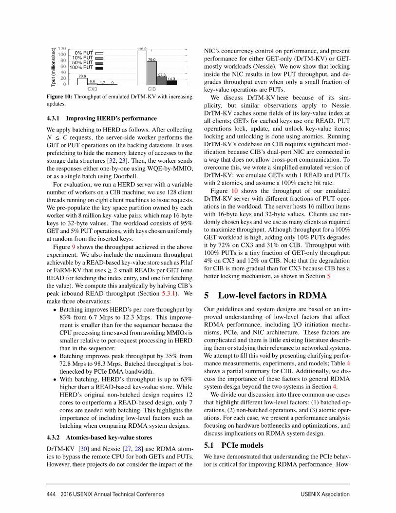
Figure 10: Throughput of emulated DrTM-KV with increasingupdates.
4.3.1 Improving HERD’s performance
We apply batching to HERD as follows. After collectingN ≤ C requests, the server-side worker performs theGET or PUT operations on the backing datastore. It usesprefetching to hide the memory latency of accesses to thestorage data structures [32, 23]. Then, the worker sendsthe responses either one-by-one using WQE-by-MMIO,or as a single batch using Doorbell.
For evaluation, we run a HERD server with a variablenumber of workers on a CIB machine; we use 128 clientthreads running on eight client machines to issue requests.We pre-populate the key space partition owned by eachworker with 8 million key-value pairs, which map 16-bytekeys to 32-byte values. The workload consists of 95%GET and 5% PUT operations, with keys chosen uniformlyat random from the inserted keys.
Figure 9 shows the throughput achieved in the aboveexperiment. We also include the maximum throughputachievable by a READ-based key-value store such as Pilafor FaRM-KV that uses ≥ 2 small READs per GET (oneREAD for fetching the index entry, and one for fetchingthe value). We compute this analytically by halving CIB’speak inbound READ throughput (Section 5.3.1). Wemake three observations:• Batching improves HERD’s per-core throughput by
83% from 6.7 Mrps to 12.3 Mrps. This improve-ment is smaller than for the sequencer because theCPU processing time saved from avoiding MMIOs issmaller relative to per-request processing in HERDthan in the sequencer.• Batching improves peak throughput by 35% from
72.8 Mrps to 98.3 Mrps. Batched throughput is bot-tlenecked by PCIe DMA bandwidth.• With batching, HERD’s throughput is up to 63%
higher than a READ-based key-value store. WhileHERD’s original non-batched design requires 12cores to outperform a READ-based design, only 7cores are needed with batching. This highlights theimportance of including low-level factors such asbatching when comparing RDMA system designs.
4.3.2 Atomics-based key-value stores
DrTM-KV [30] and Nessie [27, 28] use RDMA atom-ics to bypass the remote CPU for both GETs and PUTs.However, these projects do not consider the impact of the
NIC’s concurrency control on performance, and presentperformance for either GET-only (DrTM-KV) or GET-mostly workloads (Nessie). We now show that lockinginside the NIC results in low PUT throughput, and de-grades throughput even when only a small fraction ofkey-value operations are PUTs.
We discuss DrTM-KV here because of its sim-plicity, but similar observations apply to Nessie.DrTM-KV caches some fields of its key-value index atall clients; GETs for cached keys use one READ. PUToperations lock, update, and unlock key-value items;locking and unlocking is done using atomics. RunningDrTM-KV’s codebase on CIB requires significant mod-ification because CIB’s dual-port NIC are connected ina way that does not allow cross-port communication. Toovercome this, we wrote a simplified emulated version ofDrTM-KV: we emulate GETs with 1 READ and PUTswith 2 atomics, and assume a 100% cache hit rate.
Figure 10 shows the throughput of our emulatedDrTM-KV server with different fractions of PUT oper-ations in the workload. The server hosts 16 million itemswith 16-byte keys and 32-byte values. Clients use ran-domly chosen keys and we use as many clients as requiredto maximize throughput. Although throughput for a 100%GET workload is high, adding only 10% PUTs degradesit by 72% on CX3 and 31% on CIB. Throughput with100% PUTs is a tiny fraction of GET-only throughput:4% on CX3 and 12% on CIB. Note that the degradationfor CIB is more gradual than for CX3 because CIB has abetter locking mechanism, as shown in Section 5.
5 Low-level factors in RDMAOur guidelines and system designs are based on an im-proved understanding of low-level factors that affectRDMA performance, including I/O initiation mecha-nisms, PCIe, and NIC architecture. These factors arecomplicated and there is little existing literature describ-ing them or studying their relevance to networked systems.We attempt to fill this void by presenting clarifying perfor-mance measurements, experiments, and models; Table 4shows a partial summary for CIB. Additionally, we dis-cuss the importance of these factors to general RDMAsystem design beyond the two systems in Section 4.
We divide our discussion into three common use casesthat highlight different low-level factors: (1) batched op-erations, (2) non-batched operations, and (3) atomic oper-ations. For each case, we present a performance analysisfocusing on hardware bottlenecks and optimizations, anddiscuss implications on RDMA system design.
5.1 PCIe modelsWe have demonstrated that understanding the PCIe behav-ior is critical for improving RDMA performance. How-
8

USENIX Association 2016 USENIX Annual Technical Conference 445
Outbound verbs Inbound verbs
UD SENDs UD RECVs READs Atomics
Non-batch Batch Batch + HO Batch Batch + HO ≤ 64 B 128 B Z = 1 Z ≥ 4096
Rate (Mops) 80 101.6 157 82 122 121.6 76.2 2.24 52Bottleneck MMIO bw DMA bw NIC NIC NIC NIC IB bw PCIe RTT NIC
Table 4: Throughput and bottleneck of different modes of RDMA verbs on CIB. HO denotes the header-only optimization.
��
���
����
����
����
�� ��� ���� ���� ���� ����
�������
���������
���
��������������������
���������������������������������������
������������
(a) CIB
��
���
���
���
���
���
�� ��� ���� ���� ���� ������������������������
(b) CX3
��
���
���
���
�� ��� ���� ���� ���� ������������������������
(c) CX
Figure 12: Inbound READ and UC WRITE throughput, and the InfiniBand limit for READs. Note the different scales for Y axes.
��
���
���
���
���
����
����
�� ��� ���� ���� ���� ����
�������
���������
���
��������������������
����������������������������
��������������������������
(a) PCIe limits for UD SEND with batch size B
��������������
�� ��� ���
�������
���������
���
��������������������������������
���
���� ����
���
��� ������
���� ����
���
����
����
(b) Optimizations for UD SEND
Figure 11: (a) Peak batched and non-batched UD SENDthroughput on CIB, with batch size B; dotted lines show corre-sponding PCIe limits. (b) Effect of optimizations on single-coreUD SEND throughput with 60-byte payload (128-byte WQE).
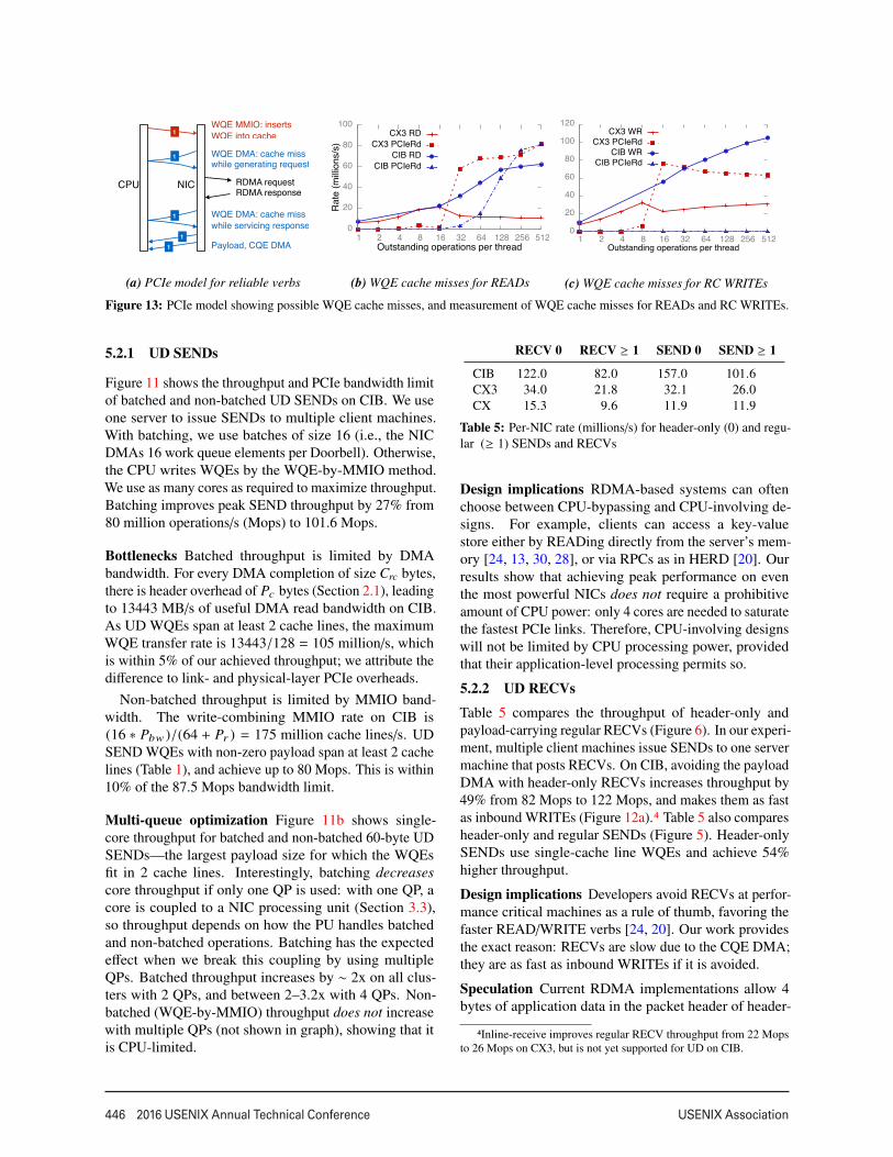
ever, deriving analytical models of PCIe behavior with-out access to proprietary/confidential NIC manuals andour limited resources—per–cache line PCIe counters andundocumented driver software—required extensive ex-perimentation and analysis. Our derived models arepresented in a slightly simplified form at several pointsin this paper (Figures 5, 6, 13). The exact analyticalmodels are complicated and depend on several factorssuch as the NIC, its PCIe capability, the verb and trans-port, the level of Doorbell batching, etc. To make our
models easily accessible, we instrumented the datapathof two Mellanox drivers (ConnectX-3 and Connect-IB)to provide statistics about PCIe bandwidth use (https://github.com/efficient/rdma_bench). Our modelsand drivers are restricted to requester-side PCIe behav-ior. We omit responder-side PCIe behavior because itis the same as described in our previous work [20]: in-bound READs and WRITEs generate one PCIe readand write, respectively; inbound SENDs trigger a RECVcompletion—we discuss the PCIe transactions for theRECV.
5.2 Batched operations
A limitation of batching on current hardware makes ituseful mainly for datagram transport: all operations in abatch must use the same queue pair because Doorbellsare per QP. This limitation seems fundamental to theparallel architecture of NICs: In a hypothetical NIC de-sign where Doorbells contained information relevant formultiple queue pairs (e.g., a compact encoding of “2 and1 new WQEs for QP 1 and QP 2, respectively”), sendingthe Doorbell to the NIC processing units handling theseQPs would require an expensive selective broadcast insidethe NIC. These PUs would then issue separate DMAs forWQEs, losing the coalescing advantage of batching. Thislimitation makes batching less useful for connected QPs,which provide only one-to-one communication betweentwo machines: the chances that a process has multiplemessages for the same remote machine are low in largedeployments. We therefore discuss batching for UD trans-port only.
9
446 2016 USENIX Annual Technical Conference USENIX Association
Payload, CQE DMA
WQE DMA: cache miss while generating request
RDMA requestRDMA response
WQE DMA: cache miss while servicing response
CPU NIC
WQE MMIO: insertsWQE into cache
1
1
11
1
(a) PCIe model for reliable verbs
��
���
���
���
���
����
�� �� �� �� ��� ��� ��� ���� ���� ����
�������
���������
�
���������������������������������
����������������
����������������
(b) WQE cache misses for READs
��
���
���
���
���
����
����
�� �� �� �� ��� ��� ��� ���� ���� �������������������������������������
����������������
����������������
(c) WQE cache misses for RC WRITEs
Figure 13: PCIe model showing possible WQE cache misses, and measurement of WQE cache misses for READs and RC WRITEs.
5.2.1 UD SENDs
Figure 11 shows the throughput and PCIe bandwidth limitof batched and non-batched UD SENDs on CIB. We useone server to issue SENDs to multiple client machines.With batching, we use batches of size 16 (i.e., the NICDMAs 16 work queue elements per Doorbell). Otherwise,the CPU writes WQEs by the WQE-by-MMIO method.We use as many cores as required to maximize throughput.Batching improves peak SEND throughput by 27% from80 million operations/s (Mops) to 101.6 Mops.
Bottlenecks Batched throughput is limited by DMAbandwidth. For every DMA completion of size Crc bytes,there is header overhead of Pc bytes (Section 2.1), leadingto 13443 MB/s of useful DMA read bandwidth on CIB.As UD WQEs span at least 2 cache lines, the maximumWQE transfer rate is 13443/128 = 105 million/s, whichis within 5% of our achieved throughput; we attribute thedifference to link- and physical-layer PCIe overheads.
Non-batched throughput is limited by MMIO band-width. The write-combining MMIO rate on CIB is(16 ∗ Pbw )/(64 + Pr ) = 175 million cache lines/s. UDSEND WQEs with non-zero payload span at least 2 cachelines (Table 1), and achieve up to 80 Mops. This is within10% of the 87.5 Mops bandwidth limit.
Multi-queue optimization Figure 11b shows single-core throughput for batched and non-batched 60-byte UDSENDs—the largest payload size for which the WQEsfit in 2 cache lines. Interestingly, batching decreasescore throughput if only one QP is used: with one QP, acore is coupled to a NIC processing unit (Section 3.3),so throughput depends on how the PU handles batchedand non-batched operations. Batching has the expectedeffect when we break this coupling by using multipleQPs. Batched throughput increases by ∼ 2x on all clus-ters with 2 QPs, and between 2–3.2x with 4 QPs. Non-batched (WQE-by-MMIO) throughput does not increasewith multiple QPs (not shown in graph), showing that itis CPU-limited.
RECV 0 RECV ≥ 1 SEND 0 SEND ≥ 1
CIB 122.0 82.0 157.0 101.6CX3 34.0 21.8 32.1 26.0CX 15.3 9.6 11.9 11.9
Table 5: Per-NIC rate (millions/s) for header-only (0) and regu-lar (≥ 1) SENDs and RECVs
Design implications RDMA-based systems can oftenchoose between CPU-bypassing and CPU-involving de-signs. For example, clients can access a key-valuestore either by READing directly from the server’s mem-ory [24, 13, 30, 28], or via RPCs as in HERD [20]. Ourresults show that achieving peak performance on eventhe most powerful NICs does not require a prohibitiveamount of CPU power: only 4 cores are needed to saturatethe fastest PCIe links. Therefore, CPU-involving designswill not be limited by CPU processing power, providedthat their application-level processing permits so.
5.2.2 UD RECVs
Table 5 compares the throughput of header-only andpayload-carrying regular RECVs (Figure 6). In our experi-ment, multiple client machines issue SENDs to one servermachine that posts RECVs. On CIB, avoiding the payloadDMA with header-only RECVs increases throughput by49% from 82 Mops to 122 Mops, and makes them as fastas inbound WRITEs (Figure 12a).4 Table 5 also comparesheader-only and regular SENDs (Figure 5). Header-onlySENDs use single-cache line WQEs and achieve 54%higher throughput.
Design implications Developers avoid RECVs at perfor-mance critical machines as a rule of thumb, favoring thefaster READ/WRITE verbs [24, 20]. Our work providesthe exact reason: RECVs are slow due to the CQE DMA;they are as fast as inbound WRITEs if it is avoided.
Speculation Current RDMA implementations allow 4bytes of application data in the packet header of header-
4Inline-receive improves regular RECV throughput from 22 Mopsto 26 Mops on CX3, but is not yet supported for UD on CIB.
10

USENIX Association 2016 USENIX Annual Technical Conference 447
only SENDs. For applications that require larger mes-sages, header-only SEND/RECV can be used if specu-lation is possible; we demonstrated such a design foran 8-byte sequencer in Section 4.2. In general, specu-lation works as follows: clients transmit their expectedresponse along with requests, and get a small confirma-tion response in the common case. For example, in akey-value store with client-side caching, clients can sendGET requests with the key and its cached version number(using a WRITE or regular SEND). The server replieswith a header-only “OK” SEND if the version is valid.
There are applications for which 4 bytes of per-messagedata suffices. For example, some database tables in theTPC-C [29] benchmark have primary key size between 2and 3 bytes. A table access request can be sent using aheader-only SEND (using the remaining 1 byte to specifythe table ID), while the response may need a larger SEND.
5.3 Non-batched operations5.3.1 Inbound READs and WRITEs
Figure 12 shows the measured throughput of inboundREADs and UC WRITEs, and the InfiniBand bandwidthlimit of inbound READs. We do not show the InfiniBandlimit for WRITEs and the PCIe limits as they are higher.
Bottlenecks On our clusters, inbound READs andWRITEs are initially bottlenecked by the NIC’s process-ing power, and then by InfiniBand bandwidth. The pay-load size at which bandwidth becomes a bottleneck de-pends on the NIC’s processing power relative to band-width. For READs, the transition point is approximately128 bytes, 256 bytes, and 64 bytes for CX, CX3, andCIB, respectively. CIB NICs are powerful enough to satu-rate 112 Gbps with 64-byte READs, whereas CX3 NICsrequire 256-byte READs to saturate 56 Gbps.
Implications The transition point is an important factorfor systems that make tradeoffs between the size andnumber of READs: For key-value lookups of small items(∼32 bytes), FaRM’s key-value store [13] can use onelarge (∼256-byte) READ. In a client-server design whereinbound READs determine GET performance, this designperforms well on CX3 because 32- and 256-byte READshave similar throughput; other designs such as DrTM-KV [30] and Pilaf [24] that instead use 2–3 small READsmay provide higher throughput on CIB.
5.3.2 Outbound READs and WRITEs
For brevity, we only present a summary of the perfor-mance of non-batched outbound operations on CIB. Out-bound UC WRITEs larger than 28 bytes, i.e., WRITEswith WQEs spanning more than one cache line (Ta-ble 1), achieve up to 80 Mops and are bottlenecked byPCIe MMIO throughput, similar to non-batched outboundSENDs (Figure 11a). READs achieve up to 88 Mops and
��������������������
�� �� ��� ��� ���� ����� �����
�������
���������
�
�����������������������������
������
Figure 14: Atomics throughput with increasing concurrency
are bottlenecked by NIC processing power.
Achieving high outbound throughput requires main-taining multiple outstanding requests via pipelining.When the CPU initiates an RDMA operation, the workqueue element is inserted into the NIC’s WQE cache.However, if the CPU injects new WQEs faster than theNIC’s processing speed, this WQE can be evicted bynewer WQEs. This can cause cache misses when theNIC eventually processes this WQE while generating itsRDMA request packets, while servicing its RDMA re-sponse, or both. Figure 13a summarizes this model.
To quantify this effect, we conduct the following ex-periment on CIB: 14 requester threads on a server issuewindows of N 8-byte READs or WRITEs over reliabletransport to 14 remote processes. In Figures 13b and 13c,we show the cumulative RDMA request rate, and the ex-tent of WQE cache misses using the PCIeRdCur counterrate. Each thread waits for the N requests to completebefore issuing the next window. We use all 14 cores onthe server to generate the maximum possible request rate,and RC transport to include cache misses generated whileprocessing ACKs for WRITEs. We make the followingobservations, showing the importance of the WQE cachein improving and understanding RDMA throughput:• The optimal window size for maximum throughput
is not obvious: throughput does not always increasewith increasing window size, and is dependent on theNIC. For example, N = 16 and N = 512 maximizeREAD throughput on CX3 and CIB respectively.• Higher RDMA throughput may be obtained at the
cost of PCIe reads. For example, on CIB, bothREAD throughput and PCIe read rate increases asN increases. Although the largest N is optimal for amachine that only issues outbound READs, it maybe suboptimal if it also serves other operations.• CIB’s NIC can handle the CPU’s peak WQE injec-
tion rate for WRITEs and never suffers cache misses.This is not true for READs, indicating that they re-quire more NIC processing than reliable WRITEs.
5.4 Atomic operationsNIC processing units contend for locks during atomicoperations (Section 3.4). The performance of atomicsdepends on the amount of parallelism in the workloadwith respect to the NIC’s internal locking scheme. To vary
11

448 2016 USENIX Annual Technical Conference USENIX Association
the amount of parallelism, we create an array of Z 8-bytecounters in a server’s memory, and multiple remote clientprocesses issue atomic operations on counters chosenrandomly at each iteration. Figure 14 shows the totalclient throughput in this experiment. For CX3, it remains2.7 Mops irrespective of Z; for CIB, it rises to 52 Mops.
Inferring the locking mechanism The flatness of CX3’sthroughput graph indicates that it serializes all atomicoperations. For CIB, we measured performance withrandomly chosen pairs of addresses and observed lowerperformance for pairs where both addresses have the same12 LSBs. This strongly suggests that CIB uses 4096 buck-ets to slot atomic operations by address—a new operationwaits until its slot is empty.
Bottlenecks and implications Throughput on CX3 islimited by PCIe latency because of serialization. For CIB,buffering and computation needed for PCIe read-modify-write makes NIC processing power the bottleneck.
The abysmal throughput for Z = 1 on both NICs re-affirms that atomics are a poor choice for a sequencer; ouroptimized sequencer in Section 4 provides 12.2x higherperformance with a single server CPU core. A lock ser-vice for data stores, however, might use a larger Z . Atom-ics could perform well if such an application used CIB,but they are very slow with CX3, which is the NIC used inprior work [27, 30]. With CIB, careful lock placement isstill necessary. For example, if page-aligned data recordshave their lock variables at the same offset in the record,all lock requests will have the same 12 LSBs and will getserialized. A deterministic scheme that places the lockat different offsets in different records, or a scheme thatkeeps locks separate from the data will perform better.
6 Related workHigh-performance RDMA systems Designing high-performance RDMA systems is an active area of research.Recent advances include several key-value storage sys-tems [24, 13, 20, 30, 28] and distributed transaction pro-cessing systems [30, 12, 14, 11]. A key design decision ineach of these systems is the choice of verbs, made usinga microbenchmark-based performance comparison. Ourwork shows that there are more dimensions to these com-parisons than these projects explore: two verbs cannotbe exhaustively compared without exploring the space oflow-level factors and optimizations, each of which canoffset verb performance by several factors.
Low-level factors in network I/O Although there is alarge body of work that measures the throughput and CPUutilization of network communication [18, 16, 26, 13, 20],there is less existing literature on understanding the low-level behavior of network cards. NIQ [15] presents a high-level picture of the PCIe interactions between an Ethernet
NIC and CPUs, but does not discuss the more subtleinteractions that occur during batched transfers. Lee etal. [22] study the PCIe behavior of Ethernet cards usinga PCIe protocol analyzer, and divide the PCIe traffic intoDoorbell traffic, Ethernet descriptor traffic, and actual datatraffic. Similarly, analyzing RDMA NICs using a PCIeanalyzer may reveal more insights into their behavior thanwhat is achievable using PCIe counters.
7 ConclusionDesigning high-performance RDMA systems requires adeep understanding of low-level RDMA details such asPCIe behavior and NIC architecture: our best sequenceris ∼50x faster than an existing design and scales perfectly,our optimized HERD key-value store is up to 83% fasterthan the original, and our fastest transmission method isup to 3.2x faster than the commonly-used baseline. Webelieve that by presenting clear guidelines, significantoptimizations based on these guidelines, and tools andexperiments for low-level measurements on their hard-ware, our work will encourage researchers and developersto develop a better understanding of RDMA hardwarebefore using it in high-performance systems.
Acknowledgments We are tremendously grateful toJoseph Moore and NetApp for providing access to theCIB cluster. We thank Hyeontaek Lim and Sol Boucherfor providing feedback, and Liuba Shrira for shepherd-ing. Emulab [31] and PRObE [17] resources were usedin our experiments. PRObE is supported in part by NSFawards CNS-1042537 and CNS-1042543 (PRObE). Thiswork was supported by funding from the National Sci-ence Foundation under awards 1345305 and 1314721,and by Intel via the Intel Science and Technology Centerfor Cloud Computing (ISTC-CC).
Appendix A. WQE-by-MMIO and Door-bell PCIe use
We denote the doorbell size by d. The total data transmit-ted from CPU to NIC with the WQE-by-MMIO methodis Tb f = 10 ∗ (�65/64� ∗ (64 + Pr )) bytes. With cacheline padding, 65-byte WQEs are laid out in 128-byteslots in host memory; assuming Crc = 128, Tdb =
(d+Pr )+(10∗(128+Pc )) bytes. We ignore the PCIe link-layer traffic since it is small compared to transaction-layertraffic: it is common to assume 2 link-layer packets (1flow control update and 1 acknowledgment, both 8 bytes)per 4-5 TLPs [9], making the link-layer overhead < 5%.Substituting d = 8 gives Tb f = 1800, and Tdb = 1534.
12
USENIX Association 2016 USENIX Annual Technical Conference 449
References
[1] Infiniband architecture specification volume 1.https://cw.infinibandta.org/document/dl/7859.
[2] Intel Atom Processor C2000 Product Family for Mi-croserver. http://www.intel.in/content/dam/www/public/us/en/documents/datasheets/atom-c2000-microserver-datasheet.pdf.
[3] Intel Xeon Processor E5-1600/2400/2600/4600v3 Product Families. http://www.intel.com/content/dam/www/public/us/en/documents/datasheets/xeon-e5-v3-datasheet-vol-2.pdf.
[4] Intel Xeon Processor E5-1600/2400/2600/4600(E5-Product Family) Product Families.http://www.intel.com/content/dam/www/public/us/en/documents/datasheets/xeon-e5-1600-2600-vol-2-datasheet.pdf.
[5] Intel Xeon Processor D-1500 Product Family.http://www.intel.in/content/dam/www/public/us/en/documents/product-briefs/xeon-processor-d-brief.pdf.
[6] Intel Xeon Phi Processor Knights Land-ing Architectural Overview. https://www.nersc.gov/assets/Uploads/KNL-ISC-2015-Workshop-Keynote.pdf.
[7] Mellanox ConnectX-4 product brief.http://www.mellanox.com/related-docs/prod_silicon/PB_ConnectX-4_VPI_Card.pdf.
[8] Mellanox OFED for linux user manual.http://www.mellanox.com/related-docs/prod_software/Mellanox_OFED_Linux_User_
Manual_v2.2-1.0.1.pdf.[9] Understanding Performance of PCI Express
Systems. http://www.xilinx.com/support/documentation/white_papers/wp350.pdf.
[10] M. Balakrishnan, D. Malkhi, V. Prabhakaran,T. Wobber, M. Wei, and J. D. Davis. CORFU: ashared log design for flash clusters. In Proc. 9thUSENIX NSDI, Apr. 2012.
[11] C. Binnig, U. Çetintemel, A. Crotty, A. Galakatos,T. Kraska, E. Zamanian, and S. B. Zdonik. The endof slow networks: It’s time for a redesign. CoRR,abs/1504.01048, 2015. URL http://arxiv.org/abs/1504.01048.
[12] Y. Chen, X. Wei, J. Shi, R. Chen, and H. Chen. Fastand general distributed transactions using RDMAand HTM. In Proc. 11th ACM European Conferenceon Computer Systems (EuroSys), Apr. 2016.
[13] A. Dragojevic, D. Narayanan, O. Hodson, andM. Castro. FaRM: Fast remote memory. In Proc.
11th USENIX NSDI, Apr. 2014.[14] A. Dragojevic, D. Narayanan, E. B. Nightingale,
M. Renzelmann, A. Shamis, A. Badam, and M. Cas-tro. No compromises: Distributed transactions withconsistency, availability, and performance. In Proc.25th ACM Symposium on Operating Systems Prin-ciples (SOSP), Oct. 2015.
[15] M. Flajslik and M. Rosenblum. Network interfacedesign for low latency request-response protocols.In Proc. USENIX Annual Technical Conference,June 2013.
[16] S. Gallenmüller, P. Emmerich, F. Wohlfart,D. Raumer, and G. Carle. Comparison of frame-works for high-performance packet io. In ANCS,2015.
[17] G. Gibson, G. Grider, A. Jacobson, and W. Lloyd.PRObE: A Thousand-Node Experimental Clusterfor Computer Systems Research.
[18] S. Han, K. Jang, K. Park, and S. Moon. Packet-Shader: a GPU-accelerated software router. In Proc.ACM SIGCOMM, Aug. 2010.
[19] S. Hauger, T. Wild, A. Mutter, A. Kirstaedter,K. Karras, R. Ohlendorf, F. Feller, and J. Scharf.Packet processing at 100 Gbps and beyond - chal-lenges and perspectives. In Photonic Networks,2009 ITG Symposium on, 2009.
[20] A. Kalia, M. Kaminsky, and D. G. Andersen. UsingRDMA efficiently for key-value services. In Proc.ACM SIGCOMM, Aug. 2014.
[21] A. Kalia, D. Zhou, M. Kaminsky, and D. G. Ander-sen. Raising the bar for using GPUs in softwarepacket processing. In Proc. 12th USENIX NSDI,May 2015.
[22] S. Larsen and B. Lee. Platform io dma transactionacceleration. In CACHES. ACM, 2011.
[23] H. Lim, D. Han, D. G. Andersen, and M. Kaminsky.MICA: A holistic approach to fast in-memory key-value storage. In Proc. 11th USENIX NSDI, Apr.2014.
[24] C. Mitchell, Y. Geng, and J. Li. Using one-sidedRDMA reads to build a fast, CPU-efficient key-valuestore. In Proc. USENIX Annual Technical Confer-ence, June 2013.
[25] R. Nishtala, H. Fugal, S. Grimm, M. Kwiatkowski,H. Lee, H. C. Li, R. McElroy, M. Paleczny, D. Peek,P. Saab, D. Stafford, T. Tung, and V. Venkatara-mani. Scaling Memcache at Facebook. In Proc.10th USENIX NSDI, Apr. 2013.
[26] L. Rizzo. netmap: a novel framework for fast packetI/O. In Proceedings of the 2012 USENIX conferenceon Annual Technical Conference, June 2012.
[27] T. Szepesi, B. Wong, B. Cassell, , and T. Brecht.
13

450 2016 USENIX Annual Technical Conference USENIX Association
Designing a low-latency cuckoo hash table for write-intensive workloads. In WSRC, 2014.
[28] T. Szepesi, B. Cassell, B. Wong, T. Brecht, andX. Liu. Nessie: A decoupled, client-driven, key-value store using RDMA. Technical Report CS-2015-09, University of Waterloo, David R. CheritonSchool of Computer Science, Waterloo, Canada,June 2015.
[29] TPC-C. TPC benchmark C. http://www.tpc.org/tpcc/.
[30] X. Wei, J. Shi, Y. Chen, R. Chen, and H. Chen. Fastin-memory transaction processing using RDMA andHTM. In Proceedings of the 25th Symposium onOperating Systems Principles (SOSP), 2015.
[31] B. White, J. Lepreau, L. Stoller, R. Ricci, S. Gu-ruprasad, M. Newbold, M. Hibler, C. Barb, andA. Joglekar. An integrated experimental environ-ment for distributed systems and networks. In Proc.5th USENIX OSDI, pages 255–270, Dec. 2002.
[32] D. Zhou, B. Fan, H. Lim, D. G. Andersen, andM. Kaminsky. Scalable, High Performance EthernetForwarding with CuckooSwitch. In Proc. 9th Inter-national Conference on emerging Networking EX-periments and Technologies (CoNEXT), Dec. 2013.
14