design & implementation a corporate network using inter-vlan
TRANSCRIPT
DESIGN & IMPLEMENTATION A CORPORATE
NETWORK USING INTER-VLAN ROUTING
PROTOCOL
Project Supervisor:
Dr.Mohamed Ruhul Amin
Professor,Department of ECE
East West University
Developed by:
Md.Kamrul Hasan ID:2011-1-55-022
Shamim Ahammed ID:2011-2-55-006
A Project Submitted in Partial fulfillment of the Requirements for the Degree of
Bachelor of Science in Electronics & Telecommunications Engineering
DEPARTMENT OF ELECTRONICS & COMMUNICATIONS ENGINEERING
EAST WEST UNIVERSITY
December 2015
DECLARATION
We here by declare that we carried out the work reported in this
project in the Department of Electronics and communication
Engineering ,East West University ,under the supervision of Professor,
Dr. Mohamed Ruhul Amin .We also declare that no part of this work
has been submitted elsewhere partially or fully for the award of any
other degree or diploma .Any material reproduced in this project has
been properly acknowledged .All sources of knowledge used have been
duly acknowledged.
……………………………….. …………………………………
Md.Kamrul Hasan Shamim Ahammed
ID:2011-1-55-022 ID:2011-2-55-006
I
Approval
The Project titled as ‘DESIGN & IMPLEMENTATION A CORPORATE
NETWORK USING INTER-VLAN ROUTING PROTOCOL’ has been
submitted to the following respected members of the Board of
Examiners of the Faculty of Engineering for partial fulfillment of the
requirements for the degree of Bachelor of Science in Electronics &
Telecommunications Engineering by the following students and has
been accepted as satisfactory.
The thesis report can be considered for evaluation.
…………………………………………
December 2015
Dr.Mohamed Ruhul Amin
Professor,Department of ECE
East West University
II
Acceptance
This research report presented to the department of
electronics and communication engineering, East West
University is submitted in partial fulfillment of the requirement
for degree of B.Sc. in Electronics & Telecommunication
Engineering, under complete supervision of the undersigned.
……………………………………..
Dr.Mohamed Ruhul Amin
Professor,Department of ECE
East West University
III

ACKNOWLEDGEMENTS
First and foremost with all my heartiest devotion we are grateful to
almighty Allah for blessing me with such opportunity of learning and
ability to successfully complete the task.
We would like to thank our department for giving us this chance to do
this project. We want to express our special thanks and deep
appreciation to our supervisor of Professor, Dr. Mohamed Ruhul Amin
; who was kind enough to allocate his valuable time to provide me with
his humble guidance, motivating thought and encouragement.
IV
ABSTRACT
Every small and large organization use computer network to share their resources. The
size of network is increasing day by day. They are connecting their network to the public
network such as Internet.A network has been designed that represents a real time
environment of an organization. The organization has been subdivided into different
departments by implementing VLANs for proper management. Also these different
departments can communicate with each other using Inter VLAN Routing for controlled
flow of information. An ISP environment has been created using NBMA frame relay to
control traffic. Redistribution of routing protocols is being used for better routing OSPF
protocols. PRAN RFL GROUP company whose have main 7 branches and 7 sub
branches in Bangladesh. In future this company will increase their sub benches. 7
divisions have 7 main branches and 7 districts have 7 sub branches in Bangladesh.
Every main branches have Admin VLAN and sub branches have MKT and SALES
VLAN. Main and sub branches VLAN will increases day by day. For
intercommunicating all VLAN, we use inter-VLAN Routing with OSPF Routing protocol.
First, in this project we configure 7 main branches and also 7 sub branches. Second, we create VLAN all main branches and sub branches. Third, we configure OSPF in all main branches Router and sub branches Layer-3 switch. Finally, we configure inter-VLAN Routing in all main and sub branches and run all configure.
V
DESIGN & IMPLEMENTATION A CORPORATE NETWORK USING INTER-VLAN ROUTINGPROTOCOL
2015
Contents Chapter 1 ................................................................................................................................................. 3
1.1 Introduction ............................................................................................................................. 3
1.2 About the Project .................................................................................................................... 3
1.3 Purpose of the project ............................................................................................................. 3
2 Chapter 2 ......................................................................................................................................... 4
OSPF Routing Protocol ....................................................................................................................... 4
2.1 What is OSPF routing ............................................................................................................. 4
2.2 Why we use OSPF in this project? .......................................................................................... 4
2.3 Basic Introduction of OSPF ...................................................................................................... 5
2.4 OSPF Neighbor State ........................................................................................................... 6
2.5 OSPF Network Types ........................................................................................................... 7
2.6 Configuring Basic OSPF .......................................................................................................... 8
2.7 OSPF Virtual Links ................................................................................................................... 9
2.8 OSPF Area Types ................................................................................................................... 10
2.9 OSPF Operation ..................................................................................................................... 13
2.10 OSPF VS RIP .......................................................................................................................... 13
3 Chapter 3 ....................................................................................................................................... 14
3.1 Virtual Local Area Network ................................................................................................... 14
3.2 What is VLAN......................................................................................................................... 14
3.3 Why we use VLAN ................................................................................................................. 14
3.4 VLAN Types ........................................................................................................................... 15
3.5 Purpose of VLANs: ................................................................................................................ 15
3.6 VLAN Types of links/ports ..................................................................................................... 16
4 Chapter 4 ....................................................................................................................................... 17
4.1 INTER –VLAN ..................................................................................................................... 17
4.2 What is Inter-VLAN ............................................................................................................. 17
4.3 Inter-VLAN Routing ............................................................................................................. 17
4.4 Configuring of Inter-VLAN Routing: ................................................................................... 17
4.5 ..................................................................................................................................................... 18
5 Chapter 5 ....................................................................................................................................... 23
5.1 Structure of Corporate House ............................................................................................... 23
DESIGN & IMPLEMENTATION A CORPORATE NETWORK USING INTER-VLAN ROUTINGPROTOCOL
2015
5.2 The Basics of Corporate Office Structure ........................................................................... 23
5.3 The Basic Structure of Our Project Corporate House ........................................................... 25
Chapter 6 .............................................................................................................................................. 28
6 Design A Network And IP Plan ...................................................................................................... 28
6.1 Design whole diagram of Project .......................................................................................... 28
6.2 Executive Summary ............................................................................................................... 29
6.3 Safe Architecture Principles .................................................................................................. 30
6.4 Underlying Network Design .................................................................................................. 31
6.5 Medium Enterprise Network Security Design ....................................................................... 31
6.6 Network Foundation Protection ........................................................................................... 32
6.7 IP Plan for this Project VLANS ............................................................................................... 32
7 Chapter 5 ....................................................................................................................................... 35
7.1 Implementation of Inter-VLAN Communication ................................................................. 35
7.2 Packet Tracer Network Simulator: ........................................................................................ 35
7.3 BHOLA SUB BRANCHE: .......................................................................................................... 37
8 Chapter 8 ....................................................................................................................................... 42
8.1 Result & Output .................................................................................................................. 42
8.2 Simulation Results ................................................................................................................ 42
8.3 Inter-VLAN Routing Bhola to Comilla,Tangail,jessore,Bogra,Gaibandha&Sunamganj ......... 42
8.4 Simulation Result Analysis ................................................................................................... 44
9 Chapter 9 ....................................................................................................................................... 45
9.1 Conclusion ............................................................................................................................. 45
9.2 Future Work Scope ............................................................................................................... 45
9.3 Appendix ............................................................................................................................... 46
9.4 Reference .............................................................................................................................. 52
LIST OF FIGURE:
Figure 1:BASIC OSPF CONFIGURATION ................................................................................................. 8
Figure 2:OSPF VIRTUAL LINKS ................................................................................................................ 9
Figure 3:INTER-VLAN ROUTING ............................................................................................................ 17
Figure 4:BASIC VLAN STRUCTURE OF A CORPORATE HOUSE ............................................................... 26
Figure 5:WHOLE DIAGRAM OF A PROJECT ........................................................................................... 29
DESIGN & IMPLEMENTATION A CORPORATE NETWORK USING INTER-VLAN ROUTINGPROTOCOL
2015
Chapter 1
1.1 Introduction
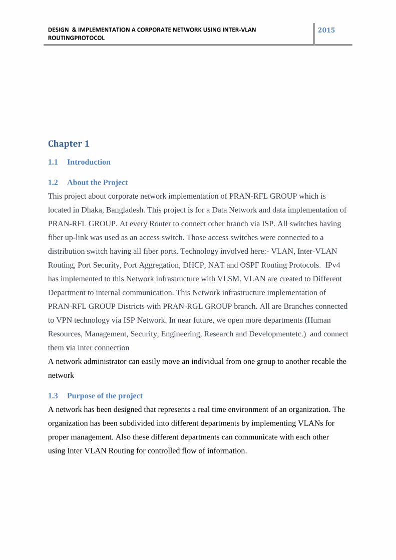
1.2 About the Project
This project about corporate network implementation of PRAN-RFL GROUP which is
located in Dhaka, Bangladesh. This project is for a Data Network and data implementation of
PRAN-RFL GROUP. At every Router to connect other branch via ISP. All switches having
fiber up-link was used as an access switch. Those access switches were connected to a
distribution switch having all fiber ports. Technology involved here:- VLAN, Inter-VLAN
Routing, Port Security, Port Aggregation, DHCP, NAT and OSPF Routing Protocols. IPv4
has implemented to this Network infrastructure with VLSM. VLAN are created to Different
Department to internal communication. This Network infrastructure implementation of
PRAN-RFL GROUP Districts with PRAN-RGL GROUP branch. All are Branches connected
to VPN technology via ISP Network. In near future, we open more departments (Human
Resources, Management, Security, Engineering, Research and Developmentetc.) and connect
them via inter connection
A network administrator can easily move an individual from one group to another recable the
network
1.3 Purpose of the project
A network has been designed that represents a real time environment of an organization. The
organization has been subdivided into different departments by implementing VLANs for
proper management. Also these different departments can communicate with each other
using Inter VLAN Routing for controlled flow of information.
DESIGN & IMPLEMENTATION A CORPORATE NETWORK USING INTER-VLAN ROUTINGPROTOCOL
2015
2 Chapter 2
OSPF Routing Protocol
2.1 What is OSPF routing
OSPF is standard routing protocol, that’s been implemented by a wide verity of network
vendor including CISCO. Open Shortest Path First is a link state routing protocol (LSRP) that
uses the Shortest Path First network communication algorithm to calculate the shortest
connection path between known devices.
2.2 Why we use OSPF in this project?
Open Shortest Path First (OSPF) is a relatively new kid to the Internet routing scenario
adaptive
. Consider of area and autonomous system .
.Routing update and traffic minimize allows stability .
.Support VLSM by CIDR.
.#unlimited hope count allows multi-vendor deployment (open stander ).
.Open Shortest Path First is a link state routing protocol.
OSPF traffic is multicast .The main reason behind the OSPF protocol being faster is
that whenever changes are made in the routing tables, only the new or updated values
are transferred, instead of sending the entire code.
DESIGN & IMPLEMENTATION A CORPORATE NETWORK USING INTER-VLAN ROUTINGPROTOCOL
2015
The main reason behind the OSPF protocol being faster is that whenever changes are made in
the routing tables, only the new or updated values are transferred, instead of sending the
entire code.
2.3 Basic Introduction of OSPF
OSPF adheres to the following Link State characteristics:
• OSPF employs a hierarchical network design using Areas.
• OSPF will form neighbor relationships with adjacent routers in the same Area.
• Instead of advertising the distance to connected networks, OSPF advertises the
status of directly connected links using Link-StateAdvertisements (LSAs).
• OSPF sends updates (LSAs) when there is a change to one of its links, and will only
send the change in the update. LSAs are additionally refreshed every 30 minutes.
• OSPF traffic is multicast either to address 224.0.0.5 (all OSPF routers) or
224.0.0.6 (all Designated Routers).
• OSPF uses the Dijkstra Shortest Path First algorithm to determine the shortest
path.
• OSPF is a classless protocol, and thus supports VLSMs.
The OSPF process builds and maintains three separate tables:
• A neighbor table – contains a list of all neighboring routers.
• A topology table – contains a list of all possible routes to all known networks
within an area.
• A routing table – contains the best route for each known network.
DESIGN & IMPLEMENTATION A CORPORATE NETWORK USING INTER-VLAN ROUTINGPROTOCOL
2015
2.4 OSPF Neighbor State
Neighbor adjacencies will progress through several states, including:
Down – indicates that no Hellos have been heard from the neighboringrouter.
Init – indicates a Hello packet has been heard from the neighbor,
but two-way communication has not yet been initialized.
2-Way – indicates that bidirectional communication has been established.Recall that Hello
packets contain a neighbor field. Thus, communication is considered 2-Way once a router
sees its own Router ID in its neighbor’s Hello Packet. Designated and Backup
Designated Routers are elected at this stage.
ExStart– indicates that the routers are preparing to share link stateinformation.
Master/slave relationships are formed between routers to determine who will begin
the exchange.
Exchange – indicates that the routers are exchanging Database Descriptors (DBDs). DBDs
contain a description of the router’s Topology Database. Arouter will examine a neighbor’s
DBD to determine if it has information to share.
Loading – indicates the routers are finally exchanging Link State Advertisements,
containing information about all links connected to eachrouter. Essentially, routers are
sharing their topology tables with each other.
Full – indicates that the routers are fully synchronized. The topology table ofall routers in the
area should now be identical. Depending on the “role” of the neighbor, the state may appear
as:
• Full/DR – indicating that the neighbor is a Designated Router (DR)
• Full/BDR – indicating that the neighbor is a Backup DesignatedRouter (BDR)
DESIGN & IMPLEMENTATION A CORPORATE NETWORK USING INTER-VLAN ROUTINGPROTOCOL
2015
• Full/DROther – indicating that the neighbor is neither the DR orBDR
2.5 OSPF Network Types
OSPF’s functionality is different across several different network topology types. OSPF’s
interaction with Frame Relay will be explained in another section
Broadcast Multi-Access – indicates a topology where broadcast occurs.
• Examples include Ethernet, Token Ring, and ATM.
• OSPF will elect DRs and BDRs.
Point-to-Point – indicates a topology where two routers are directlyconnected.
• An example would be a point-to-point T1.
OSPF will not elect DRs and BDRs.
Point-to-Multipoint – indicates a topology where one interface can connectto multiple
destinations. Each connection between a source and destination is treated as a point-to-point
link.
• An example would be Point-to-Multipoint Frame Relay.
• OSPF will not elect DRs and BDRs.
.
Non-broadcast Multi-access Network (NBMA) – indicates a topologywhere one
DESIGN & IMPLEMENTATION A CORPORATE NETWORK USING INTER-VLAN ROUTINGPROTOCOL
2015
interface can connect to multiple destinations; however, broadcasts cannot be sent
across a NBMA network.
• An example would be Frame Relay.
• OSPF will elect DRs and BDRs.
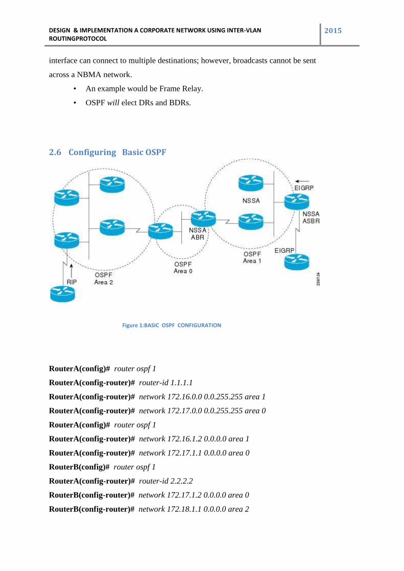
2.6 Configuring Basic OSPF
Figure 1:BASIC OSPF CONFIGURATION
RouterA(config)# router ospf 1
RouterA(config-router)# router-id 1.1.1.1
RouterA(config-router)# network 172.16.0.0 0.0.255.255 area 1
RouterA(config-router)# network 172.17.0.0 0.0.255.255 area 0
RouterA(config)# router ospf 1
RouterA(config-router)# network 172.16.1.2 0.0.0.0 area 1
RouterA(config-router)# network 172.17.1.1 0.0.0.0 area 0
RouterB(config)# router ospf 1
RouterA(config-router)# router-id 2.2.2.2
RouterB(config-router)# network 172.17.1.2 0.0.0.0 area 0
RouterB(config-router)# network 172.18.1.1 0.0.0.0 area 2
DESIGN & IMPLEMENTATION A CORPORATE NETWORK USING INTER-VLAN ROUTINGPROTOCOL
2015
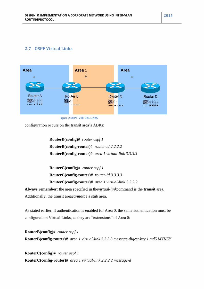
2.7 OSPF Virtual Links
configuration occurs on the transit area’s ABRs:
RouterB(config)# router ospf 1
RouterB(config-router)# router-id 2.2.2.2
RouterB(config-router)# area 1 virtual-link 3.3.3.3
RouterC(config)# router ospf 1
RouterC(config-router)# router-id 3.3.3.3
RouterC(config-router)# area 1 virtual-link 2.2.2.2
Always remember: the area specified in thevirtual-linkcommand is the transit area.
Additionally, the transit areacannotbe a stub area.
As stated earlier, if authentication is enabled for Area 0, the same authentication must be
configured on Virtual Links, as they are “extensions” of Area 0:
RouterB(config)# router ospf 1
RouterB(config-router)# area 1 virtual-link 3.3.3.3 message-digest-key 1 md5 MYKEY
RouterC(config)# router ospf 1
RouterC(config-router)# area 1 virtual-link 2.2.2.2 message-d
Figure 2:OSPF VIRTUAL LINKS
DESIGN & IMPLEMENTATION A CORPORATE NETWORK USING INTER-VLAN ROUTINGPROTOCOL
2015
2.8 OSPF Area Types In order to control the propagation of LSAs in the OSPF domain, several area types
were developed.
Standard Area –A “normal” OSPF area.
• Routers within a standard area will share Router (Type 1) and Network (Type 2)
LSAs to build their topology tables. Once fully synchronized, routers within an
area will all have identical topology tables.
• Standard areas will accept Network Summary (Type 3) LSAs, which
contain the routes to reach networks in all other areas.
• Standard areas will accept ASBR Summary (Type 4) and External (Type 5)
LSAs, which contain the route to the ASBR and routes to external networks,
respectively.
Configuration of standard areas is straight forward:
Router(config)# router ospf 1
Router(config-router)# network 10.1.0.0 0.0.7.255 area 1
Stub Area –Prevents external routes from flooding into an area.
• Like Standard areas, Stub area routers will share Type 1 and Type 2 LSAs to
build their topology tables.
• Stub areas will also accept Type 3 LSAs to reach other areas.
• Stub areas will not accept Type 4 or Type 5 LSAs, detailing routes to external
networks.
The purpose of Stub areas is to limit the number of LSAs flooded into the area, to conserve
bandwidth and router CPUs. The Stub’s ABR will automatically inject adefault routeinto the
DESIGN & IMPLEMENTATION A CORPORATE NETWORK USING INTER-VLAN ROUTINGPROTOCOL
2015
Stub area, so that those routerscan reach the external networks. The ABR will be the next-hop
for the default route.
Configuration of stub areas is relatively simple:
Router(config)# router ospf 1
Router(config-router)# network 10.1.0.0 0.0.7.255 area 1
Router(config-router)# area 1 stub
The area 1 stub command must be configured on No ASBRs are allowed in a Stub area,
allrouters in the Stub area.
Totally Stubby Area –Prevents both inter-areaandexternal routes fromflooding into an
area.
• Like Standard and Stub areas, Totally Stubby area routers will share Type 1
and Type 2 LSAs to build their topology tables.
• Totally Stubby areas will not accept Type 3 LSAs to other areas.
• Totally Stubby areas will also not accept Type 4 or Type 5 LSAs, detailing
routes to external networks.
• Configuration of totally stubby areas is relatively simple:
• Router(config)# router ospf 1
• Router(config-router)# network 10.1.0.0 0.0.7.255 area 1
• Router(config-router)# area 1 stub no-summary
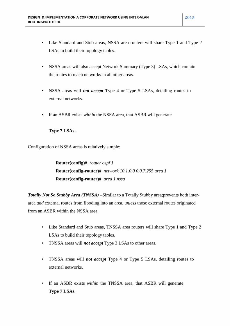
Not So Stubby Area (NSSA) –Similar to a Stub area; prevents externalroutes from
flooding into an area, unless those external routes originated from an ASBR within the
NSSA area.
DESIGN & IMPLEMENTATION A CORPORATE NETWORK USING INTER-VLAN ROUTINGPROTOCOL
2015
• Like Standard and Stub areas, NSSA area routers will share Type 1 and Type 2
LSAs to build their topology tables.
• NSSA areas will also accept Network Summary (Type 3) LSAs, which contain
the routes to reach networks in all other areas.
• NSSA areas will not accept Type 4 or Type 5 LSAs, detailing routes to
external networks.
• If an ASBR exists within the NSSA area, that ASBR will generate
Type 7 LSAs.
Configuration of NSSA areas is relatively simple:
Router(config)# router ospf 1
Router(config-router)# network 10.1.0.0 0.0.7.255 area 1
Router(config-router)# area 1 nssa
Totally Not So Stubby Area (TNSSA) –Similar to a Totally Stubby area;prevents both inter-
area and external routes from flooding into an area, unless those external routes originated
from an ASBR within the NSSA area.
• Like Standard and Stub areas, TNSSA area routers will share Type 1 and Type 2
LSAs to build their topology tables.
• TNSSA areas will not accept Type 3 LSAs to other areas.
• TNSSA areas will not accept Type 4 or Type 5 LSAs, detailing routes to
external networks.
• If an ASBR exists within the TNSSA area, that ASBR will generate
Type 7 LSAs.
DESIGN & IMPLEMENTATION A CORPORATE NETWORK USING INTER-VLAN ROUTINGPROTOCOL
2015
• Configuration of TNSSA areas is relatively simple:
• Router(config)# router ospf 1
• Router(config-router)# network 10.1.0.0 0.0.7.255 area 1
• Router(config-router)# area 1 nssa no-summary
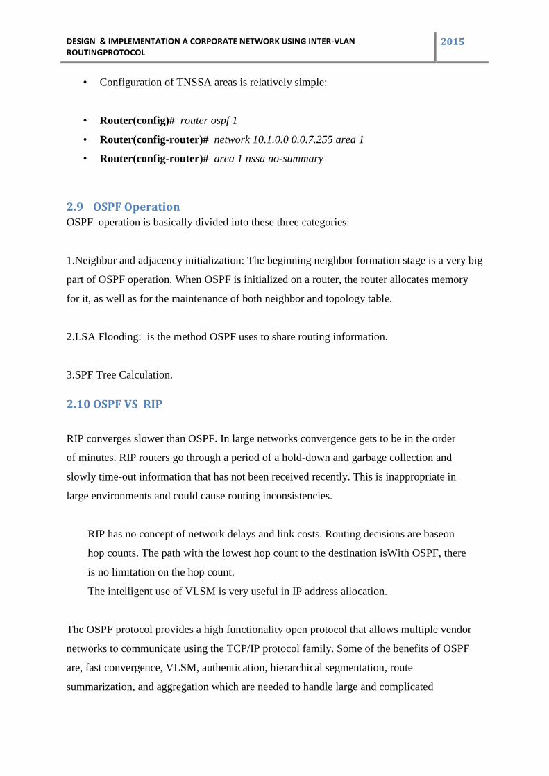
2.9 OSPF Operation OSPF operation is basically divided into these three categories:
1.Neighbor and adjacency initialization: The beginning neighbor formation stage is a very big
part of OSPF operation. When OSPF is initialized on a router, the router allocates memory
for it, as well as for the maintenance of both neighbor and topology table.
2.LSA Flooding: is the method OSPF uses to share routing information.
3.SPF Tree Calculation.
2.10 OSPF VS RIP
RIP converges slower than OSPF. In large networks convergence gets to be in the order
of minutes. RIP routers go through a period of a hold-down and garbage collection and
slowly time-out information that has not been received recently. This is inappropriate in
large environments and could cause routing inconsistencies.
RIP has no concept of network delays and link costs. Routing decisions are baseon
hop counts. The path with the lowest hop count to the destination isWith OSPF, there
is no limitation on the hop count.
The intelligent use of VLSM is very useful in IP address allocation.
The OSPF protocol provides a high functionality open protocol that allows multiple vendor
networks to communicate using the TCP/IP protocol family. Some of the benefits of OSPF
are, fast convergence, VLSM, authentication, hierarchical segmentation, route
summarization, and aggregation which are needed to handle large and complicated
DESIGN & IMPLEMENTATION A CORPORATE NETWORK USING INTER-VLAN ROUTINGPROTOCOL
2015
networks
3 Chapter 3
3.1 Virtual Local Area Network
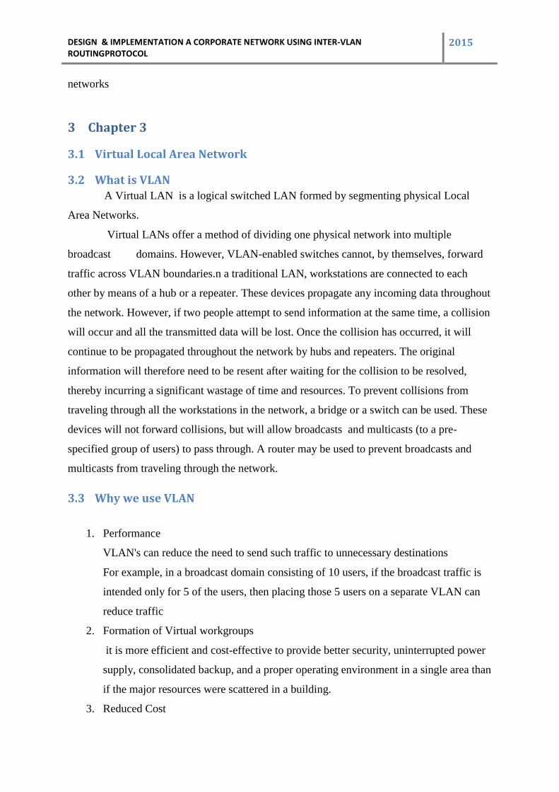
3.2 What is VLAN A Virtual LAN is a logical switched LAN formed by segmenting physical Local
Area Networks.
Virtual LANs offer a method of dividing one physical network into multiple
broadcast domains. However, VLAN-enabled switches cannot, by themselves, forward
traffic across VLAN boundaries.n a traditional LAN, workstations are connected to each
other by means of a hub or a repeater. These devices propagate any incoming data throughout
the network. However, if two people attempt to send information at the same time, a collision
will occur and all the transmitted data will be lost. Once the collision has occurred, it will
continue to be propagated throughout the network by hubs and repeaters. The original
information will therefore need to be resent after waiting for the collision to be resolved,
thereby incurring a significant wastage of time and resources. To prevent collisions from
traveling through all the workstations in the network, a bridge or a switch can be used. These
devices will not forward collisions, but will allow broadcasts and multicasts (to a pre-
specified group of users) to pass through. A router may be used to prevent broadcasts and
multicasts from traveling through the network.
3.3 Why we use VLAN
1. Performance
VLAN's can reduce the need to send such traffic to unnecessary destinations
For example, in a broadcast domain consisting of 10 users, if the broadcast traffic is
intended only for 5 of the users, then placing those 5 users on a separate VLAN can
reduce traffic
2. Formation of Virtual workgroups
it is more efficient and cost-effective to provide better security, uninterrupted power
supply, consolidated backup, and a proper operating environment in a single area than
if the major resources were scattered in a building.
3. Reduced Cost
DESIGN & IMPLEMENTATION A CORPORATE NETWORK USING INTER-VLAN ROUTINGPROTOCOL
2015
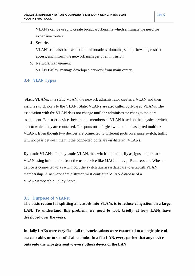
VLAN's can be used to create broadcast domains which eliminate the need for
expensive routers.
4. Security
VLAN's can also be used to control broadcast domains, set up firewalls, restrict
access, and inform the network manager of an intrusion
5. Network management
VLAN Easley manage developed network from main center .
3.4 VLAN Types
Static VLANs: In a static VLAN, the network administrator creates a VLAN and then
assigns switch ports to the VLAN. Static VLANs are also called port-based VLANs. The
association with the VLAN does not change until the administrator changes the port
assignment. End-user devices become the members of VLAN based on the physical switch
port to which they are connected. The ports on a single switch can be assigned multiple
VLANs. Even though two devices are connected to different ports on a same switch, traffic
will not pass between them if the connected ports are on different VLANs.
Dynamic VLANs: In a dynamic VLAN, the switch automatically assigns the port to a
VLAN using information from the user device like MAC address, IP address etc. When a
device is connected to a switch port the switch queries a database to establish VLAN
membership. A network administrator must configure VLAN database of a
VLANMembership Policy Serve
3.5 Purpose of VLANs:
The basic reason for splitting a network into VLANs is to reduce congestion on a large
LAN. To understand this problem, we need to look briefly at how LANs have
developed over the years.
Initially LANs were very flat—all the workstations were connected to a single piece of
coaxial cable, or to sets of chained hubs. In a flat LAN, every packet that any device
puts onto the wire gets sent to every others device of the LAN
DESIGN & IMPLEMENTATION A CORPORATE NETWORK USING INTER-VLAN ROUTINGPROTOCOL
2015
3.6 VLAN Types of links/ports
There are two types of VLAN connection links and they are Access link and Trunk link.
• Access link: An access link is a link that is part of only one VLAN, and normally access
links are for end devices. Any device attached to an access link is unaware of a VLAN
membership. An access-link connection can understand only standard Ethernet frames.
Switches remove any VLAN information from the frame before it is sent to an access-link
device.
• Trunk link: A Trunk link can carry multiple VLAN traffic and normally a trunk link is used
to connect switches to other switches or to routers. To identify the VLAN that a frame
belongs to, Cisco switches support different identification techniques (VLAN Frame
tagging). Our focus for CCNA Routing and Switching examination is on IEEE 802.1Q.
A trunk link is not assigned to a specific VLAN. Many VLAN traffic can be transported
between switches using a single physical trunk link.
DESIGN & IMPLEMENTATION A CORPORATE NETWORK USING INTER-VLAN ROUTINGPROTOCOL
2015
4 Chapter 4
4.1 INTER –VLAN
4.2 What is Inter-VLAN
Inter-VLAN Routing : Hosts in a VLAN live in their own broadcast domain and can
communicate freely. VLANs create network partitioning and traffic separation at layer 2 of
the OSI . By default, only hosts that are members of the same VLAN can communicate. To
change this and allow inter-VLAN communication, you need a router or a layer 3 switch .
Here we used layer 3 switch .
4.3 Inter-VLAN Routing
1. VLANs isolate traffic by design.
2. Inter-VLAN router of some sort required.
3. Inter-VLAN routing should occur in the distribution layer.
4. Multilayer switch is recommended to terminate.
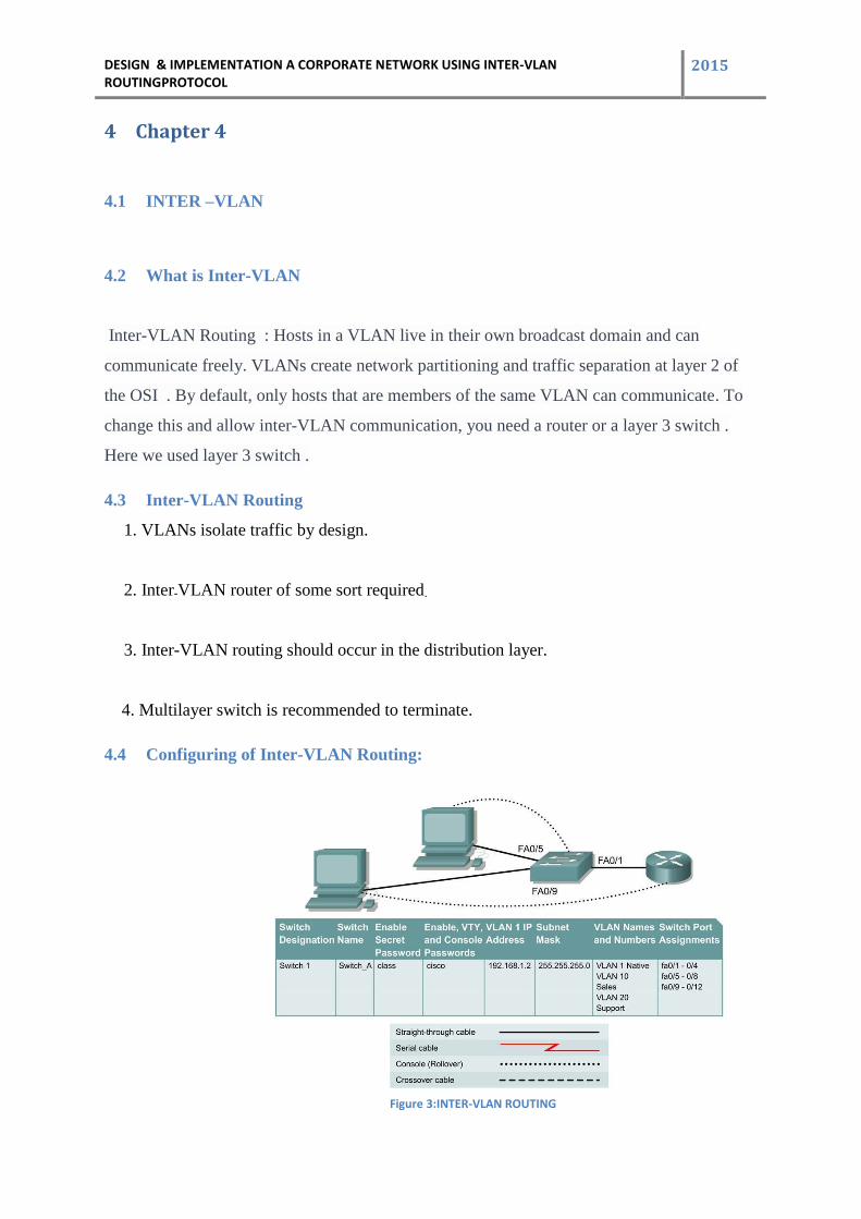
4.4 Configuring of Inter-VLAN Routing:
Figure 3:INTER-VLAN ROUTING
DESIGN & IMPLEMENTATION A CORPORATE NETWORK USING INTER-VLAN ROUTINGPROTOCOL
2015
4.5
Objective
Create a basic switch configuration and verify it.
Create multiple VLANs, name them and assign multiple member ports to them.
Create a basic configuration on a router.
Create an 802.1q trunk line between the switch and router to allow
communication between VLANs.
Basic configuration of Inter-VLAN:
When managing a switch, the Management Domain is always VLAN 1. The Network
Administrator's workstation must have access to a port in the VLAN 1 Management
Domain. All ports are assigned to VLAN 1 by default. This lab will also help demonstrate
how VLANs can be used to separate traffic and reduce broadcast domains.
Cable a network similar to the one in the diagram. The configuration
output used in this lab is produced from a 2950 series switch. Any other switch used may
produce different output.
The following steps are to be executed on each switch unless specifically
instructed otherwise.
Note: The router used must have a Fast Ethernet interface in order to
Support trunking and inter-VLAN routing.
Start a HyperTerminal session.
Note: Go to the erase and reload instructions at the end of this lab.Perform those steps on
all switches in this lab assignment before continuing.
DESIGN & IMPLEMENTATION A CORPORATE NETWORK USING INTER-VLAN ROUTINGPROTOCOL
2015
Step 1 Configure the switch
Configure the hostname, access, and command mode passwords, as well as the management
LAN settings. These values are shown in the chart. If problems occur while performing this
configuration,
refer to the Basic Switch Configuration lab.
Step 2 Configure the hosts attached to the switch
Configure the hosts using the following information. a. For the host
in port 0/5:
IP address 192.168.5.2 Subnet mask
255.255.255.0 Default gateway
192.168.5.1
b. For the host in port 0/9: IP address
192.168.7.2
Subnet mask 255.255.255.0 Default
gateway 192.168.7.1
Step 3 Verify connectivity
Check to see if the hosts can ping the switch.
• Ping the switch IP address from the hosts.
Step 4 Create and name two VLANs
Enter the following commands to create and name two VLANs:
Switch_A#vlan database
Switch_A(vlan)#vlan 10 name Sales
Switch_A(vlan)#vlan 20 name Support
Switch_A(vlan)#exit
DESIGN & IMPLEMENTATION A CORPORATE NETWORK USING INTER-VLAN ROUTINGPROTOCOL
2015
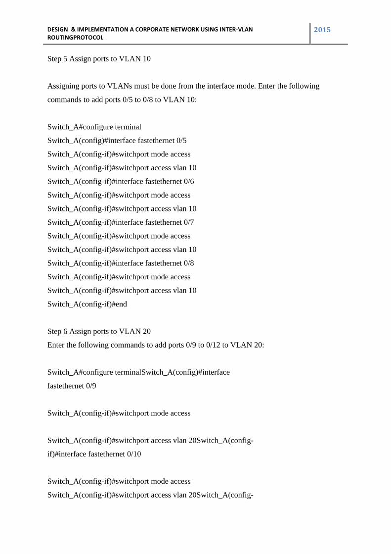
Step 5 Assign ports to VLAN 10
Assigning ports to VLANs must be done from the interface mode. Enter the following
commands to add ports 0/5 to 0/8 to VLAN 10:
Switch_A#configure terminal
Switch_A(config)#interface fastethernet 0/5
Switch_A(config-if)#switchport mode access
Switch_A(config-if)#switchport access vlan 10
Switch_A(config-if)#interface fastethernet 0/6
Switch_A(config-if)#switchport mode access
Switch_A(config-if)#switchport access vlan 10
Switch_A(config-if)#interface fastethernet 0/7
Switch_A(config-if)#switchport mode access
Switch_A(config-if)#switchport access vlan 10
Switch_A(config-if)#interface fastethernet 0/8
Switch_A(config-if)#switchport mode access
Switch_A(config-if)#switchport access vlan 10
Switch_A(config-if)#end
Step 6 Assign ports to VLAN 20
Enter the following commands to add ports 0/9 to 0/12 to VLAN 20:
Switch_A#configure terminalSwitch_A(config)#interface
fastethernet 0/9
Switch_A(config-if)#switchport mode access
Switch_A(config-if)#switchport access vlan 20Switch_A(config-
if)#interface fastethernet 0/10
Switch_A(config-if)#switchport mode access
Switch_A(config-if)#switchport access vlan 20Switch_A(config-
DESIGN & IMPLEMENTATION A CORPORATE NETWORK USING INTER-VLAN ROUTINGPROTOCOL
2015
if)#interface fastethernet 0/11
Switch_A(config-if)#switchport mode access
Switch_A(config-if)#switchport access vlan 20
Switch_A(config-if)#interface fastethernet0/12
Switch_A(config-if)#switchport mode access
Switch_A(config-if)#switchport access vlan 20
Switch_A(config-if)#end
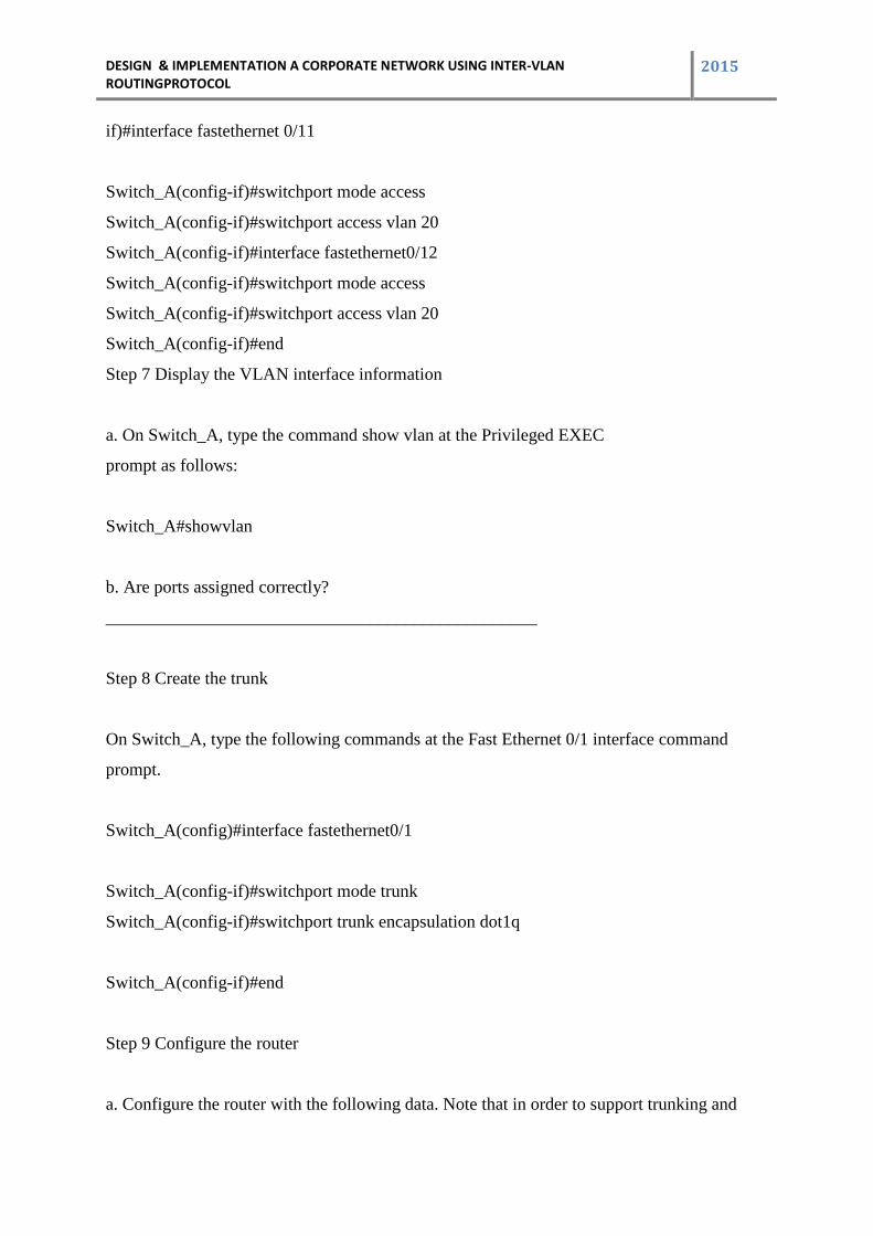
Step 7 Display the VLAN interface information
a. On Switch_A, type the command show vlan at the Privileged EXEC
prompt as follows:
Switch_A#showvlan
b. Are ports assigned correctly?
_________________________________________________
Step 8 Create the trunk
On Switch_A, type the following commands at the Fast Ethernet 0/1 interface command
prompt.
Switch_A(config)#interface fastethernet0/1
Switch_A(config-if)#switchport mode trunk
Switch_A(config-if)#switchport trunk encapsulation dot1q
Switch_A(config-if)#end
Step 9 Configure the router
a. Configure the router with the following data. Note that in order to support trunking and
DESIGN & IMPLEMENTATION A CORPORATE NETWORK USING INTER-VLAN ROUTINGPROTOCOL
2015
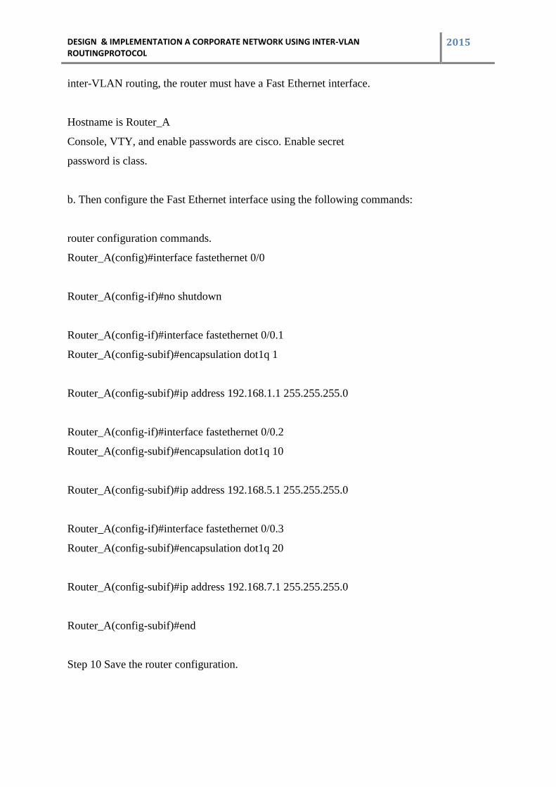
inter-VLAN routing, the router must have a Fast Ethernet interface.
Hostname is Router_A
Console, VTY, and enable passwords are cisco. Enable secret
password is class.
b. Then configure the Fast Ethernet interface using the following commands:
router configuration commands.
Router_A(config)#interface fastethernet 0/0
Router_A(config-if)#no shutdown
Router_A(config-if)#interface fastethernet 0/0.1
Router_A(config-subif)#encapsulation dot1q 1
Router_A(config-subif)#ip address 192.168.1.1 255.255.255.0
Router_A(config-if)#interface fastethernet 0/0.2
Router_A(config-subif)#encapsulation dot1q 10
Router_A(config-subif)#ip address 192.168.5.1 255.255.255.0
Router_A(config-if)#interface fastethernet 0/0.3
Router_A(config-subif)#encapsulation dot1q 20
Router_A(config-subif)#ip address 192.168.7.1 255.255.255.0
Router_A(config-subif)#end
Step 10 Save the router configuration.
DESIGN & IMPLEMENTATION A CORPORATE NETWORK USING INTER-VLAN ROUTINGPROTOCOL
2015
5 Chapter 5
5.1 Structure of Corporate House
5.2 The Basics of Corporate Office Structure
In an attempt to create a corporation where stockholders' interests are looked after, many
firms have implemented a two-tier corporate hierarchy. On the first tier is the board of
governors or directors: these individuals are elected by the shareholders of the corporation.
On the second tier is the upper management: these individuals are hired by the board of
directors.
Board of Directors :
Elected by the shareholders, the board of directors is made up of two types of representatives.
The first type involves individuals chosen from within the company. This can be a CEO,
CFO, manager or any other person who works for the company daily. The other type of
representative is chosen externally and is considered to be independent from the company.
The role of the board is to monitor a corporation's managers, acting as an advocate for
stockholders. In essence, the board of directors tries to make sure that shareholders' interests
are well served.
Board members can be divided into three categories:
Chairman – Technically the leader of the corporation, the board chairman is
responsible for running the board smoothly and effectively. His or her duties typically
include maintaining strong communication with the chief executive officer and high-
level executives, formulating the company's business strategy, representing
management and the board to the general public and shareholders, and maintaining
corporate integrity. A chairman is elected from the board of directors.
Inside Directors – These directors are responsible for approving high-level budgets
prepared by upper management, implementing and monitoring business strategy, and
approving core corporate initiatives and projects. Inside directors are either
shareholders or high-level managers from within the company. Inside directors help
DESIGN & IMPLEMENTATION A CORPORATE NETWORK USING INTER-VLAN ROUTINGPROTOCOL
2015
provide internal perspectives for other board members. These individuals are also
referred to as executive directors if they are part of company's management team.
Outside Directors – While having the same responsibilities as the inside directors in
determining strategic direction and corporate policy, outside directors are different in
that they are not directly part of the management team. The purpose of having outside
directors is to provide unbiased and impartial perspectives on issues brought to the
board.
Management Team:
As the other tier of the company, the management team is directly responsible for the
company's day-to-day operations and profitability.
Chief Executive Officer (CEO) – As the top manager, the CEO is typically responsible
for the corporation's entire operations and reports directly to the chairman and board
of directors. It is the CEO's responsibility to implement board decisions and
initiatives, and to maintain smooth operation of the firm with senior management's
assistance. Often, the CEO will also be designated as the company's president and
therefore be one of the inside directors on the board (if not the chairman). However, it
is highly suggested that a company's CEO should not also be the company's chairman
to ensure the chairman's independence and clear lines of authority.
Chief Operations Officer (COO) – Responsible for the corporation's operations, the
COO looks after issues related to marketing, sales, production and personnel. More
hands-on than the CEO, the COO looks after day-to-day activities while providing
feedback to the CEO. The COO is often referred to as a senior vice president.
Chief Financial Officer (CFO) – Also reporting directly to the CEO, the CFO is
responsible for analyzing and reviewing financial data, reporting financial
performance, preparing budgets and monitoring expenditures and costs. The CFO is
required to present this information to the board of directors at regular intervals and
provide it to shareholders and regulatory bodies such as the Securities and Exchange
Commission (SEC). Also usually referred to as a senior vice president, the CFO
routinely checks the corporation's financial health and integrity.
DESIGN & IMPLEMENTATION A CORPORATE NETWORK USING INTER-VLAN ROUTINGPROTOCOL
2015
The Bottom Line
Together, management and the board of directors have the ultimate goal of maximizing
shareholder value. In theory, management looks after the day-to-day operations, and the
board ensures that shareholders are adequately represented. But the reality is that many
boards consist of management.
When we are researching a company, it's always a good idea to see if there is a good balance
between internal and external board members. Other good signs are the separation of CEO
and chairman roles and a variety of professional expertise on the board from accountants,
lawyers and executives. It's not uncommon to see boards that consist of the current CEO , the
CFO and the COO, along with the retired CEO, family members, etc. This does not
necessarily signal that a company is a bad investment, but as a shareholder, we should
question whether such a corporate structure is in our best interests.
5.3 The Basic Structure of Our Project Corporate House
We structure a corporate office who has 7 main and 7 sub branches in Bangladesh.Every
branch has many departments like as
sales,marketing,admin,research,humanresource,engineering,security,finance,helpdesk,manag
ementetc.And each department has its own switch.Users are grouped physically together and
are connected to their switch.7 main branches has 60 and 7 sub branches has 30 employees
in each department.
DESIGN & IMPLEMENTATION A CORPORATE NETWORK USING INTER-VLAN ROUTINGPROTOCOL
2015
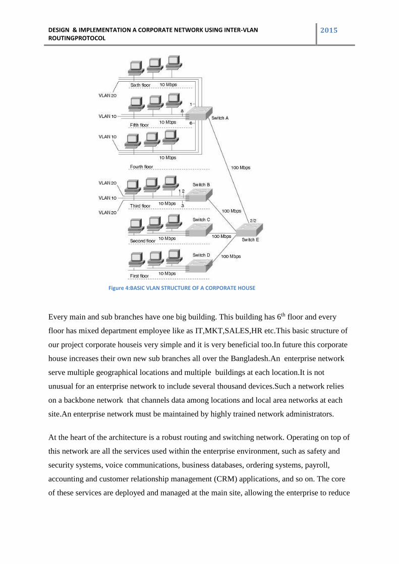
Figure 4:BASIC VLAN STRUCTURE OF A CORPORATE HOUSE
Every main and sub branches have one big building. This building has 6th floor and every
floor has mixed department employee like as IT,MKT,SALES,HR etc.This basic structure of
our project corporate houseis very simple and it is very beneficial too.In future this corporate
house increases their own new sub branches all over the Bangladesh.An enterprise network
serve multiple geographical locations and multiple buildings at each location.It is not
unusual for an enterprise network to include several thousand devices.Such a network relies
on a backbone network that channels data among locations and local area networks at each
site.An enterprise network must be maintained by highly trained network administrators.
At the heart of the architecture is a robust routing and switching network. Operating on top of
this network are all the services used within the enterprise environment, such as safety and
security systems, voice communications, business databases, ordering systems, payroll,
accounting and customer relationship management (CRM) applications, and so on. The core
of these services are deployed and managed at the main site, allowing the enterprise to reduce
DESIGN & IMPLEMENTATION A CORPORATE NETWORK USING INTER-VLAN ROUTINGPROTOCOL
2015
the need for separate services to be operated and maintained at various remote locations.
These centralized systems and applications are served by a data center at the main site.
The network design used for the Medium Enterprise Design Profile is based around the desire
to represent as many medium enterprise environments as possible. To accomplish this, a
modular design is used, represented by sites and buildings of varying sizes. The sites are
made up of one or more buildings of varying sizes where buildings are sized with the
determining factor being the number of users or connections in that building as well as
physical size. Additionally, it is expected that at least half of the network connections will be
wireless.
The main headquarters site and large remote site designs are meant to represent significantly
sized sites containing the largest user populations. The design for the main headquarters site
can accommodate up to six buildings of varying sizes ranging from large to extra small.
The medium remote site design is targeted at enterprise sites that have approximately three
buildings ranging in size from medium to smal
DESIGN & IMPLEMENTATION A CORPORATE NETWORK USING INTER-VLAN ROUTINGPROTOCOL
2015
Chapter 6
6 Design A Network And IP Plan
6.1 Design whole diagram of Project
DESIGN & IMPLEMENTATION A CORPORATE NETWORK USING INTER-VLAN ROUTINGPROTOCOL
2015
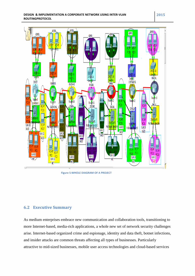
Figure 5:WHOLE DIAGRAM OF A PROJECT
6.2 Executive Summary
As medium enterprises embrace new communication and collaboration tools, transitioning to
more Internet-based, media-rich applications, a whole new set of network security challenges
arise. Internet-based organized crime and espionage, identity and data theft, botnet infections,
and insider attacks are common threats affecting all types of businesses. Particularly
attractive to mid-sized businesses, mobile user access technologies and cloud-based services
DESIGN & IMPLEMENTATION A CORPORATE NETWORK USING INTER-VLAN ROUTINGPROTOCOL
2015
deliver great flexibility and cost-savings, but not without posing new challenges.
Understanding the nature and diversity of all threats affecting medium enterprises, and how
they may evolve over time, is the first step towards a successful security strategy. Although
medium enterprises tend to have fewer locations and employees to protect, tighter budgets
and limited resources require medium enterprises to take an innovative and cost-effective
approach to security. Additionally, the security strategy should be one that helps the medium
enterprise achieve and maintain compliance with the mandated standards and regulations.
Architecture help secure the medium enterprise by building a solid and reliable network
infrastructure that is resilient to both well-known and new forms of attacks. Design
recommendations presented are based on an understanding of the current and future needs of,
and in consideration of the technical and financial constraints often faced by, medium
enterprises.
6.3 Safe Architecture Principles
The SAFE design blueprints were created according to the following architecture principles:
• Defense in depth—Multi-layer security is embedded throughout the entire infrastructure,
endpoints, and applications.
• Global and local intelligence and collaboration—Cloud-based threat information,
reputation-based intelligence, and local event and posture information are shared across
safeguards for greater visibility and control under a common strategy.
• Service availability and resiliency—Multi-level redundancy and device hardening are
included.
• Modularity and flexibility—Functional modular designs for maximum flexibility and
adaptability are provided.
• Operational efficiency—Tools and procedures are provided to verify the effectiveness
and proper operation of safeguards.
• Regulatory compliance—A rich set of security practices and functions commonly
required by regulations and standards are delivered.
DESIGN & IMPLEMENTATION A CORPORATE NETWORK USING INTER-VLAN ROUTINGPROTOCOL
2015
6.4 Underlying Network Design
The SAFE security best practices, designs, and configurations presented in this document
were integrated and validated using the network design for medium enterprises as
documented in the Medium Enterprise Design Profile. The Medium Enterprise Design Profile
is a network architecture that enables medium enterprises to deliver all the services required
for an enhanced business environment. The Medium Enterprise Design Profile includes a
routing and switching LAN foundation and integrates services such as WAN connectivity,
security, unified communications, and mobility.
The Medium Enterprise Design Profile is based on a validated network architecture designed
around both business operations and technical considerations. Because cost is a common
limiting factor to medium enterprise network designs, the architecture topologies and
platforms were carefully selected to increase productivity while reducing overall costs. The
Medium Enterprise Design Profile accommodates a main site and one or more remote sites of
various sizes, interconnected over a metro Ethernet or managed WAN service. Each of these
sites may contain one or more buildings of varying sizes.
6.5 Medium Enterprise Network Security Design
The architecture is designed with built-in security to protect the infrastructure and to provide
a secure online environment for businesses. A series of network security technologies and
products are strategically deployed throughout the network to protect employees and
company assets, to guarantee confidentiality of sensitive data, and to ensure the availability
and integrity of systems and data. Safeguards were carefully chosen to mitigate well-known
attacks as well as emerging threats. Understanding the diverse nature of threats and how they
may evolve over time is the first step towards a successful enterprise security strategy.
The following are some of the common threats to enterprise environments:
• Service disruption—Disruption to the infrastructure, applications, and other business
resources caused by botnets, worms, malware, adware, spyware, viruses, denial-of-service
(DoS) attacks, and Layer 2 attacks
• Network abuse—Use of non-approved applications by employees, peer-to-peer file
sharing and instant messaging abuse, and access to non-business-related content
DESIGN & IMPLEMENTATION A CORPORATE NETWORK USING INTER-VLAN ROUTINGPROTOCOL
2015
• Unauthorized access—Intrusions, unauthorized users, escalation of privileges, IP
spoofing, and unauthorized access to restricted resources
• Data loss—Loss or leakage of private data from servers and endpoints while in transit or
as a result of spyware, malware, key-loggers, viruses, and so on
• Identity theft and fraud—Theft of personal identity or fraud on servers and end users
through phishing and E-mail spam
The medium enterprise network security design focuses on the following key security
elements:
6.6 Network Foundation Protection
Medium enterprise networks are built with routers, switches, and other infrastructure network
devices that keep the applications and services running. These infrastructure devices must be
properly hardened and secured to maintain continued operation and access to these services.
To ensure the availability of the medium enterprise network infrastructure, the security
design leverages the Network Foundation Protection best practices for the following areas
Secure management servers and endpoints with endpoint protection software and operating
system (OS) hardening best practices.
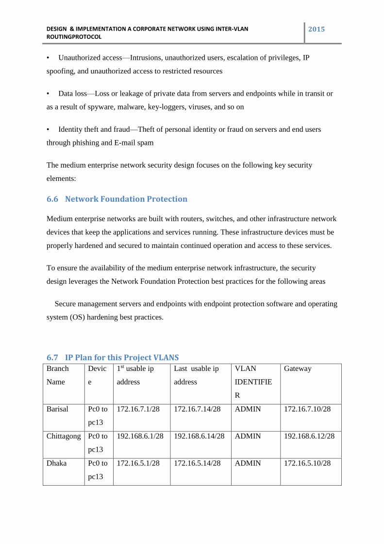
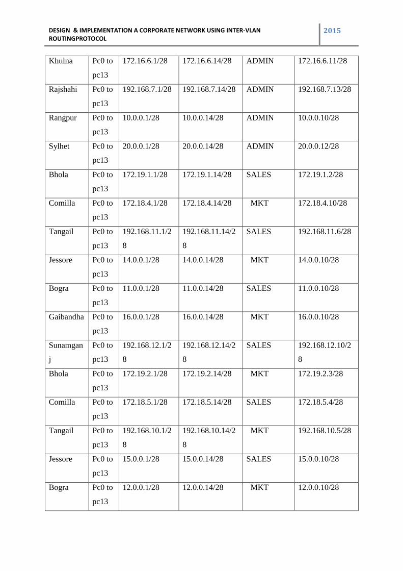
6.7 IP Plan for this Project VLANS
Branch
Name
Devic
e
1st usable ip
address
Last usable ip
address
VLAN
IDENTIFIE
R
Gateway
Barisal Pc0 to
pc13
172.16.7.1/28 172.16.7.14/28 ADMIN 172.16.7.10/28
Chittagong Pc0 to
pc13
192.168.6.1/28 192.168.6.14/28 ADMIN 192.168.6.12/28
Dhaka Pc0 to
pc13
172.16.5.1/28 172.16.5.14/28 ADMIN 172.16.5.10/28
DESIGN & IMPLEMENTATION A CORPORATE NETWORK USING INTER-VLAN ROUTINGPROTOCOL
2015
Khulna Pc0 to
pc13
172.16.6.1/28 172.16.6.14/28 ADMIN 172.16.6.11/28
Rajshahi Pc0 to
pc13
192.168.7.1/28 192.168.7.14/28 ADMIN 192.168.7.13/28
Rangpur Pc0 to
pc13
10.0.0.1/28 10.0.0.14/28 ADMIN 10.0.0.10/28
Sylhet Pc0 to
pc13
20.0.0.1/28 20.0.0.14/28 ADMIN 20.0.0.12/28
Bhola Pc0 to
pc13
172.19.1.1/28 172.19.1.14/28 SALES 172.19.1.2/28
Comilla Pc0 to
pc13
172.18.4.1/28 172.18.4.14/28 MKT 172.18.4.10/28
Tangail Pc0 to
pc13
192.168.11.1/2
8
192.168.11.14/2
8
SALES 192.168.11.6/28
Jessore Pc0 to
pc13
14.0.0.1/28 14.0.0.14/28 MKT 14.0.0.10/28
Bogra Pc0 to
pc13
11.0.0.1/28 11.0.0.14/28 SALES 11.0.0.10/28
Gaibandha Pc0 to
pc13
16.0.0.1/28 16.0.0.14/28 MKT 16.0.0.10/28
Sunamgan
j
Pc0 to
pc13
192.168.12.1/2
8
192.168.12.14/2
8
SALES 192.168.12.10/2
8
Bhola Pc0 to
pc13
172.19.2.1/28 172.19.2.14/28 MKT 172.19.2.3/28
Comilla Pc0 to
pc13
172.18.5.1/28 172.18.5.14/28 SALES 172.18.5.4/28
Tangail Pc0 to
pc13
192.168.10.1/2
8
192.168.10.14/2
8
MKT 192.168.10.5/28
Jessore Pc0 to
pc13
15.0.0.1/28 15.0.0.14/28 SALES 15.0.0.10/28
Bogra Pc0 to
pc13
12.0.0.1/28 12.0.0.14/28 MKT 12.0.0.10/28

DESIGN & IMPLEMENTATION A CORPORATE NETWORK USING INTER-VLAN ROUTINGPROTOCOL
2015
Gaibandha Pc0 to
pc13
17.0.0.1/28 17.0.0.14/28 SALES 17.0.0.10/28
Sunamgan
j
Pc0 to
pc13
192.168.13.1/2
8
192.168.13.14/2
8
MKT 192.168.13.10/2
8
Table 1:IPPlaning for this Project
DESIGN & IMPLEMENTATION A CORPORATE NETWORK USING INTER-VLAN ROUTINGPROTOCOL
2015
7 Chapter 5
7.1 Implementation of Inter-VLAN Communication
Currently, in every department of this company 253 employees can work highest. OSPF has
been used to work in this big network. OSPF can configure in any router easily and in this
kind of big network, OSPF is a proven system to work fast. After all, company configure
separate VLAN for every department so that the important files and information for a
selected department can’t deliver to another department. After establishing this VLAN, the
network security has been increased minimum x3 times better.
In every department, Inter-VLAN routing configure has been completed so that one
employee can communicate with another from own department/another department or district
in emergency purpose. We can communicate with higher security from one branch to another
one which is far from the communicator branch. Moreover, as the number of the domain is
decreased, no data loss of any communication or any kind of error don’t happened.
We hope that by using this Inter-VLAN routing system, the company can spread its branch
and sub branches all over the Bangladesh.
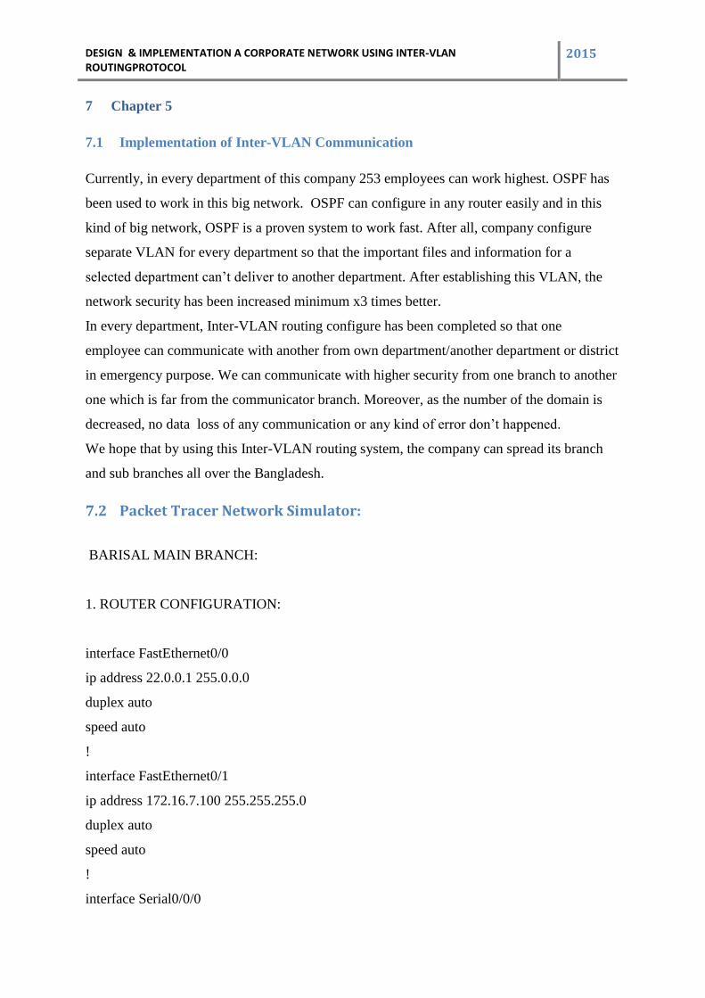
7.2 Packet Tracer Network Simulator:
BARISAL MAIN BRANCH:
1. ROUTER CONFIGURATION:
interface FastEthernet0/0
ip address 22.0.0.1 255.0.0.0
duplex auto
speed auto
!
interface FastEthernet0/1
ip address 172.16.7.100 255.255.255.0
duplex auto
speed auto
!
interface Serial0/0/0
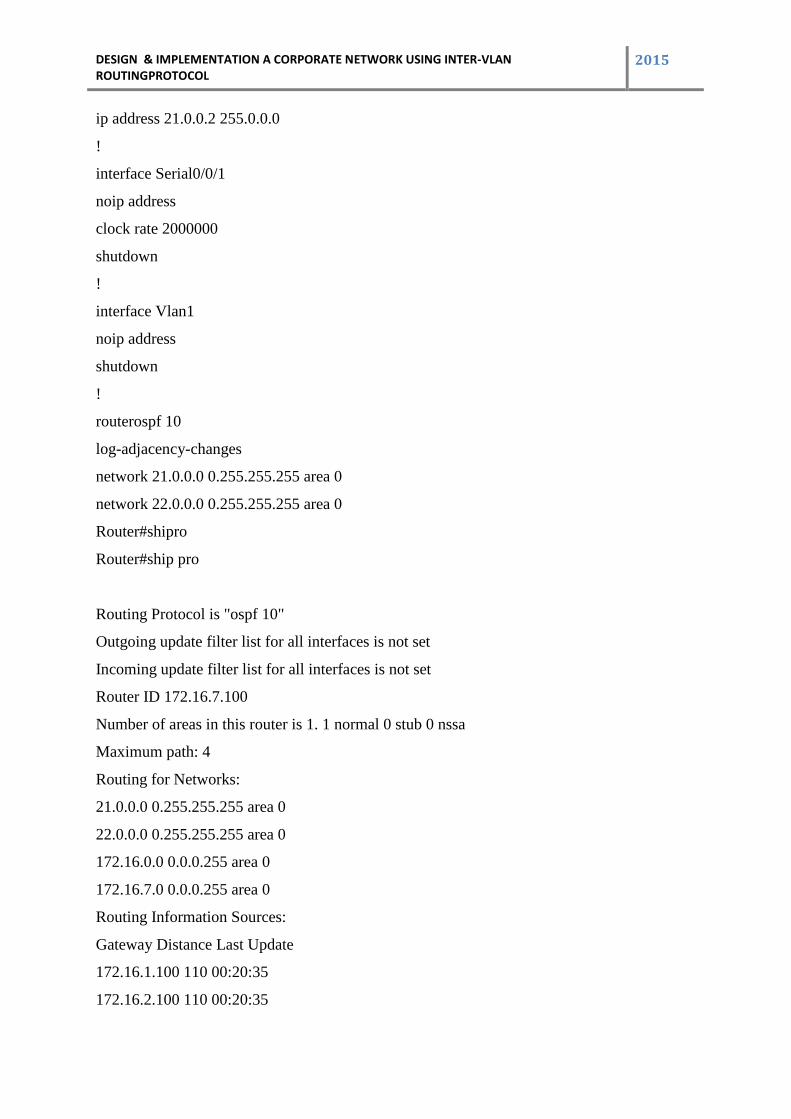
DESIGN & IMPLEMENTATION A CORPORATE NETWORK USING INTER-VLAN ROUTINGPROTOCOL
2015
ip address 21.0.0.2 255.0.0.0
!
interface Serial0/0/1
noip address
clock rate 2000000
shutdown
!
interface Vlan1
noip address
shutdown
!
routerospf 10
log-adjacency-changes
network 21.0.0.0 0.255.255.255 area 0
network 22.0.0.0 0.255.255.255 area 0
Router#shipro
Router#ship pro
Routing Protocol is "ospf 10"
Outgoing update filter list for all interfaces is not set
Incoming update filter list for all interfaces is not set
Router ID 172.16.7.100
Number of areas in this router is 1. 1 normal 0 stub 0 nssa
Maximum path: 4
Routing for Networks:
21.0.0.0 0.255.255.255 area 0
22.0.0.0 0.255.255.255 area 0
172.16.0.0 0.0.0.255 area 0
172.16.7.0 0.0.0.255 area 0
Routing Information Sources:
Gateway Distance Last Update
172.16.1.100 110 00:20:35
172.16.2.100 110 00:20:35
DESIGN & IMPLEMENTATION A CORPORATE NETWORK USING INTER-VLAN ROUTINGPROTOCOL
2015
172.16.3.100 110 00:20:38
172.16.4.100 110 00:20:39
172.16.5.100 110 00:20:35
172.16.6.100 110 00:20:40
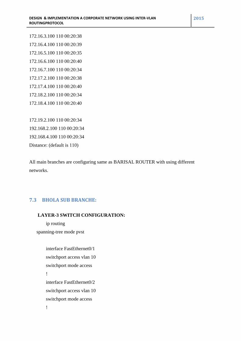
172.16.7.100 110 00:20:34
172.17.2.100 110 00:20:38
172.17.4.100 110 00:20:40
172.18.2.100 110 00:20:34
172.18.4.100 110 00:20:40
172.19.2.100 110 00:20:34
192.168.2.100 110 00:20:34
192.168.4.100 110 00:20:34
Distance: (default is 110)
All main branches are configuring same as BARISAL ROUTER with using different
networks.
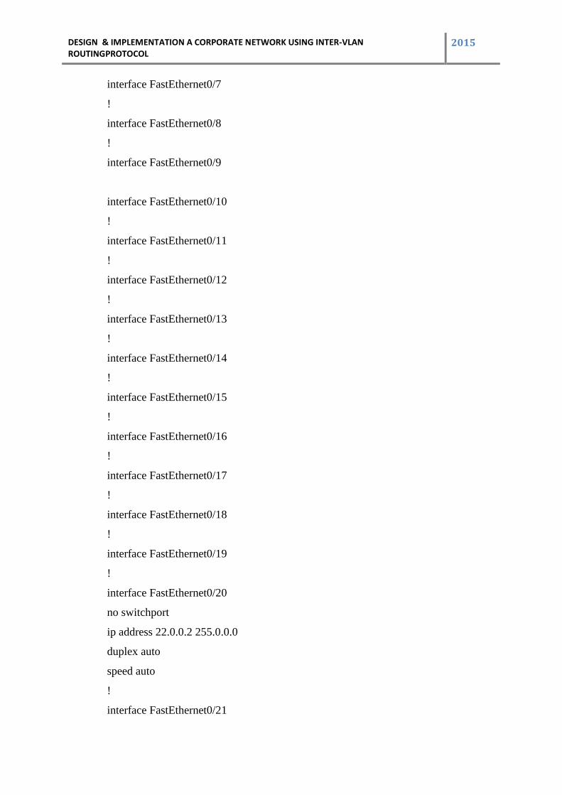
7.3 BHOLA SUB BRANCHE:
LAYER-3 SWITCH CONFIGURATION:
ip routing
spanning-tree mode pvst
interface FastEthernet0/1
switchport access vlan 10
switchport mode access
!
interface FastEthernet0/2
switchport access vlan 10
switchport mode access
!
DESIGN & IMPLEMENTATION A CORPORATE NETWORK USING INTER-VLAN ROUTINGPROTOCOL
2015
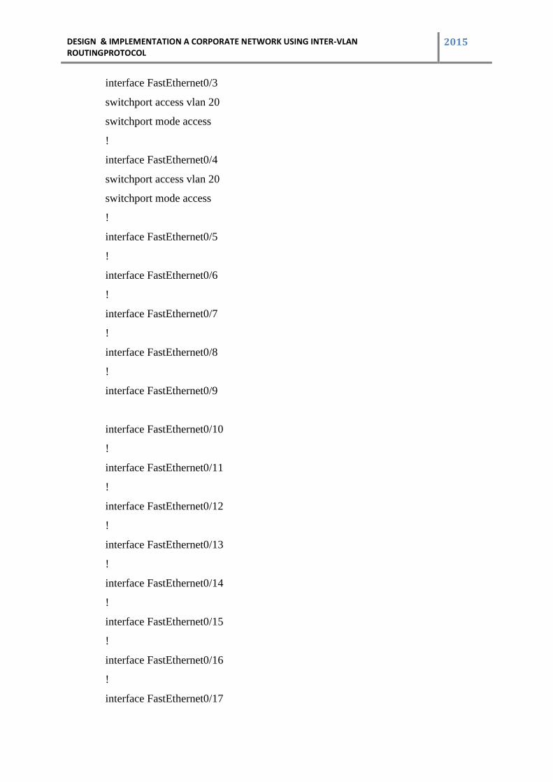
interface FastEthernet0/3
switchport access vlan 20
switchport mode access
!
interface FastEthernet0/4
switchport access vlan 20
switchport mode access
!
interface FastEthernet0/5
!
interface FastEthernet0/6
!
interface FastEthernet0/7
!
interface FastEthernet0/8
!
interface FastEthernet0/9
interface FastEthernet0/10
!
interface FastEthernet0/11
!
interface FastEthernet0/12
!
interface FastEthernet0/13
!
interface FastEthernet0/14
!
interface FastEthernet0/15
!
interface FastEthernet0/16
!
interface FastEthernet0/17
DESIGN & IMPLEMENTATION A CORPORATE NETWORK USING INTER-VLAN ROUTINGPROTOCOL
2015
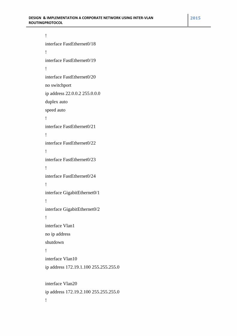
!
interface FastEthernet0/18
!
interface FastEthernet0/19
!
interface FastEthernet0/20
no switchport
ip address 22.0.0.2 255.0.0.0
duplex auto
speed auto
!
interface FastEthernet0/21
!
interface FastEthernet0/22
!
interface FastEthernet0/23
!
interface FastEthernet0/24
!
interface GigabitEthernet0/1
!
interface GigabitEthernet0/2
!
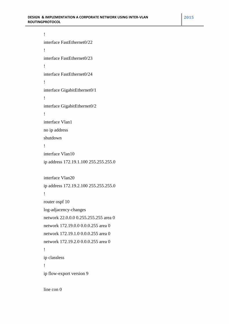
interface Vlan1
no ip address
shutdown
!
interface Vlan10
ip address 172.19.1.100 255.255.255.0
interface Vlan20
ip address 172.19.2.100 255.255.255.0
!
DESIGN & IMPLEMENTATION A CORPORATE NETWORK USING INTER-VLAN ROUTINGPROTOCOL
2015
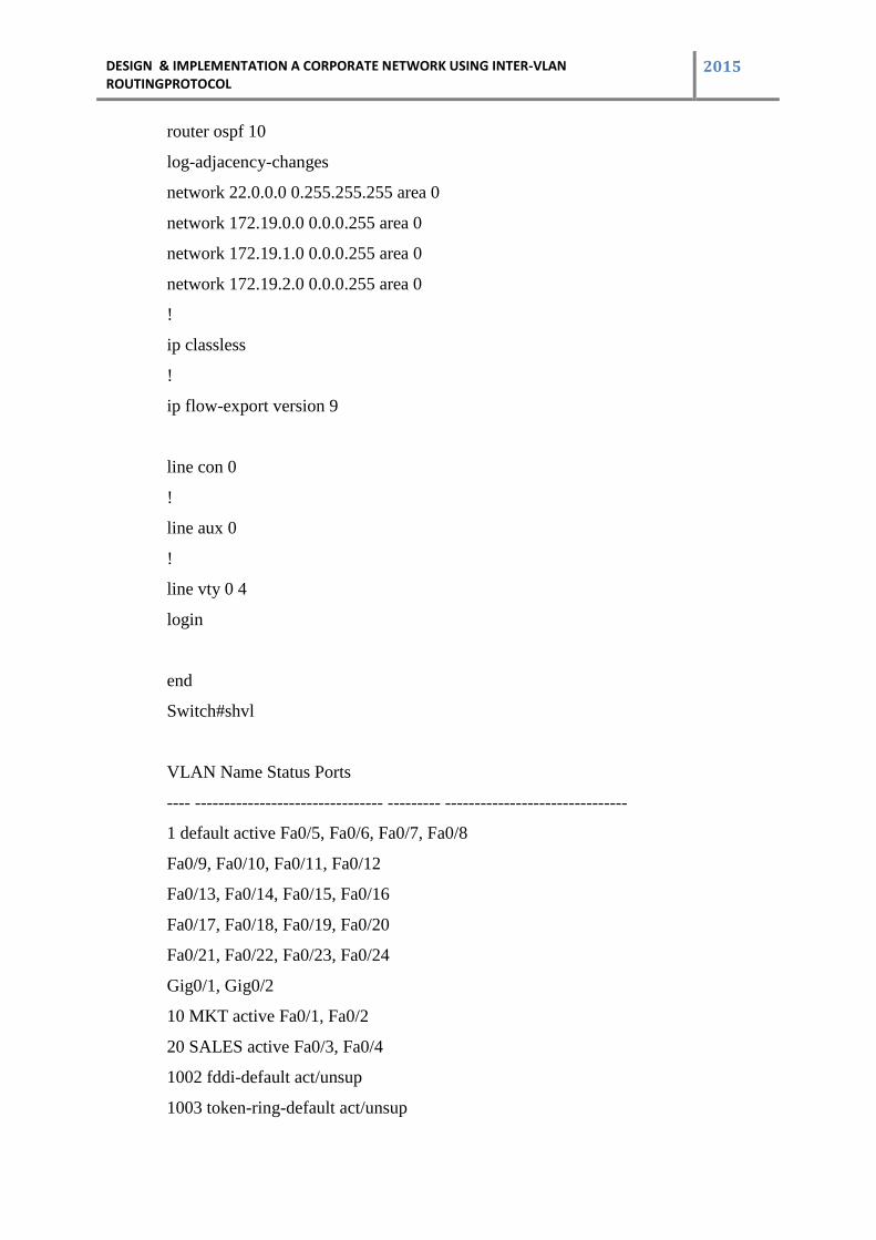
router ospf 10
log-adjacency-changes
network 22.0.0.0 0.255.255.255 area 0
network 172.19.0.0 0.0.0.255 area 0
network 172.19.1.0 0.0.0.255 area 0
network 172.19.2.0 0.0.0.255 area 0
!
ip classless
!
ip flow-export version 9
line con 0
!
line aux 0
!
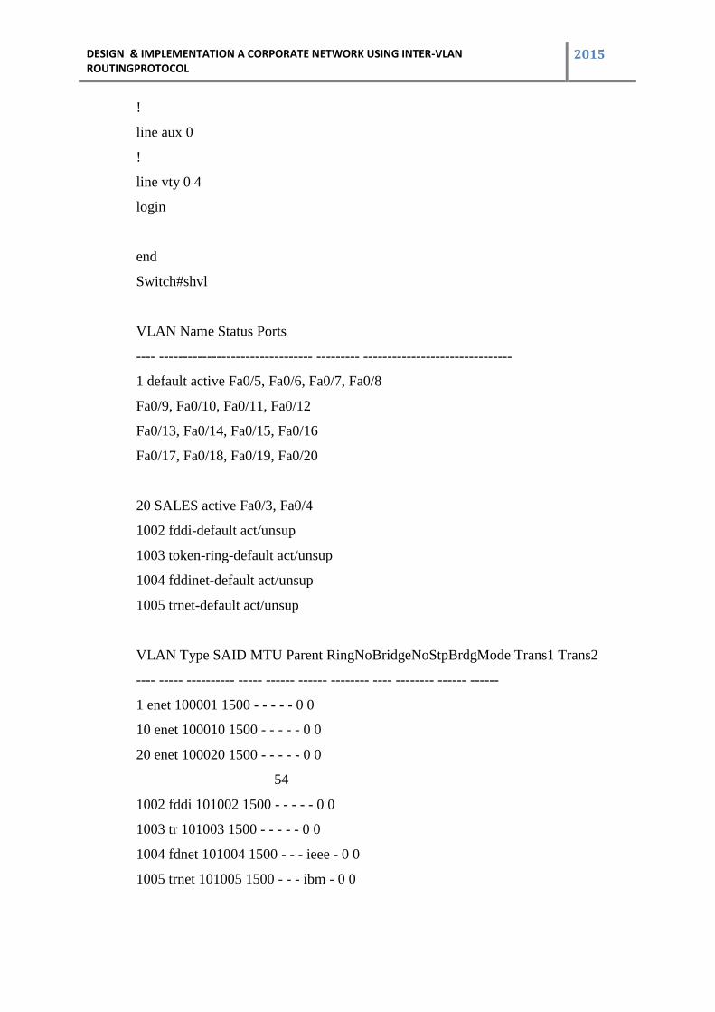
line vty 0 4
login
end
Switch#shvl
VLAN Name Status Ports
---- -------------------------------- --------- -------------------------------
1 default active Fa0/5, Fa0/6, Fa0/7, Fa0/8
Fa0/9, Fa0/10, Fa0/11, Fa0/12
Fa0/13, Fa0/14, Fa0/15, Fa0/16
Fa0/17, Fa0/18, Fa0/19, Fa0/20
Fa0/21, Fa0/22, Fa0/23, Fa0/24
Gig0/1, Gig0/2
10 MKT active Fa0/1, Fa0/2
20 SALES active Fa0/3, Fa0/4
1002 fddi-default act/unsup
1003 token-ring-default act/unsup
DESIGN & IMPLEMENTATION A CORPORATE NETWORK USING INTER-VLAN ROUTINGPROTOCOL
2015
1004 fddinet-default act/unsup
1005 trnet-default act/unsup
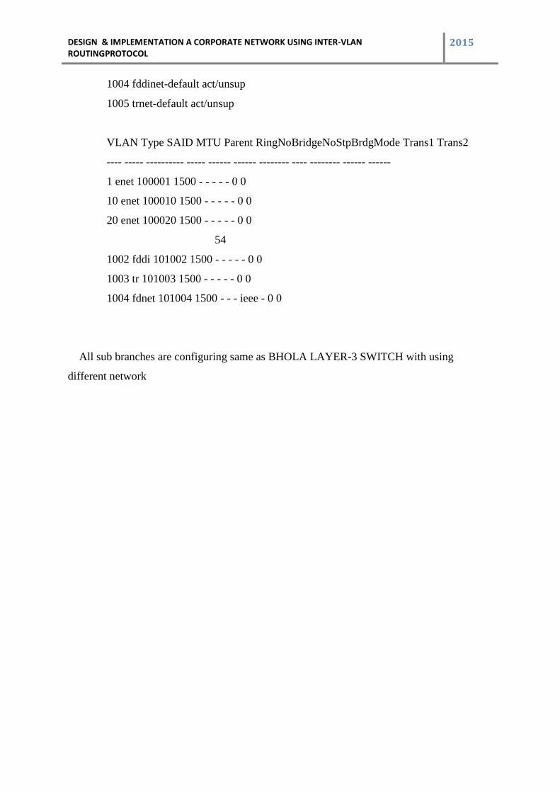
VLAN Type SAID MTU Parent RingNoBridgeNoStpBrdgMode Trans1 Trans2
---- ----- ---------- ----- ------ ------ -------- ---- -------- ------ ------
1 enet 100001 1500 - - - - - 0 0
10 enet 100010 1500 - - - - - 0 0
20 enet 100020 1500 - - - - - 0 0
54
1002 fddi 101002 1500 - - - - - 0 0
1003 tr 101003 1500 - - - - - 0 0
1004 fdnet 101004 1500 - - - ieee - 0 0
All sub branches are configuring same as BHOLA LAYER-3 SWITCH with using
different network
DESIGN & IMPLEMENTATION A CORPORATE NETWORK USING INTER-VLAN ROUTINGPROTOCOL
2015
8 Chapter 8
8.1 Result & Output
8.2 Simulation Results
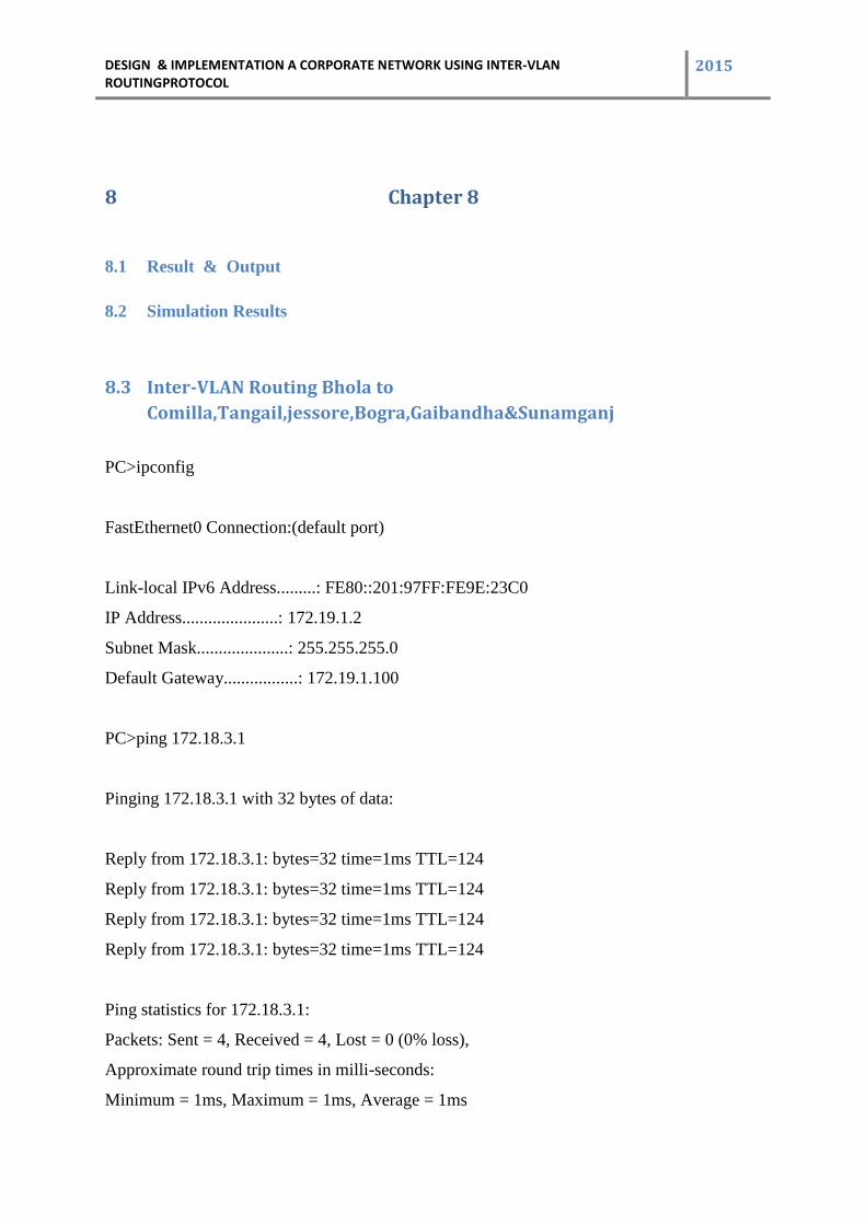
8.3 Inter-VLAN Routing Bhola to
Comilla,Tangail,jessore,Bogra,Gaibandha&Sunamganj
PC>ipconfig
FastEthernet0 Connection:(default port)
Link-local IPv6 Address.........: FE80::201:97FF:FE9E:23C0
IP Address......................: 172.19.1.2
Subnet Mask.....................: 255.255.255.0
Default Gateway.................: 172.19.1.100
PC>ping 172.18.3.1
Pinging 172.18.3.1 with 32 bytes of data:
Reply from 172.18.3.1: bytes=32 time=1ms TTL=124
Reply from 172.18.3.1: bytes=32 time=1ms TTL=124
Reply from 172.18.3.1: bytes=32 time=1ms TTL=124
Reply from 172.18.3.1: bytes=32 time=1ms TTL=124
Ping statistics for 172.18.3.1:
Packets: Sent = 4, Received = 4, Lost = 0 (0% loss),
Approximate round trip times in milli-seconds:
Minimum = 1ms, Maximum = 1ms, Average = 1ms
DESIGN & IMPLEMENTATION A CORPORATE NETWORK USING INTER-VLAN ROUTINGPROTOCOL
2015
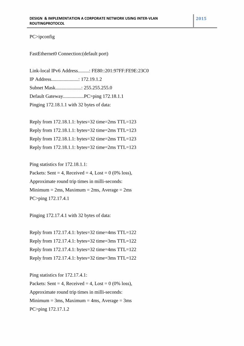
PC>ipconfig
FastEthernet0 Connection:(default port)
Link-local IPv6 Address.........: FE80::201:97FF:FE9E:23C0
IP Address......................: 172.19.1.2
Subnet Mask.....................: 255.255.255.0
Default Gateway.................PC>ping 172.18.1.1
Pinging 172.18.1.1 with 32 bytes of data:
Reply from 172.18.1.1: bytes=32 time=2ms TTL=123
Reply from 172.18.1.1: bytes=32 time=2ms TTL=123
Reply from 172.18.1.1: bytes=32 time=2ms TTL=123
Reply from 172.18.1.1: bytes=32 time=2ms TTL=123
Ping statistics for 172.18.1.1:
Packets: Sent = 4, Received = 4, Lost = 0 (0% loss),
Approximate round trip times in milli-seconds:
Minimum = 2ms, Maximum = 2ms, Average = 2ms
PC>ping 172.17.4.1
Pinging 172.17.4.1 with 32 bytes of data:
Reply from 172.17.4.1: bytes=32 time=4ms TTL=122
Reply from 172.17.4.1: bytes=32 time=3ms TTL=122
Reply from 172.17.4.1: bytes=32 time=4ms TTL=122
Reply from 172.17.4.1: bytes=32 time=3ms TTL=122
Ping statistics for 172.17.4.1:
Packets: Sent = 4, Received = 4, Lost = 0 (0% loss),
Approximate round trip times in milli-seconds:
Minimum = 3ms, Maximum = 4ms, Average = 3ms
PC>ping 172.17.1.2
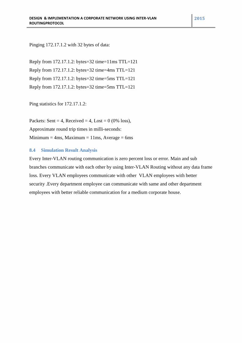
DESIGN & IMPLEMENTATION A CORPORATE NETWORK USING INTER-VLAN ROUTINGPROTOCOL
2015
Pinging 172.17.1.2 with 32 bytes of data:
Reply from 172.17.1.2: bytes=32 time=11ms TTL=121
Reply from 172.17.1.2: bytes=32 time=4ms TTL=121
Reply from 172.17.1.2: bytes=32 time=5ms TTL=121
Reply from 172.17.1.2: bytes=32 time=5ms TTL=121
Ping statistics for 172.17.1.2:
Packets: Sent = 4, Received = 4, Lost = 0 (0% loss),
Approximate round trip times in milli-seconds:
Minimum = 4ms, Maximum = 11ms, Average = 6ms
8.4 Simulation Result Analysis
Every Inter-VLAN routing communication is zero percent loss or error. Main and sub
branches communicate with each other by using Inter-VLAN Routing without any data frame
loss. Every VLAN employees communicate with other VLAN employees with better
security .Every department employee can communicate with same and other department
employees with better reliable communication for a medium corporate house.
DESIGN & IMPLEMENTATION A CORPORATE NETWORK USING INTER-VLAN ROUTINGPROTOCOL
2015
9 Chapter 9
9.1 Conclusion
In this paper I tried to find a suitable inter-vlan with OSPF routing protocol for my
office or company network topology which is useful for real time communication .In real
time communication there are few very important parameters that make it hard for normal
packet based network to give as acceptable QOS .These parameters are End to End delay
,link failure condition and throughput.
The OSPF protocol provides a high functionality open protocol that allows multiple vendor
networks to communicate using the TCP/IP protocol family. Some of the benefits of OSPF
are, fast convergence, VLSM, authentication, hierarchical segmentation, route
summarization, and aggregation which are needed to handle large and complicated
networks.
The basic reason for splitting a network into VLANs is to reduce congestion on a large LAN.
To understand this problem, we need to look briefly at how LANs have developed over the
years.
Initially LANs were very flat—all the workstations were connected to a single piece of
coaxial cable, or to sets of chained hubs. In a flat LAN, every packet that any device puts
onto the wire gets sent to every other device on the LAN.
As the number of workstations on the typical LAN grew, they started to become hopelessly
congested; there were just too many collisions, because most of the time when a workstation
tried to send a packet, it would find that the wire was already occupied by a packet sent by
some other device.
9.2 Future Work Scope
As for future work ,more realistic network topologies and routing polices can be employed
to simulate genuine behavior of the internet .Additional features ,such as route flap damping
,policy routing, and multiprotocol extension and evaluate new technologies that are based on
the multiprotocol extension ,such as OSPF,VPN, Gateway to gateway inter-vlan routing.
The only varying parameter in our analysis, other than routing protocol of course, was the
size of the network topology. Improvement or future works for this project can include
adding metrics on interfaces such as cost, bandwidth, distance, Bit Error Rate (BER), and
delay. Furthermore, various network topologies (in terms of size, routers and links used) can
DESIGN & IMPLEMENTATION A CORPORATE NETWORK USING INTER-VLAN ROUTINGPROTOCOL
2015
be implemented for comparison of performance between these routing protocols. Since
OSPF is the most complex routing protocol, more time could be spent on analyzing it to find
the value of parameters that need to be set in order for it to perform optimally. Another
possibility is to implement real network topologies used, perhaps in a university campus a
company office, or a larger network size while also modifying the network parameters, such
as interfaces, to those of the actual scenario being analyzed.
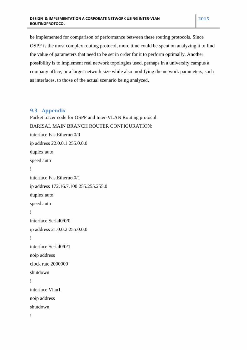
9.3 Appendix Packet tracer code for OSPF and Inter-VLAN Routing protocol:
BARISAL MAIN BRANCH ROUTER CONFIGURATION:
interface FastEthernet0/0
ip address 22.0.0.1 255.0.0.0
duplex auto
speed auto
!
interface FastEthernet0/1
ip address 172.16.7.100 255.255.255.0
duplex auto
speed auto
!
interface Serial0/0/0
ip address 21.0.0.2 255.0.0.0
!
interface Serial0/0/1
noip address
clock rate 2000000
shutdown
!
interface Vlan1
noip address
shutdown
!
DESIGN & IMPLEMENTATION A CORPORATE NETWORK USING INTER-VLAN ROUTINGPROTOCOL
2015
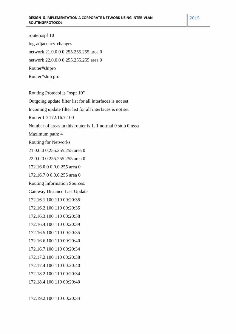
routerospf 10
log-adjacency-changes
network 21.0.0.0 0.255.255.255 area 0
network 22.0.0.0 0.255.255.255 area 0
Router#shipro
Router#ship pro
Routing Protocol is "ospf 10"
Outgoing update filter list for all interfaces is not set
Incoming update filter list for all interfaces is not set
Router ID 172.16.7.100
Number of areas in this router is 1. 1 normal 0 stub 0 nssa
Maximum path: 4
Routing for Networks:
21.0.0.0 0.255.255.255 area 0
22.0.0.0 0.255.255.255 area 0
172.16.0.0 0.0.0.255 area 0
172.16.7.0 0.0.0.255 area 0
Routing Information Sources:
Gateway Distance Last Update
172.16.1.100 110 00:20:35
172.16.2.100 110 00:20:35
172.16.3.100 110 00:20:38
172.16.4.100 110 00:20:39
172.16.5.100 110 00:20:35
172.16.6.100 110 00:20:40
172.16.7.100 110 00:20:34
172.17.2.100 110 00:20:38
172.17.4.100 110 00:20:40
172.18.2.100 110 00:20:34
172.18.4.100 110 00:20:40
172.19.2.100 110 00:20:34
DESIGN & IMPLEMENTATION A CORPORATE NETWORK USING INTER-VLAN ROUTINGPROTOCOL
2015
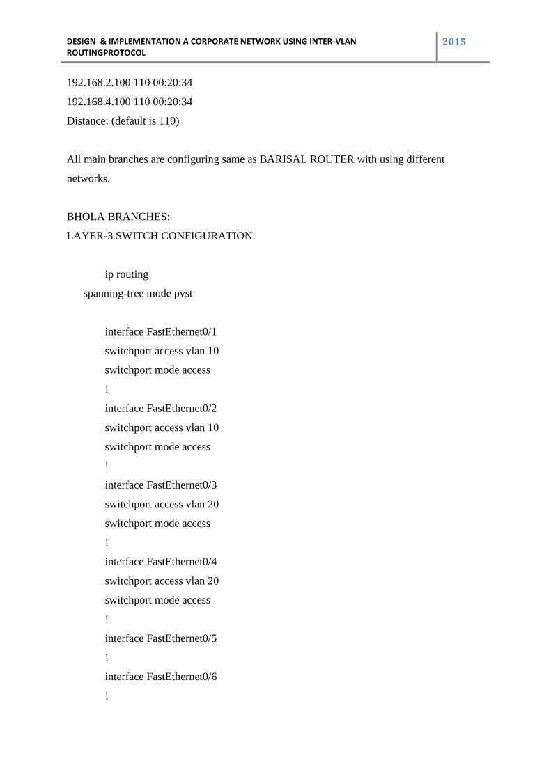
192.168.2.100 110 00:20:34
192.168.4.100 110 00:20:34
Distance: (default is 110)
All main branches are configuring same as BARISAL ROUTER with using different
networks.
BHOLA BRANCHES:
LAYER-3 SWITCH CONFIGURATION:
ip routing
spanning-tree mode pvst
interface FastEthernet0/1
switchport access vlan 10
switchport mode access
!
interface FastEthernet0/2
switchport access vlan 10
switchport mode access
!
interface FastEthernet0/3
switchport access vlan 20
switchport mode access
!
interface FastEthernet0/4
switchport access vlan 20
switchport mode access
!
interface FastEthernet0/5
!
interface FastEthernet0/6
!
DESIGN & IMPLEMENTATION A CORPORATE NETWORK USING INTER-VLAN ROUTINGPROTOCOL
2015
interface FastEthernet0/7
!
interface FastEthernet0/8
!
interface FastEthernet0/9
interface FastEthernet0/10
!
interface FastEthernet0/11
!
interface FastEthernet0/12
!
interface FastEthernet0/13
!
interface FastEthernet0/14
!
interface FastEthernet0/15
!
interface FastEthernet0/16
!
interface FastEthernet0/17
!
interface FastEthernet0/18
!
interface FastEthernet0/19
!
interface FastEthernet0/20
no switchport
ip address 22.0.0.2 255.0.0.0
duplex auto
speed auto
!
interface FastEthernet0/21
DESIGN & IMPLEMENTATION A CORPORATE NETWORK USING INTER-VLAN ROUTINGPROTOCOL
2015
!
interface FastEthernet0/22
!
interface FastEthernet0/23
!
interface FastEthernet0/24
!
interface GigabitEthernet0/1
!
interface GigabitEthernet0/2
!
interface Vlan1
no ip address
shutdown
!
interface Vlan10
ip address 172.19.1.100 255.255.255.0
interface Vlan20
ip address 172.19.2.100 255.255.255.0
!
router ospf 10
log-adjacency-changes
network 22.0.0.0 0.255.255.255 area 0
network 172.19.0.0 0.0.0.255 area 0
network 172.19.1.0 0.0.0.255 area 0
network 172.19.2.0 0.0.0.255 area 0
!
ip classless
!
ip flow-export version 9
line con 0
DESIGN & IMPLEMENTATION A CORPORATE NETWORK USING INTER-VLAN ROUTINGPROTOCOL
2015
!
line aux 0
!
line vty 0 4
login
end
Switch#shvl
VLAN Name Status Ports
---- -------------------------------- --------- -------------------------------
1 default active Fa0/5, Fa0/6, Fa0/7, Fa0/8
Fa0/9, Fa0/10, Fa0/11, Fa0/12
Fa0/13, Fa0/14, Fa0/15, Fa0/16
Fa0/17, Fa0/18, Fa0/19, Fa0/20
20 SALES active Fa0/3, Fa0/4
1002 fddi-default act/unsup
1003 token-ring-default act/unsup
1004 fddinet-default act/unsup
1005 trnet-default act/unsup
VLAN Type SAID MTU Parent RingNoBridgeNoStpBrdgMode Trans1 Trans2
---- ----- ---------- ----- ------ ------ -------- ---- -------- ------ ------
1 enet 100001 1500 - - - - - 0 0
10 enet 100010 1500 - - - - - 0 0
20 enet 100020 1500 - - - - - 0 0
54
1002 fddi 101002 1500 - - - - - 0 0
1003 tr 101003 1500 - - - - - 0 0
1004 fdnet 101004 1500 - - - ieee - 0 0
1005 trnet 101005 1500 - - - ibm - 0 0
DESIGN & IMPLEMENTATION A CORPORATE NETWORK USING INTER-VLAN ROUTINGPROTOCOL
2015
Remote SPAN VLANs
All sub branches are configuring same as BHOLA LAYER-3 SWITCH with using different
networks.
9.4 Reference
1.Cisco CCNP Route 642-902 Quick Reference
2.MaciejWojciechowski , thesis _ bgpsim
3.CCNP ROUTE EXAM 300-101
4.CCNP SWITCH EXAM 300-115
5.CISCO CCNA ROUTING AND SWITCHING EXAM 01-101,EXAM 200-
101,EXAM 200-120
6. IEEE 802.1Q-2011, 1. Overview
7.IEEE 802.1Q-2011, 1.4 VLAN aims and benefits
8."Engineering - Discovery Publication" (PDF). Discovery Institute
9.Amies A, Wu C F, Wang G C, Criveti M (2012)
10.Sincoskie, WD (2002)
11.W. D. Sincoskie and C. J. Cotton
12.Allan, David; Bragg, Nigel (2012)