design kit - cybernet.co.jp kit. dc motor speed control circuit. ... the simulation of dc motor...
TRANSCRIPT

Design KitDC Motor Speed Control Circuit
All Rights Reserved Copyright (C) Bee Technologies Inc. 2010 1
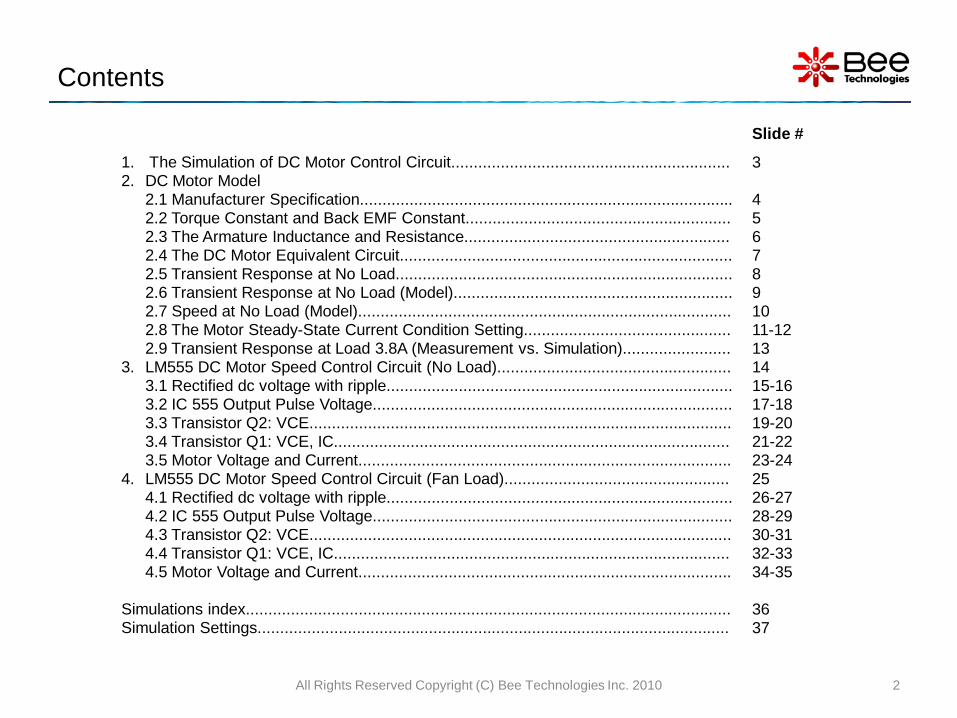
Contents
Slide #
1. The Simulation of DC Motor Control Circuit..............................................................2. DC Motor Model
2.1 Manufacturer Specification...................................................................................2.2 Torque Constant and Back EMF Constant...........................................................2.3 The Armature Inductance and Resistance...........................................................2.4 The DC Motor Equivalent Circuit..........................................................................2.5 Transient Response at No Load...........................................................................2.6 Transient Response at No Load (Model)..............................................................2.7 Speed at No Load (Model)...................................................................................2.8 The Motor Steady-State Current Condition Setting..............................................2.9 Transient Response at Load 3.8A (Measurement vs. Simulation)........................
3. LM555 DC Motor Speed Control Circuit (No Load)....................................................3.1 Rectified dc voltage with ripple.............................................................................3.2 IC 555 Output Pulse Voltage................................................................................3.3 Transistor Q2: VCE..............................................................................................3.4 Transistor Q1: VCE, IC........................................................................................3.5 Motor Voltage and Current...................................................................................
4. LM555 DC Motor Speed Control Circuit (Fan Load)..................................................4.1 Rectified dc voltage with ripple.............................................................................4.2 IC 555 Output Pulse Voltage................................................................................4.3 Transistor Q2: VCE..............................................................................................4.4 Transistor Q1: VCE, IC........................................................................................4.5 Motor Voltage and Current...................................................................................
Simulations index............................................................................................................Simulation Settings.........................................................................................................
3
4567891011-12131415-1617-1819-2021-2223-242526-2728-2930-3132-3334-35
3637
2All Rights Reserved Copyright (C) Bee Technologies Inc. 2010

1. The Simulation of DC Motor Control Circuit
All Rights Reserved Copyright (C) Bee Technologies Inc. 2010 3
DC Motor Model⇒The model features on transient characteristics of the motor.
LM555 Timer IC Model ⇒The model features on functions of the IC.
Key simulation models

MABUCHI MOTOR RS-380PH
• Voltage Range..........................12.0 V
• Normal Voltage.........................7.2 V
• Normal Load.............................9.8 mNm
• Speed at No Load.....................16,400 rpm
• At Normal Load
• Speed................................14,200 rpm
• Current...............................2.9A
2.1 Manufacturer Specification
All Rights Reserved Copyright (C) Bee Technologies Inc. 2010 4

• The Torque Constant KT is obtained as:
RS-380PH at Normal Load:Torque = 9.8 mNmINormal Load = 2.9 AKT = 9.8/2.9 = 3.379 mNm/A
• The Back EMF Constant KE is obtained as:
RS-380PH at No Load:
Speed = 16,400 rpm
VEMF = VNormal - RMINo Load = 7.2-0.3456 = 6.8544 V
,RM=0.576Ω and INo Load =0.6A (measurement data).
KE =6.8544/16,400 = 0.41795 mV/rpm
2.2 Torque Constant and Back EMF Constant
All Rights Reserved Copyright (C) Bee Technologies Inc. 2010 5
1IKTorque T ⋅= (1)
SpeedKV EEMF ⋅= (2)

2.3 The Armature Inductance and Resistance
• The Armature Inductance and Resistance are obtained with a Precision Impedance Anayzer (Agilent 4294A)
• LS = 165 uH and RS = 575.977 mΩ
All Rights Reserved Copyright (C) Bee Technologies Inc. 2010 6
Calculated
Measured
Precision Impedance Analyzer |Z| vs. Frequency measured data.

2.4 The DC Motor Equivalent Circuit
• This figure shows the equivalent circuit of DC motor model that includes the |Z|-frequency part ,Back EMF Voltage part ,and Mechanical part.
All Rights Reserved Copyright (C) Bee Technologies Inc. 2010 7
|Z| - Frequency
Back EMF Voltage
Mechanical Part(torque and speed)
• The Back EMF Voltage is the voltage generated across the motor's terminals as the windings move through the motor's magnetic field. • The Back EMF voltage is linearly proportional to the motor's velocity in the Mechanical Part.
equivalent circuit

2.5 Transient Response at No Load
• The test setup include 12Vdc source
,series resistor and the motor.
• The result is used to obtain the start-up
current and the steady state current.
• The time constant of the current
response will be used to determine the
parameters that model the motor shaft’s
inertia.
All Rights Reserved Copyright (C) Bee Technologies Inc. 2010 8
This figure is the motor current and voltage at start-up transient (oscilloscope screen captured).
Start-up current
Steady-state current
Time constant
Measurement

2.6 Transient Response at No Load (Model)
All Rights Reserved Copyright (C) Bee Technologies Inc. 2010 9
Start-up current
Steady-state current
Time constant
Simulation
• This figure shows the result of the start-up transient simulation with RS-380PH motor model at condition 12V ,no load.
-+
U1
RS-380PH
KE = 0.41795m
KT = 3.379m
Torque constant and back EMF constant.

2.7 Speed at No Load (Model)
• This figure shows the simulated speed at no load (16,400rpm). To monitor the speed ,trace “ I(X_U1.V_rpm) ” inside the model .SUBCKT.
Note: for OrCAD 16.0 set "All" for the Currents of the Data Collection Options of the Simulation Settings.
All Rights Reserved Copyright (C) Bee Technologies Inc. 2010 10
Speed at No Load=16,400 rpm.
Simulation
Normal Voltage=7.2V.
Motor current

2.8 The Motor Steady-State Current Condition Setting (1/2)
All Rights Reserved Copyright (C) Bee Technologies Inc. 2010 11
Steady-state current=0.6A (no load)
Simulation
• This figure shows the current waveforms of the motor with the different rated torque load ,that result as the different steady-state current.
• Since the simulations are focused on the electrical world ,the RS-380PH spice model is directly conditioned by input the steady-state current.
Steady-state current=3.8A (motor with fan)
-+
U1
RS-380PH
IL = IL
Input the Steady-State Current load condition.(ex. IL=0.6A for the No Load or IL=3.8A for the
motor with fan).

2.8 The Motor Steady-State Current Condition Setting (2/2)
All Rights Reserved Copyright (C) Bee Technologies Inc. 2010 12
Steady-state current=0.6A
Simulation
Input the value of “IL”=1.1A for the steady-state current condition 0.6A (the value is
not matched).
-+
U1
RS-380PH
IL = 1.1
• This figure shows the unmatched value of the steady-state current condition when Vcc condition is 7.2Vdc (not a 12Vdc).
Steady-state current simulated result will match the model input value “IL” only when the condition Vcc is 12Vdc . In the other case , “IL” value is changed until the desired steady-state current condition is met.

2.9 Transient Response at Load 3.8A (Measurement vs. Simulation)
• This figure shows the result of the start-up transient simulation with RS-380PH motor model at condition 12V ,3.8A load.
• The result is compared to the voltage and current waveforms obtained by the oscilloscope.
All Rights Reserved Copyright (C) Bee Technologies Inc. 2010 13
SimulationMeasurement
IM(t) ,2A/DIV
VM(t) ,5V/DIV
The test setup include 12Vdc source ,0.8Ω series resistor and the RS-380PH motor with fan.

C11nFIC = 0
0
D3D4001
D1D1N4148
R330k
R25k
D2D1N4148
RV1
v r1
RV2
500k-v r1
PARAMETERS:v r1 = 250K
OUT
GND
IN
U3uPC7812A
-+
U2RS-380PHIL = 0.6
R4
10k
Vsense
0
0
Q1Q2SC1061
Q2QBC547
R110k
C31000u
V1
FREQ = 50VAMPL = 15VOFF = 0
D5
D4001
D6
D4001
D7
D4001
D4
D4001
C21nFIC = 0
0
Reg
U1LM555
1 2 3 45678
0
3. LM555 DC Motor Speed Control Circuit (No Load)
Analysis directives: .TRAN 0 1.5s 0 4u SKIPBP .OPTIONS ABSTOL= 1.0u.OPTIONS GMIN= 1.0E-8.OPTIONS ITL4= 15.OPTIONS RELTOL= 0.01.OPTIONS VNTOL= 1.0m
All Rights Reserved Copyright (C) Bee Technologies Inc. 2010 14
• The circuit is simulated and compared with the measured waveforms from oscilloscope (Tektronix: TDS3054B) to verify the simulation using the RS-380PH model.
C11nFIC = 0
0
D3D4001
D1D1N4148
R330k
R25k
D2D1N4148
RV1
v r1
RV2
500k-v r1
PARAMETERS:v r1 = 250K
OUT
GND
IN
U3uPC7812A
-+
U2RS-380PHIL = 0.6
R4
10k
Vsense
0
0
Q1Q2SC1061
Q2QBC547
R110k
C31000u
V1
FREQ = 50VAMPL = 15VOFF = 0
D5
D4001
D6
D4001
D7
D4001
D4
D4001
C21nFIC = 0
0
Reg
U1LM555
1 2 3 45678
0
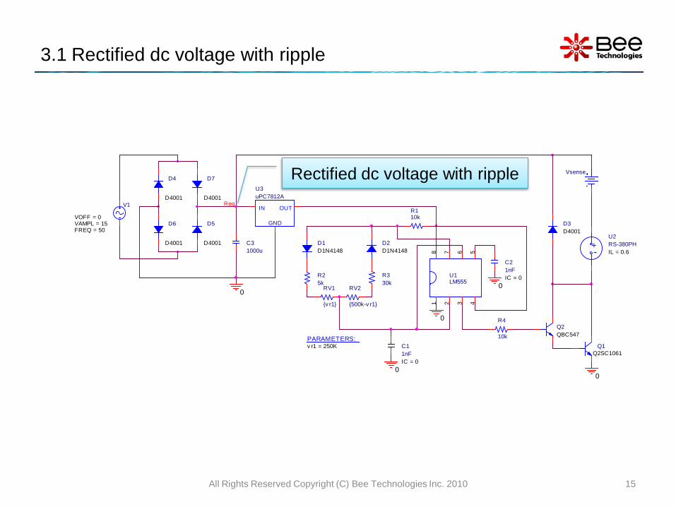
3.1 Rectified dc voltage with ripple
All Rights Reserved Copyright (C) Bee Technologies Inc. 2010 15
Rectified dc voltage with ripple
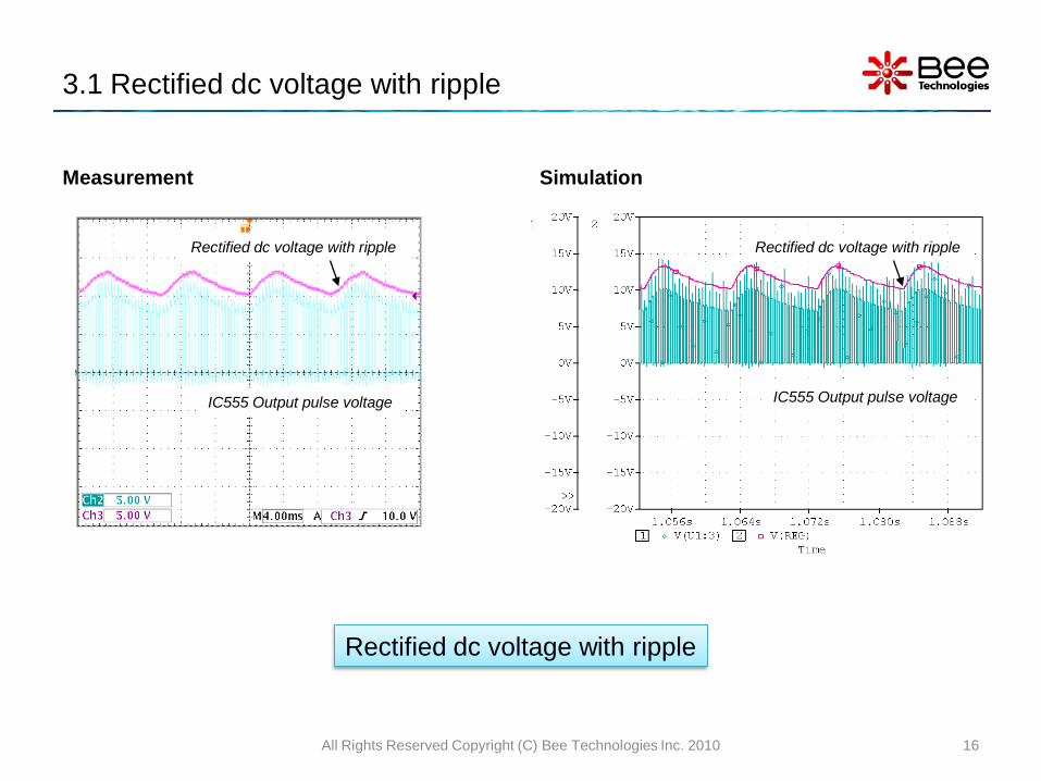
3.1 Rectified dc voltage with ripple
Measurement Simulation
All Rights Reserved Copyright (C) Bee Technologies Inc. 2010 16
IC555 Output pulse voltage
Rectified dc voltage with ripple
IC555 Output pulse voltage
Rectified dc voltage with ripple
Rectified dc voltage with ripple

C11nFIC = 0
0
D3D4001
D1D1N4148
R330k
R25k
D2D1N4148
RV1
v r1
RV2
500k-v r1
PARAMETERS:v r1 = 250K
OUT
GND
IN
U3uPC7812A
-+
U2RS-380PHIL = 0.6
R4
10k
Vsense
0
0
Q1Q2SC1061
Q2QBC547
R110k
C31000u
V1
FREQ = 50VAMPL = 15VOFF = 0
D5
D4001
D6
D4001
D7
D4001
D4
D4001
C21nFIC = 0
0
Reg
U1LM555
1 2 3 45678
0
3.2 IC 555 Output Pulse Voltage
All Rights Reserved Copyright (C) Bee Technologies Inc. 2010 17
IC 555 Output Pulse Voltage

3.2 IC 555 Output Pulse Voltage
Measurement Simulation
All Rights Reserved Copyright (C) Bee Technologies Inc. 2010 18
IC555 Output pulse voltageIC555 Output pulse voltage
IC 555 Output Pulse Voltage

C11nFIC = 0
0
D3D4001
D1D1N4148
R330k
R25k
D2D1N4148
RV1
v r1
RV2
500k-v r1
PARAMETERS:v r1 = 250K
OUT
GND
IN
U3uPC7812A
-+
U2RS-380PHIL = 0.6
R4
10k
Vsense
0
0
Q1Q2SC1061
Q2QBC547
R110k
C31000u
V1
FREQ = 50VAMPL = 15VOFF = 0
D5
D4001
D6
D4001
D7
D4001
D4
D4001
C21nFIC = 0
0
V-
V+
Reg
U1LM555
1 2 3 45678
0
3.3 Transistor Q2: VCE
All Rights Reserved Copyright (C) Bee Technologies Inc. 2010 19
Transistor Q2: VCE

3.3 Transistor Q2: VCE
Measurement Simulation
All Rights Reserved Copyright (C) Bee Technologies Inc. 2010 20
Transistor Q2: VCETransistor Q2: VCE
Transistor Q2: VCE

C11nFIC = 0
0
D3D4001
D1D1N4148
R330k
R25k
D2D1N4148
RV1
v r1
RV2
500k-v r1
PARAMETERS:v r1 = 250K
OUT
GND
IN
U3uPC7812A
-+
U2RS-380PHIL = 0.6
R4
10k
Vsense
0
0
Q1Q2SC1061
Q2QBC547
R110k
C31000u
V1
FREQ = 50VAMPL = 15VOFF = 0
D5
D4001
D6
D4001
D7
D4001
D4
D4001
C21nFIC = 0
0
V-
V+
Reg
U1LM555
1 2 3 45678
0
3.4 Transistor Q1: VCE, IC
All Rights Reserved Copyright (C) Bee Technologies Inc. 2010 21
Transistor Q1: VCE, IC

3.4 Transistor Q1: VCE, IC
Measurement Simulation
All Rights Reserved Copyright (C) Bee Technologies Inc. 2010 22
Transistor Q1: VCE
Transistor Q1: IC
Transistor Q1: VCE
Transistor Q1: IC
Transistor Q1: VCE, IC

C11nFIC = 0
0
D3D4001
D1D1N4148
R330k
R25k
D2D1N4148
RV1
v r1
RV2
500k-v r1
PARAMETERS:v r1 = 250K
OUT
GND
IN
U3uPC7812A
-+
U2RS-380PHIL = 0.6
R4
10k
Vsense
0
0
Q1Q2SC1061
Q2QBC547
R110k
C31000u
V1
FREQ = 50VAMPL = 15VOFF = 0
D5
D4001
D6
D4001
D7
D4001
D4
D4001
C21nFIC = 0
0
Reg
U1LM555
1 2 3 45678
0V-
V+
3.5 Motor Voltage and Current
All Rights Reserved Copyright (C) Bee Technologies Inc. 2010 23
Motor Voltage and Current

3.5 Motor Voltage and Current
Measurement Simulation
All Rights Reserved Copyright (C) Bee Technologies Inc. 2010 24
VMotor
IMotor
VMotor
IMotor
Motor Voltage and Current

C11nFIC = 0
0
D3D4001
D1D1N4148
R330k
R25k
D2D1N4148
RV1
v r1
RV2
500k-v r1
PARAMETERS:v r1 = 250K
OUT
GND
IN
U3uPC7812A
-+
U2RS-380PHIL = 1.5
R4
10k
Vsense
0
0
Q1Q2SC1061
Q2QBC547
R110k
C31000u
V1
FREQ = 50VAMPL = 13.5VOFF = 0
D5
D4001
D6
D4001
D7
D4001
D4
D4001
C21nFIC = 0
0
Reg
U1LM555
1 2 3 45678
0
4. LM555 DC Motor Speed Control Circuit (Fan Load)
Analysis directives: .TRAN 0 1.5s 0 4u SKIPBP .OPTIONS ABSTOL= 1.0u.OPTIONS GMIN= 1.0E-8.OPTIONS ITL4= 15.OPTIONS RELTOL= 0.01.OPTIONS VNTOL= 1.0m
All Rights Reserved Copyright (C) Bee Technologies Inc. 2010 25
• The circuit is simulated and compared with the measured waveforms from oscilloscope (Tektronix: TDS3054B) to verify the simulation using the RS-380PH model under the different load condition .

C11nFIC = 0
0
D3D4001
D1D1N4148
R330k
R25k
D2D1N4148
RV1
v r1
RV2
500k-v r1
PARAMETERS:v r1 = 250K
OUT
GND
IN
U3uPC7812A
-+
U2RS-380PHIL = 1.5
R4
10k
Vsense
0
0
Q1Q2SC1061
Q2QBC547
R110k
C31000u
V1
FREQ = 50VAMPL = 13.5VOFF = 0
D5
D4001
D6
D4001
D7
D4001
D4
D4001
C21nFIC = 0
0
Reg
U1LM555
1 2 3 45678
0
4.1 Rectified dc voltage with ripple
All Rights Reserved Copyright (C) Bee Technologies Inc. 2010 26
Rectified dc voltage with ripple

4.1 Rectified dc voltage with ripple
Measurement Simulation
All Rights Reserved Copyright (C) Bee Technologies Inc. 2010 27
IC555 Output pulse voltage
Rectified dc voltage with ripple
IC555 Output pulse voltage
Rectified dc voltage with ripple
Rectified dc voltage with ripple

C11nFIC = 0
0
D3D4001
D1D1N4148
R330k
R25k
D2D1N4148
RV1
v r1
RV2
500k-v r1
PARAMETERS:v r1 = 250K
OUT
GND
IN
U3uPC7812A
-+
U2RS-380PHIL = 1.5
R4
10k
Vsense
0
0
Q1Q2SC1061
Q2QBC547
R110k
C31000u
V1
FREQ = 50VAMPL = 13.5VOFF = 0
D5
D4001
D6
D4001
D7
D4001
D4
D4001
C21nFIC = 0
0
Reg
U1LM555
1 2 3 45678
0
4.2 IC 555 Output Pulse Voltage
All Rights Reserved Copyright (C) Bee Technologies Inc. 2010 28
IC 555 Output Pulse Voltage

4.2 IC 555 Output Pulse Voltage
Measurement Simulation
All Rights Reserved Copyright (C) Bee Technologies Inc. 2010 29
IC555 Output pulse voltageIC555 Output pulse voltage
IC 555 Output Pulse Voltage

C11nFIC = 0
0
D3D4001
D1D1N4148
R330k
R25k
D2D1N4148
RV1
v r1
RV2
500k-v r1
PARAMETERS:v r1 = 250K
OUT
GND
IN
U3uPC7812A
-+
U2RS-380PHIL = 1.5
R4
10k
Vsense
0
0
Q1Q2SC1061
Q2QBC547
R110k
C31000u
V-
V+
V1
FREQ = 50VAMPL = 13.5VOFF = 0
D5
D4001
D6
D4001
D7
D4001
D4
D4001
C21nFIC = 0
0
Reg
U1LM555
1 2 3 45678
0
4.3 Transistor Q2: VCE
All Rights Reserved Copyright (C) Bee Technologies Inc. 2010 30
Transistor Q2: VCE

4.3 Transistor Q2: VCE
Measurement Simulation
All Rights Reserved Copyright (C) Bee Technologies Inc. 2010 31
Transistor Q2: VCETransistor Q2: VCE
Transistor Q2: VCE

C11nFIC = 0
0
D3D4001
D1D1N4148
R330k
R25k
D2D1N4148
RV1
v r1
RV2
500k-v r1
PARAMETERS:v r1 = 250K
OUT
GND
IN
U3uPC7812A
-+
U2RS-380PHIL = 1.5
R4
10k
Vsense
0
0
Q1Q2SC1061
Q2QBC547
R110k
C31000u
V-
V+
V1
FREQ = 50VAMPL = 13.5VOFF = 0
D5
D4001
D6
D4001
D7
D4001
D4
D4001
C21nFIC = 0
0
Reg
U1LM555
1 2 3 45678
0
4.4 Transistor Q1: VCE, IC
All Rights Reserved Copyright (C) Bee Technologies Inc. 2010 32
Transistor Q1: VCE, IC

4.4 Transistor Q1: VCE, IC
Measurement Simulation
All Rights Reserved Copyright (C) Bee Technologies Inc. 2010 33
Transistor Q1: VCE
Transistor Q1: IC
Transistor Q1: VCE
Transistor Q1: IC
Transistor Q1: VCE, IC

C11nFIC = 0
0
D3D4001
D1D1N4148
R330k
R25k
D2D1N4148
RV1
v r1
RV2
500k-v r1
PARAMETERS:v r1 = 250K
OUT
GND
IN
U3uPC7812A
-+
U2RS-380PHIL = 1.5
R4
10k
Vsense
0
0
Q1Q2SC1061
Q2QBC547
R110k
C31000u
V-
V+
V1
FREQ = 50VAMPL = 13.5VOFF = 0
D5
D4001
D6
D4001
D7
D4001
D4
D4001
C21nFIC = 0
0
Reg
U1LM555
1 2 3 45678
0
4.5 Motor Voltage and Current
All Rights Reserved Copyright (C) Bee Technologies Inc. 2010 34
Motor Voltage and Current

4.5 Motor Voltage and Current
Measurement Simulation
All Rights Reserved Copyright (C) Bee Technologies Inc. 2010 35
VMotor
IMotor
VMotor
IMotor
Motor Voltage and Current

Simulations index
Simulations Folder name
1. Transient Response at No Load (Model)............................................
2. Speed at No Load (Model)..................................................................
3. The Motor Steady-State Current Condition Setting (1/2).....................
4. The Motor Steady-State Current Condition Setting (2/2).....................
5. Transient Response at Load 3.8A.......................................................
6. LM555 DC Motor Speed Control Circuit (No Load).............................
7. LM555 DC Motor Speed Control Circuit (Fan Load)...........................
¥Simulations¥Transient¥Trans_NoLoa
d
¥Simulations¥Transient¥Speed_NoLoa
d
¥Simulations¥Transient¥Steady State
¥Simulations¥Transient¥Trans_1A1
¥Simulations¥Transient¥Trans_3A8
¥Simulations¥Trans_NoLoad
¥Simulations¥Trans_FanLoad
All Rights Reserved Copyright (C) Bee Technologies Inc. 2010 36

Simulation Settings
Analysis directives: .TRAN 0 1.5s 0 4u SKIPBP .OPTIONS ABSTOL= 1.0u.OPTIONS GMIN= 1.0E-8.OPTIONS ITL4= 15.OPTIONS RELTOL= 0.01.OPTIONS VNTOL= 1.0m
All Rights Reserved Copyright (C) Bee Technologies Inc. 2010 37