design method for connections in engineered wood structures · pdf fileunb2 design method for...
TRANSCRIPT

Project No. UNB2 Value to Wood Project Research Report 2006
Design Method for Connections in Engineered Wood Structures
by
Ian Smith, Andi Asiz, and Monica Snow
Faculty of Forestry and Environmental Management University of New Brunswick, Fredericton
This report was produced as part of the Value to Wood Program, funded by Natural Resources Canada
March 2006

UNB2 Design Method for Connections in Engineered Wood Structures Page ii of 80
Executive Summary
Engineered Wood Products (EWP) now represents 5% of the overall structural wood product demand in North America, with production exceeding the equivalent of over 8 million cubic meters of sawn lumber per annum. Despite these statistics, design and test methods explicitly appropriate to EWP connections have not been developed. Currently the dominant design method for connections in EWP is to assume equivalency to similar connections in sawn softwood lumber members. This assumes direct correlation between behaviour of connections in EWP and lumber. Because the approach tends to be conservative it leads to wasted materials and thereby non-competitive EWP solutions, and lost market penetration especially into non-residential applications. As shown in this project not all EWP connections fail via mechanisms applicable to connections in solid wood. The equivalency concept is therefore flawed and a more rational engineering approach is required. The long-term goal of this project is to ensure that timber structures maintain a competitive position in relation to structures built with other common structural materials. The specific objectives include developing engineering design methods and reliability based design concepts for EWP connections, and implementation of project results in Canadian and international timber design codes. Project activities involved the understanding of the mechanical properties of EWP materials, the behaviour of connection systems, the appropriate application of common fasteners used with EWP, and the establishment of design methods and values using mechanics-based approaches for EWP connections and systems. Attention was also directed at investigating novel fasteners that exploit characteristics of EWP. Because of the need for consistence between design of connections in EWP and other wood-based products (especially sawn softwood lumber) attention was also directed at connections in sawn lumber. A global finding from this project is that in structural design distinction should be made between EWP that are high resistant to splitting at connections and those that are not. Laminated Strand Lumber (LSL), for example, has different failure patterns from most EWP and sawn lumber. When fasteners load members of sawn lumber or most types of EWP in an off member axis direction, strength is low. This is problematic because such situations are very common in practice. However LSL connections tend to be strong and fracture resistant for off axis loading. This shows that much potential of EWP in construction applications is not being exploited, and that the assumption of ‘equivalency to connections in sawn lumber’ is not generally valid. Based on test results from the project, it is possible with some EWP to eliminate the possibility of brittle failures at connections entirely, even when relatively large diameter fasteners like bolts are used. Lack of this feature has always plagued structures built from solid wood products. It is possible to create new EWP that exploit this and thereby open the door to new markets. This said, there is no point in having high performance products if there are not associated tools permitting engineers to exploit their capabilities. Design codes like CSA Standard 086-01 need to be radically overhauled to permit exploitation of the full potential of EWP. Draft proposals for code changes have been developed by the project team to the stage where there is an overall agreement on the need for a new generation of wood connection design practices in Canada. An initial framework for this is being refined under the auspices of the CSA086 Technical Committee for “Engineering Design in Wood”. It is intended that an initial ‘code change

UNB2 Design Method for Connections in Engineered Wood Structures Page iii of 80
proposal’ will be submitted to the committee during 2006 with the expectation that changes will be fully completed within the code revision cycle that will end in 2008. In parallel the project team is developing documentation supporting revision of international design practices. Using steel tube fasteners in tight fitting holes, instead of traditional solid steel bolts, is a highly effective means of avoiding brittle failures in connections, without or reduced need to reinforce members. Tubes create a softer contact with members than occurs with bolts and this reduces proneness to splitting failures. This applies to even the splitting prone EWP and sawn lumber. The project developed combinations of tube fasteners with steel splice plates slotted into the ends of wood members to create highly efficient connections. With the correct choices of tube dimensions and steel type such arrangements have strengths that approach the theoretical maximum. Such connections are cost effective and can be made as stronger as the members they join together. For sawn lumber and splitting prone EWP the research has shown that use of steel tube fasteners with outside diameters up to 6.4 mm (¼ inch) is most appropriate. Larger diameter tubes can be used with splitting resistant EWP. Novel numerical models have been developed to predict, and thereby know how to avoid, brittle failures in EWP connections. The new, so called advanced phenomenological, models overcome deficiencies of other methods and employ lattice network modelling schemes. Lattice elements of models replicate physical functions of morphological structures in solid wood or EWP and are statistically characterised. They properly simulate variability in response between nominally identical replications of any connection. No other models can do this. Although emphasis has been placed on applying lattice network modeling to bolted connections with sawn lumber or EWP members, the approaches are general and can be applied to any type of connection or to other situations. This is laying the foundation for a generalised analysis tool for description of failures in other structural wood components and systems. Recommended future work is:
• Tests on typical full scale structural systems (e.g. trusses, frames) to investigate how connection characteristics influence overall system behaviour, under different loading scenarios.
• Numerical case studies to investigate how connection characteristics influence overall system behaviour, under different loading scenarios.
• Development of design code provisions for wood structures that are fully consistent between sections in respect to expected functions for connections and how design capacities are assigned. Such provisions should be explicitly oriented toward system design instead of component design.
• Investigation of combinations of EWP and fasteners that fully exploit characteristics of various types of EWP, including creation of new high performance products.
Impacts/benefits to the wood industry resulting from findings of this project are: • Creation of rational methods via which structural designers can exploit superior
capabilities of modern EWP. • Justification for applying EWP in construction situations beyond their use as simple
substitutes for traditional solid wood products. • Creation of technical data supporting non-residential construction applications of EWP. • Creation of novel steel tube fasteners for use with EWP.
UNB2 Design Method for Connections in Engineered Wood Structures Page iv of 80
Acknowledgements
The University of New Brunswick acknowledges the financial support of this project by Natural Resources Canada. Thanks are due to the project champion Ken Koo of Jager Building Systems and industry liaisons Eric Jones of the Canadian Wood Council and Darian Wentland of Jager Building Systems. Their support and technical advice is much appreciated. The project team also thanks the following companies for in-kind material contributions:
• Jager Building Systems, Ontario. • Trus Joist, USA.
Research Staffs
• Dr. Ian Smith, Project Leader. • Dr. Andi Asiz, Research Associate. • Monica Snow, Graduate Student (Research Assistant). • Bona Murty, Graduate Student (Research Assistant). • Dean McCarthy, Chief Technician. • Shouyong Lai, Technician. • Scott Fairbank, Technician.

UNB2 Design Method for Connections in Engineered Wood Structures Page v of 80
Technical Papers/Documents Published
Asiz, A., Smith, I. (2005). A New Generation of Timber Design Practices and Code Provisions Linking System and Connection Design, International Council for Research and Innovation in Building and Construction – Working 18 Timber Structures (CIB-W18), Meeting 38, Paper No. 38-102-1, August 29 – 31, Karlsruhe, Germany. Murty, B. (2006) Wood and Engineered Wood Connections using Slotted Steel Plate(s) and Tight-Fitting Small Steel Tube Fasteners, Master Thesis, Faculty of Forestry and Environmental Management, University of New Brunswick, Fredericton, Canada. Murty, B., Asiz, A., Smith, I. (2006). Wood and Engineered Wood Product Connections Using Small Steel Tube Fasteners: An Experimental Study, Institute of Wood Science Journal, under review. Murty, B., Smith, I., Asiz, A. (2006). Wood and Engineered Wood Product Connections Using Small Steel Tube Fasteners: Applicability of European Yield Model, ASCE Journal of Materials in Civil Engineering, under review. Murty, B., Smith, I., Asiz, A. (2005). Design of Timber Connections with Slotted-in Steel Plates and Small Diameter Steel Tube Fasteners, International Council for Research and Innovation in Building and Construction – Working 18 Timber Structures (CIB-W18), Meeting 38, Paper No. 38-7-9, August 29 – 31, Karlsruhe, Germany. Snow, M. (2006) Fracture Development in Engineered Wood Product Bolted Connections, Doctoral Dissertation, Faculty of Forestry and Environmental Management, University of New Brunswick, Fredericton, Canada. Snow, M., Asiz, A., Chen, Z., Chui, Y.H. (2006). North American Practices for Connections in Wood Construction, Progress in Structural Engineering and Materials, accepted for publication. Snow, M., Asiz, A., Smith, I. (2005). Numerical Modeling of Multiple-Bolt Engineered Wood Products, 33rd Annual Conference of the Canadian Society for Civil Engineers, June 2-4, Toronto, Canada. Snow, M., Smith, I., Asiz, A. (2004). Dowel Joints in Engineered Wood Products: Assessment of Simple Fracture Mechanics Models, International Council for Research and Innovation in Building and Construction – Working 18 Timber Structures (CIB-W18), Meeting 37, Paper No. 37-7-15, August 31 – Sept 3, Edinburgh, Scotland, UK. Snow, M., Asiz, A., Smith, I. (2004). Failure Behaviour of Single Dowel Connections in Engineered Wood Products, 5th Structural Specialty Conference of the Canadian Society for Civil Engineers, June 2-5, Saskatoon, Saskatchewan, Canada.

UNB2 Design Method for Connections in Engineered Wood Structures Page vi of 80
List of Tables
Table 4.1: Specimen Strength ....................................................................................................... 18 Table 4.2: Ultimate loads of LSL bolt connections ...................................................................... 22 Table 4.3: Ultimate loads of LVL bolt connections ..................................................................... 23 Table 4.4: Ultimate loads of solid wood (pine) bolt connections ................................................. 23 Table 4.5: Ultimate loads of solid wood (spruce) bolt connections ............................................. 24 Table 4.6: Embedment strength for LSL ...................................................................................... 25 Table 4.7: Embedment strength for LVL...................................................................................... 25 Table 4.8: Embedment strength for Pine ...................................................................................... 25 Table 4.9: Embedment strength for Spruce .................................................................................. 25 Table 4.10: Comparison of experimental and modeling results specimen strength .................... 36 Table 5.1: Average test values for strengths of LSL joints........................................................... 42 Table 5.2: Average test values for strengths of Spruce joints...................................................... 43 Table 5.3: LSL tube connections .................................................................................................. 46 Table 5.4: LVL tube connections.................................................................................................. 46 Table 5.5: Pine tube connections .................................................................................................. 46 Table 5.6: EYM predicted and test average connection strengths: one fastener (kN).................. 48 Table 5.7: Tentative modification factors for design of tension joints / connections with dowel
type fasteners, based on equation (5)1................................................................................... 49 Table 7.1: Comparison of first failure loads and yield strength for wood and single bolt tests,
loaded perpendicular to strong wood / SCL member axis. ................................................... 56 Table 8.1: Dimensions of structural members .............................................................................. 59 Table 8.2: Material properties....................................................................................................... 59 Table 8.3: Applied loads** ........................................................................................................... 62 Table 8.4: Load cases.................................................................................................................... 62 Table 8.5: Forces and displacements in connector shear planes, with linear dowel response...... 63 Table 8.6: Forces and displacements in connector shear planes at around failure load, with non-
linear dowel response model................................................................................................. 64

UNB2 Design Method for Connections in Engineered Wood Structures Page vii of 80
List of Figures Figure 4.1: Test Set-up with LVL Centre Member....................................................................... 18 Figure 4.2: Joint failures for single bolt, for 4 materials tested .................................................... 19 Figure 4.3: Typical Load-Crosshead Displacement Curves ......................................................... 19 Figure 4.4: Test set up for large EWP connection ........................................................................ 20 Figure 4.5: Connection configuration parameters ........................................................................ 21 Figure 4.6: Failure mechanisms of large EWP connections ......................................................... 22 Figure 4.7: Embedment test set up................................................................................................ 24 Figure 4.8: Failure modes for embedment tests............................................................................ 25 Figure 4.9: Connection failures for 2 rows-1 bolt configuration, LSL and Pine .......................... 27 Figure 4.10: Connection failures for 2 rows-2 bolt configuration, LSL and Pine ........................ 27 Figure 4.11: Predicted deformed shapes and potential failure sites at ultimate load in 2 bolt (2
rows-1 bolt) joints (left half-specimen shown in each diagram) ......................................... 28 Figure 4.12: Predicted deformed shapes and potential failure sites at ultimate load in 4 bolt (2
rows-2 bolts) joints (left half-specimen shown in each diagram)........................................ 28 Figure 4.13: Mode I and Mode II compact fracture tsts .............................................................. 29 Figure 4.14: Mode I facture Figure 4.15: Mode II facture................................... 30 Figure 4.16: Mode I Load Displacement Curve .......................................................................... 30 Figure 4.17: Mode II Load Displacement Curves ....................................................................... 31 Figure 4.18: Stress intensity factors for LSL............................................................................... 32 Figure 4.19: Stress intensity factors for Pine ............................................................................... 32 Figure 4.20: Predicted crack propagation load vs. crack length for LSL and Pine ..................... 33 Figure 4.21: LSL strand orientation............................................................................................. 34 Figure 4.22: Lattice network orientation of elements for single LSL truss panel ....................... 34 Figure 4.23: Lattice network arrangement of LSL elements ....................................................... 35 Figure 4.24: Experimental and model results of failed Pine centre member loaded perpendicular
to strong axis (grain) ............................................................................................................. 36 Figure 4.25: Experimental and model results of failed LSL centre member load perpendicular to
strong axis ............................................................................................................................. 37 Figure 4.26: Experimental and model results of failed Pine centre member loaded parallel to
strong axis (grain) ................................................................................................................. 38 Figure 4.27: Experimental and model results of failed LSL centre member loaded parallel to
strong axis ............................................................................................................................. 38 Figure 5.1: Slotted-in steel plate with steel tube fasteners in EWP connections.......................... 40 Figure 5.2: Specimen arrangement ............................................................................................... 41 Figure 5.3: Test setup.................................................................................................................... 42 Figure 5.4 : Failed LSL joint......................................................................................................... 43 Figure 5.5: Load-slip curves for 6 replicates of LSL joints with four 6.4 mm fasteners.............. 43 Figure 5.6 : Failed Spruce joint..................................................................................................... 44 Figure 5.7: Load-slip curves for 6 replicates of Spruce joints with four 6.4 mm fasteners.......... 44 Figure 5.8: Connection failures for LSL, LVL, and pine.............................................................. 45 Figure 5.9: Tube connections configuration ................................................................................. 45 Figure 5.10: EYM mechanisms for a wood–steel plat–wood connection .................................... 47

UNB2 Design Method for Connections in Engineered Wood Structures Page viii of 80
Figure 5.11: Finite element mesh and deformed shape (one 6.4 mm fastener) ............................ 50 Figure 5.12: Deformed shape and principal stresses of the steel tube after yielding (one 6.4 mm
fastener)................................................................................................................................. 50 Figure 5.13: Load-slip curves from tests and finite element model (one 6.4 mm fastener) ......... 50 Figure 7.1: Schematic drawing of test set-up based on ASTM D5652 protocol, loading
perpendicular to strong axis. ................................................................................................. 54 Figure 7.2: Schematic drawing of failure mechanisms for test set-up based on ASTM D5652
protocol for loading perpendicular to strong axis ................................................................. 55 Figure 7.3: Schematic drawing of Tee Beam test arrangement, loading perpendicular to strong
axis ........................................................................................................................................ 57 Figure 7.4: Schematic drawing of Propped Beam test arrangement, loading perpendicular to
strong axis ............................................................................................................................. 57 Figure 8.1: Portal frame structure studied..................................................................................... 59 Figure 8.2: Connection model and frames numbering system ..................................................... 60

UNB2 Design Method for Connections in Engineered Wood Structures Page ix of 80
Table of Contents
Executive Summary ..................................................................................................................... ii Acknowledgements ..................................................................................................................... iv Research Staffs ........................................................................................................................... iv Technical Papers/Documents Published.................................................................................. v List of Tables................................................................................................................................ vi List of Figures ............................................................................................................................. vii Table of Contents ........................................................................................................................ ix 1 Objectives ............................................................................................................................ 11 2 Introduction.......................................................................................................................... 11 3 Survey of Wood Connections in North America ............................................................ 13
3.1 Background ................................................................................................................. 13 3.2 Survey Results............................................................................................................ 13
3.2.1 Engineers Results.................................................................................................. 13 3.2.2 Architect Results................................................................................................... 15 3.2.3 Follow-up Actions ................................................................................................ 16
3.3 Concluding Remarks ................................................................................................. 16 4 Bolted Connections in Engineered Wood Products...................................................... 17
4.1 Test of EWP Bolted Joints ........................................................................................ 17 4.2 Test of Large EWP Connections ............................................................................. 20 4.3 Embedment Test ........................................................................................................ 24 4.4 Numerical Model Development ................................................................................ 26
4.4.1 Continuum finite element analysis........................................................................ 26 4.4.2 Fracture Mechanics Approach .............................................................................. 29 4.4.3 Discrete element model using lattice network ...................................................... 33
4.5 Concluding Remarks ................................................................................................. 39 5 Steel Tube Fasteners in EWP Connections .................................................................. 40
5.1 Introduction.................................................................................................................. 40 5.2 Testing Programme ................................................................................................... 41
5.2.1 Joint tests............................................................................................................... 41 5.2.2 Large connection test ............................................................................................ 44
5.3 Mechanics Based Model (European Yield Model) ................................................ 47 5.4 Proposed Code Equation .......................................................................................... 48 5.5 Finite Element Analysis ............................................................................................. 49 5.6 Concluding Remarks ................................................................................................. 50
6 Code Change Proposal to O86-01: Design of Structural Wood Connections.......... 52 7 Proposed General Testing Protocol for Structural Wood Connections ..................... 54
7.1.1 Proposed Alternative test methods........................................................................ 56 8 Case Studies/Example of Applications ........................................................................... 58
8.1 Introduction.................................................................................................................. 58 8.2 Portal frame study ...................................................................................................... 58
8.2.1 Description of structure......................................................................................... 58

UNB2 Design Method for Connections in Engineered Wood Structures Page x of 80
8.2.2 Modeling of dowels .............................................................................................. 60 8.2.3 Loads..................................................................................................................... 61 8.2.4 Linear model evaluation ....................................................................................... 61 8.2.5 Non-linear model evaluation................................................................................. 63
8.3 Concluding Remarks ................................................................................................. 64 9 Conclusion and Recommendation .................................................................................. 65 10 References ...................................................................................................................... 67 Appendix I.................................................................................................................................... 69

UNB2 Design Method for Connections in Engineered Wood Structures Page 11 of 80
1 Objectives The long-term goal of this project is to ensure that timber structures maintain a competitive position in relation to structures built with other common structural materials. The specific objectives are:
• To develop design methods for structural connections in engineered wood products, i.e. methods that reflect the characteristics of those products.
• To develop methods for reliability based design of structural wood connections. • To pursue implementation of project results in Canadian and international timber design
codes. 2 Introduction Engineered Wood Products (EWP) now represents 5% of the overall structural wood product demand in North America, with a projected production of laminated veneer lumber, I-Joists and glulam alone exceeding the equivalent of over 8 million cubic meters per annum (UNECE/FAO 2003). Despite these statistics no engineering design and test methods explicitly appropriate for EWP connections have been developed in Canada or elsewhere. This reflects relative newness of many products, their complexity and the proprietary nature of EWP and some types of fasteners. Current design methods for connections in EWP are based on establishing equivalency criteria in which the design procedure assumes direct correlation between behaviour of EWP connections and similar connections in sawn lumber. This approach tends to be conservative leading to wasted materials, and thereby non-competitive solutions and lost market access opportunities. This project is aimed at developing generalized methods for assigning design resistances to connections in EWP, taking account the physical characteristics of such products and various possible brittle and ductile failure modes. Project activities involved the understanding of: mechanical properties of EWP materials; the behaviour of connection systems; appropriate application of common fasteners used with EWP; and the establishment of design methods and values using mechanics-based approaches for EWP connections and systems. Attention was also directed at investigating novel fasteners that exploit characteristics of EWP. Because of the goal for consistency between design of connections in EWP and other wood-based products (especially sawn softwood lumber) attention was also directed at connections in sawn lumber. Specific activities were:
• Review of current construction use and design practices via broad-based electronic surveys distributed to structural designers and architects in Canada and USA. Supplementary in depth telephone interviews with sub-samples of respondents, and consultations with experts, refined the findings from the broad-based surveys. The surveys and interviews / consultations guided the choice of other project activities.
• Testing of connections was undertaken for traditional steel dowel and innovative steel
tube fasteners, with EWP materials used being Laminated Veneer Lumber (LVL),

UNB2 Design Method for Connections in Engineered Wood Structures Page 12 of 80
Parallel Strand Lumber (PSL) and Laminated Strand Lumber (PSL), as well as sawn softwood lumber as a benchmark.
• Development of numerical and analytical modelling techniques for predicting
deformation characteristics, and ultimate loads and associated failure mechanisms of connections. This included investigation of the applicability of simple mechanics based models, such as the European Yield Model for dowel fastener joints, for assessing connection strength. Numerical tools developed include continuum finite element analysis methods, fracture mechanics analyses, and phenomenological discrete element representations that use lattice networks of elements. Complex numerical and phenomenological models are not expected to be practical for design but are invaluable as the basis for developing simple, robust and acceptably accurate mechanics based methods that design engineers can apply on an everyday basis. The objective is that simple methods be as far as possible consistent with how structural designers approach analysis for other primary construction materials (e.g. structural steel). Also to make transparent what type of mechanism is to be expected. Currently designers cannot do this.
• Establishing design principles and test protocols for connection in timber structures and
application of those principles and protocols within the framework of the Canadian regulatory regime (including proposed revision to the Canadian Standards Association (CSA) Standard O86-01 “Engineering Design in Wood”). Those principles are aimed at comparable solutions, e.g. number of fasteners required, irrespective of whether the starting point is mechanics based calculations or data from tests on real scale connections. Principles and test protocols are also being promoted for international adoption as market support and development for EWP.

UNB2 Design Method for Connections in Engineered Wood Structures Page 13 of 80
3 Survey of Wood Connections in North America 3.1 Background Between October 2003 and March 2004, a formal survey was conducted to investigate current North American practices for connections in wood construction, under the auspices of the Wood Science and Technology Centre (WSTC) at the University of New Brunswick as part of this project. The main objective of these efforts was to assess how and why US and Canadian structural engineers and Canadian architects select, design, and specify connections that join lumber and other structural wood-based products. It was anticipated that the survey results would give general guidance on research necessary under this project. The primary method of conducting the survey was through distribution of questionnaires, although records of discussion with respondents, experts, and manufacturers were also used in summarizing the survey findings. Engineers and architects were provided different survey instruments. The engineers’ survey had six parts: 1) general information, 2) types of materials used, 3) types of connections used, 4) details of each type of connection specified, 5) comments, concerns and suggestions about design practice and 6) research needs. The architect’s survey contained similar questions as engineers without the more detailed questions relating to design and specification of hardware. Architect questions were adjusted to reflect their decision-making role in the design process and questions relating to aesthetics and interaction with structural engineers were also included. Surveys were distributed to engineers and architects directly from the WSTC or through professional organizations including the Canadian Society for Civil Engineering (CSCE), American Society of Civil Engineers (ASCE), American Wood Council (AWC), Canadian Wood Council (CWC) and several provincial architectural associations in Canada. Professional organizations were either willing to provide access to their web homepages or email the survey directly to their members. 3.2 Survey Results 3.2.1 Engineers Results Survey results related to general design issue indicate that: • The most common connection design is for light frame construction with bearing, roof-to-
wall and wall-to-foundation identified as the most common requirements. • Engineers considered strength and ease of fabrication to be the primary factors in deciding
specification of wood and wood-based product connections. • A wide range of Engineered Wood Products (EWP) are specified in design, with the most
common products specified being wood I-joist, glulam, Parallel Strand Lumber (PSL) and Laminated Veneer Lumber (LVL).
• Application of rigid adhesives in conjunction with mechanical fasteners such as nails, screws and bolts is a common practice.

UNB2 Design Method for Connections in Engineered Wood Structures Page 14 of 80
• There is no distinction made by engineers between suitability of fasteners in design of connections that resist lateral forces created by wind loads or seismic events.
Survey results on types of connections specified in design indicate that:
• Nails, spikes, wood screws, lag screws, and bolts are the most common fasteners specified for all wood and wood-based materials connection systems.
• Staples are primarily used for connecting panel products such as Oriented Strand Board (OSB) and plywood to solid sawn lumber or Structural Composite Lumber (SCL) products.
• Timber rivets, drift pins and shear plates are specified for connecting steel plate to SCL or solid wood (sawn lumber and glulam). (Note: The standard length timber rivets is insufficient to make SCL connections and guidance for use of this fastener with SCL is not included in either the US or Canadian wood design codes).
• Split rings are specified for SCL to SCL or SCL to solid wood. Note: Use of split rings with SCL is inconsistent with manufacturer recommendations.
• Unconventional (proprietary) connections are very common fasteners for connecting EWPs.
• Nails, spikes, lag screws and bolts are commonly specified for single shear load conditions.
• Bolts are the most common fastener specified for double shear load conditions. Respondent concerns highlighted by the survey reflect difficulties in designing connections, especially designs with bolts, shear plates, split ring connectors and traditional joinery connections. Respondents attributed difficulties to the complexity of the design process and the scarcity or incomplete compilation of design information. Deficiencies in wood connection design guidance identified by engineers who responded to the survey include:
• Screw connections (Canada), • Staple connections, • Moment connections, • Traditional joinery (hardwood dowel and mortise and tenon), • EWP properties and criteria for selecting connections for EWP, • Non-factory gluing, • Modification factors for connections, and • Fire protection of heavy timber connections.
Research suggestions provided by structural engineer respondents include:
• Methods for identifying failure modes, • Wood screw joints, • EWP connections, • Correlation of design capacities for power driven versus hammer driven nails, and • Multiple bolt and multiple shear planes connections.
UNB2 Design Method for Connections in Engineered Wood Structures Page 15 of 80
3.2.2 Architect Results
Architects indicated that if they involve engineers in the design process, they may be engaged at the conceptual stage, during preliminary costing or during the detailed design stage. Essentially, architects only involve structural engineers in the design of large structures or complex buildings outside prescriptive construction regulations.
Respondents to the architect’s survey specify EWP in their design, specifically wood I-joists. With respect to what connections are specified in their designs, the general response was to use dowel-type connections such as nails and spikes, bolts, wood screws, lag screws, and bolts for the connection of wood and structural wood composite products. The majority of architect had no difficulties with selection of connections, but had some concerns over balancing structural integrity, economy and ease of installation in the design. As for aesthetic connection design, requirements identified by respondents include:
• Concealed, neat and ‘paintable’ connections, • Bolts and steel plates, • Half-lap board and batten, • Dowels/pins, mortise and tenon and • Bayonet-type connectors (minimize bulky plates).
As a general concept, architects and their clients prefer exposed connections in heavy-frame timber with lots of steel and bolts visible. Proprietary or unconventional connection design considerations identified by respondents include:
• Fasteners that were not too conspicuous or bulky, • Exposed bolts and steel plates, • Slip connections that allowed for seismic movement and shrinkage, • Custom stainless steel stirrups and hangers, • Galvanized plates, and • Custom triangular truss supports.
Architects who responded to the survey felt that the lack of adequate information on connection design could be remedied with a simple and standard approach for given applications, design and bracing information for large span roof trusses, and software tools to facilitate the connection design process. As for research, architects wanted research to focus on:
• Corrosion resistance, • Repair of traditional joinery, • Design of exterior exposed connections, and • Cost and delivery of connections.

UNB2 Design Method for Connections in Engineered Wood Structures Page 16 of 80
3.2.3 Follow-up Actions Following compilation of the survey responses, electronic mail and telephone interviews were conducted to clarify some ambiguities. From these follow-up discussions, it was clear that there needs to be a better understanding of multiple shear plane connection applications, large capacity bolted connections, concealed mechanical fasteners, and rigid (moment resistant) connection for post-to-beam attachment. 3.3 Concluding Remarks Based on this survey activity, conclusions can be drawn as follow.
• There is a diverse need and demand for guidance in designing connections in wood construction throughout North America.
• There is a general unawareness that acceptable, recommended, and appropriate standards
do exist, although there appears to be a lack of dissemination of the available information.
• North American design codes must be updated to reflect the increased acceptance and use
of EWP. This will necessitate expansion of existing research efforts.

UNB2 Design Method for Connections in Engineered Wood Structures Page 17 of 80
4 Bolted Connections in Engineered Wood Products There are two important issues associated with design of connection in wood structures:
• Ability to predict and therefore control whether particular design solutions will result in failure modes that are brittle or ductile, and
• Development of efficient and economic connection methods. These two issues were addressed in this project through graduate student theses of Monica Snow (Snow, 2006) and Bona Murty (Murty, 2006), respectively. This section summarizes work of Monica Snow including her testing programme on bolted connections in various EWP, and development of numerical models to predict failure modes and associated ultimate loads. The testing programme is important for numerical modeling verification and once the models have been fully developed and verified their prediction will become the template for assessing and developing simple mechanics based methods that can be easily used by engineers.
4.1 Test of EWP Bolted Joints Tests were conducted at the joint and connection levels. Joint refers to the attachment of one end of one member to ‘the remainder of a structural system’, via one or more link elements. A connection is a construction detail that interconnects a number of elements. Connections contain a number of joints. Tests were conducted in 2004 to examine the failure behaviour for single bolt joints in EWP under static load, perpendicular to strength axis (grain). Test results provide a comparison of experimental results with the code-accepted species equivalency criteria. For this study, a test set-up was developed to examine possible brittle and ductile failure mechanisms of single dowel joints in Laminated Veneer Lumber (LVL), Parallel Strand Lumber (PSL), and Laminated Strand Lumber (LSL), with Eastern White Pine [Pinus strobus L.] sawn lumber used as a control case. The test method was based on procedures outlined in ASTM D5652-95 R2000, “Standard Test Methods for Bolted Connections in Wood and Wood-Base Products” and ASTM D5456-05a, Annex A2 (2005) “Standard Specification for Evaluation of Structural Composite Lumber Products”, with supplementary data collection using digital image recording to capture initiation of the fracture process during loading. The image records were used to establish deformation and fracture patterns of the wood elements and identify the failure mechanisms of the single-bolt joint system. Traditionally, a set of 12.7 mm (½″) to 25.4 mm (1″) thick steel plates is used in steel-wood-steel connection systems. To allow image recording, the steel of the connection system was replaced with 33 mm (1¼″) thick GE Lexan® high strength transparent polycarbonate material. The test arrangement shown in Figure 4.1 sits within a universal test machine that applied and recorded the load vs. time.

UNB2 Design Method for Connections in Engineered Wood Structures Page 18 of 80
Figure 4.1: Test Set-up with LVL Centre Member A summary of test results for strength of joints in the four test materials is shown in Table 4.1. These include mean values (kN) of applied load corresponding to the appearance of the first surface cracks of length 10 mm, yield point, and ultimate strength.
Table 4.1: Specimen Strength Load (kN) - 1st Crack Yield Strength (kN) Ultimate Strength (kN) Pine LVL PSL LSL Pine LVL PSL LSL Pine LVL PSL LSL Mean 7.5 9.9 11.3 26.7 7.8 15.4 16.1 21.9 8.6 16.6 17.7 28.4 Standard Deviation 0.7 1.9 1.8 4.3 0.7 0.7 1.2 4.3 0.9 0.4 1.1 3.1
Coefficient of Variation 10% 20% 15% 16% 9% 5% 7% 20% 10% 2% 6% 11%
Figure 4.2 presents typical failure patterns of the single bolt joints, for the four materials tested.
Pine PSL

UNB2 Design Method for Connections in Engineered Wood Structures Page 19 of 80
LVL LSL
Figure 4.2: Joint failures for single bolt, for 4 materials tested
Figure 4.3 is a graphical representation of typical load-crosshead displacement curves. The initial concavity of each response is due to take-up of slack in the dowel hole. There was little practical difference in initial stiffness for various SCL materials and solid wood once the dowel bedded down, but clearly there were some differences in ultimate load and failure characteristics.
Figure 4.3: Typical Load-Crosshead Displacement Curves From the above results, it can be concluded that the species equivalency approach tends to be conservative for SCL products of LVL, PSL and LSL under the ASTM D5652-95 R2000 method of testing. However, there is need for caution in extrapolating the conclusion and applying it to joints and connections in general. Deductions about the apparent presence or absence of ductility in joints can be misleading. As indicated by fracture process observations for pine and LSL specimens in particular, the apparent ductility can represent development of an alternative

UNB2 Design Method for Connections in Engineered Wood Structures Page 20 of 80
(secondary) load carrying mechanism where the wood material has separated at the joint and the material below the bolt is acting as a simply supported beam. In actuality, the connection failure has already occurred. Specifically, using the ASTM D5652-95 R2000 method of testing the post-peak load carrying mechanism can be beam bending. It is concluded that this particular standardised method of testing is unrealistic and unreliable as a means of quantifying likely relative capacities of connections. Rather, the ASTM D5652-95 R2000 method provides a means of assessing suitability of alternative member materials. It is clear that fracture behaviour of the different EWP or solid wood has a profound influence on joint behaviour.
4.2 Test of Large EWP Connections Tests on large EWP connections loaded parallel to the strong axis (grain) were conducted using a high capacity tension machine. All specimens consist of two identical EWP/wood members connected with steel plates. Two LVDT’s were mounted at each member to measure relative displacement with total deformation recorded using the grip movement of the tension machine (Figure 4.4). Due to brittle nature of connection failure, the LVDTs were removed from the connection test set up when the load reached about 65% of the predicted ultimate load to avoid damaging them. ISO test standards for static load were the basis for the work and realistically simulate in-service conditions. The connections were loaded at about 65% of the ultimate load first and that level of load held for several seconds, then released (unloaded), before reloading until failure.
Figure 4.4: Test set up for large EWP connection
EWP materials used were LVL and LSL with solid woods (pine and spruce) used as reference cases. All EWP and wood members used were 1.5” by 5.5”. The number of bolts used were: (1) three in one-row, (2) six in two rows of three, and (3) one bolt as reference case. Connection configuration parameters are defined in Figure 4.5. In this test, variation in end distance (e), bolt spacing (c), and spacing between rows (r) of the connections was investigated. Bolt diameter was kept constant at ½”. There were 13 connection configurations (groups) for LSL, LVL, and pine,
LVDT2
specimen1
boltplate
24” 24” ~1/2”
clip
LVDT1
specimen2

UNB2 Design Method for Connections in Engineered Wood Structures Page 21 of 80
with 10 replicates each. Due to limited material for spruce, only six groups (10 replicated each) were tested. Moisture contents were about 7-8% for LSL and LVL, and about 13% for solid wood.
Notes: Nc = number of bolts per row (column); Nr = number of rows of bolts; e = end distance; r = row spacing; c = spacing in the row; d = diameter of bolt
Figure 4.5: Connection configuration parameters
The test results for bolted connections indicate failure modes consistent with those from previous tests on small joints. Majority of connections failed in brittle modes under load parallel to the member axis. Typical Laminated Strand Lumber (LSL) connections failed in the net-section in tension, while similar LVL and solid wood connections failed by shear-out of rows of bolts (Figure 4.6). Also, LSL connection capacity is much closer to member strength compared to LVL and solid wood connections. As expected solid woods (pine and spruce) shows larger variations (large CoV) in the ultimate strengths compared to LSL and LVL. Within the solid woods themselves, pine showed larger CoV than spruce in the ultimate strength.
(a) Pine
(b) Spruce
L
c e
rNr
Nc
d

UNB2 Design Method for Connections in Engineered Wood Structures Page 22 of 80
(c) LSL
(d) LVL
Figure 4.6: Failure mechanisms of large EWP connections
Detail test results for LSL, LVL, pine, and spruce connections are presented in Tables 4.2-4.4. The general observation for LSL is that the strength of six bolt connections are about six times the strength of a single bolt connections, i.e., the commonly observed ‘group effect’ for multiple bolts is not significant. For LVL and solid woods, the group factor for multiple fasteners is significant. Furthermore, for LSL and LVL, changing row spacing from 4d to 5d in the six bolt connections does not has significant effect on the ultimate strength, while for solid wood it does. For LVL and solid woods, end distance (e) has significant effect on the connection strength, but not for LSL. With only six ½” bolts the connections are as strong as the members for LSL. From this it is clear that EWP’s can overcome problems that traditionally plague wood connections, which opens the door to applications hitherto thought technically infeasible.
Table 4.2: Ultimate loads of LSL bolt connections Note: LSL tensile strength= 209 kN.
Specimen Group
No. Bolts d e c r
Ultimate Load (kN)
CoV (%)
MC (%)
SB-1-1-01 1 0.50 2.00 34.64 6.53 8.04 SB-1-3-01 3 0.50 2.00 2.00 98.02 11.18 7.42 SB-1-3-02 3 0.50 2.00 3.00 112.94 9.58 7.26 SB-1-3-03 3 0.50 3.00 2.00 108.88 5.40 7.69 SB-1-3-04 3 0.50 3.00 3.00 120.50 4.56 7.57 SB-2-3-01 6 0.50 2.00 2.00 2.50 208.10 10.25 7.23 SB-2-3-02 6 0.50 2.00 3.00 2.50 211.64 5.44 7.52 SB-2-3-03 6 0.50 3.00 2.00 2.50 204.77 7.33 8.15 SB-2-3-04 6 0.50 3.00 3.00 2.50 212.70 1.35 8.12 SB-2-3-05 6 0.50 2.00 2.00 2.00 195.88 9.02 7.78 SB-2-3-06 6 0.50 2.00 3.00 2.00 207.84 4.52 7.45 SB-2-3-07 6 0.50 3.00 2.00 2.00 204.16 7.63 7.08 SB-2-3-08 6 0.50 3.00 3.00 2.00 190.34 6.33 8.20

UNB2 Design Method for Connections in Engineered Wood Structures Page 23 of 80
Table 4.3: Ultimate loads of LVL bolt connections
Specimen Group
No. Bolts d e c r
Ultimate Load (kN)
COV (%) MC (%)
LB-1-1-01 1 0.50 3.50 21.71 7.06 7.66LB-1-1-02 1 0.50 5.00 22.03 13.42 7.73LB-1-3-01 3 0.50 3.50 2.00 38.68 4.02 7.39LB-1-3-02 3 0.50 3.50 3.00 48.83 10.24 7.15LB-1-3-03 3 0.50 5.00 2.00 51.64 12.69 6.99LB-1-3-04 3 0.50 5.00 3.00 60.65 4.98 7.18LB-2-3-01 6 0.50 3.50 2.00 2.50 75.58 5.27 7.79LB-2-3-02 6 0.50 3.50 3.00 2.50 102.32 11.65 7.74LB-2-3-03 6 0.50 5.00 2.00 2.50 94.46 10.18 7.65LB-2-3-04 6 0.50 5.00 3.00 2.50 113.86 8.60 7.38LB-2-3-05 6 0.50 3.50 2.00 2.00 91.02 9.63 7.27LB-2-3-06 6 0.50 3.50 3.00 2.00 96.34 15.61 7.75LB-2-3-07 6 0.50 5.00 2.00 2.00 92.04 13.41 7.99LB-2-3-08 6 0.50 5.00 3.00 2.00 111.88 8.17 7.57
Note: LVL tensile strength=200 kN
Table 4.4: Ultimate loads of solid wood (pine) bolt connections
Specimen Group
No. Bolts d e c r
Failure Load (kN)
COV (%)
MC (%)
PB-1-1-01 1 0.50 3.50 14.24 8.06 9.35 PB-1-1-02 1 0.50 5.00 15.73 13.65 9.54 PB-1-3-01 3 0.50 3.50 2.00 18.91 16.58 13.37 PB-1-3-02 3 0.50 3.50 3.00 23.17 27.26 12.50 PB-1-3-03 3 0.50 5.00 2.00 29.17 21.38 11.74 PB-1-3-04 3 0.50 5.00 3.00 33.86 4.84 12.37 PB-2-3-01 6 0.50 3.50 2.00 2.50 59.03 18.82 14.09 PB-2-3-02 6 0.50 3.50 3.00 2.50 55.48 18.93 14.64 PB-2-3-03 6 0.50 5.00 2.00 2.50 57.15 9.69 15.63 PB-2-3-04 6 0.50 5.00 3.00 2.50 59.80 5.40 13.42 PB-2-3-05 6 0.50 3.50 2.00 2.00 45.48 12.84 13.16 PB-2-3-06 6 0.50 3.50 3.00 2.00 55.32 18.45 12.72 PB-2-3-07 6 0.50 5.00 2.00 2.00 50.44 25.69 13.11 PB-2-3-08 6 0.50 5.00 3.00 2.00 52.45 22.19 12.74
Note: Pine tensile strength=79 kN

UNB2 Design Method for Connections in Engineered Wood Structures Page 24 of 80
Table 4.5: Ultimate loads of solid wood (spruce) bolt connections
Specimen Group
No. Bolts d e c r
Failure Load (kN)
COV (%)
MC (%)
SpB-1-1-01 1 0.50 3.50 16.24 9.86 13.43 SpB-1-1-02 1 0.50 5.00 13.59 15.94 13.59 SpB-1-3-01 3 0.50 3.50 2.00 35.84 3.78 13.54 SpB-1-3-04 3 0.50 5.00 3.00 42.72 7.18 13.04 SpB-2-3-01 6 0.50 3.50 2.00 2.50 72.60 15.74 13.45 SpB-2-3-04 6 0.50 5.00 3.00 2.50 78.50 13.43 13.58
Note: Spruce tensile strength=100 kN 4.3 Embedment Test Embedment strength is one of the important parameters used to estimate capacity of wood connections, based on the so-called European Yield Model (EYM). Embedment strength, which is determined by testing, is a function of wood species (density) and geometry. In this study, embedment tests were performed to determine dowel-bearing capacities for LSL, LVL, and solid woods. The embedment tests were performed based on ASTM D5764-97a using the half-hole method (Figure 4.7) with loading applied parallel, perpendicular, and at angles relative to the strong axis/grain direction. The half-hole method was used because preliminary tests showed unsatisfactory result for the alternative full-hole method due to excessive bending developed in the dowel before crushing occurred in the wood. LSL, LVL and solid wood were cut into the size of 1½ ” (38mm) x 3 3/8” (89mm) x 3 3/8”(89 mm). A dowel with the diameter of ½” was inserted to the half-hole of the member. Tests were conducted using an Instron machine that applied compression up to failure (ultimate load) at the rate of loading 0.04 in./min (1.0 mm/min). Six replicates were used for each set of specimen variables.
Figure 4.7: Embedment test set up
Main failure modes observed were crushing of wood for LSL, and splitting for LVL and solid woods (Figure 4.8). Moreover, in LVL and solid woods splitting first occurred before the ultimate load was reached. For LSL there no splitting was observed. The embedment strengths
Loaded length
Loading block
Dowel
Specimen
Stationary crosshead
Movable crosshead
LVDT
Front View
P Load
Side View
P Load

UNB2 Design Method for Connections in Engineered Wood Structures Page 25 of 80
were calculated based on the 5 % dowel-diameter offset relative to the maximum tangential stiffness. The test results are summarized in Tables 4.6-4.9.
(a) LSL (b) LVL (c) pine
Figure 4.8: Failure modes for embedment tests (parallel to the strong axis/grain)
Table 4.6: Embedment strength for LSL Angle
(degree) Embedment
Strength (Mpa) CoV (%) Moisture
Content (%) 0 50.88 9.72 7.2 30 45.69 8.36 8.5 60 43.25 15.74 7.8 90 47.09 15.50 8.0
Table 4.7: Embedment strength for LVL
Angle (degree)
Embedment Strength (MPa) CoV (%)
Moisture Content (%)
0 33.30 3.70 7.4 30 21.24 3.67 7.5 60 18.72 8.73 7.3 90 22.12 4.97 7.2 7.7
Table 4.8: Embedment strength for Pine
Angle (degree)
Embedment Strength (MPa) CoV (%)
Moisture Content (%)
0 29.33 2.83 13.2 30 14.10 6.37 13.6 60 11.35 2.83 12.2 90 10.64 14.05 13.1
Table 4.9: Embedment strength for Spruce
Angle (degree)
Embedment Strength (MPa) CoV (%)
Moisture Content (%)
0 26.38 4.84 13.3 30 21.82 4.56 13.9 60 15.92 6.85 13.5 90 13.66 8.39 13.8

UNB2 Design Method for Connections in Engineered Wood Structures Page 26 of 80
4.4 Numerical Model Development Three schemes of numerical modeling were performed: (1) stress analysis of EWP bolted joints using continuum finite elements, (2) fracture mechanics analysis of EWP bolted joints, and (3) discrete element model with lattice network representation of EWP bolted joints. 4.4.1 Continuum finite element analysis Finite element modeling was used as an analytical tool to establish and interpret failure development in multiple bolt EWP connections. Predictions presumed an elastic continuum and are based on finite element representations. EWP chosen for this modeling work was LSL, with Eastern White Pine [Pinus strobus L.] lumber included in the test program as a comparison for evaluation. Bolt arrangements included 2 rows of 1 bolt using 19 mm (3/4″) diameter bolts and 2 rows of 2 bolts using 10 mm (3/8″) diameter bolts, with the rationale behind the bolt sizing based on maintaining constant net member section between bolt arrangements. Focus was on stress concentrations near boltholes, with prediction of failure based on the Tsai-Wu macro-mechanical failure theory. Predictions presumed an elastic continuum and are based on finite element representations. An experimental program was established for comparison with the modeling work. It included a double shear arrangement with the centre member loaded perpendicular to the strength axis. GE Lexan® plates 32 mm (1-1/4″) thick used as side members. The GE Lexan® is a high strength transparent polycarbonate that facilitates observation of the physical failure processes. High strength SAE Grade-8 bolts were used for the connections to ensure no plasticity in the response of the bolts and ensure failure occurred in the centre member. For the 2 rows-1 bolt configuration, experimental results indicate that brittle failure was prevalent for LSL and Pine. However, while the Pine specimens fractured in the vicinity of the bolts with cracks running parallel to the longitudinal axis of the centre member, the LSL specimens failed in tension at the ‘lower edge’ with cracks extending upwards to one of the bolt holes. Figure 4.9 shows the failure pattern for LSL and Pine for the 2 rows-1 bolt configuration. For the 2 rows-2 bolt connections, Pine splits developed through the top two bolts and extended to the ends of specimens, parallel to the longitudinal axis of the centre member. Failure of LSL specimens occurred in tension, with cracks extending in an irregular path from the lower edge of the member to one of the lower boltholes. Figure 4.10 shows the failure pattern for LSL and Pine for the 2 rows-2 bolt configuration.

UNB2 Design Method for Connections in Engineered Wood Structures Page 27 of 80
LSL Pine
Figure 4.9: Connection failures for 2 rows-1 bolt configuration, LSL and Pine
LSL Pine
Figure 4.10: Connection failures for 2 rows-2 bolt configuration, LSL and Pine
For the finite element analysis, the centre member was modeled as a continuum with the same specimen dimensions, bolt spacing, and load and support arrangements as in the experimental phase. Due to the symmetry of the arrangement only one half of the joint was analyzed. The fact that the ratio of bolt stiffness to wood and LSL stiffness is large and because the test materials can be considered homogeneous at the macro level (transversely isotropic behaviour), 2D plane stress conditions were assumed to be acceptable for analysis. The commercial finite element software ABAQUS version 6-4.1 was used. LSL and solid wood (Pine) were modeled as linear elastic orthotropic materials. This is an approximation, but one that is justified because yield and ultimate strengths are similar. Unit stress values were calculated for LSL and Pine using two models, each representative of the two multiple bolt arrangements. For the 2 bolt (2 rows-1 bolt) model, a 0.5 N load was applied to the bolt, representing a total joint load of 1 N equally distribution between the bolts. Likewise, an equal distribution between bolts was used for the 2 rows-2 bolts model, with 0.25 N applied to each bolt. Although this is an approximation for the four bolt (2 rows-2 bolts) arrangement, it is believed realistic enough to gain initial insights into the failure behaviour of centre members. Predicted element stress results can be used in conjunction with the Tsai-Wu failure criterion to predict likely locations of damage (potential sites for initiation of global failure).

UNB2 Design Method for Connections in Engineered Wood Structures Page 28 of 80
Modeling results indicating potential damage locations are presented in Figure 4.11 for the 2 rows-1 bolt arrangement and Figure 4.12 for the 2 rows-2 bolts arrangement.
LSL Pine
Figure 4.11: Predicted deformed shapes and potential failure sites at ultimate load in
2 bolt (2 rows-1 bolt) joints (left half-specimen shown in each diagram)
LSL Pine
Figure 4.12: Predicted deformed shapes and potential failure sites at ultimate load in
4 bolt (2 rows-2 bolts) joints (left half-specimen shown in each diagram)
Numerical predictions of likely failure sites are consistent with those observed in practice for the 2-bolt joints with either an LSL or Pine centre member. For Pine lumber evaluation of the individual components contributing to the Tsai-Wu criterion indicates that excessive compression parallel to the grain and in-plane shear were the principal factors likely to initiate failure. This is consistent with experimentally observed failure modes. For the 2-bolt LSL arrangement the model indicates that different stress components influence failure in alternative zones in the centre member. In the zone between the bolts, compression parallel to the strong axis / grain and in-plane shear stresses have dominant influences. Above the bolts effects of compression parallel to the axis / grain are dominant. In the zone between the bolt and the end of the specimen shear stresses are most crucial. At the lower edge effects of tension parallel to the grain are critical.

UNB2 Design Method for Connections in Engineered Wood Structures Page 29 of 80
The numerical modeling gives acceptable predictions of likely failure sites in 2-bolt joints of the type investigated, but for 4-bolt arrangements predictions are poorer. Discrepancies are attributed to simplifications that were adopted during modeling, such as how loads were shared by bolts in a 4-bolt arrangement. 4.4.2 Fracture Mechanics Approach Simple fracture mechanics models were used to analyze LSL as well as Pine (solid sawn lumber as control condition) to investigate whether existing models are appropriate for these materials. Analysis examined whether or not simple ‘change in compliance based’ fracture mechanics models can predict observed failures to an acceptable accuracy. As part of the study, tests on double shear joints were conducted wherein a single 19 mm (¾″) diameter bolt loaded an LSL or solid sawn wood centre member perpendicular to the strong axis of material symmetry, based on the setup described in Section 3.1 of this report. The arrangement as specified in ASTM D5652-95 R2000 (shown in Figure 4.1) was such that it could be either inherently stable or unstable in the absence of toughening. Thus crack growth and failure may not coincide with this test setup. Figure 4.2 illustrates fracturing of the materials at ultimate load. Fracture testing of LSL for both Mode I and Mode II fracture was conducted. For both Mode I and Mode II, three test sets were used; a set for each of three notch lengths, with six replicates for each set. Compact specimen arrangements were used for Mode I and II fracture testing as shown in Figures 4.13. Specimens for Mode I compact tension tests were 155mm in length, with notch lengths of 65mm, 70mm, and 75mm. Compact shear specimens for Mode II tests were 70mm long with 2 parallel notch lengths of 35mm, 45mm, and 55mm.
Mode I Mode II
Figure 4.13: Mode I and Mode II compact fracture tsts
Characteristic facture behaviour for LSL in Mode I is shown in Figure 4.14 and in Mode II in Figure 4.15 Load-displacement curves for the fracture tests are presented in Figure 4.16 for Mode I and in Figure 4.17 for Mode II.

UNB2 Design Method for Connections in Engineered Wood Structures Page 30 of 80
Figure 4.14: Mode I facture Figure 4.15: Mode II facture
Mode I Load Displacement (representative curve for median value energy release rate)
0.0
1.0
2.0
3.0
4.0
5.0
6.0
7.0
0.00 5.00 10.00 15.00 20.00 25.00
Crack Mouth Opening [mm]
Load
[kN
]
65 mm notch length70 mm notch length75 mm notch length
Figure 4.16: Mode I Load Displacement Curve

UNB2 Design Method for Connections in Engineered Wood Structures Page 31 of 80
Mode II Load Displacement (representative curve for median value energy release rate)
0.0
5.0
10.0
15.0
20.0
25.0
30.0
-0.50 0.00 0.50 1.00 1.50 2.00 2.50 3.00 3.50 4.00 4.50 5.00
Crosshead Displacement [mm]
Load
[kN
]
35 mm notch length45 mm notch length35 mm notch length
Figure 4.17: Mode II Load Displacement Curves
In this study, Linear Elastic Fracture Mechanics (LEFM) model was developed to analyse the simple arrangement of a single bolt joint. The stress intensity factor was calculated using the domain J-integral method via a library routine available in the ABAQUS finite element software. The J-integral method is usually used in rate-independent quasi-static fracture analysis to characterise the energy release rate associated with crack growth. The calculated stress intensity factors versus crack lengths (11mm, 25mm, 38mm, 60mm, and 128 mm) both for LSL and solid wood (Pine) are presented in Figures 4.18 and 4.19, respectively. According to the models, the opening-mode (Mode I) dominates the fracture process compared with the shearing-mode (Mode II) for LSL. However, when the crack is longer the shearing-mode has a stronger influence on fracture behaviour. For solid wood (pine) the shearing-mode plays a more important role in the fracture process even for quite short crack lengths.

UNB2 Design Method for Connections in Engineered Wood Structures Page 32 of 80
LSL
0.0000.0200.0400.0600.0800.1000.1200.1400.1600.1800.200
0 20 40 60 80 100 120 140crack length (mm)
SIF
(MPa
m^0
.5)
K-IK-II
Figure 4.18: Stress intensity factors for LSL
Solid w ood (pine)
0.000
0.010
0.020
0.030
0.040
0.050
0.060
0.070
0.080
0.090
0.100
0 20 40 60 80 100 120 140crack length (m m )
SIF
(MPa
m^0
.5) K-IK-II
Figure 4.19: Stress intensity factors for Pine
At the observed ultimate load, the stress intensity factors for various crack lengths can be examined based on the fracture criterion of Wu , i.e.
12
=⎟⎟⎠
⎞⎜⎜⎝
⎛+
IIC
II
IC
I
KK
KK
where KIC and KIIC are the critical stress intensity factors for opening and shearing modes, respectively. The values for LSL are obtained from the fracture testing discussed previously, while the values for solid wood (Pine) was obtained from the literature. Since no data was

UNB2 Design Method for Connections in Engineered Wood Structures Page 33 of 80
available for values of KIIC for solid wood (Pine), a ratio of 4 was assumed between KIC and KIIC. The values for KI and KII are determined from the stress intensity factors values calculated before based on the unit load applied assuming linear material response. Predicted crack propagation load versus crack length relationships are plotted in Figure 4.20.
Crack propagation load vs. crack length
0
10
20
30
40
50
0 20 40 60 80 100 120 140
Crack length (m m )
Pu (kN)
LSLPine
Figure 4.20: Predicted crack propagation load vs. crack length for LSL and Pine
Results indicate that for LSL all Wu’s criterion values are less than 1.0. This implies that the bolted joint in LSL was not expected to fail in fracture even at longer crack lengths. In tests the crack propagates from the bottom side of the member to the bolthole, mimicking the failure process of a three-point bending test. It can be concluded for LSL that the analysis of only a symmetrical crack positioned at the middle of the dowel hole is inconsistent with experimental results. For a Pine member fracture is predicted to be possible at short crack lengths which reflects test observations.
An important issue with application of continuum based fracture mechanics to any problem is that crack location(s) and length(s) have to be known apriori which in the case of joints and connections is very difficult. The above study although indicating fracture mechanics has a role in developing an understanding of phenomena a better tool is needed for predicting brittle failure mechanisms and associated ultimate loads.
4.4.3 Discrete element model using lattice network A discrete element model based on a lattice network approach was developed to establishing a broad based ability to characterize failure behaviour of EWP and more specifically, EWP dowel-type joints and connections. This model provides a systematic morphology-based approach to assess fracture response with prediction of both crack initiation and propagation, with no assumption or pre-knowledge of crack initiation. LSL was the material selected for the modeling of EWP connections because previous work has shown that LSL fracture characteristics and brittle failure mechanisms are notably different from those in solid sawn lumber or the other EWP materials tested. The model for LSL was developed based on a 2-dimensional meso-scale structural representation of an orthotropic material, with assumed transverse isotropic behaviour through the thickness. Calibration of the

UNB2 Design Method for Connections in Engineered Wood Structures Page 34 of 80
model is based on various mechanical and physical properties of LSL. These properties were determined experimentally by conducting series of subsidiary tests. Model development: The lattice network is a complex truss arrangement constructed of 3 element types, with each element type characteristic of the mechanical behaviour and morphological features of LSL in the planar directions shown in Figure 4.21. Element alignments in the lattice network for this 2-dimensional representation are parallel to the strong axis (longitudinal element), perpendicular to the strong axis (transverse element), and line of action for transverse force transmission (diagonal). Figure 4.22 illustrates a single truss panel arrangement for incorporation in a lattice. Figure 4.23 presents the systemic lattice network arrangement.
Perpendicular to strong axis
X Parallel to strong axis
Y
Figure 4.21: LSL strand orientation
Figure 4.22: Lattice network orientation of elements for single LSL truss panel
Longitudinal direction
Transverse direction
Diagonals
1.1
1.1

UNB2 Design Method for Connections in Engineered Wood Structures Page 35 of 80
Figure 4.23: Lattice network arrangement of LSL elements
The nodal connectivity at the ends of the elements is idealized as pinned joints. This means that only axial loads can be transmitted through the elements and at the nodes. Shear through the element is carried by the diagonal elements. The repetitive truss panels form a highly indeterminate structure. For the analysis, tension and shear are idealized by an elastic stress-strain response, with yielding of the material taken as the ultimate strength. However, elastic properties are not sufficient to characterize LSL failure in compression. Plasticity material properties were incorporated into the response of longitudinal and transverse compression members. The method of analysis for the structural model, both at the global and element level, is based on matrix algebra with force and displacement vectors related by Hooke’s Law, the principle that defines the linear elastic behaviour of the unit stress-unit strain relationship. Boundary conditions set initial displacement of the system. This displacement ‘cascades’ through the global stiffness matrix to establish force vectors at the nodes. Balance of forces at nodes is achieved through multiple iterations. Each element is checked against failure criteria. If strength values meet or exceed threshold values, then the element has failed and its contribution to the structural integrity is removed (brittle elastic failure) or modified (plastic response). Successive increments in displacement to the structure are applied in a stepwise manner and continual adjustment to the integrity of the structural system is determined. The model was validated by comparing experimental and modeling results for a 3-point notched beam loading condition. This configuration combines tension, compression and shear load conditions and is therefore a robust configuration with which to test the reliability of the model. Model application: For the model application to EWP and Pine single bolt joints, the truss structure of the discrete element models approximated the same dimensions, dowel (bolt) location and boundary conditions as the specimens used in the experimental phase. Bolt and gaps were modeled by locating the centreline of the bolthole and the bolt within the truss structure. Nodes (pin joints) within the respective radii were identified and the elements located within these regions reassigned representative strength and stiffness values. Nodes adjacent to bolt or gap nodes were identified as wood surface nodes. Contact between bolt and wood material was controlled by the type of linking elements between bolt nodes and wood surface nodes.

UNB2 Design Method for Connections in Engineered Wood Structures Page 36 of 80
Table 4.10 presents a tabular comparison of experimental and model results for specimen strength and displacement at failure.
Table 4.10: Comparison of experimental and modeling results specimen strength
Perpendicular to strong axis Experimental result Model result Pine LSL Pine LSL Mean, ultimate strength (kN) 8.6 28.4 9.3 28.2 COV (%) 10 11 6 15 Mean, displacement at yield (mm) 6.3 8.3 6.3 3.3 COV (%) 9 13 11 13 Parallel to strength axis Experimental result Model result Pine LSL Pine LSL Mean, ultimate strength (kN) 18.0 34.5 15.1 35.6 COV (%) 8 13 5 6 Mean, displacement at yield (mm) 4.4 11.0 0.5 1.0 COV (%) 19 19 - 20
A comparison of experimental and model results for Pine load with the bolt loading perpendicular to the strong axis is shown in Figure 4.24, and for LSL in Figure 4.25.
Figure 4.24: Experimental and model results of failed Pine centre member loaded perpendicular
to strong axis (grain)

UNB2 Design Method for Connections in Engineered Wood Structures Page 37 of 80
Figure 4.25: Experimental and model results of failed LSL centre member load perpendicular to strong axis
A comparison of experimental and model results for Pine loaded by bolts parallel to the strong axis is shown in Figure 4.26, and for LSL in Figure 4.27. Summary:
• Results indicate that the 2-dimensional discrete element (lattice) model is able to predict failure mechanisms and failure loads reasonably well. For wood members loaded by bolts perpendicular to grain, stiffness characteristics are similarly reliable. However, for bolts loading parallel to the strong axis, stiffness is shown to be inconsistent with experimental results. Stiffness determined using the model is higher than experimental results.
• A two-dimensional discrete element model is able to predict the fracture mechanisms of LSL and Pine, which are wood materials with very different structural and behavioural characteristics.
• Detailed lattice models will enable virtual physical tests to be performed in a computer and be useful as the basis for defining appropriate design level models.
It is intended to further refine lattice models beyond the scope of the present project so that they become generalised tools for analysis of structural wood components and systems.

UNB2 Design Method for Connections in Engineered Wood Structures Page 38 of 80
Figure 4.26: Experimental and model results of failed Pine centre member loaded parallel to strong axis (grain)
Figure 4.27: Experimental and model results of failed LSL centre member loaded parallel to strong axis

UNB2 Design Method for Connections in Engineered Wood Structures Page 39 of 80
4.5 Concluding Remarks The focus of this sub-project has been establishing the failure response of EWP bolted connections. From a design perspective, it is essential that all possible failure mechanisms for these proprietary construction materials be recognized and understood.
Current yield-based design of dowel-type connections must be expanded to include the influence of fracture mechanisms within the connection design process. With the potential for fracture development recognized, it is necessary that both the location of the critical region for crack development and the potential for splitting be identified.
This research examined connection failure characteristics of commonly available structural composite wood products including PSL, LVL, and LSL. Currently design capacities are commonly determined in accordance with criteria known as ‘species equivalence’. With species equivalence, design procedures assume that EWP connection systems respond to loading conditions and have associated mechanical behaviour that directly correlates to a specific sawn lumber species group of stated specific gravity (relative density). Experimental results clearly contradict this rationale. Failure mechanisms for EWP connections are not always the same as those of constructed of solid sawn wood. In fact, for LSL the failure characterization are radically different.
To better understand the failure response of EWP connections, a discrete element model was developed. With the discrete element model approach, localized fracture failure and the failure mechanism can be established, making it more powerful than continuous finite element models. Mechanical properties can be assigned to individual elements at the meso-scale level, which is reflective of the expected response to an applied load. Whereas continuum finite element models rely on a homogenous representation of the material, in the discrete element model it is possible to characterize heterogeneity.
A mechanics based approach to establishing connection design capacities is needed to augment current design practices in order to more effectively use EWP in construction. This research contributes to this end by providing a tool for assessing EWP connections and supports efforts to revise design code for wood applicable in Canada and elsewhere.
Future work should include development of a 3-dimensional model to improve characterization of wood composite lumber, as well as other refinement of the model capabilities.

UNB2 Design Method for Connections in Engineered Wood Structures Page 40 of 80
5 Steel Tube Fasteners in EWP Connections This section summarizes the thesis work done by graduate student Bona Murty (Murty, 2006), which was focused on the investigation of feasibility using small diameter steel tube fasteners in EWP connections. 5.1 Introduction The main purpose of this sub-project was to develop efficient EWP connections using slotted-in steel plates and relatively small diameter steel tube fasteners, Figure 5.1. Specific objectives were:
• To develop a connection system capable of controlling the failure mechanisms in LSL connections made with mechanical fasteners.
• To compare the behaviour of LSL connections with tight-fitting steel tube fasteners to that of similar connections in solid wood.
• To review whether EYM type models can be used to predict load carrying capacity of LSL connections with tight-fitting steel tube fasteners.
• To propose a design approach for predicting the strength of LSL connections with tight-fitting steel tube fasteners.
Work reported here was in practice limited to:
• Steel tube fasteners with outside diameters of 6.35mm (¼”), 9.52mm (3/8”) and 12.7mm (½”), and using Grade A179 steel.
• Steel link plates of Grade A36 mild steel and 3 mm thickness. • Multiple shear plane arrangements with up to four joint planes • Axially loaded connections subjected to monotonic loading conditions.
Figure 5.1: Slotted-in steel plate with steel tube fasteners in EWP connections
Side Front
Member strong Wood memb
Steel plate Fastene
Loading Loading
Loading Loading

UNB2 Design Method for Connections in Engineered Wood Structures Page 41 of 80
5.2 Testing Programme Tests were conducted at the joint and connection levels. The term wood member is used below in the generic sense to means either a Spruce lumber member or EWP member. 5.2.1 Joint tests Specimens were fabricated using LSL and sawn Spruce lumber as member materials according to the general arrangement shown in Figures 5.2 and 5.3. These materials were chosen because they represent extreme cases for high and low splitting resistant materials, respectively. Billets of LSL and Spruce were inspected to insure that they were free from major visual defects and conditioned in an environment of 20°C / 65% RH for two weeks. Material was then cut to create members 38 mm x 86 mm x 460 mm with the long member axis coincident to the strong axis of material symmetry (parallel to grain of the Spruce). Steel plate (3 mm thick, Grade A36, ASTM 2002) and steel tube (6.4 mm, 9.5 mm or 12.7 mm outside diameter, variable wall thickness, Grade A179, ASTM 2001) were used to create connection link elements and fasteners respectively, Figure 5.2. The steel plate was placed, in a slot cut at the middle of the LSL or Spruce member. Steel tubes were inserted in tight-fitting predrilled holes oriented normal to the plane of the plate link element. There were two sets of specimens representing single and multiple (four) fastener arrangements. Fastener spacing and end distances used were 5dO (dO = fastener outside diameter) and 80 mm, respectively. There were 6 replicates for each specimen type, yielding 72 specimens in total (2 member materials x 3 fastener diameters x 2 fastener arrangements x 6 replicates). All connections were tested in axial tension at a rate that attained the maximum load in about 0.1 hours (ASTM 2000).
Figure 5.2: Specimen arrangement
Wood member
Steel plate
Side View Front View
Steel Tubes
Strong axisPattern 1 Pattern 2
Steel tube patterns
Wood member
Steel plate
Side View Front View
Steel Tubes
Strong axisPattern 1 Pattern 2Pattern 1Pattern 1 Pattern 2Pattern 2
Steel tube patterns

UNB2 Design Method for Connections in Engineered Wood Structures Page 42 of 80
Figure 5.3: Test setup Test Results for LSL Joints Average yield and maximum loads for LSL joints are given in Table 5.1. Yield loads were computed as the intersection point between a line-offset 5% of the fastener diameter from the maximum tangential stiffness and the load-slip curve (ASTM 2000). All LSL joints failed in a ductile manner with crushing in the LSL and yielding in the fasteners, Figure 5.4. The strength of a joint with four fasteners is about four times that for a similar single fastener joint for all fastener diameters. This indicates that the fasteners shared the load evenly in the pattern with four fasteners. This contrasts with the expectation of distinctly uneven load sharing, based on the behaviour of similar joints with solid bolts (Tan and Smith 1999, Kharouf et al 2003). Figure 5.5 shows a typical set of load-slip curves, based on the six test replicates with four 6.4 mm diameter fasteners in the joint. Slip equals the movement of the LSL member relative to the steel link element at the level of the centroid of the fastener pattern. It is clear that variability in responses between replicates is small. The average ductility ratio is in the order of 6, which along with the absence of member splitting at failure is highly suggestive that characteristics of the fasteners dominated the behaviour of the joints. (Note: Ductility ratio here is defined as the ratio of displacement at failure over displacement at yield).
Table 5.1: Average test values for strengths of LSL joints Yield load (kN) according to its fastener diameter
Maximum load (kN) according to its fastener diameter
Number of fasteners
6.4 mm
9.5 mm
12.7 mm
6.4 mm
9.5 mm
12.7mm
1 4.03 8.27 15.1 5.43 10.5 18.4 4 16.8 33.8 58.1 24.0 45.1 66.9

UNB2 Design Method for Connections in Engineered Wood Structures Page 43 of 80
Test Result for Spruce Joint Average yield and maximum loads for Spruce joints are given in Table 5.2. Yield loads were again computed via the 5% offset method (ASTM 2000). All Spruce joints failed in a ductile manner but there was noticeable post-peak softening in the load carrying capability, Figures 5.6 and 5.7. This is attributed to creation of small splits beneath the fasteners at about the yield load, with this splitting most obvious for 12.7 mm fasteners. This reflects that the Spruce is not as fracture resistant as LSL. The strength of a joint with four 6.4 mm fasteners is about four times that for a similar single fastener joints. For larger diameter fasteners the strength of four fastener
joints is considerably less than four times that for a similar single fastener joint. This indicates that the capacity of the wood member was a strong influence on the joint behaviour, as is the case for solid bolts in solid wood members. The typical set of load-slip curves shown in Figure 5.7 are based on the six test replicates with four 6.4 mm diameter fasteners in the joint. Clearly the variability in strength between replicates was greater than for matched LSL joints. The average ductility ratio is in the order of 3.
Table 5.2: Average test values for strengths of Spruce joints Yield load (kN) according to its fastener diameter
Maximum load (kN) according to its fastener diameter
Number of fasteners
6.4 mm
9.5 mm
12.7 mm
6.4 mm
9.5
12.7
1 3.28 9.64 12.2 4.44 12.0 13.8 4 13.8 31.4 36.9 16.5 35.1 39.3
Figure 5.4 : Failed LSL joint
0
5
10
15
20
25
30
0 2 4 6 8 10
Disp. (mm)
Load
(kN
)
Figure 5.5: Load-slip curves for 6 replicates of LSL joints with four 6.4 mm fasteners

UNB2 Design Method for Connections in Engineered Wood Structures Page 44 of 80
Figure 5.6 : Failed Spruce joint
02468
101214161820
0 2 4 6 8 10Disp. (mm)
Load
(kN
)
Figure 5.7: Load-slip curves for 6 replicates of Spruce joints with four 6.4 mm fasteners
5.2.2 Large connection test Larger scale connections test using steel tube fasteners was conducted with the test set up similar to the bolt connections reported in Section 4.2. The EWP used was extended to LVL to investigate its feasibility for this type of connection system. The tube diameter used was ½” and the inserted steel plate thickness was 3 mm, the same thickness as used in the joint tests. Number of fasteners used was three in one row and six in two rows of three. Variations in fastener spacing (c) and end distance (e) were investigated in this test, while edge distances were kept constant at 5d (d tube diameter), Figure 5.9. Ten replicates were used for each connection configuration. The load was applied according to ISO test protocol. Moisture contents for LSL and LVL were kept at 7-8%, while for pine 13-14%. The test results indicate that failure mechanism for LSL connections with three and six fasteners are ductile in which large bending failure in the tube fasteners developed before the member split (Figure 5.8a). This is a different failure mechanism compared to that bolted connections with brittle net-tension failure. For LVL and solid wood pine, the failure is somewhat brittle with the shear-in-row mechanism dominating (Figures 5.8b,c). This is similar to results for bolt connections. From Tables 5.2.2.1 to 5.2.2.3, the ultimate strengths of connections using tube fasteners with a single inserted steel plate are smaller to those of bolted connections. For LSL, the strength is about 50% of that bolt connection capacity using the same member and diameter (½”), while for LVL and pine ranging from 70 to 80%. It can be deduced from here that using two inserted steel plates would make the strengths are comparable to that of bolt connections (Murty, 2006). Benefits from making optimised choices of member and fastener combinations are strongly apparent. As expected for LSL the connection strength of a connection with n tube fasteners is simply n times that of a connection with one tube fastener. Furthermore, it can be seen in Tables 5.3 to 5.5 there is not much variation in the ultimate strength of LSL and pine connections if the end distance and fastener spacing are changed. While for LVL, there is significant difference in the ultimate strength if end distance and fastener spacing are changed.

UNB2 Design Method for Connections in Engineered Wood Structures Page 45 of 80
(a) LSL failure
(b) LVL failure
(c) pine failure
Figure 5.8: Connection failures for LSL, LVL, and pine
Notes: Nc = number of columns of bolt; Nr = number of rows of bolt; e = end distance; r = row spacing ; c = column spacing ; d = diameter of bolt
Figure 5.9: Tube connections configuration
L
c e
r Nr
Nc
d

UNB2 Design Method for Connections in Engineered Wood Structures Page 46 of 80
Table 5.3: LSL tube connections
Table 5.4: LVL tube connections Specimen No.
Tube #
d (in.)
e (in.)
c (in.)
r (in.)
Failure Load (kN)
COV (%) MC (%)
TLB-1-3-01 3 0.50 3.50 2.00 41.10 11.70 7.39 TLB-1-3-04 3 0.50 5.00 3.00 46.75 4.08 7.18 TLB-2-3-01 6 0.50 3.50 2.00 2.50 70.10 15.74 7.79 TLB-2-3-04 6 0.50 5.00 3.00 2.50 89.75 0.08 7.38
Table 5.5: Pine tube connections
Specimen No. Tube #
d (in.)
e (in.)
c (in.)
r (in.)
Failure Load (kN)
COV (%) MC (%)
TPB-1-3-01 3 0.50 3.50 2.00 30.10 23.60 13.37 TPB-1-3-04 3 0.50 5.00 3.00 36.62 8.26 12.37 TPB-2-3-01 6 0.50 3.50 2.00 2.50 68.88 11.93 14.09 TPB-2-3-04 6 0.50 5.00 3.00 2.50 69.78 17.19 13.42
Specimen No.
Tube #
d (in.)
e (in.)
c (in.) r (in.)
Failure Load (kN)
COV (%) MC (%)
TSB-1-3-01 3 0.50 2.00 2.00 57.66 5.34 7.42 TSB-1-3-04 3 0.50 3.00 3.00 55.56 5.82 7.57 TSB-2-3-01 6 0.50 2.00 2.00 2.50 112.62 5.32 7.23 TSB-2-3-04 6 0.50 3.00 3.00 2.50 111.48 2.54 8.12

UNB2 Design Method for Connections in Engineered Wood Structures Page 47 of 80
5.3 Mechanics Based Model (European Yield Model) European Yield Model is the most widely accepted means of predicting capacities of wood joints / connections with laterally loaded dowel fasteners. The model predicts the capacity per fastener based on the assumption that plastic deformation dominates at the failure state. For multiple fastener joints have to exhibit ductile failure for the maximum load to be linearly proportional to the number of fasteners. In EYM, parameters that enter the model are member thicknesses, fastener diameter, and embedment strengths of members and yield moment of the fastener. In this project, consideration is limited to a double shear arrangement (wood - steel plate - wood), Figure 5.10 joints. However the conclusions are equally valid for connections with other numbers of shear planes because other arrangements exhibit the same range of possible EYM failure mechanisms (actual or extensions of Mechanisms I to III in Figure 5.10). Making the simplifying assumption that crushing of the steel plate will not occur; there are three possible plastic failure mechanisms (Figure 5.3.1). Based on the notation of Pedersen, et al (1999), the EYM model equations for a symmetric connection are:
(1) tdf h for t < 2 Mdf
y
h Mechanism I
(2) Fy = min 24
12+ −⎛
⎝⎜⎜
⎞
⎠⎟⎟
Mt df
tdfy
hh for
2 Mdf
y
h ≤ t <
16Mdf
y
h Mechanism II
(3) 4 M dfy h for t ≥ 16M
dfy
h Mechanism III
where: t = thickness of the wood side pieces (mm), My = plastic moment capacity of the fastener (Nmm), fh = embedment strength of the wood (MPa), and Fy = yield load per shear plane(N). The total connection yield capacity is 2 Fy. As already indicated, for multiple fastener connections the EYM capacity is the single fastener value multiplied by the number of fasteners.
Figure 5.10: EYM mechanisms for a wood–steel plat–wood connection Using plastic moment capacity My derived in Murty (2006), the connection strengths can be determined. Table 5.6 gives the EYM predicted values and compares then with experimental
t t
d0
Mode I Mode IINote: All failures are symmetric.
Mode III
plastichinges
t t
d0
Mode I Mode IINote: All failures are symmetric.
Mode III
plastichinges

UNB2 Design Method for Connections in Engineered Wood Structures Page 48 of 80
yield and ultimate load values. Overall it can be concluded that EYM predictions are a reasonable basis for predicting the strength of tube fastener connections in LSL and Spruce.
Table 5.6: EYM predicted and test average connection strengths: one fastener (kN) LSL member Spruce member Fastener dia.
(mm) EYM Test EYM Test 6.4 4.95 4.031 / 5.432 3.85 3.281 / 4.442 9.5 9.69 8.27 / 10.5 7.44 9.64 / 12.0 12.7 15.5 15.1 / 18.4 12.3 12.2 / 13.8
Note: 1 = yield load, 2 = ultimate load 5.4 Proposed Code Equation As proven previously by Tan and Smith (1999) it is not reliable to presume that just because single fastener connections fail in a ductile manner similar multiple fastener connections will automatically also exhibit ductility prior to failure. For dowel fastener tension connections effects of fastener interactions on connection strength can be characterized by any arrangement with two or more fasteners in a row (Tan and Smith 1999). Deductions based on previous and current work at the University of New Brunswick (UNB) point toward the possibility of quite simple treatment of multiple fastener connections by design codes. Tentatively, it seems that if the ductility ratio estimated from tests on single fastener connections is greater than or equal to about 5, it can be assumed that the connection strength is linearly proportional to the number of fasteners. Also, tentatively, if the ductility ratio estimated from single fastener connection tests is in the order of ≤ 3, it can be assumed for multiple fastener arrangements that the connection strength is about 0.7 × EYM strength per fastener × number of fasteners. These tentative ‘rules’ are premised on use of traditional spacing and end distance rules for bolts. Although during design it is simple to predict the EYM strength and the EYM failure mode for a single fastener connection, it is not easy to predict the ductility ratio. However, test data in the current study and others (Smith et al 2005) suggests the existence of a relationship between predicted EYM failure modes and ductility ratios. That relationship leads to the possibility of a very practical design equation:
F n n K K Fconnec no fast no shear planes mat no fast per row y. ._ . ._ . ._ ._ _= −φ
where: Fconnec. = factored joint resistance, φ = resistance factor, nno._fast. = total number of fasteners, nno._plane = number of shear planes per fastener, Fy = maximum load per shear plane for a one fastener connection [minimum value from equations in EYM]. Note: this does not include any necessary adjustments for effects of static fatigue, also known as the duration of loading effect, on strength. The modification factors Kmat. and Kno_fast._per_row. both depend on the level of ductility that the type of connection is capable of achieving. Table 5.7 gives tentative suggestions about suitable modification factors, with those suggestions being subject to approval by the appropriate design code committee in Canada, the USA or elsewhere.

UNB2 Design Method for Connections in Engineered Wood Structures Page 49 of 80
Table 5.7: Tentative modification factors for design of tension joints / connections with dowel type fasteners, based on equation (5)1
Modification factor for number of fasteners per row Kno_fast._per_row.
2
Characterization of wood member failure
EYM Mode
Modification factor for type of wood member material Kmat.
1 ≥ 2
I 0.9 1.0 0.7 II 0.9 1.0 0.8
Splitting (e.g. solid wood) III 0.9 1.0 0.9
I 1.0 1.0 1.0 II 1.0 1.0 1.0
Non- splitting (e.g. LSL) III 1.0 1.0 1.0
Notes: 1 Assumes a concentrically loaded wood member. Presently values in the table are based on
both analysis of data and expert judgement. Ongoing studies at UNB are intended to refine the concepts, and values in the table.
2 Number of fasteners arranged in a line(s) parallel to the member axis. 5.5 Finite Element Analysis The main reason for requiring detailed (finite element) models is to guide the creation of spacing and end distance rules applicable to various fastener arrangements. Such rules need to give adequate assurance of connection ductility, and confidence that the EYM can be used in everyday design. A three-dimensional finite element model was developed to predict load-slip behaviour of LSL connections using steel tube fasteners, based on the commercial ABAQUS software (Hibbit, et al 2003). Due to symmetry of connections, and load and boundary conditions, only half of the connection geometry needed to be modelled, Figures 5.11 and 5.12. All elements in the model were eight-node solid elements. The LSL member was modelled as an elastic orthotropic material, while steel tubes and steel plates were modelled as perfectly elasto-plastic materials. This is a reasonable approximation because the non-linearity in the load-deformation response is dominated by overstressing of the fastener(s). Mechanical properties of LSL were taken from the literature Moses (2001). The steel tube was assumed to have tight contact with the steel plate and the LSL member with no slip allowed. A no contact condition was assumed between steel plates and LSL. The element mesh and deformed shape of the connection are shown in Figure 5.11. The deformed shape and principal stress of the steel tube are shown in Figure 5.12. Predictions of deformation are based on displacements of nodes corresponding to attachment points for LVDT’s in physical tests. Figure 5.13 shows typical prediction (finite element model) of load-an slip curve in comparison with the average response during tests. Comparison of curves in Figure 5.13 reveals good overall agreement between test and model results. The main discrepancy is that the model fails to predict the initial concavity in the load-displacement response that is the result of imperfections in the fastener to LSL contact. Excellent agreement can be expected were the model to be refined to include geometric tolerance and

UNB2 Design Method for Connections in Engineered Wood Structures Page 50 of 80
imperfections in the fit of the fastener within the hole, and the presence of friction controlled slip and stick zones between the fastener and LSL. The model also needs to be developed to incorporate prediction of failures within members and instability in fastener walls. These enhancements are particularly important for multiple fastener connections and when splitting prone (solid wood) members are being joined.
Figure 5.11: Finite element mesh and deformed shape (one 6.4 mm
fastener)
Figure 5.12: Deformed shape and principal
stresses of the steel tube after yielding (one 6.4 mm fastener)
0
1
2
3
4
5
6
0 0.5 1 1.5 2 2.5 3 3.5
Disp. (mm)
Load
(kN
)
ExpModel
Figure 5.13: Load-slip curves from tests and finite element model (one 6.4 mm fastener)
5.6 Concluding Remarks This sub-project presents a new way to have high performances joint / connection responses using tight-fitting steel tube fasteners, and to develop relatively accurate but simple design rules

UNB2 Design Method for Connections in Engineered Wood Structures Page 51 of 80
that recognise all the important behavioural characteristics of connections employing metal tube fasteners. Connections using steel tube fastener have characteristics such as they:
• exhibit ductility (pronounced yielding) at failure, • have capacities that are predictable, and • have low variability in capacity (yield strength).
Connections using Laminated Strand Lumber (LSL) as the member(s) can avoid premature splitting resulting in failure. Other specific conclusions are:
• Small diameter steel tube fasteners (12.7 mm and smaller outside diameters) are an effective means of achieving strong and ductile structural wood connections. This is especially true if tube fasteners from low yield strength steel are used in conjunction with slotted-in steel plate link elements, and joined members are manufactured from one of the newer generation of engineered wood materials like LSL.
• Multiple fastener connections in split resistant engineered wood materials like LSL have maximum strengths that can sensibly be regarded as linearly proportional to the number of fasteners. However, for multiple fastener connections in easily split materials, like sawn softwood lumber or softwood glued-laminated-timber, the strength per fastener needs to be discounted by about 30 percent.
• Closed form yield models yield acceptable design level predictions of the tensile strengths of axially loaded connections with a single small diameter steel tube fastener. This is correct irrespective of whether the wood member(s) is made from an easily split material like softwood lumber or a split resistant engineered wood material like LSL.
• From work discussed here it is proven that wood connection using tight-fit steel tube fastener can produce ductile connection response while at the same time attaining high strength properties. Therefore, it is suggested that future design codes should permit this type of connection as high performance alternatives to connections with solid steel bolts.
The followings are recommendation for future research to improve on current findings:
• Connections tested in this study did not consider the effect of eccentricity due to applied load, future research should address this issue in order to validate the current findings or establish correction factor for determining the strength capacity of eccentrically loaded connection using tight fitted steel tube fasteners.
• Testing with other wood species is encouraged to verify deviations that may effects performances of the connection using tight-fitting steel tube fastener.
• Further study is needed on whether using smaller or larger diameter steel tube fastener will enhance performance of tight-fitting steel tube fasteners.
• The large-scale connections tests results need to be verified against the Finite Element Model, and then the model can be used to simulate the behaviour of connections in field situations.
• To define a method(s) for driving steel tube fasteners into structural members, and making them self-tapping fasteners.

UNB2 Design Method for Connections in Engineered Wood Structures Page 52 of 80
6 Code Change Proposal to O86-01: Design of Structural
Wood Connections It was shown in the previous sections of this report that EWP connections have distinct behaviour in term of brittle and ductile failure mechanisms relative to traditional wood-based connections. Unfortunately from the code perspective, current design provisions of connections do not recognize unique characteristic of EWP materials. Through this project, the UNB team has proposed to the O86-01 Technical Committee, and Fastenings and General Design Subcommittee restructure the Fastening chapter and make associated modifications to General Design provision within the CSA Standard 086-01 “Engineering design in wood”. The ultimate goal of changes would be to facilitate:
• Introduction of design methods for proprietary EWP and/or connection methods. • Transparency to designers about what mode of failure governs the strength of any
connection. • Implementation of probabilistic Load and Resistance Factor Design (LRFD) concepts. • Guidance for designers toward an appropriate choice of structural systems (member
materials, type of connections, geometry) to resist given sets of loading combinations. • Guidance for designers toward appropriate selection of wood and other structural
materials. • Integration of design provisions specific to connections with those pertaining to the
overall system design. In the context of CSA Standard O86-01 this amounts to integration of connection and general design requirements.
• Technical harmonization of Canadian and international practice. Although a draft revised Canadian Fastenings Design chapter will probably not be finalized until 2008, it is anticipated that the framework of changes can be dealt with via a ‘code change proposal’ to be made by the UNB project team in late 2006. So far preliminary proposals for code changes have been developed to the stage where there is an overall framework for a new Connections chapter and in depth treatment of connection design based on test evidence. Some details of code change proposals to date is provided in Appendix I of this report. In summary, it can be said that code change proposal needs to recognize the various levels inherent in design decision making rather than attempting to jump immediately to ‘sizing’ connections. First level decisions should concern what are and what are not acceptable modes of connection failure for particular combinations of structure type and load combination. Second level decision should concern what type of connection to select, based on already knowing what the acceptable failure modes are. Third level decision should concern sizing connections. Further is can be said that mechanics based models need to be the basis for predicting both the characteristic ultimate load capacity and the associated failure mode for connections. It is presumed that although most connection sizing models will be based on explicit hand calculations (e.g. existing approach for connections with one bolt – European Yield Model type representations), in some instances models will need to be hybrid (e.g. existing design approach for connections with ‘timber rivets’) or even based on empirical evidence (e.g. existing approach for connections with multiple bolts).

UNB2 Design Method for Connections in Engineered Wood Structures Page 53 of 80
Proposed design code values have been calibrated using reliability-based analysis. The Load and Resistance Factor Design (LRFD) approach is used to determine connection resistance factors using target safety (reliability) indexes specifically assigned for various structural applications. Reliability methods, and associated rules in design codes, need to recognize that timber connections may exhibit multiple failure modes, with the governing mode depending on the combination of design parameters that an engineer has selected. At the simplest level it is possible to assign reliability indexes based on test observations for mean and variance in connection strength (similar as has been done for lumber and glulam). However, this is not a generally viable approach because there are too many variables involved for the approach to be comprehensive. Discussion is continuing within CSA Technical Committee 086 and its subcommittees, and in parallel international groups (International Organization for Standardization (ISO): Technical Committee 165 “Timber Structures”, and the International Council for Research and Innovation in Building and Construction (CIB): Worling Group 18 “Timber Engineering”. Documentation prepared for the CSA086 and ISO: TC165 are internal working papers and not available to the public.

UNB2 Design Method for Connections in Engineered Wood Structures Page 54 of 80
7 Proposed General Testing Protocol for Structural Wood
Connections As discussed previously in section 2 of this report, an experimental test program was established to investigate failure behavior of single and multiple bolt joints in solid wood and Structural Composite Lumber (SCL) products. The SCL tested included Parallel Strand Lumber (PSL), Laminated Veneer Lumber (LVL) and Laminated Strand Lumber (LSL). The wood material tested was Eastern white pine [Pinus strobus L.] The protocol for the tests was based on procedures outlined in ASTM D5652 (2005) “ Standard Test Methods for Bolted Connection in Wood and Wood Base Products” with supplementary data collection using digital image recording. To facilitate image recording of the failure during testing, the traditional steel plates of a steel-wood-steel double shear arrangement was replaced with high strength polycarbonate GE Lexan®. The image records were able to establish failure patterns and failure mechanisms. A schematic drawing of the ASTM D5652 test set-up is shown in Figure 7.1. A schematic drawing of the failure mechanisms of the ASTM 5652 test set-up is shown in Figure 7.2 Pine, PSL and LVL material failed in splitting. LSL failed in bending (tension at the extreme fiber).
Figure 7.1: Schematic drawing of test set-up based on ASTM D5652 protocol, loading perpendicular to strong axis.
LOAD

UNB2 Design Method for Connections in Engineered Wood Structures Page 55 of 80
Figure 7.2: Schematic drawing of failure mechanisms for test set-up based on ASTM D5652 protocol for loading perpendicular to strong axis
Image recording of the tests presented clear indication that first failure (as identified by the appearance of a crack on the wood surface of 10mm or longer) occurred for Pine, PSL and LVL (materials that failed in splitting) prior to reaching yield load, as defined by ASTM D5652. Yield load determined according to procedures established in ASTM D5652 is defined as the load at the intersection of the load-displacement curve with a line parallel to the initial tangent stiffness line of the load–displacement curve, at an offset of 5% of the bolt diameter. Comparison of first failure loads and yield strength for single bolt tests are presented in Table 7.1.
Pine, LVL, PSL: splitting failure mechanism
LSL: bending failure mechanism (on tension face)

UNB2 Design Method for Connections in Engineered Wood Structures Page 56 of 80
Table 7.1: Comparison of first failure loads and yield strength for wood and single bolt tests, loaded perpendicular to strong wood / SCL member axis.
Load (kN) - 1st Crack Yield Strength (kN) Ultimate Strength (kN) Pine LVL PSL LSL Pine LVL PSL LSL Pine LVL PSL LSLMean 7.5 9.9 11.3 26.7 7.8 15.4 16.1 21.9 8.6 16.6 17.7 28.4Standard Deviation 0.7 1.9 1.8 4.3 0.7 0.7 1.2 4.3 0.9 0.4 1.1 3.1
Coefficient of Variation 10% 20% 15% 16% 9% 5% 7% 20% 10% 2% 6% 11%
For the wood materials that failed in splitting (Pine, LVL and PSL), load-displacement curves and image records indicated that post-failure load carrying capacity can be attributed to the separation of wood material at the connection with the material below the bolt acting as a beam, supporting the load acting through the bolt. This is not a mechanism that is associated with connection failure, but rather an artifact of the test arrangement and the loading/boundary conditions. Experimental results based on ASTM D5652 test method are flawed as a general approach to evaluating bolted connections for wood and wood base materials. The test protocol cannot capture the lower bound of the failure mechanism for splitting. 7.1.1 Proposed Alternative test methods To capture the lower bound failure load of the wood and wood-based connections, test arrangements such as shown in Figures 7.3 and 7.4 could be used. Researchers in Australia (Lhuede et al. 1989) have used these test arrangements in the study of bolted timber connections loaded perpendicular to the strong axis (grain). They include the Tee Beam Test and the Propped Beam Test. A schematic of the Tee beam test is shown in Figure 7.3 and the Propped Beam Test in Figure 7.4. Tests of EWP connections using these arrangements will be undertaken at UNB (under the new NRCan Value to Wood project UNB75 – Performance of Mechanical Fasteners used with Engineered Wood Products) and the numerical models are being developed using discrete lattice network.

UNB2 Design Method for Connections in Engineered Wood Structures Page 57 of 80
Figure 7.3: Schematic drawing of Tee Beam test arrangement, loading perpendicular to strong
axis
Figure 7.4: Schematic drawing of Propped Beam test arrangement, loading perpendicular to
strong axis
LOAD
LOAD

UNB2 Design Method for Connections in Engineered Wood Structures Page 58 of 80
8 Case Studies/Example of Applications 8.1 Introduction Related to activity in calibrating current connection design code (CSA Standard 086-01) using reliability-based approaches, the UNB team has initiated conducting several case studies on structural timber systems that rely for integrity on connections. More specifically the intent is to construct detailed computer models that mimic loading whole structures to collapse under various loading scenarios. This will provide insights into what happens at the connections during system failure process (i.e. connections tested in the lab don't behave like those embedded within structures). The outcome should be a better appreciation of whether, because of continuity and displacement compatibility requirements, various structural systems allow connections to deform to the level necessary to realize their ultimate capacity, before system failure/collapse. Knowing this will guide us in deciding what level of deformation to use as the basis for assigning design capacities of connections (applies to our or any other national wood design code). Possibly permitted deformation levels, and therefore design capacities for particular types of connections, should differ between loading scenarios and between types of structural system. The case studies emphasize NBCC Part 4 (engineered) structures rather than NBCC Part 9 (prescriptive) structures. They cover a range of building size (plan and height) and complexity, a range of connection hardware and a range on member materials (lumber, glulam and EWP). Selected consulting engineers who specialise in timber design were contacted to provide the UNB team information on actual structures including the structural arrangement, structural detailing, information about the non-structural materials in walls, roofs and floors, and engineering design assumptions. The logic of the approach has now been discussed with various experts at national and international levels and based on that it is realised and agreed that the approach should be the basis of a complete overhaul of all aspects of design practices related design on engineered timber buildings. Completion of the task has very large resource implication, and those are well beyond the scope of the present project or the capacity of a single institution. What has been achieved within the UNB2 project is to establish the basis of a general approach to using case studies as tools for code development exercises. In the short term focus by UNB researchers is on methods that can be implemented with the current Canadian code cycle (2005 – 2008). 8.2 Portal frame study 8.2.1 Description of structure To date a case study of simple timber structure has been conducted based on a real structure in the Netherlands. The structure consists of a glulam portal frame with a beam supported at each end by a spaced column with two posts. Frame bases were pinned and moment resisting beam to columns connections made using ductile steel tube fasteners provided in-plane stability. The span of the structure is 8 m with the average height 2.8 m (Figure 8.1). Tables 8.1 and 8.2 show

UNB2 Design Method for Connections in Engineered Wood Structures Page 59 of 80
the detail dimensions of the portal frame and the material properties, respectively. Loads considered were dead, snow and wind loads and their combinations based on the National Building Code of Canada.
Table 8.1: Dimensions of structural members Length Width Depth mm mm Mm Beam 10535 115 415 Columns left 2388 75 300 Columns right 3321 75 300 Distance between dowel connections 276.86 Slope of roof 6.65˚
Table 8.2: Material properties
GL30 NE Spruce-Larch (European grade system)
24f-E D.Fir-Larch (Canadian grade system)
Units
Density 420 480 Kg/m3 Mass/volume 4.2E-10 4.8E-10 MPa Weight/volume 4.1202E-06 4.7088E-06 MPa MOE 13100 13100 MPa Poisson ration 0.3 0.3 Bending moment fb
30.6 MPa
Shear fv 2.0 MPa Compression, axial fc, fcb
30.2 MPa
(a) Portal frame (b) finite element model
Figure 8.1: Portal frame structure studied

UNB2 Design Method for Connections in Engineered Wood Structures Page 60 of 80
In this study, finite element software SAP2000 was used to model the portal structure loaded under combinations of static loads (CSI, 2005). All elements were modeled as frame elements with cross-sections assigned according to Table 8.1. The properties of the strength class‘24f-E D.Fir-Larch’ (Table 8.2) were assigned to the frame elements. The connection between the columns and beam was modeled as shown in Figure 8.2. Elements #4 in Figure 8.2 shows the detail model of dowel elements. The distance between the upper and lower dowels is 277 mm, which is the actual distance of the dowels in the structure. The dowels are connected to the columns and to an auxiliary element (element #3), which connects the dowel with the beam. Element #3 has the same assigned stiffness as the beam element. The bottom ends of the columns were restrained in all three translational directions but were left freely to rotate. To restrain the model laterally, all nodes were restrained in the out-of-plane y-direction.
Figure 8.2: Connection model and frames numbering system 8.2.2 Modeling of dowels As shown in Figure 8.2, one dowel element #4 represents one shear plane between beam and a column. Two approaches were taken in modeling the dowel connection, with linear and non-linear stiffness response respectively. The linear approach was applied by modeling the dowels using a frame element with a circular cross-section of 10mm. It was then determined empirically, which MOE had to be assigned to this element so that it responded with a lateral stiffness of 59 and 15 kN/mm, respectively. A circular cross-section was chosen so that it would deform equally in all directions. The above stiffnesses are the stiffness design values for SLS (Service limit states) and ULS (ultimate limit states) design, respectively, were interpolated from the proposed design values of Leijten (1998). The empirically found element MOE was 2,235 GPa in case of a dowel stiffness of 15 kN/mm (ULS), and 8,793 GPa in case of a dowel stiffness of 59 kN/mm (SLS). The non-linear approach was applied by modeling the dowels as spring elements, to which non-linear load-displacement relationships were assigned in lateral horizontal (x) and vertical (z) directions. Leijten determined the load-displacement relationships of 18mm and 35mm dowels, not 28mm dowels (Leijten, 1998). The load-displacement relationship of 18mm dowels was used in this study. The load-displacement relationship was described using Jasparts model as follow.
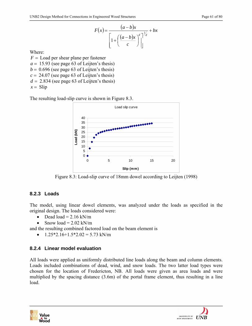
UNB2 Design Method for Connections in Engineered Wood Structures Page 61 of 80
( ) ( )( )
bx
cxba
xbaxFdd
+
⎥⎥⎦
⎤
⎢⎢⎣
⎡⎟⎠⎞
⎜⎝⎛ −
+
−= 1
1
Where: =F Load per shear plane per fastener =a 15.93 (see page 63 of Leijten’s thesis) =b 0.696 (see page 63 of Leijten’s thesis) =c 24.07 (see page 63 of Leijten’s thesis) =d 2.834 (see page 63 of Leijten’s thesis) =x Slip
The resulting load-slip curve is shown in Figure 8.3.
Load slip curve
05
10152025303540
0 5 10 15 20
Slip (mm)
Load
(kN
)
Figure 8.3: Load-slip curve of 18mm dowel according to Leijten (1998)
8.2.3 Loads The model, using linear dowel elements, was analyzed under the loads as specified in the original design. The loads considered were:
• Dead load = 2.16 kN/m • Snow load = 2.02 kN/m
and the resulting combined factored load on the beam element is • 1.25*2.16+1.5*2.02 = 5.73 kN/m
8.2.4 Linear model evaluation All loads were applied as uniformly distributed line loads along the beam and column elements. Loads included combinations of dead, wind, and snow loads. The two latter load types were chosen for the location of Fredericton, NB. All loads were given as area loads and were multiplied by the spacing distance (3.6m) of the portal frame element, thus resulting in a line load.

UNB2 Design Method for Connections in Engineered Wood Structures Page 62 of 80
Table 8.3: Applied loads** Load type CpCg* Area load Line load
(x3.6m) kN/m² kN/m² kN/m Dead D 0.6 2.16 Snow + Rain Ss+Sr 2.8 + 0.5 = 3.3 11.88 Wind W 0.37 From left side Left Wl 0.37 1.00 0.37 1.332 Right Wr 0.37 0.80 0.296 1.066 Roof Wro 0.37 -1.30 -0.481 -1.732 From right side Left Wl 0.37 -0.80 -0.296 -1.0566 Right Wr 0.37 -1.00 -0.37 -1.332 Roof Wro 0.37 -0.90 -0.333 -1.199 Internal pressures Cpi 0.37 -0.7 -0.259 -0.932 0.37 0.0 0 0 0.37 +0.7 0.259 0.932
*Wind coefficient reflecting the building surface. From NBCC. 8.2.4.1 **Wall loads considered positive in x (from left) direction, roof
loads considered positive in gravity direction. Load combinations and load factors considered as given by the NBCC were: 1.25* x D 1.25* x D+ 1.00 x (1.5 x S) 1.25* x D+ 1.00 x (1.5 x W) 1.25* x D+ 0.70 x (1.5 x S+1.5 x W) *Dead load factor =0.85 in case of load reversal All loads were applied as factored loads in order to ease comparison to design values and to reflect the reduced probability that all three loads occur simultaneously (factor 0.7). Based on the above load combinations, a total of 14 load cases were established as in Table 8.4. In case of the vertical loads on the columns, the load onto one side was equally distributed onto the columns pairs.
Table 8.4: Load cases 1 D 2 D+S 3.1 D+W,l,-0.7 3.2 D+W,l,0.0 3.3 D+W,l,+0.7 3.4 D+W,r,-0.7 3.5 D+W,r,0.0 3.6 D+W,r,+0.7 4.1 D+S+W,l,-0.7 4.2 D+S+W,l,0.0

UNB2 Design Method for Connections in Engineered Wood Structures Page 63 of 80
4.3 D+S+W,l,+0.7 4.4 D+S+W,r,-0.7 4.5 D+S+W,r,0.0 4.6 D+S+W,r,+0.7
The finite element results indicated that the governing static load case is load case 2, combined dead and snow load. Then, all routine structural designs and checking were performed based on the CSA Standard O86-01. From the design calculations, it was obtained that the structure would collapse if it were designed based on this load combination (dead + snow in Fredericton). The governing element would be the allowable shear load in the beam, which is exceeded by 26%. The forces and displacements at the connection elements at failure are listed in Table 8.5. It can be seen that these displacement values are far below the displacement values at ultimate load (failure) obtained from the test observation of Leijten (1998), Figure 8.3.
Table 8.5: Forces and displacements in connector shear planes, with linear dowel response
Shear plane Component Location Load Displacement N mm
Top left X top left 28100.02 1.5367 Bott left X bottom left 32079.79 2.579315 Top right X top right 41080.84 2.424528 Bott right X bottom right 45060.62 3.467143
Top left Z top left 21301.28 1.426816 Bott left Z bottom left 21365.47 1.446797 Top right Z top right 21308.17 1.427156 Bott right Z bottom right 21358.58 1.447149
Top left X/Z top left 35261.249 2.0969623 Bott left X/Z bottom left 38543.433 2.9573785 Top right X/Z top right 46278.219 2.8133806 Bott right X/Z bottom right 49866.305 3.7570362
8.2.5 Non-linear model evaluation The non-linear model was evaluated using the load-displacement relationship for an 18 mm dowel for the dowel elements. Because from the linear evaluation and the design checks it is known that the portal frame structure can bear a maximum vertical beam load, the nonlinear model was evaluated using this load as well. The forces and displacement at about failure load are listed in Table 8.6. A comparison of the forces and displacements in the dowels between the linear and non-linear model shows that that forces are lower, and displacements larger in the non-linear dowel connection, indicating lower connection stiffness. The maximum force in the dowel (Table 7) is about 26.9 kN with about 5 mm deformation. Looking at Figure 8.3, it can be seen that this deformation value is also below the deformation at ultimate load, which is 15 mm.

UNB2 Design Method for Connections in Engineered Wood Structures Page 64 of 80
Table 8.6: Forces and displacements in connector shear planes at around failure load, with non-
linear dowel response model
Shear plane Component Location Load Displacement N mm
Top left X top left 20051.16 1.617940 Bott left X bottom left -22742.85 -2.166456 Top right X top right 26138.98 -3.889375 Bott right X bottom right -26963.06 4.702258
Top left Z top left 20857.3 1.761863 Bott left Z bottom left 20968.97 1.781800 Top right Z top right 20857.3 1.761863 Bott right Z bottom right 20968.97 1.781800
Top left X/Z top left 28932.265 2.3920475 Bott left X/Z bottom left 30934.365 2.8050567 Top right X/Z top right 33440.593 4.2698242 Bott right X/Z bottom right 34157.054 5.0285228
8.3 Concluding Remarks
• From this simple case study, it can be concluded that at structural system failure, the deformations at the connections are likely to be rather smaller than deformations needed to mobilize the ultimate (peak) resistances of connections.
• It is doubtful that capacities of connections should be based on capacities of data from tests where connections are tested as components isolated from the rest of a structural system.
• More case studies with added complexity need to be conducted in the future to investigate further the system effect in structural wood systems.

UNB2 Design Method for Connections in Engineered Wood Structures Page 65 of 80
9 Conclusion and Recommendation Based on work performed in this project the following conclusions can be drawn.
• For connection design there is a need to characterize EWP into products that are high resistant to splitting at connections and those that are not. Design methods need to be consistent with this categorization.
• From EWP connection tests, Laminates Strand Lumber (LSL) has shown different failure patterns from other EWP that were investigated (i.e. Laminated Veneer Lumber (LVL) and Parallel Strand Lumber (PSL)) and solid wood.
• Under load perpendicular to the strong member axis most connections in EWP and solid wood exhibit brittle (cracking induced) failure at the fasteners. However, similar LSL connections can fail in the member rather than at the fasteners. Based on the test results, it is possible with some EWP (like LSL) to eliminate brittle failures at connections (even when relatively large diameter fasteners are used), thus solving problems that have severely limited structural capabilities of wood. This opens the door to very simple design methods for non-splitting EWP connections, and could increase market penetration especially into non-residential applications.
• Using steel tube fasteners instead of solid steel bolts is a highly effective means of avoiding brittle failures in connections, i.e. without the need to reinforce members, even in splitting prone EWP and lumber. Use of slotted-in steel plates and slender steel tube fasteners is the most efficient means of making EWP connections with high strength and high levels of ductility. For multiple fastener connections in EWP optimal end distances and spacing distances between steel tube fasteners (with outer diameters up to ¼ inch) can be much less than those required for similar solid wood connections.
• The test results for larger scale bolted connections indicate failure modes consistent with those from tests on small joints. Under load parallel to the member axis, typical Laminated Strand Lumber (LSL) connections fail in the net-section tension, while similar LVL connections fail by shear-out of rows of bolts. Also, LSL connection capacity is much closer to member strength compared to LVL and solid wood connections.
• Fracture predictions for EWP connections based on continuum representations, i.e. those that implement classical fracture mechanics, lead to underestimates of ultimate load in cases where brittle failure occurs. Continuum finite element models also gives inconsistent prediction of likely failure sites in multiple bolt EWP connections.
• Discrete element model using lattice network representations has shown a consistent result to replicate the real complex failure behaviours of EWP connections.
• Preliminary case study analysis indicates that it is may not be appropriate to base design capacities of connections on unconstrained behaviour as occurs in tests where connections are fully isolated from boundary conditions imposed by structural systems.
• Current test methods commonly employed to assess capacities on connections where there is ‘off member axis’ loading of EWP are flawed and new approaches are required.
• Groundwork has been laid for comprehensive improvements to connection design provisions with the Canadian design code for wood structures and parallel international documents.

UNB2 Design Method for Connections in Engineered Wood Structures Page 66 of 80
Recommended future work is: • Tests on typical full scale structural systems (e.g. trusses, frames) to investigate how
connection characteristics influence overall system behaviour, under different loading scenarios.
• Numerical case studies to investigate how connection characteristics influence overall system behaviour, under different loading scenarios.
• Development of design code provisions for wood structures that are fully consistent between sections in respect to expected functions for connections and how design capacities are assigned. Such provisions should be explicitly oriented toward system design instead of component design.
• Investigation of combinations of EWP and fasteners that fully exploit characteristics of various types of EWP, including creation of new high performance products.
Impacts/benefits to the wood industry resulting from findings of this project are:
• Creation of rational methods via which structural designers can exploit superior capabilities of modern EWP.
• Justification for applying EWP in construction situations beyond their use as simple substitutes for traditional solid wood products.
• Creation of technical data supporting non-residential construction applications of EWP. • Creation of novel steel tube fasteners for use with EWP.

UNB2 Design Method for Connections in Engineered Wood Structures Page 67 of 80
10 References Asiz, A., Smith I. (2005) New Generation of Timber Design Practices and Code Provisions Linking System and Connection Design, Proc. 38th Meeting of the CIB-W18, International Council for Research and Innovation in Building and Construction, Karlsruhe, Germany. ASTM. 2000. Standard Test Methods for Bolted Connections in Wood and Wood Base Products, D5652-95(2000), ASTM, West Conshohocken, PA.
Computer and Structures, Inc CSI (2005) Structural Analysis Program SAP2000 v10-User Reference, Berkeley, California.
Leijten, A. (1998) Densified Veneer Wood Reinforced Timber Joints with Expanded Tube Fasteners, Doctoral Dissertation, Delft Technological University, Delft, The Nederland.
Lhuede, E P., Gerrard C.M. and Macindoes L. 1989. Comparison of finite element analyses and experimental tests of bolted timber connections loaded perpendicular to the grain, Proceedings of Pacific Timber Engineering Conference, Institute of Professional Engineers, I: 315-321, Auckland, New Zealand.
Moses, D. (2002) Constitutive and Analytical Models for Structural Composites Lumber with Applications to Bolted Connections, Doctoral Dissertation, Department of Civil and Environmental Engineering, University of British Columbia, Vancouver, Canada. Murty, B. (2006) Wood and Engineered Wood Connections using Slotted Steel Plate(s) and Tight-Fitting Small Steel Tube Fasteners, Master Thesis, Faculty of Forestry and Environmental Management, University of New Brunswick, Fredericton, Canada. Murty, B., Asiz, A., Smith, I. (2006). Wood and Engineered Wood Product Connections Using Small Steel Tube Fasteners: An Experimental Study, Institute of Wood Science Journal, under review. Murty, B., Smith, I., Asiz, A. (2006). Wood and Engineered Wood Product Connections Using Small Steel Tube Fasteners: Applicability of European Yield Model, ASCE Journal of Materials in Civil Engineering, under review. Murty, B., Smith, I., Asiz, A. (2005). Design of Timber Connections with Slotted-in Steel Plates and Small Diameter Steel Tube Fasteners, International Council for Research and Innovation in Building and Construction – Working 18 Timber Structures (CIB-W18), Meeting 38, Paper No. 38-7-9, August 29 – 31, Karlsruhe, Germany. Pedersen, M.U., Clorius, C.O., Damkilde, L., Hoffmeyer, P., and Esklidsen, L. (1999) Dowel type connections with slotted-in steel plates, Working Commission W18-Timber Structure, Paper 32-7-8, International Council for Building Research Studies and Documentation, Rotterdam, The Netherlands.
UNB2 Design Method for Connections in Engineered Wood Structures Page 68 of 80
Smith, I., Foliente, G., Nguyen, M. and Syme, M. (2005) Capacities of dowel-type fastener joints in Australian pine, ASCE Journal of Materials in Civil Engineering, 17 (6): 664-675. Snow, M. (2006) Fracture Development in Engineered Wood Product Bolted Connections, Doctoral Dissertation, Faculty of Forestry and Environmental Management, University of New Brunswick, Fredericton, Canada. Snow, M., Asiz, A., Chen, Z., Chui, Y.H. (2006). North American Practices for Connections in Wood Construction, Progress in Structural Engineering and Materials, accepted for publication. Snow, M., Asiz, A., Smith, I. (2005). Numerical Modeling of Multiple-Bolt Engineered Wood Products, 33rd Annual Conference of the Canadian Society for Civil Engineers, June 2-4, Toronto, Canada. Snow, M., Smith, I., Asiz, A. (2004). Dowel Joints in Engineered Wood Products: Assessment of Simple Fracture Mechanics Models, International Council for Research and Innovation in Building and Construction – Working 18 Timber Structures (CIB-W18), Meeting 37, Paper No. 37-7-15, August 31 – Sept 3, Edinburgh, Scotland, UK. Snow, M., Asiz, A., Smith, I. (2004). Failure Behaviour of Single Dowel Connections in Engineered Wood Products, 5th Structural Specialty Conference of the Canadian Society for Civil Engineers, June 2-5, Saskatoon, Saskatchewan, Canada. Tan, D., Smith I. (1999) Failure in-the-Row Model for bolted timber connections, ASCE Journal of Structural Engineering, 5(3): 713-718. United Nations: Food and Agriculture Organization of the United Nations, Economic Commission for Europe. (2003) “Forest Products Annual Market Analysis: 2002-2004”. Timber Bulletin - Volume LVI, No. 3.

UNB2 Design Method for Connections in Engineered Wood Structures Page 69 of 80
Appendix I
New Generation of Timber Design Practices and Code Provisions Linking System and Connection Design

UNB2 Design Method for Connections in Engineered Wood Structures Page 70 of 80
New Generation of Timber Design Practices and Code Provisions Linking System and Connection Design
Andi Asiz and Ian Smith
University of New Brunswick, Canada
1. Introduction During the last several years the Canadian timber design code committee (Canadian Standard Association O86 Technical Committee) has been laying the groundwork for a major overhaul of the national model code CSA Standard O86-O1 ‘Engineered Design in Wood’ (CSA 2001a). Key issues are:
I. Need for consistency in the objectives, philosophy and technical details that underpin provisions of different sections of the code. For example, if the section dealing with seismic design of braced frames requires use of ductile connections, then the section dealing with detailed design of connections must provide guidance on how to achieve such mechanistic behaviour.
II. Explicit consideration of the relationships between design provision applicable to individual components (members and connections) and the performance of major structural subsystems and complete structural systems. As in other countries, structural codes in Canada are premised on sequential design of individual components. This premise is coupled with an expectation that if every component is ‘strong and stiff’ the complete structure will have adequate behaviour. Such an approach leads to great uncertainty about system behaviour at failure. Also, although arguably the current approach is conservative, solutions tend to be uneconomic.
III. Development of partial coefficients (load and resistance factors) in design equations that reflect ‘true’ rather than ‘nominal’ reliability levels.1 To date partial coefficients in the Canadian timber design code are calibrated to yield essentially the same solutions as were achieved from past Allowable Stress Design (ASD) codes. Structural reliability methods have been used, especially in connection with setting design resistances for small dimension lumber members. However, as the calibration point is always achieving safety indexes under partial coefficient design that maintain parity with ASD within selected calibration problems, it is simply a very fancy way to do so-called ‘soft code conversion’. For genuine progress under item II it is essential to deal with real reliability levels, i.e. not bother about parity with ASD solutions.
IV. Modernise the connection design provisions many of which have their origins in unrecorded committee decisions made in the order of 50 years ago, based on US studies for military purposes at around the time of the Second World War.
V. Rapid integration of new products, typically proprietary, into the market place. This requires the establishment of a framework and methods that ensures consistency in how
1 In Canada the terminology limit states design and partial coefficients design (known more frequently as Load and Resistance Factor Design, LRFD) are erroneously taken to be synonymous. Here the authors intend that limit states considerations be considered an integral part of partial coefficients design methods.

UNB2 Design Method for Connections in Engineered Wood Structures Page 71 of 80
design properties are assigned to old and new products. There have and will continue to be also be major changes in provisions of the National Building Code of Canada (NRC 2005), i.e. the model document that lays down general -- construction type independent -- design requirement, and specifies the magnitudes of environmental loads and load factors. The 2005 edition (to be published in September) will provides, for the first time, explicit statements of mandatory ‘design objectives’ and ‘functional statements’.2 The role of the timber code, and other material specific codes, is to provide a basis from which designers can produce solutions that satisfy various objectives listed in the building code. Implicit in items I to V listed above is recognition the potential that changes in the building code releases will only be fully harnessed by the timber construction sector if accompanied by major change in the timber design code. The last major overhaul of code provisions in Canada that relate to timber connections occurred in the early 1980’s. But what was done then was mostly concerned with reformatting information as the code as a whole was transformed from an ASD to a partial coefficients format. Here the need to revise connection design methods is employed as the tool for tying the sections of the national timber design code together, just as actual connections tie timber structures together. This touches on all of the issues I to V. Extensive use is made below of working documents produced by the University of New Brunswick’s Timber Engineering Group under the leadership of Professor Dr. Ian Smith. Specific consideration is given in those documents, and this one, to promoting design practices and provisions that:
• Make it transparent to designers what mode of failure governs the strength of particular connections, and how that relates to system behaviour.
• Embody probabilistic Load and Resistance Factor Design (LRFD) concepts. • Guide designers toward an appropriate choice of structural systems to resist given sets of
loading combinations. • Guide designers toward appropriate selection of wood and other structural materials. • Integrate design provisions specific to connections with those pertaining to the overall
system design. In the context of CSA Standard O86-O1 this amounts to integration of connection and general design requirements.
• Maximize possibilities for technical harmonization of Canadian and international practice.
What is outlined here is intended to be consistent with activities by other Canadian experts, especially those working on issues related to system behaviour. Although as yet so inconsistencies remain, work reported in the paper “Framework for lateral load design provisions for engineered wood structures in Canada” (Popovski and Karacabeyli 2005) is convergent with what is discussed here. The next three sections discuss the logic for new connection code provisions, general design code provisions that interrelate with design of connections, and current activities. 2. Provisions for Connection Chapter
2 Functional statements help users understand the reasons behind certain requirements.

UNB2 Design Method for Connections in Engineered Wood Structures Page 72 of 80
2.1 Global requirements
Concept here are based on the presumption that the code need specify as the first level decision what are and what are not acceptable modes of connection failure for particular combinations of Structure Type and Load Combination for Strength and Stability Limit Sates (Table 2.1). The second level of decision is what type of connection to select, knowing what are the acceptable failure modes (Table 2.2). Once appropriate options for connection are identified designers need rules for ‘sizing’ them (Section 2.2). The scope of the Connections Chapter should be limited to avoiding attainment of any strength or stability related limit state. When interpreting the permissible failure modes suggested in Table 2.1 it is important to recognize that load paths and/or load resisting mechanisms/components need not be the same for all the load combinations. Table 2.2 is illustrative and deals with only with connections that load fasteners or connectors lateral to the axis of the fastener or connector.
Table 2.1 – Proposed Permissible Failure Modes for Mechanical Connections Permissible Failure Modes
(Allowed nature of connection failures)
Structure Type
Load Combination (Comp. = companion) Brittle Ductile Bearing
φR ≥ 1.4D
r
a
a
φR ≥ 1.25D + 1.5L + Comp. r a a φR ≥ 1.25D + 1.5S + Comp. r a a φR ≥ 1.25D + 1.4W + Comp. r a a φR + effect 0.9D ≥ 1.4W or
1.5L or 1.5S r
a
r
φR ≥ 1.0D + 1.0E + Comp. r a r
Light-framing: not load-sharing
φR + effect 1.0D ≥ 1.0E r a r
φR ≥ 1.4D a
a
a
φR ≥ 1.25D + 1.5L + Comp. a a a φR ≥ 1.25D + 1.5S + Comp. a a a φR ≥ 1.25D + 1.4W + Comp. r a a φR + effect 0.9D ≥ 1.4W or
1.5L or 1.5S r
a
r
φR ≥ 1.0D + 1.0E + Comp. r a r
Light-framing: load-sharing and statically determinate
φR + effect 1.0D ≥ 1.0E r a r
φR ≥ 1.4D a
a
a
φR ≥ 1.25D + 1.5L + Comp. a a a φR ≥ 1.25D + 1.5S + Comp. a a a φR ≥ 1.25D + 1.4W + Comp. a a a φR + effect 0.9D ≥ 1.4W or
1.5L or 1.5S a
a
a
Light-framing: load sharing and statically indeterminate
φR ≥ 1.0D + 1.0E + Comp. r a r

UNB2 Design Method for Connections in Engineered Wood Structures Page 73 of 80
φR + effect 1.0D ≥ 1.0E r a r
φR ≥ 1.4D a
a
a
φR ≥ 1.25D + 1.5L + Comp. a a a φR ≥ 1.25D + 1.5S + Comp. a a a φR ≥ 1.25D + 1.4W + Comp. r a a φR + effect 0.9D ≥ 1.4W or
1.5L or 1.5S r
a
r
φR ≥ 1.0D + 1.0E + Comp. r a r
Heavy-framing: not self-bracing
φR + effect 1.0D ≥ 1.0E r a r
φR ≥ 1.4D r
a
a
φR ≥ 1.25D + 1.5L + Comp. r a a φR ≥ 1.25D + 1.5S + Comp. r a a φR ≥ 1.25D + 1.4W + Comp. r a a φR + effect 0.9D ≥ 1.4W or
1.5L or 1.5S r
a
r
φR ≥ 1.0D + 1.0E + Comp. r a r
Heavy-framing: self-bracing
φR + effect 1.0D ≥ 1.0E r a r
φR ≥ 1.4D r
a
a
φR ≥ 1.25D + 1.5L + Comp. r a a φR ≥ 1.25D + 1.5S + Comp. r a a φR ≥ 1.25D + 1.4W + Comp. r a a φR + effect 0.9D ≥ 1.4W or
1.5L or 1.5S r
a
r
φR ≥ 1.0D + 1.0E + Comp. r a r
Arches and shells
φR + effect 1.0D ≥ 1.0E r a r asignifies a failure mode is permissible, while r signifies a failure mode is not permissible. φR is factored resistance, D, L, S, W & E are effects dead, live occupancy, snow, wind and earthquake loads respectively. Load Combinations refers to cases specified in the building code (NRC 2005).
Table 2.2 – Possible Failure Modes According to Connection Type: Laterally loaded fasteners or connectors (B = brittle, C = bearing/compressive, D = ductile, EWP = Engineered Wood Products, OSB = Oriented Strand Board)
Connected Materials Connection type
Wood-to- Wood
Ply/OSB-to- wood
Steel- to- wood
Wood- to-concrete/masonry*
Wood- to- EWP+
Ply/OSB-to- EWP
Steel- to- EWP
Dowel fasteners
B, C, D B, D B, C, D B, C B, D B, D B, D

UNB2 Design Method for Connections in Engineered Wood Structures Page 74 of 80
Wood connectors
B n/a B, C, D n/a B n/a n/a
Truss-plates B, D n/a n/a n/a B, D n/a n/a Light-gauge framing products
B, C, D
n/a
n/a
n/a
B, C, D
n/a
n/a
Glued-in-rods
B, C, D n/a B, C, D B, C, D B, C, D n/a B, C, D
Carpentry B, C, D n/a n/a B, C B, C, D n/a n/a Other To be determined by testing (Section 2.2.2).
* If concrete or masonry is reinforced so that local failures cannot propagate, attaining ductile failures is possible. + For the purposes of connection design EWP’s can be thought of as falling into categories of splitting and non-splitting as determined via a standardized test protocol (on going work at University of New Brunswick). Connections with members of splitting EWP materials can exhibit catastrophic failures due to fracturing in EWP members. However, connections with non-splitting EWP materials cannot exhibit catastrophic failures due to fracturing in EWP members. n/a signifies not appropriate.
2.2 Sizing connections The reference unit for calculation is the full connection, and not a single fastener or connection as was the case formerly. 2.2.1 By calculation It is assumed that mechanics based models will be the basis for predicting both the characteristic ultimate load capacity and the associated failure mode. It is presumed that although most models will be based on explicit hand calculations (e.g. existing approach for connections with one bolt – Johansen type yield model), in some instances models will need to be hybrid (e.g. existing design approach for connections with ‘timber rivets’) or even empirical evidence (e.g. existing approach for connections with multiple bolts). There is no attempt to formulate and provide details of suitable models here but that topic is currently being worked on by researchers at the University of New Brunswick. Table 2.2.1 specifies the failure mechanisms to be considered for various types of connections. The predicted failure mode for a prospective connection detail is the failure mechanism associated with the minimum estimate of the characteristic ultimate load capacity. The table is very general in its present form and reflects mechanisms possible under arbitrary loading arrangements. In many practical situations a designer would only consider a subset of the listed mechanisms. Where the predicted governing failure mechanism is ductile and the associated characteristic ultimate load capacity is greater than 0.9 times the characteristic ultimate capacity for any alternative mechanism that is brittle, it should be assumed that failure mode would be brittle. However the original estimate for the characteristic ultimate load capacity, for the ductile mode, would still be the value adopted.
Table 2.2.1 – Possible Failure Mechanisms to be considered: Laterally loaded fasteners or connectors

UNB2 Design Method for Connections in Engineered Wood Structures Page 75 of 80
Possible Failure Mechanisms Connection type
Yielding (EYM)
Tear-out Shear in-the-row
Opening fracture
Shearing fracture
Pull-out Bearing
Dowel fasteners
a
a
a
a
a
n/a
n/a
Wood connectors
a
a
a
a
a
n/a
n/a
Truss-plates a a a a* a* a n/a Light-gauge framing products
a
n/a
n/a
a*
a*
a
a
Glued-in-rods
a
n/a
n/a
a
a
a
a
Carpentry n/a n/a n/a a a a a Other To be determined by testing (Section 2.2.2). * the facture could be in either wood or metal. 2.2.2 From test data ISO test methods are preferred to promote uniformity in practices and maximize opportunities for exchange of data with foreign colleagues. Tests should be realistic replicating as closely as possible the geometric and loading arrangement, load waveform and frequency, and material conditioning applicable to field situations. The number of test replicates should be enough to reliably characterize average and variability in parameters that characterize any connection’s structural response. The necessary combination of loading regimes will vary depending on the type of connection and the application. Loading regimes that can be applicable are: sustained loads causing static fatigue, fluctuating loads causing low-cycle fatigue, fluctuating loads causing high-cycle fatigue and single or repetitive impact loads. Within cyclic regimes the loading can be applied under either displacement control (seismic load scenarios), or load control (wind loads scenarios). To date most tests have been carried out using so-called static load where a monotonic load is increased steadily at a rate that causes failure in about 0.1 hours. Static tests mostly employ displacement control. Such load is virtually irrelevant to field applications of connections, but is the simplest and cheapest regime to apply and within the capability of all credible test facilities. The main reason for including static tests within any future research plan is that they provide a basis for comparing results with historical data. Employing realistic loading conditions is prerequisite to proper ‘sizing’ of connections (and other structural timber components). The following procedure enables calculation of the Standardized Specified Resistance (Rs) from test data, in a manner consistent with established Canadian practice (CSA 2001b). STEP 1: The 5th percentile strengths at 75 % confidence (R0.05,0.75) is calculated as:
R0.05,0.75 = Cf R0.05,data where
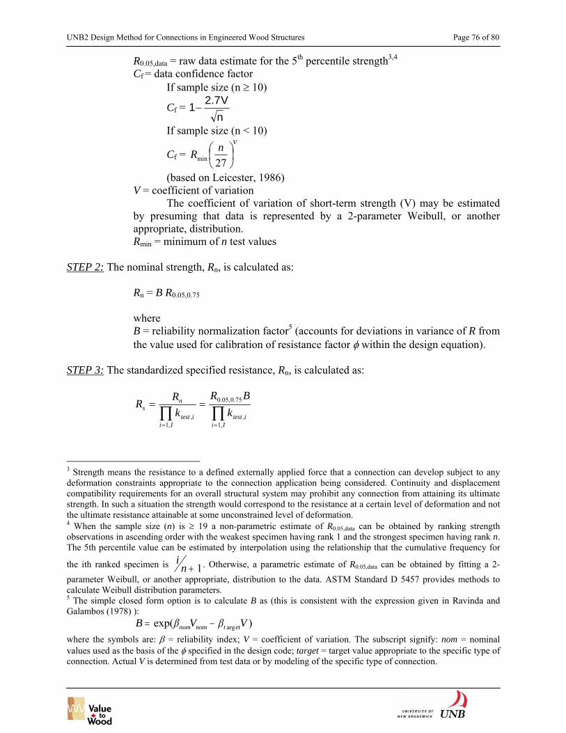
UNB2 Design Method for Connections in Engineered Wood Structures Page 76 of 80
R0.05,data = raw data estimate for the 5th percentile strength3,4 Cf = data confidence factor
If sample size (n ≥ 10)
Cf = nV7.21−
If sample size (n < 10)
Cf = VnR ⎟
⎠⎞
⎜⎝⎛
27min
(based on Leicester, 1986) V = coefficient of variation The coefficient of variation of short-term strength (V) may be estimated by presuming that data is represented by a 2-parameter Weibull, or another appropriate, distribution.
Rmin = minimum of n test values STEP 2: The nominal strength, Rn, is calculated as:
Rn = B R0.05,0.75 where B = reliability normalization factor5 (accounts for deviations in variance of R from the value used for calibration of resistance factor φ within the design equation).
STEP 3: The standardized specified resistance, Rn, is calculated as:
R Rk
R Bks
n
test ii I
test ii I
= =
= =∏ ∏,
,
. , .
,,1
0 05 0 75
1
3 Strength means the resistance to a defined externally applied force that a connection can develop subject to any deformation constraints appropriate to the connection application being considered. Continuity and displacement compatibility requirements for an overall structural system may prohibit any connection from attaining its ultimate strength. In such a situation the strength would correspond to the resistance at a certain level of deformation and not the ultimate resistance attainable at some unconstrained level of deformation. 4 When the sample size (n) is ≥ 19 a non-parametric estimate of R0.05,data can be obtained by ranking strength observations in ascending order with the weakest specimen having rank 1 and the strongest specimen having rank n. The 5th percentile value can be estimated by interpolation using the relationship that the cumulative frequency for
the ith ranked specimen is in + 1. Otherwise, a parametric estimate of R0.05,data can be obtained by fitting a 2-
parameter Weibull, or another appropriate, distribution to the data. ASTM Standard D 5457 provides methods to calculate Weibull distribution parameters. 5 The simple closed form option is to calculate B as (this is consistent with the expression given in Ravinda and Galambos (1978) ): B V Vnom nom t et= −exp( )argβ β
where the symbols are: β = reliability index; V = coefficient of variation. The subscript signify: nom = nominal values used as the basis of the φ specified in the design code; target = target value appropriate to the specific type of connection. Actual V is determined from test data or by modeling of the specific type of connection.

UNB2 Design Method for Connections in Engineered Wood Structures Page 77 of 80
where for example: ktest, duration of loading might be given the value 1.25 = 1/0.8 if resistance for ‘standard term’ loading is 0.8 time the short-term test strength.
For connections that must resist earthquake combinations, and wind loading combinations causing force reversals, the above can be supplemented by assessment of the ductility class (Popovski and Karacabeyli 2005). Ductility classification of connections by test is simple. Although experiments tend to be expensive, they are probably the most viable approach as few people have the capabilities needed to do ductility classifications via models. 3. Provisions for General Design Chapter 3.1 Control of failure modes Implicit to the strategy embodied in Section 2 is that designers should not be permitted unfettered choice of combinations of member type and connections for structural arrangements prone to disproportionate or unstable development of local into whole system failures. For some loading combinations it is critical that the connections fail first and not the members, and that even when some connections have failed there is still continuity in the original or an alternative load path(s). Under earthquake and strong wind loading scenarios, this is achieved via connections having adequate ductility. It is presumed here that attaining adequate ductility is a primary requirement under loading combinations that involve earthquake effects and/or wind effects that lead to force reversals.
General design provisions should require attainment of a certain level of ductility and fatigue life classifications by whole systems and critical connections. What is done needs to be consistent with provisions being developed by the CSA O86 Seismic Design Taskforce (Popovski and Karacabeyli 2005).
The approach underpinning Tables 2.1 and 2.2, and any ductility and fatigue life requirements are part of a strategy for ensuring that designers are guided toward appropriate choices of connections under given loading combinations. However, in themselves these provide no surety that whole systems will be unlikely to be governed by catastrophic member failure. It is necessary to also control likelihood of catastrophic member failures, with the Capacity Design approach (Section 3.2) being a suitable vehicle.
3.2 Capacity design
The Capacity Design concept has been used for a number of years to design reinforced concrete structures against the effects of seismic loads (Paulay, 1981). The idea is to make it most likely that failure will be in the connections, and not the members, Fig. 1. Chui and Smith (1993) made a preliminary study of how the method might be applied in seismic design of timber structures and concluded that it is viable.

UNB2 Design Method for Connections in Engineered Wood Structures Page 78 of 80
It is important to recognize that reasons for enforcing that failures are most likely to occur in the connections would not be the same in the cases of wind and seismic design. Under wind load conditions, design for ductile failure in the connections is desirable because this promotes redistribution of forces between components and subassemblies. This is one of the means of avoiding progressive and disproportionate damage in structural systems. In seismic design, ductile failure in the connections is desired because mechanical connections are the only significant sources of ductility and energy absorption during cyclic loading.
Because of the complexity of many wood-based structural systems, the behaviour of subsystems (diaphragms, shear walls, roof panels and trusses) is hard to predict and thus forces in individual wood elements are not usually predicted with much certainty. However, if load paths are clearly defined within a structural system it is possible to predict the forces in the connections between subsystems with relatively good accuracy, e.g. between the roof and walls, between the walls and foundation. The connections between subsystems often also happen to be locations prone to failure during high wind or seismic events. Capacities of properly designed connections can be controlled to be less variable than the capacities of timber members or subsystems they join (e.g., Larsen and Jensen 2000). Thus, the strength of a whole structural system should be able to be predicted with a high degree of certainty using a capacity design type concept.
The general design equations within CSA Standard O86-O1 for implementation of Capacity Design would take the form:
∑ ≤ LkCLC RsLoadEffect ,,,φ and
kMMUkCUC RR ,,,, φφ ≤
where
Prob.density
Force
(Wind/ E’quake)Member Resistance, R
M
R
Fig. 1: Logic of the Capacity Design concept
Force
(Wind/ E’quake)Member
J
Force
Load Effect(Wind/ E’quake)
Member
Joint Resistance
DESIGN EQUALITY
DESIGN EQUALITY
Prob.density
Force
(Wind/ E’quake)Member Resistance, R
M
R
Fig. 1: Logic of the Capacity Design concept
Force
(Wind/ E’quake)Member
J
Force
Load Effect(Wind/ E’quake)
Member
Joint Resistance
DESIGN EQUALITY
DESIGN EQUALITY

UNB2 Design Method for Connections in Engineered Wood Structures Page 79 of 80
φC,L = connection resistance factor associated with the lower characteristic connection strength RC,k,L (typically the 5 percentile value, RC,0.05),
φC,U = connection resistance factor associated with the upper characteristic connection strength RC,k,U (typically the 95 percentile value, RC,0.95),
φM = member resistance factor associated with the lower characteristic member strength RM,k (typically the 5 percentile value, RM,0.05).
Implicitly, the capacity design concept presumes that the design equations are calibrated using structural reliability concepts. As already discussed (Section 1), to be meaningful methods have to be based on true rather than nominal reliability. Neither member nor connection capacities can any longer be based on a soft conversion from ASD to partial coefficients design (LRFD or what is wrongly called Limit States Design in Canada).
4. Current Activities Reliability analysis of structural timber systems and connections is being conducted at the University of New Brunswick using representative Case Studies. The intent is that within the next year UNB researchers in collaboration with researchers from Forintek Canada Corp. will propose a framework for a Canadian timber design code that is fully consistent with respect to design of structural systems (and large subsystems) and connection design. Ongoing work at UNB is addressing:
• Consistency in reliability approaches: This refers to consistency between the timber design code (CSA Standard O86-01) and the National Building Code of Canada that defines material independent characteristic loads and load factors.
• Definition of failure of a connection: This recognises that failure processes in structural connections must obey overall system requirements for continuity and compatibility (system deformations will not permit various connections to attain excessive deformation). In practical terms this implies that it is inappropriate to simply assume that the reference strength of a connection should equal say the ultimate connection load, or perhaps the “yield load”, as observed in tests on isolated connections. The same argument should be applied to members in composite and built-up timber construction, e.g. light-frame construction.
• Definition of the unit of reference: This refers to whether connection reliability is to be controlled at the level of a joint (one end of one member), a member (they usually have a joint at each end), a connection (several members can be join at a connection), a subsystem (e.g. truss), or a building. Nominally current practices relate to the level of a joint. However, this has had limited reliability implications because traditionally ASD) capacities of connections were assigned based on the concept of controlling the extent of deformation in connections.
• Weak or strong connections: Traditionally under ASD connections were strong elements and tended to be over-designed, but this implies that failures are forced to occur in members and hence that system failures will be brittle. Philosophically at least, designers should be given opportunity to select whether to create connections that are, for example, weak and ductile or strong and stiff.

UNB2 Design Method for Connections in Engineered Wood Structures Page 80 of 80
5. Concluding Comment Canada is on the cusp of being able to implement a new generation of timber design codes. Although not discussed here, the biggest challenge in achieving major advances is counteracting inertia in a code development system that is not well geared to radical change. The authors invite international colleagues to comment, share ideas and participate in the necessary tasks. References CSA. 2001a. Engineering design in wood, Canadian Standard 086-01, Canadian Standard Association, Toronto, Canada. CSA. 2001b. Standard practice relating specified strengths of structural members to characteristic structural properties, Supplemental document, CSAO86 Technical Committee, Canadian Standard Association, Toronto, Canada. Chui, Y.H., Smith, I. 1993. Capacity design of wood structures, Proc. Annual Conf. Canadian Society for Civil Engineering, II: 365-374. Larsen, H.J., Jensen J.L. 2000. Influence of semi-rigidity of joints on the behaviour of timber structures, Progress in Struct. Eng. and Materials, 2: 267-277. Leicester, R.H. 1986. Confidence in estimates of characteristic values, Proc. 19th Meeting CIB-W18, International Council for Research and Innovation in Building and Construction, Rotterdam, The Netherlands. NRC. 2005. National Building Code, National Research Council, Ottawa, Canada. Paulay, T. 1981. Developments in the seismic design of reinforced concrete frames in New Zealand, Canadian J. Civil Eng, 8: 91-113. Popovski, M., and Karacabeyli, E. 2005. Framework for lateral load design provisions for engineered wood structures in Canada, Proc. 38th Meeting CIB-W18, International Council for Research and Innovation in Building and Construction, Karlsruhe, Germany. Ravinda, M.K., and Galambos, T.V. 1978. Load and resistance factor design for steel”, ASCE J. Structural Division, 104 (ST9): 1337-1353.