design, modeling and characterization of triply …
TRANSCRIPT
DESIGN, MODELING AND CHARACTERIZATION OF TRIPLY PERIODIC MINIMAL SURFACE HEAT EXCHANGERS WITH ADDITIVE MANUFACTURING
Hao Peng1*, Feng Gao2, and Wenjing Hu3
1. ITAMCO & Atlas3D2. Dept. of Chemical and Biomolecular Engineering, University of Notre Dame3. Dept. of Applied and Computational Mathematics and Statistics, University of Notre Dame*Corresponding author: [email protected]
Abstract Next-generation power plants will generate heated fluids at significantly higher
temperatures than current-generation power plants, which challenges the state-of-the-art heat exchanger design. In this study triply periodic minimal surfaces were combined with additive manufacturing for next-generation heat exchanger design. Triply periodic minimal surfacesseparate three-dimensional space into two interpenetrating channels, creating high surface area to volume ratios and low hydrodynamic resistance. Parametric design of triply periodic minimal surface heat exchanger is straightforward because they are governed by simple implicit functions with parameters such as periodic length and offset parameter. In this study a design workflow was developed to streamline the design of triply periodic minimal surface heat exchangers and a numerical model was developed to optimize triply periodic minimal surface heat exchanger design for optimal performance. Finally, the optimized triply periodic minimal surface heat exchanger was printed with EOS M290 DMLS machine and the performance was tested by experiment.
Keywords: triply periodic minimal surface, additive manufacturing, heat exchanger, lattice structure
Introduction 1.1 State-of-the-art Heat Exchangers
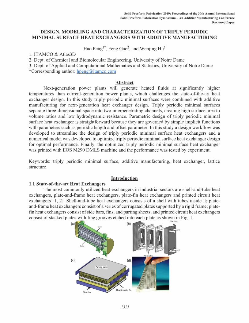
The most commonly utilized heat exchangers in industrial sectors are shell-and-tube heat exchangers, plate-and-frame heat exchangers, plate-fin heat exchangers and printed circuit heat exchangers [1, 2]. Shell-and-tube heat exchangers consists of a shell with tubes inside it; plate-and-frame heat exchangers consist of a series of corrugated plates supported by a rigid frame; plate-fin heat exchangers consist of side bars, fins, and parting sheets; and printed circuit heat exchangers consist of stacked plates with fine grooves etched into each plate as shown in Fig. 1.
2325
Solid Freeform Fabrication 2019: Proceedings of the 30th Annual InternationalSolid Freeform Fabrication Symposium – An Additive Manufacturing Conference
Reviewed Paper
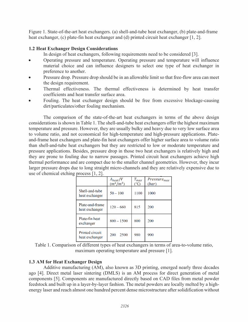
Figure 1. State-of-the-art heat exchangers. (a) shell-and-tube heat exchanger, (b) plate-and-frame heat exchanger, (c) plate-fin heat exchanger and (d) printed circuit heat exchanger [1, 2].
1.2 Heat Exchanger Design Considerations In design of heat exchangers, following requirements need to be considered [3]. Operating pressure and temperature. Operating pressure and temperature will influencematerial choice and can influence designers to select one type of heat exchanger inpreference to another.Pressure drop. Pressure drop should be in an allowable limit so that free-flow area can meetthe design requirement.Thermal effectiveness. The thermal effectiveness is determined by heat transfercoefficients and heat transfer surface area.Fouling. The heat exchanger design should be free from excessive blockage-causingdirt/particulates/other fouling mechanism.
The comparison of the state-of-the-art heat exchangers in terms of the above design considerations is shown in Table 1. The shell-and-tube heat exchangers offer the highest maximum temperature and pressure. However, they are usually bulky and heavy due to very low surface area to volume ratio, and not economical for high-temperature and high-pressure applications. Plate-and-frame heat exchangers and plate-fin heat exchangers offer higher surface area to volume ratio than shell-and-tube heat exchangers but they are restricted to low or moderate temperature and pressure applications. Besides, pressure drop in those two heat exchangers is relatively high and they are prone to fouling due to narrow passages. Printed circuit heat exchangers achieve high thermal performance and are compact due to the smaller channel geometries. However, they incur larger pressure drops due to long straight micro-channels and they are relatively expensive due to use of chemical etching process [1, 2].
Table 1. Comparison of different types of heat exchangers in terms of area-to-volume ratio, maximum operating temperature and pressure [1].
1.3 AM for Heat Exchanger Design Additive manufacturing (AM), also known as 3D printing, emerged nearly three decades
ago [4]. Direct metal laser sintering (DMLS) is an AM process for direct generation of metal components [5]. Components are manufactured directly based on CAD files from metal powder feedstock and built up in a layer-by-layer fashion. The metal powders are locally melted by a high-energy laser and reach almost one hundred percent dense microstructure after solidification without
2326
A11eatfV Tmax Pressuremax (m2 /m3) (OC) (bar)
Shell-and-tube 50 - 100 11 00 1000
heat exchanger
Plate-and-frame 120 - 660 815 200
heat exchanger
Plate-fi n heat 800 - 1500 800 200
exchanger
Printed circuit 200 - 2500 980 900
heat exchanger
any additional steps. Thanks to the layer-wise buildup, this process provides components of virtually any shape with almost unlimited freedom of design, and enables manufacturing of complex geometries and internal structures which are not possible with traditional manufacturing techniques. In addition, AM offers almost unlimited freedom of design, and moreover, a variety of materials such as 17-4 stainless steel, Inconel 625 and 718, aluminum AlSi10Mg and titaniumTi6Al4V can be chosen for different applications.
Heat exchangers are a type of components where AM can provide significant advantages in function and efficiency. Figure 2(a) is a multi-furcating heat exchanger designed at General Electric Global Research [1]. The best results showed that the heat exchanger met the pressure drop and heat transfer design requirement with 66% lower weight and 50% lower volume than the conventional heat exchangers. Figure 2(b) shows a heat exchanger with a large number of intricate channels and complex internal structures which are designed to maximize surface area to volume ratio for high efficiency of heat transfer [6]. Figure 2(c) shows a heat exchanger designed and built by EOS® with AM technology. The heat exchanger is self-supporting with integrated cooling fins on outside surfaces [7].
Figure 2. (a) Multi-furcating heat exchanger, (b) heat exchanger design with intricate inner channels, and (c) heat exchanger designed by EOS.
Triply periodic minimal surface heat exchanger (TPMS-HX) is a new type of heat exchanger which is only possible with AM. The concept of applying TPMS to heat and mass transfer devices was first introduced by Slaughter [8] in 2003. The concept was later expanded by Ryan [9] in 2013. Various types of TPMS were discussed including the Schwartz’s D surface, Schwartz’s P surface, Schoen’s Gyroid Surface and others. However, those studies only stay on conceptual level. Recently Nguyen and et al. [10] presented a study on TPMS-HX used in s-CO2 power cycles. Finite element (FEM) simulation was applied to analyze the flow pattern in a simple Gyroid TPMS structure. It was reported heat transfer was improved by a factor of 10-100 in comparison to micro-channel heat exchangers. Chandrasekaran [11] performed an experimental study on Schwartz’s D TPMS-HX. The geometry of the TPMS-HX was a simple cube and the material used was Nylon 12. To the best of the authors’ knowledge, existing studies on TPMS-HXare focused on simple cube- or block-type geometries and no metal TPMS-HX is investigated experimentally. This limitation is possibly due to the difficulties of design and manufacturing ofcomplex TPMS-HX geometries by traditional CAD software and manufacturing techniques. In this manuscript, the design, modeling and characterization of an industrial TPMS-HX is presented. The influence of design parameters of TPMS-HX on the performance of fluid flow and heat transfer is studied by simulation and an EOS M290 powder bed fusion AM machine is employed to build the TPMS-HX for performance testing. The structure of this manuscript is arranged as follows. Section 1 discusses the general design consideration of heat exchanger and the use of AM for TPMS-HX. Section 2 introduces the characteristic of TPMS-HX and the design workflow of
2327
(a)
TPMS-HX. Section 3 presents the simulation of TPMS-HX with COMSOL Multiphysics®. The fluid pattern and heat transfer efficiency for different types of TPMS-HX is analyzed. Section 4 shows the experimental studies on the proposed TPMS-HX.
Triply Periodic Minimal Surface Heat Exchanger Design 2.1 Triply periodic minimal surface (TPMS)
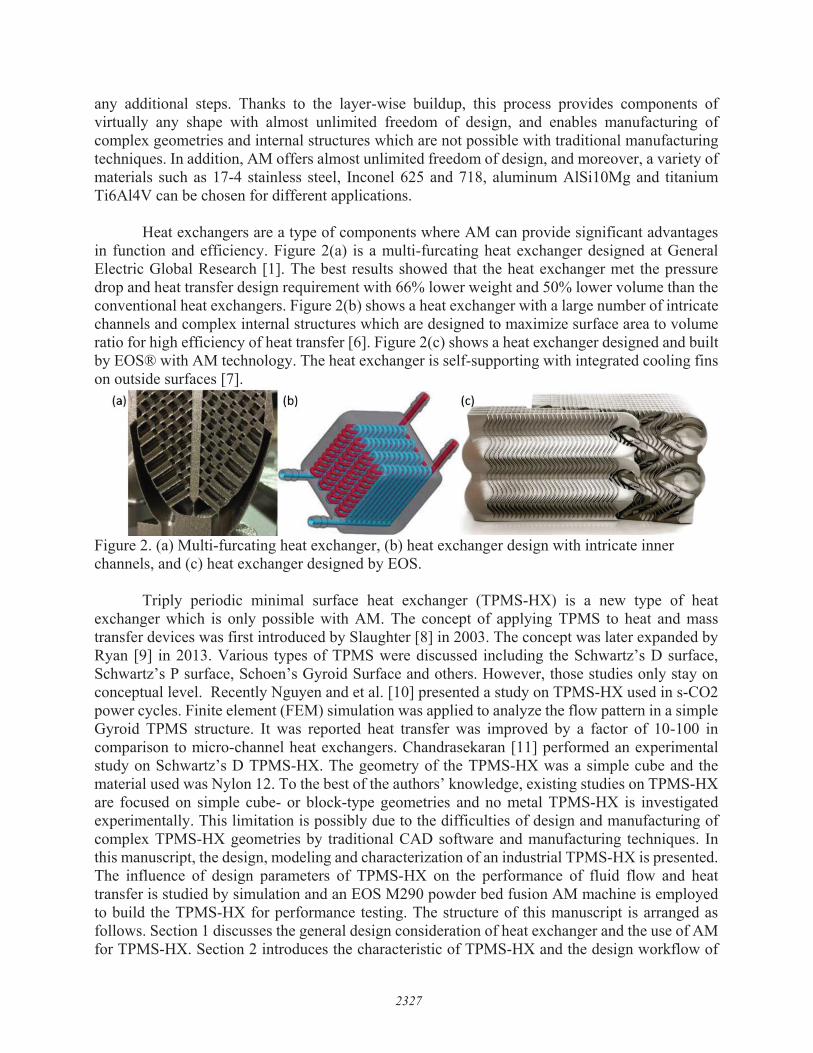
TPMS is defined as surfaces of zero mean curvature, meaning that the sum of the principal curvatures at each point is zero. TPMS is a surface minimizes its area with a fixed boundary curve. MS has been mathematically created using level-set equations [12]. These equations consist of implicit trigonometric functions that define an isosurface. Classical examples of TPMSs include Schwartz surface, Gyroid surface and Diamond surface which can be characterized with implicit functions as follows [13].
2 2 2Schwartz: cos cos cosx y z PL L L
, (1.1)
2 2 2 2 2 2Gyroid : cos sin cos sin cos sinx y y z z x PL L L L L L
, (1.2)
2 2 2 2 2 2Diamond : sin sin sin sin cos cos
2 2 2 2 2 2cos sin cos cos cos sin
x y z x y zL L L L L L
x y z x y z PL L L L L L
, (1.3)
where L is the periodic length and P is the offset parameter. Figure 3 shows the three types of TPMSs in one periodic length with zero offset parameter.
Figure 3. TPMSs in one periodic length: (a) Schwartz surface, (b) Gyroid surface and (c) Diamond surface.
2.2 Characteristics of TPMS The following unique features of TPMSs make them promising in the next-generation
heat exchanger design. (1) TPMSs divide a three-dimensional (3D) domain into two separated but interpenetrating channels which provides large surface area to volume ratio. As such, twoflows with different temperatures can pass through the separated channels and exchange heat efficiently. Figure 3 shows how cubic domains are separated into Channel A and Channel B byTPMSs. Figure 4 shows that surface area to volume ratio of a Gyroid triply periodic minimal surface increases exponentially with decreasing periodic length and reaches up to 3000 m2/m3
with periodic length of 1 mm. The surface area can be calculated with 22
1 z zS dxdyx y
. (2)
2328

(2) The mean curvature is zero at any point on a TPMS and each separated channel is inter-connected in all directions. Therefore, the flow is free to move in any direction and thehydrodynamic resistance and pressure drop in TPMS is low. (3) TPMSs create complex flowpattern which will enhance heat transfer efficiency and prevent fouling. For example, a helical-fashion flow pattern is generated in a Gyroid TPMS. The vortex in the flow will help increaseheat transfer coefficient and prevent fouling by removing dirt or particulates attached to theGyorid surface. (4) TPMSs exhibit high structural integrity and can realize pressure equalization[8]. TPMS-HX is usually manufactured by AM as a whole piece without welding or brazing.Also, pressure exerted on two sides of a triply periodic minimal surface tends to equalize.Therefore, they can survive demanding working conditions such as high temperature andpressure. (5) TPMSs are governed by simple implicit functions parametric design of TPMS-HXis straightforward. (6) TPMSs are self-supporting structures and the time-consuming supportremoval process can be avoided after the AM process.
Figure 4. Surface area to volume ratio of a Gyroid surface.
2.3 TPMS-HX Design Considerations To achieve optimal heat transfer performance, design parameters of TPMS-HX such as
type of triply periodic minimal surface, periodic length, wall thickness, triply periodic minimal surface orientation and offset parameter can be adjusted to accommodate various application scenarios.
Type of TPMS: The first step in TPMS-HX design is to determine the proper type of triplyperiodic minimal surface. There are many types of TPMSs and the most classical ones areSchwartz surfaces, Gyroid surfaces and Diamond surface. Because each type of triplyperiodic minimal surface gives a unique flow pattern, the heat transfer and pressure dropperformance will be also different. For example, the Schwartz surface may give a lowpressure drop due to its large straight channels along x, y and z direction. However, theheat transfer performance of a Schwartz TPMS-HX may not as good as a Gyroid TPMS-HX because heat transfer in Gyroid surface can be enhanced by its helical-fashion flowpattern. In addition, types of triply periodic minimal surface will influence themanufacturability of TPMS-HX as well as the maximum operating temperature andpressure.Periodic Length and Wall Thickness: The periodic length and wall thickness of TPMS-HXwill influence not only the manufacturability but also the heat transfer performance ofTPMS-HX. On one hand, the surface area to volume ratio of TPMS-HX increasesexponentially with decreasing periodic length as shown by Fig. 4. On the other hand, smallperiodic length means smaller characteristic dimension which will induce larger pressure
2329
e 3 0
~ ;::.2.5 .51 e 2 e " 0 1.5 0 > g
" f 0 d
" 0
" ~ 0.5 Cl)
0 0 0 0 0
0
2 3 4 5 6 7 8 9 Periodic length (mm)
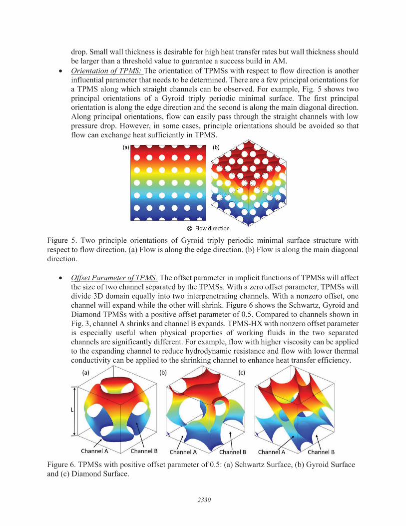
drop. Small wall thickness is desirable for high heat transfer rates but wall thickness should be larger than a threshold value to guarantee a success build in AM.Orientation of TPMS: The orientation of TPMSs with respect to flow direction is anotherinfluential parameter that needs to be determined. There are a few principal orientations fora TPMS along which straight channels can be observed. For example, Fig. 5 shows twoprincipal orientations of a Gyroid triply periodic minimal surface. The first principalorientation is along the edge direction and the second is along the main diagonal direction.Along principal orientations, flow can easily pass through the straight channels with lowpressure drop. However, in some cases, principle orientations should be avoided so thatflow can exchange heat sufficiently in TPMS.
Figure 5. Two principle orientations of Gyroid triply periodic minimal surface structure with respect to flow direction. (a) Flow is along the edge direction. (b) Flow is along the main diagonal direction.
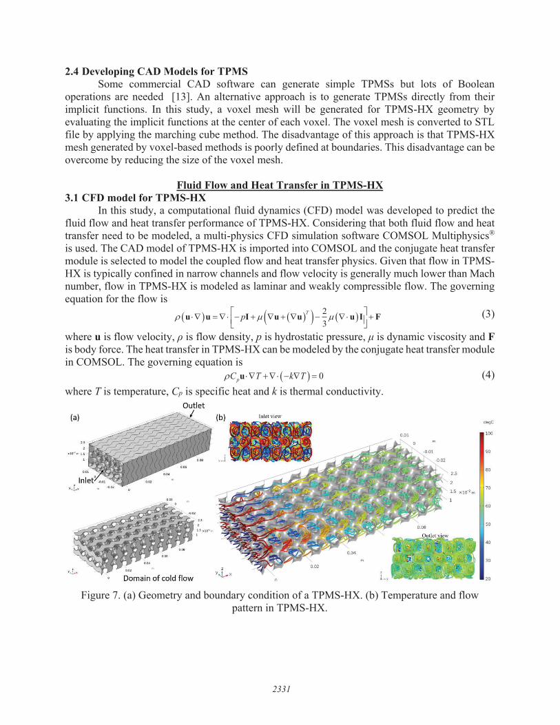
Offset Parameter of TPMS: The offset parameter in implicit functions of TPMSs will affectthe size of two channel separated by the TPMSs. With a zero offset parameter, TPMSs willdivide 3D domain equally into two interpenetrating channels. With a nonzero offset, onechannel will expand while the other will shrink. Figure 6 shows the Schwartz, Gyroid andDiamond TPMSs with a positive offset parameter of 0.5. Compared to channels shown inFig. 3, channel A shrinks and channel B expands. TPMS-HX with nonzero offset parameteris especially useful when physical properties of working fluids in the two separatedchannels are significantly different. For example, flow with higher viscosity can be appliedto the expanding channel to reduce hydrodynamic resistance and flow with lower thermalconductivity can be applied to the shrinking channel to enhance heat transfer efficiency.
Figure 6. TPMSs with positive offset parameter of 0.5: (a) Schwartz Surface, (b) Gyroid Surface and (c) Diamond Surface.
2330
(a)
® Flow direction
2.4 Developing CAD Models for TPMS Some commercial CAD software can generate simple TPMSs but lots of Boolean
operations are needed [13]. An alternative approach is to generate TPMSs directly from their implicit functions. In this study, a voxel mesh will be generated for TPMS-HX geometry by evaluating the implicit functions at the center of each voxel. The voxel mesh is converted to STL file by applying the marching cube method. The disadvantage of this approach is that TPMS-HXmesh generated by voxel-based methods is poorly defined at boundaries. This disadvantage can be overcome by reducing the size of the voxel mesh.
Fluid Flow and Heat Transfer in TPMS-HX3.1 CFD model for TPMS-HX
In this study, a computational fluid dynamics (CFD) model was developed to predict the fluid flow and heat transfer performance of TPMS-HX. Considering that both fluid flow and heat transfer need to be modeled, a multi-physics CFD simulation software COMSOL Multiphysics®
is used. The CAD model of TPMS-HX is imported into COMSOL and the conjugate heat transfer module is selected to model the coupled flow and heat transfer physics. Given that flow in TPMS-HX is typically confined in narrow channels and flow velocity is generally much lower than Mach number, flow in TPMS-HX is modeled as laminar and weakly compressible flow. The governing equation for the flow is
23
Tpu u I u u u I F (3)
where u is flow velocity, ρ is flow density, p is hydrostatic pressure, μ is dynamic viscosity and Fis body force. The heat transfer in TPMS-HX can be modeled by the conjugate heat transfer module in COMSOL. The governing equation is
0pC T k Tu (4) where T is temperature, Cp is specific heat and k is thermal conductivity.
Figure 7. (a) Geometry and boundary condition of a TPMS-HX. (b) Temperature and flow pattern in TPMS-HX.
2331
(b) Inlet view
0.01
Domain of cold flow
2.5
d,oC
100
90
80
70
60
50
40
30
20
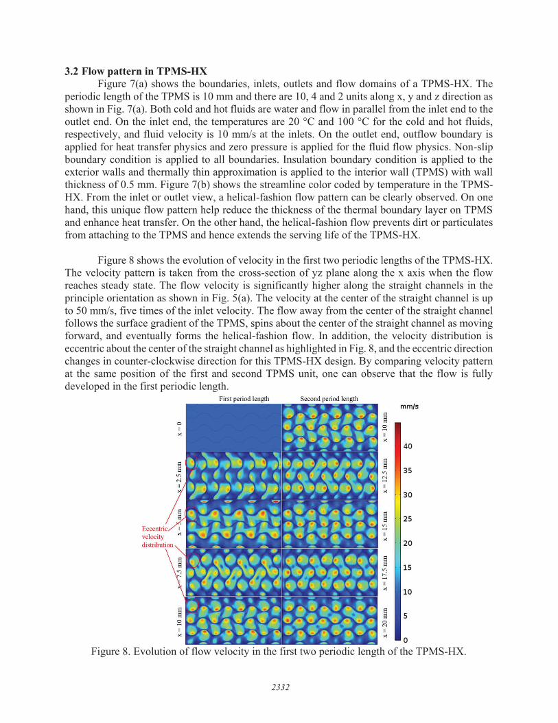
3.2 Flow pattern in TPMS-HXFigure 7(a) shows the boundaries, inlets, outlets and flow domains of a TPMS-HX. The
periodic length of the TPMS is 10 mm and there are 10, 4 and 2 units along x, y and z direction as shown in Fig. 7(a). Both cold and hot fluids are water and flow in parallel from the inlet end to the outlet end. On the inlet end, the temperatures are 20 °C and 100 °C for the cold and hot fluids, respectively, and fluid velocity is 10 mm/s at the inlets. On the outlet end, outflow boundary is applied for heat transfer physics and zero pressure is applied for the fluid flow physics. Non-slip boundary condition is applied to all boundaries. Insulation boundary condition is applied to the exterior walls and thermally thin approximation is applied to the interior wall (TPMS) with wall thickness of 0.5 mm. Figure 7(b) shows the streamline color coded by temperature in the TPMS-HX. From the inlet or outlet view, a helical-fashion flow pattern can be clearly observed. On one hand, this unique flow pattern help reduce the thickness of the thermal boundary layer on TPMS and enhance heat transfer. On the other hand, the helical-fashion flow prevents dirt or particulates from attaching to the TPMS and hence extends the serving life of the TPMS-HX.
Figure 8 shows the evolution of velocity in the first two periodic lengths of the TPMS-HX. The velocity pattern is taken from the cross-section of yz plane along the x axis when the flow reaches steady state. The flow velocity is significantly higher along the straight channels in the principle orientation as shown in Fig. 5(a). The velocity at the center of the straight channel is up to 50 mm/s, five times of the inlet velocity. The flow away from the center of the straight channel follows the surface gradient of the TPMS, spins about the center of the straight channel as moving forward, and eventually forms the helical-fashion flow. In addition, the velocity distribution is eccentric about the center of the straight channel as highlighted in Fig. 8, and the eccentric direction changes in counter-clockwise direction for this TPMS-HX design. By comparing velocity pattern at the same position of the first and second TPMS unit, one can observe that the flow is fully developed in the first periodic length.
Figure 8. Evolution of flow velocity in the first two periodic length of the TPMS-HX.
2332
Eccentri velocity distribut'
First period length
:::: II
"
II
"
§ V)
II
"
II
"
§ 0 N II
"
mm/s
40
35
30
25
20
15
10
5
0

3.3 Heat Transfer in TPMS-HXFigure 9 shows the temperature evolution in the TPMS-HX. The hot flow is 100 °C and the
cold flow is 20 °C at the inlet. After one periodic length (x=10 mm), the temperature of the cold and hot flow changes significantly, especially the flow away from the center of the straight channels. At the outlet (x=100 mm), the mixing-cup temperature of the hot and cold temperatures are 62.3 °C and 57.8 °C, respectively. The mixing-cup temperature is calculated with
pDmixing cup
pD
C T dsT
C ds
u n
u n(5)
where D is the surface area of the flow at outlet, u is flow velocity at outlet and n is the normal direction on outlet surface.
Figure 9. Evolution of temperature in the TPMS-HX.
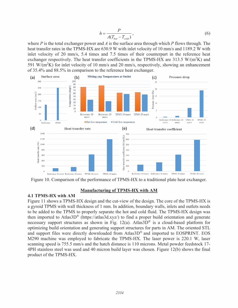
To show the efficiency of the TPMS-HX, the TPMS-HX is benchmarked against a traditional plate heat exchanger with straight channels. The dimensions of the traditional heat exchanger are the same as the TPMS-HX. Two hot flow domains are sandwiched with two cold flow domains to resemble the flow condition in the TPMS-HX. Figure 10 show the comparison of those two type of heat exchanger at inlet velocity of 10 mm/s and 20 mm/s. The interfacial surface area between the cold and hot flow is 251.5 cm2 in TPMS-HX and 120 cm2 in the reference heat exchanger as shown in Fig. 10(a). At the outlet, the mixing-cup temperature is significantly different for those two types of heat exchangers as shown in Fig. 10(b). The hot and cold fluid temperatures in TPMS-HX are much closer, showing a difference of 4.5 °C for inlet velocity of 10 mm/s and 7.9 °C for inlet velocity of 20 mm/s, as opposed to a difference of 42.4 °C for inlet velocity of 10 mm/s and 52.5 °C for inlet velocity of 20 mm/s in the reference heat exchanger. This is due the high heat transfer rate in TPMS-HX. Figure 10(c) shows the maximum pressure drop. The pressure drop in TPMS-HX is also much higher than that in the reference heat exchanger. Maximum pressure drop in TPMS-HX with inlet velocity of 20 mm/s is 19.15 Pa while the counterpart in the reference heat exchanger is only 1 Pa. Figure 10(d) and 10(e) shows the comparison of heat transfer rate and heat transfer coefficients. Heat transfer coefficients are calculated as
2333
x= 0 x=30mm x= 60mm degC - - - - 100
90
80
70
60
50
x=20mm x = 50 mm x = 100 mm
40
30
20
( )hot cold
PhA T T
, (6)
where P is the total exchanger power and A is the surface area through which P flows through. The heat transfer rates in the TPMS-HX are 630.9 W with inlet velocity of 10 mm/s and 1189.2 W with inlet velocity of 20 mm/s, 5.4 times and 7.5 times of their counterpart in the reference heat exchanger respectively. The heat transfer coefficients in the TPMS-HX are 313.5 W/(m2K) and 591 W/(m2K) for inlet velocity of 10 mm/s and 20 mm/s, respectively, showing an enhancement of 35.4% and 88.5% in comparison to the reference heat exchanger.
Figure 10. Comparison of the performance of TPMS-HX to a traditional plate heat exchanger.
Manufacturing of TPMS-HX with AM4.1 TPMS-HX with AMFigure 11 shows a TPMS-HX design and the cut-view of the design. The core of the TPMS-HX is a gyroid TPMS with wall thickness of 1 mm. In addition, boundary walls, inlets and outlets needs to be added to the TPMS to properly separate the hot and cold fluid. The TPMS-HX design was then imported to Atlas3D® (https://atlas3d.xyz/) to find a proper build orientation and generate necessary support structures as shown in Fig. 12(a). Atlas3D® is a cloud-based platform for optimizing build orientation and generating support structures for parts in AM. The oriented STL and support files were directly downloaded from Atlas3D® and imported to EOSPRINT. EOS M290 machine was employed to fabricate the TPMS-HX. The laser power is 220.1 W, laser scanning speed is 755.5 mm/s and the hatch distance is 110 microns. Metal powder feedstock 17-4PH stainless steel was used and 40 micron build layer was chosen. Figure 12(b) shows the final product of the TPMS-HX.
2334
(a) Surface area
300
250
~ 200 ~
"' ~ 150 ., u
I ,5 !3 100 r/l
50
0 Reference TPMS
(d) 1400
1200
§: 1000
E ~
800 ~
~ 600 b
~ 400
200
0 -
(b) Mixing-cup Temperature at Outlet (c) Pressure drop 100 25 90
C 80 ~ 70
"" 60 !: = 50
t 40 Q, 30 a i: 20
10 0
20
I i
I ! 15
I I e
10
~ 0..
Reference 10 Reference 20 TPMS 10 mm/s TPMS 20 mm/s I mm/s mm/s
■ Hot flow temperature ■ Cold flow temperature
Heat transfer rate
• I
(e) 700
~ a 600
[ 500
.~ 400
!i3 8 300 u
~ 200
~ ~ 100
~
0 -Reference IO Reference 20 TPMS 10 1PMS 20 mm/s mm!s mm/s mm/s
Heat transfer coefficient
■ I I Reference 10 tnm's Reference 20 mm/s TPMS 10 mm/s TPMS 20 mmls Reference l 0 mm.ls Reference 20 mm/s TPMS l 0 nun/s TPMS20mm/s

Figure 11. (a) TPMS-HX design. (b) Cut-view of the TPMS-HX design.
Figure 12 (a) TPMS-HX and its support structures in Atlas3D viewer. (b) TPMS-HX printed with EOS M290 machine.
2335

4.2 Manufacturability of TPMS-HX by AM Figure 13 shows a TPMS-HX with periodic length of 10 mm and wall thickness of 0.2 mm
printed with a layer thickness of 40 microns in an EOS M290 machine. The TPMS-HX failed in leak test and after cutting the TPMS-HX with electrical discharge machining (EDM), a uniform distribution of voids on the TPMS can be observed. Those voids were probably due lack of fusion and were avoided by increasing the wall thickness to 1 mm in the new design. Influential factors on manufacturability of TPMSs include the types of triply periodic minimal surface, periodic length, wall thickness, build orientation and etc. The periodic length of the TPMS should be within a threshold so that heat at overhanging regions of TPMSs can dissipate efficiently. Small wall thickness is desired to reduce thermal resistance. However, strength and integrity of TPMSs also decreases with decreasing wall thickness.
Figure 13. A TPMS-HX failed on leaking test due to voids on the TPMS.
Conclusion In this study we proposed a novel heat exchanger design by utilizing the TPMS. The
performance of the heat exchanger was demonstrated by developing a CFD model in COMSOL. Simulation results showed that heat transfer rates were improved by a factor of 7.5 times in comparison to a traditional plate heat exchanger. Finally, an industrial-size TPMS-HX was printed with an EOS M290 DMLS machine and manufacturability study on the TPMS-HX showed that a wall thickness larger than 0.2 mm was desired.
References 1. Ohadi, M., et al., Recent Developments in High Temperature Heat Exchangers: A
Review. Frontiers in Heat and Mass Transfer, 2018. 11.2. Li, Q., et al., Compact heat exchangers: A review and future applications for a new
generation of high temperature solar receivers. Renewable and Sustainable EnergyReviews, 2011. 15(9): p. 4855-4875.
3. Southall, D., R.L. Pierres, and S.J. Dewson. Design Considerations for Compact HeatExchangers. in Proceedings of the 2008 International Congress on Advances in NuclearPower Plants 2008. Anaheim, CA USA.
4. Gibson, I., D.W. Rosen, and B. Stucker, Additive Manufacturing Technologies: RapidPrototyping to Direct Digital Manufacturing. 2009: Springer US.
2336

5. Gu, D.D., et al., Laser additive manufacturing of metallic components: materials,processes and mechanisms. International Materials Reviews, 2012. 57(3): p. 133-164.
6. Neugebauer, R., et al., Additive manufacturing boosts efficiency of heat transfercomponents. Assembly Automation, 2011. 31(4): p. 344-347.
7. Heat exchanger designed by EOShttps://www.eos.info/industries_markets/industry/other_industrial_applications.
8. Slaughter, V.B., Method of using triply periodic minimal surfaces and minimal skeletonsto make heat exchanger components 2006, Boeing Co: US.
9. Ryan, R.C., Triply periodic minimal surface area mass and heat transfer packing 2013,GEOSEPAA LLC US.
10. Nguyen, D.T., et al. Triply periodic triply periodic minimal surface heat exchangers forsupercritical CO2 cycles. in Greenhouse Gas Control Technologies Conference. 2018.Melbourne, Australia.
11. Chandrasekaran, G., 3D Printed Heat Exchangers An Experimental Study, in MechanicalEngineering. 2018, Arizona State University.
12. Michielsen, K. and J.S. Kole, Photonic band gaps in materials with triply periodicsurfaces and related tubular structures. Physical Review B, 2003. 68(11): p. 115107.
13. Strano, G., et al., A new approach to the design and optimisation of support structures inadditive manufacturing. The International Journal of Advanced ManufacturingTechnology, 2013. 66(9-12): p. 1247-1254.
2337