design of a broadband soft x-ray...
TRANSCRIPT

Design of a broadband soft x-raypolarimeter
Herman L. MarshallH. Moritz GüntherRalf K. HeilmannNorbert S. SchulzMark EganTim HellicksonSarah N. T. HeineDavid L. WindtEric M. GulliksonBrian RamseyGianpiero TagliaferriGiovanni Pareschi
Herman L. Marshall, H. Moritz Günther, Ralf K. Heilmann, Norbert S. Schulz, Mark Egan, Tim Hellickson,Sarah N. T. Heine, David L. Windt, Eric M. Gullikson, Brian Ramsey, Gianpiero Tagliaferri,Giovanni Pareschi, “Design of a broadband soft x-ray polarimeter,” J. Astron. Telesc. Instrum. Syst. 4(1),011005 (2018), doi: 10.1117/1.JATIS.4.1.011005.
Downloaded From: https://www.spiedigitallibrary.org/journals/Journal-of-Astronomical-Telescopes,-Instruments,-and-Systems on 4/25/2018 Terms of Use: https://www.spiedigitallibrary.org/terms-of-use

Design of a broadband soft x-ray polarimeter
Herman L. Marshall,a,* H. Moritz Günther,a Ralf K. Heilmann,a Norbert S. Schulz,a Mark Egan,aTim Hellickson,a,b Sarah N. T. Heine,a David L. Windt,c Eric M. Gullikson,d Brian Ramsey,eGianpiero Tagliaferri,f and Giovanni PareschifaMIT Kavli Institute, Cambridge, Massachusetts, United StatesbColorado University, Laboratory of Atmosphere and Space Physics, Boulder, Colorado, United StatescReflective X-ray Optics, New York, New York, United StatesdLawrence Berkeley National Laboratory, Berkeley, California, United StateseNASA Marshall Space Flight Center, Huntsville, Alabama, United StatesfIstituto Nazionale di Astrofisica, Osservatorio Astronomico di Brera, Milano, Italy
Abstract. We describe an optical design and possible implementation of a broadband soft x-ray polarimeter. Ourarrangement of gratings is designed optimally for the purpose of polarimetry with broadband focusing optics bymatching the dispersion of the spectrometer channels to laterally graded multilayers (LGMLs). The system canachieve polarization modulation factors over 90%. We implement this design using a single optical system bydividing the entrance aperture into six sectors; high efficiency, blazed gratings from opposite sectors are orientedto disperse to a common LGML forming three channels covering the wavelength range from 35 to 75 Å (165 to350 eV). The grating dispersions and LGML position angles for each channel are 120 deg to each other. CCDdetectors then measure the intensities of the dispersed spectra after reflection and polarizing by the LGMLs,giving the three Stokes parameters needed to determine a source’s linear polarization fraction and orientation.The design can be extended to higher energies as LGMLs are developed further. We describe examples of thepotential scientific return from instruments based on this design. © The Authors. Published by SPIE under a Creative Commons
Attribution 3.0 Unported License. Distribution or reproduction of this work in whole or in part requires full attribution of the original publication, including its
DOI. [DOI: 10.1117/1.JATIS.4.1.011005]
Keywords: x-ray; polarimeter; astronomy; multilayer; mirror; grating.
Paper 17097SSP received Nov. 23, 2017; accepted for publication Mar. 12, 2018; published online Apr. 6, 2018.
1 IntroductionOver 40 years, the x-ray polarization of only the crab nebula hasbeen measured to better than 3σ, as found using OSO-8.1,2 Overthe entire history of x-ray astronomy, there has never been amission or instrument flown that was designed to measurethe polarization of x-rays below 1 keV. We have developed adesign that should be able to measure x-ray polarization overa broad energy range of x-rays below 1 keV.
The value of x-ray polarimetry to the scientific communitywas underscored by NASA’s selection of the Imaging X-rayPolarimetry Explorer (IXPE3), in the most recent NASA SMEXcycle. IXPE uses photoelectron-tracking detectors with sensitiv-ity in the 2- to 8-keV band. Our design provides a broadbandcapability below 1 keV that is complementary to IXPE and otherinstruments operating at higher energies. Although fundamen-tally based on Bragg reflection, our design mitigates the intrinsi-cally narrow band nature of such reflectors. See Kaaret4 for ageneral discussion of polarimeters based on Bragg reflection(e.g., OSO-8), those based on photoelectron tracking (e.g.,IXPE), and those based on Compton scattering (e.g., PoGO+5).Some sources, such as many isolated neutron stars (NSs), arepredominantly observable only below 1 keV, where the effectsof vacuum birefringence can be observed. It is likely that thepolarization fraction or position angle vary with energy inmany astrophysical situations (see Sec. 5), addressable usingan instrument of our design in combination with IXPE. For
example, there could be a polarization angle swing of 90 degin AGN spectra near 2 keV due to return radiation.6
We have presented early designs in various proceedings,7–10
but in this paper, we provide a fundamental optical design devel-oped specifically for use in a soft x-ray polarimeter. In Sec. 2, wepresent the basic design, whereas Sec. 3 provides details of animplementation that can detect polarizations of various sourceseven in exposures of a few hundred seconds as are available in asounding rocket experiment (the rocket experiment demonstra-tion of a soft x-ray polarimeter, or the REDSoX Polarimeter).(The name of the instrument is used with the permission ofMajor League Baseball and the Red Sox Baseball Club.) Theimplementation is based on the demonstrated performancesof previously fabricated components and could be readilyadapted for an orbital mission. In Sec. 4, we present ray-tracingresults to validate the basic design and assess the fabrication andoperational tolerances. In Sec. 5, we describe observations thatcould be carried out with a sounding rocket experiment and thescientific return from an orbital version of the instrument.
2 Optical Design
2.1 Overview
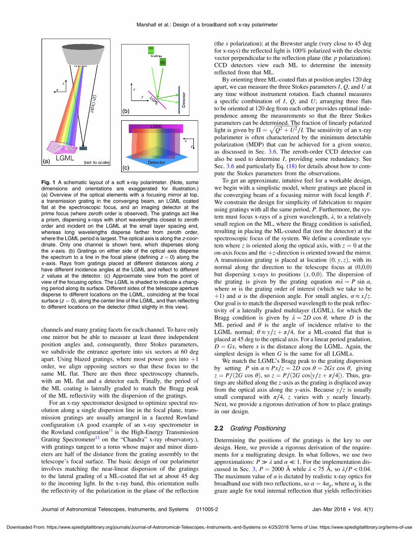
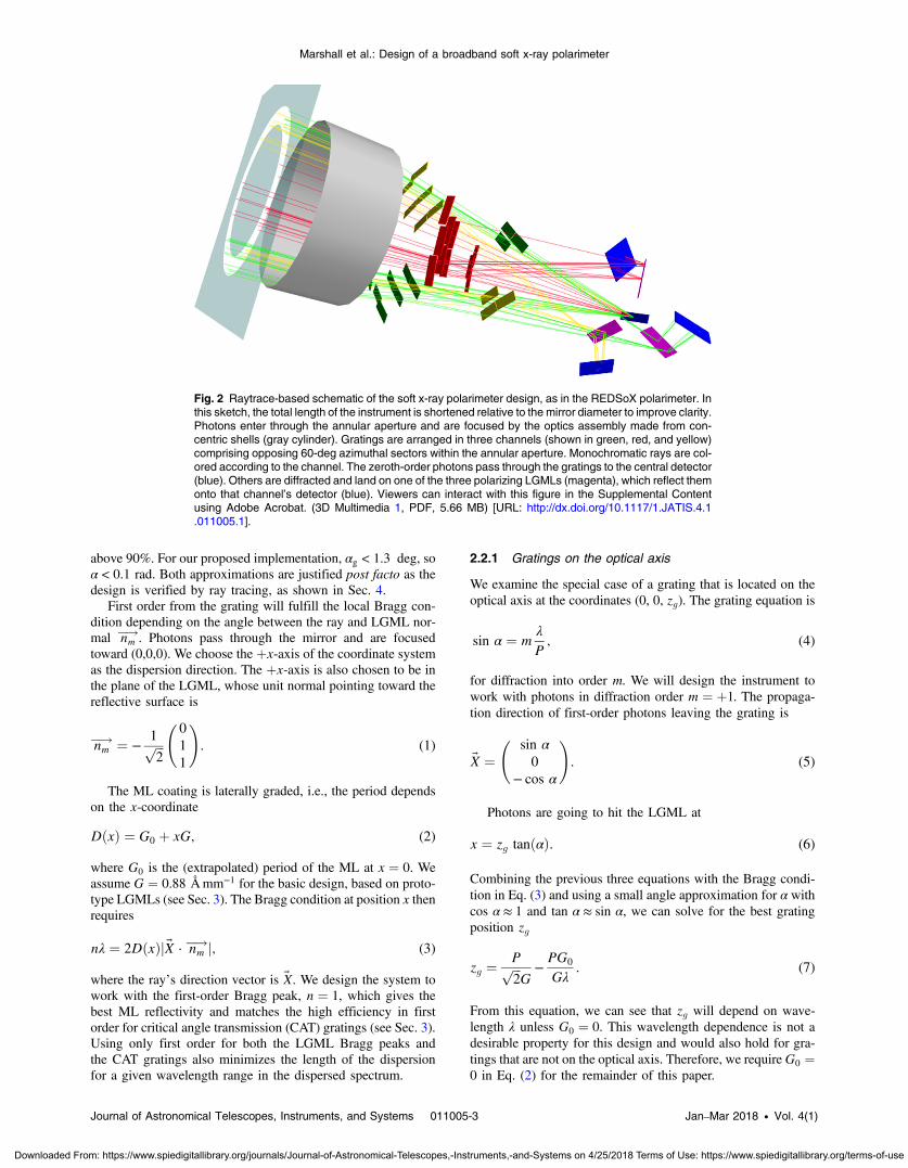
Our design starts with a dispersive x-ray spectrometer using gra-tings. Figure 1 shows a single-channel schematic design, withfocusing optical assembly (“mirror”), gratings placed at somelocation along the optical axis, a multilayer (ML)-coated flatat the focus of the spectrometer thus created, and a detectorfor the reflected spectra. Figure 2 shows a rendered three-dimen-sional (3-D) view of all optical elements, with three independent
*Address all correspondence to: Herman L. Marshall, E-mail: [email protected]
Journal of Astronomical Telescopes, Instruments, and Systems 011005-1 Jan–Mar 2018 • Vol. 4(1)
Journal of Astronomical Telescopes, Instruments, and Systems 4(1), 011005 (Jan–Mar 2018)
Downloaded From: https://www.spiedigitallibrary.org/journals/Journal-of-Astronomical-Telescopes,-Instruments,-and-Systems on 4/25/2018 Terms of Use: https://www.spiedigitallibrary.org/terms-of-use
channels and many grating facets for each channel. To have onlyone mirror but be able to measure at least three independentposition angles and, consequently, three Stokes parameters,we subdivide the entrance aperture into six sectors at 60 degapart. Using blazed gratings, where most power goes into þ1
order, we align opposing sectors so that these focus to thesame ML flat. There are then three spectroscopy channels,with an ML flat and a detector each. Finally, the period ofthe ML coating is laterally graded to match the Bragg peakof the ML reflectivity with the dispersion of the gratings.
For an x-ray spectrometer designed to optimize spectral res-olution along a single dispersion line in the focal plane, trans-mission gratings are usually arranged in a faceted Rowlandconfiguration (A good example of an x-ray spectrometer inthe Rowland configuration11 is the High-Energy TransmissionGrating Spectrometer12 on the “Chandra” x-ray observatory.),with gratings tangent to a torus whose major and minor diam-eters are half of the distance from the grating assembly to thetelescope’s focal surface. The basic design of our polarimeterinvolves matching the near-linear dispersion of the gratingsto the lateral grading of a ML-coated flat set at about 45 degto the incoming light. In the x-ray band, this orientation nullsthe reflectivity of the polarization in the plane of the reflection
(the s polarization); at the Brewster angle (very close to 45 degfor x-rays) the reflected light is 100% polarized with the electricvector perpendicular to the reflection plane (the p polarization).CCD detectors view each ML to determine the intensityreflected from that ML.
By orienting three ML-coated flats at position angles 120 degapart, we can measure the three Stokes parameters I,Q, andU atany time without instrument rotation. Each channel measuresa specific combination of I, Q, and U; arranging three flatsto be oriented at 120 deg from each other provides optimal inde-pendence among the measurements so that the three Stokesparameters can be determined. The fraction of linearly polarizedlight is given by Π ¼
ffiffiffiffiffiffiffiffiffiffiffiffiffiffiffiffiffiffiQ2 þU2
p∕I. The sensitivity of an x-ray
polarimeter is often characterized by the minimum detectablepolarization (MDP) that can be achieved for a given source,as discussed in Sec. 3.6. The zeroth-order CCD detector canalso be used to determine I, providing some redundancy. SeeSec. 3.6 and particularly Eq. (18) for details about how to com-pute the Stokes parameters from the observations.
To get an approximate, intuitive feel for a workable design,we begin with a simplistic model, where gratings are placed inthe converging beam of a focusing mirror with focal length F.We constrain the design for simplicity of fabrication to requireusing gratings with all the same period, P. Furthermore, the sys-tem must focus x-rays of a given wavelength, λ, to a relativelysmall region on the ML, where the Bragg condition is satisfied,resulting in placing the ML-coated flat (not the detector) at thespectroscopic focus of the system. We define a coordinate sys-tem where z is oriented along the optical axis, with z ¼ 0 at theon-axis focus and theþz-direction is oriented toward the mirror.A transmission grating is placed at location ð0; y; zÞ, with itsnormal along the direction to the telescope focus at (0,0,0)but dispersing x-rays to positions ðx; 0;0Þ. The dispersion ofthe grating is given by the grating equation mλ ¼ P sin α,where m is the grating order of interest (which we take to beþ1) and α is the dispersion angle. For small angles, α ≈ x∕z.Our goal is to match the dispersed wavelength to the peak reflec-tivity of a laterally graded multilayer (LGML), for which theBragg condition is given by λ ¼ 2D cos θ, where D is theML period and θ is the angle of incidence relative to theLGML normal; θ ≈ y∕zþ π∕4, for a ML-coated flat that isplaced at 45 deg to the optical axis. For a linear period gradation,D ¼ Gx, where x is the distance along the LGML. Again, thesimplest design is when G is the same for all LGMLs.
We match the LGML’s Bragg peak to the grating dispersionby setting P sin α ≈ Px∕z ¼ 2D cos θ ¼ 2Gx cos θ, givingz ¼ P∕ð2G cos θÞ, so z ¼ P∕ð2G cos½y∕zþ π∕4�Þ. Thus, gra-tings are shifted along the z-axis as the grating is displaced awayfrom the optical axis along the y-axis. Because y∕z is usuallysmall compared with π∕4, z varies with y nearly linearly.Next, we provide a rigorous derivation of how to place gratingsin our design.
2.2 Grating Positioning
Determining the positions of the gratings is the key to ourdesign. Here, we provide a rigorous derivation of the require-ments for a multigrating design. In what follows, we use twoapproximations: P ≫ λ and α ≪ 1. For the implementation dis-cussed in Sec. 3, P ¼ 2000 Å while λ < 75 Å, so λ∕P < 0.04.The maximum value of α is dictated by realistic x-ray optics forbroadband use with two reflections, so α ¼ 4αg, where αg is thegraze angle for total internal reflection that yields reflectivities
Fig. 1 A schematic layout of a soft x-ray polarimeter. (Note, somedimensions and orientations are exaggerated for illustration.)(a) Overview of the optical elements with a focusing mirror at top,a transmission grating in the converging beam, an LGML coatedflat at the spectroscopic focus, and an imaging detector at theprime focus (where zeroth order is observed). The gratings act likea prism, dispersing x-rays with short wavelengths closest to zerothorder and incident on the LGML at the small layer spacing end,whereas long wavelengths disperse farther from zeroth order,where the LGML period is largest. The optical axis is along the z-coor-dinate. Only one channel is shown here, which disperses alongthe x -axis. (b) Gratings on either side of the optical axis dispersethe spectrum to a line in the focal plane (defining z ¼ 0) along thex -axis. Rays from gratings placed at different distances along zhave different incidence angles at the LGML and reflect to differentz values at the detector. (c) Approximate view from the point ofview of the focusing optics. The LGML is shaded to indicate a chang-ing period along its surface. Different sides of the telescope aperturedisperse to different locations on the LGML, coinciding at the focalsurface (z ¼ 0), along the center line of the LGML, and then reflectingto different locations on the detector (tilted slightly in this view).
Journal of Astronomical Telescopes, Instruments, and Systems 011005-2 Jan–Mar 2018 • Vol. 4(1)
Marshall et al.: Design of a broadband soft x-ray polarimeter
Downloaded From: https://www.spiedigitallibrary.org/journals/Journal-of-Astronomical-Telescopes,-Instruments,-and-Systems on 4/25/2018 Terms of Use: https://www.spiedigitallibrary.org/terms-of-use
above 90%. For our proposed implementation, αg < 1.3 deg, soα < 0.1 rad. Both approximations are justified post facto as thedesign is verified by ray tracing, as shown in Sec. 4.
First order from the grating will fulfill the local Bragg con-dition depending on the angle between the ray and LGML nor-mal nm
�!. Photons pass through the mirror and are focusedtoward (0,0,0). We choose the þx-axis of the coordinate systemas the dispersion direction. The þx-axis is also chosen to be inthe plane of the LGML, whose unit normal pointing toward thereflective surface is
EQ-TARGET;temp:intralink-;e001;63;320 nm�! ¼ −
1ffiffiffi2
p 0
1
1
!: (1)
The ML coating is laterally graded, i.e., the period dependson the x-coordinate
EQ-TARGET;temp:intralink-;e002;63;247DðxÞ ¼ G0 þ xG; (2)
where G0 is the (extrapolated) period of the ML at x ¼ 0. Weassume G ¼ 0.88 Åmm−1 for the basic design, based on proto-type LGMLs (see Sec. 3). The Bragg condition at position x thenrequires
EQ-TARGET;temp:intralink-;e003;63;172nλ ¼ 2DðxÞj~X · nm�!j; (3)
where the ray’s direction vector is ~X. We design the system towork with the first-order Bragg peak, n ¼ 1, which gives thebest ML reflectivity and matches the high efficiency in firstorder for critical angle transmission (CAT) gratings (see Sec. 3).Using only first order for both the LGML Bragg peaks andthe CAT gratings also minimizes the length of the dispersionfor a given wavelength range in the dispersed spectrum.
2.2.1 Gratings on the optical axis
We examine the special case of a grating that is located on theoptical axis at the coordinates (0, 0, zg). The grating equation is
EQ-TARGET;temp:intralink-;e004;326;390 sin α ¼ mλ
P; (4)
for diffraction into order m. We will design the instrument towork with photons in diffraction order m ¼ þ1. The propaga-tion direction of first-order photons leaving the grating is
EQ-TARGET;temp:intralink-;e005;326;316
~X ¼
sin α0
− cos α
!: (5)
Photons are going to hit the LGML at
EQ-TARGET;temp:intralink-;e006;326;250x ¼ zg tanðαÞ: (6)
Combining the previous three equations with the Bragg condi-tion in Eq. (3) and using a small angle approximation for α withcos α ≈ 1 and tan α ≈ sin α, we can solve for the best gratingposition zg
EQ-TARGET;temp:intralink-;e007;326;174zg ¼Pffiffiffi2
pG−PG0
Gλ: (7)
From this equation, we can see that zg will depend on wave-length λ unless G0 ¼ 0. This wavelength dependence is not adesirable property for this design and would also hold for gra-tings that are not on the optical axis. Therefore, we requireG0 ¼0 in Eq. (2) for the remainder of this paper.
Fig. 2 Raytrace-based schematic of the soft x-ray polarimeter design, as in the REDSoX polarimeter. Inthis sketch, the total length of the instrument is shortened relative to the mirror diameter to improve clarity.Photons enter through the annular aperture and are focused by the optics assembly made from con-centric shells (gray cylinder). Gratings are arranged in three channels (shown in green, red, and yellow)comprising opposing 60-deg azimuthal sectors within the annular aperture. Monochromatic rays are col-ored according to the channel. The zeroth-order photons pass through the gratings to the central detector(blue). Others are diffracted and land on one of the three polarizing LGMLs (magenta), which reflect themonto that channel’s detector (blue). Viewers can interact with this figure in the Supplemental Contentusing Adobe Acrobat. (3D Multimedia 1, PDF, 5.66 MB) [URL: http://dx.doi.org/10.1117/1.JATIS.4.1.011005.1].
Journal of Astronomical Telescopes, Instruments, and Systems 011005-3 Jan–Mar 2018 • Vol. 4(1)
Marshall et al.: Design of a broadband soft x-ray polarimeter
Downloaded From: https://www.spiedigitallibrary.org/journals/Journal-of-Astronomical-Telescopes,-Instruments,-and-Systems on 4/25/2018 Terms of Use: https://www.spiedigitallibrary.org/terms-of-use

2.2.2 General grating positioning
We now introduce a spherical coordinate system as shown inFig. 3. The polar angle (γg) is measured with respect to thex-axis and the yz-plane is the equatorial plane. This frame ismore convenient than the usual definition, where the polarangle is measured with respect to the z-axis because x is thedirection along which the period of the ML flat changes.Consider a grating located at
EQ-TARGET;temp:intralink-;e008;63;657 Xg�! ¼ rg
cos γgsin γg sin βgsin γg cos βg
!; (8)
where rg is the distance between the grating and the focal point(located at the origin of the coordinate system), γg is the polarangle, and βg is the azimuthal angle measured in the yz-planefrom the z-axis. These angles are shown in Fig. 3. A photonincident upon this grating will have the direction vector~X ¼ −ðsin γg; cos γg sin βg; cos γg cos βgÞ. We place the gra-tings so that they are essentially perpendicular to the incomingphotons (except for an adjustment for the blaze angle describedin Sec. 2.5) to reduce the shadows cast by the grating supportstructure (see Sec. 3). We also want to orient the gratings suchthat they disperse along the x-axis. We can then write the dif-fraction of photons as a rotation with angle α from Eq. (4)around the axis ~A
EQ-TARGET;temp:intralink-;e009;63;459
~A ¼ Xg�!
×
1
0
0
!¼ 0
sin γg cos βg− sin γg sin βg
!: (9)
We can write the rotation matrix around this axis as
EQ-TARGET;temp:intralink-;e010;326;741
R ¼ cos αE
þ sin α
0B@
0 sin γg sin βg sin γg cos βg
− sin γg sin βg 0 0
− sin γg cos βg 0 0
1CA
þ ð1− cos αÞ
0B@
0 0 0
0 : : : : : :
0 : : : : : :
1CA; (10)
where E is the identity matrix and we use the approximationcosðαgÞ ≈ 1. The direction vector X1
�!of a dispersed first-
order photon is
EQ-TARGET;temp:intralink-;e011;326;581
X1
�! ¼ R~X
¼ −
0B@
sin γg
cos γg sin βg
cos γg cos βg
1CA −
λ
P
0B@
cos2 γg
− sin γg cos γg sin βg
− sin γg cos γg cos βg
1CA;
(11)
where we have used Eq. (4).We can now plug this photon direction vector into the Bragg
condition, Eq. (3), use Eq. (2), and set G0 ¼ 0 to obtain
EQ-TARGET;temp:intralink-;e012;326;447λ ¼ffiffiffi2
pGx cos γgðsin βg þ cos βgÞ
�1 −
λ
Psin γg
�; (12)
where the last term can be dropped because the wavelength λ ismuch smaller than the grating constant P in our implementation.
We need to express the position x in terms of the gratingcoordinates and the photon wavelength λ. The equation fora diffracted ray is
EQ-TARGET;temp:intralink-;e013;326;347
~X 0 ¼ Xg�!þ c X1
�!; (13)
for some value of c. It is sufficient to just write out the z-com-ponent of this equation to see where the ray intersects theLGML, which will happen when the ray passes the planez ¼ 0. Solving for c gives
EQ-TARGET;temp:intralink-;e014;326;268c ¼ rgP
P − λ sin γg≈ rg; (14)
and substituting this result into the x-component of Eq. (13)yields
EQ-TARGET;temp:intralink-;e015;326;201x ¼ rgPλ sin2 γg: (15)
Last, we obtain rg for a grating for any given γg, βg by insertingEq. (15) into Eq. (12)
EQ-TARGET;temp:intralink-;e016;326;140rg ¼Pffiffiffi
2p
G sin3 γgðsin βg þ cos βgÞ: (16)
With Eq. (16), we then have the position of the grating usingEq. (8) given values of γg and βg.
Fig. 3 Sketch of the geometry, showing three polarimetry channeldetectors (blue), one direct imaging detector (blue rectangle at thecoordinate system origin), three ML flats (magenta rectangles), andthree gratings (red rectangles). The distance r g (orange vector) isfrom the origin to the center of the grating marked by the graypoint. The angle γg , indicated by the blue wedge, is the angle tothe grating from the x -axis. The angle βg , indicated by the darkgray wedge, is the angle between the z-axis and the projection ofthe line to the grating center onto the yz-plane.
Journal of Astronomical Telescopes, Instruments, and Systems 011005-4 Jan–Mar 2018 • Vol. 4(1)
Marshall et al.: Design of a broadband soft x-ray polarimeter
Downloaded From: https://www.spiedigitallibrary.org/journals/Journal-of-Astronomical-Telescopes,-Instruments,-and-Systems on 4/25/2018 Terms of Use: https://www.spiedigitallibrary.org/terms-of-use

2.3 Filling the Space Available With Gratings
Equation 16 specifies where a grating must be positioned fora given ðγg; βgÞ to direct photons with m ¼ þ1 to the LGMLso that the Bragg condition is satisfied. The transmission gra-tings planned for our implementation of the design have finitesize and should be placed normal to the incoming (converging)photons. For these reasons, the gratings cannot follow the shapeof the surface given by Eq. (16) exactly but can be approximatedsufficiently. In our implementation, we place gratings in a rec-tangular grid to fill the annulus under the mirror shells that istraversed by the photons after focusing. We apply Eq. (16) tothe center of each grating and use ray-tracing to calculate thenonideal effects arising from the finite size of flat gratings.
The result for our sounding rocket implementation can be seenin Sec. 3.2.
2.4 Multiple Channels
As described in Secs. 1 and 2.1, the REDSoX polarimeter con-sists of three LGMLs and corresponding detectors that measurepolarization independently. To achieve this, the rectangular gridof gratings does not cover the full annulus but only two oppos-ing sectors, each of which is 60-deg wide. An opposing pair ofsector images onto one of the LGMLs; the combination of gra-tings, LGML, and detector comprises a “channel.” One of thetwo segments in each channel is “high” [larger rg because β > 0,see Eq. (16)], and the other one is “low” (smaller rg becauseβ < 0).
There are three channels. For channels 2 and 3, all gratingsand the corresponding LGML and CCD detector are rotated by120 deg and −120 deg, respectively, around the optical axiswith respect to channel 1. See Figs. 2, 8, and 13.
2.5 Grating Blaze Angle
The grating placement as discussed above is for transmissiongratings with similar efficiencies in positive and negative dif-fraction orders. To reduce mass and cost, we plan to use gratingsin which the diffraction efficiency is maximized to one side byblazing (tilting) the grating surface. To take advantage of theblaze feature, every grating is rotated by θB around the gratingbar axis, which we will define as its pitch (Fig. 4). Generally, θBis small enough that there is no significant shadowing by thegrating support structure.
3 ImplementationOur optical schematic has been proposed to NASA for imple-mentation in a sounding rocket configuration. This implemen-tation was dubbed the rocket experiment demonstration of a softx-ray polarimeter or the REDSoX polarimeter. The main con-straints on a sounding rocket payload are the maximum diameterof the optics assembly, about 0.45 m, and the total length of theinstrument, limiting the mirror’s focal length to 2.5 m. Exposure
Fig. 4 Sketch of a critical angle transmission (CAT) grating. The solidblue line is the path of the incoming photon. The red line isperpendicular to the incoming photon and would be the plane of atraditional transmission grating (gray grating bars). Instead, theCAT grating is blazed by the angleΘB , which makes photons “bounceoff” the walls of the grating bars (thick black lines) and all the dis-persed signal ends up toward the right of the zeroth order. Instead,the blaze angle was −ΘB , photons would “bounce off” the otherside of the grating bars and would be blazed toward a location tothe left of the zeroth order. Note that for the blaze angle ΘB theangle between the incoming ray (solid blue line) and the diffractedray (dashed blue line) is 2ΘB . Sometimes this 2ΘB angle is called“blaze angle” in the literature, which can lead to confusion.
Fig. 5 Cutaway rendering of the REDSoX polarimeter from an engineering design, showing the mirror,gratings (in gold), the optical bench, the focal plane baffle (with three slits for dispersed events) over thependulum valve for the detector chamber, and the back of the detector chamber with the electronics box.The top and bottom grating groups intercept opposite 60-deg sectors of focused x-rays, dispersing themthrough the baffle slit to the left of the central (rectangular) aperture for zeroth order. See Fig. 13 for arendering of the interior of the detector chamber. For clarity, only a few mirror shells and grating groupsare rendered.
Journal of Astronomical Telescopes, Instruments, and Systems 011005-5 Jan–Mar 2018 • Vol. 4(1)
Marshall et al.: Design of a broadband soft x-ray polarimeter
Downloaded From: https://www.spiedigitallibrary.org/journals/Journal-of-Astronomical-Telescopes,-Instruments,-and-Systems on 4/25/2018 Terms of Use: https://www.spiedigitallibrary.org/terms-of-use

time is limited by the total mass of the payload, which includesthe attitude system. For the REDSoX polarimeter, this exposuretime is about 300 s. We now describe the components of theREDSoX polarimeter as currently designed; more details canbe found elsewhere.13 Figure 5 shows a rendering of ourimplementation.
3.1 Focusing Optics
The broadband focusing mirror should work well in the energyrange appropriate to the available MLs that can be used in the0.1- to 1.0-keV range. Type I Wolter designs are effective here,so we define the inner and outer radii as rI and rO. The tele-scope’s f-ratio should not be very small; the sounding rocketconstraints provide an f-ratio over 5, which suffices. Therequirement on the mirror half-power diameter (HPD) will bedetermined by setting a limit on the spectrometer’s spectral res-olution, which is derived from the gradient, G, of the laterallygraded ML (see Sec. 3.3). We anticipate that HPDs of <30 00 willbe sufficient and have been demonstrated by researchers at theBrera Observatory14,15 and at the Marshall Space FlightCenter.16 Five mandrels were made for the Micro-X project17
with a 2500-mm focal length, so we adopt this focal length.The focal plane scale is 82 00∕mm.
For the REDSoX polarimeter, there would be nine shells,with inner radii ranging from 14.96 to 20.22 cm and outerradii ranging from 16.94 to 22.88 cm. The mirror geometricarea is about 640 cm2, and we assume that the support structureblocks 12% of this area and then use reflectivity given by tworeflections from Ni-coated surfaces using the known grazeangles. The total mass of the mirror is expected to be about78 kg.
3.2 Gratings
For gratings, we baseline critical angle transmission (CAT)gratings18 developed in the Space Nanotechnology Lab (SNL)at MIT. These can now be reliably produced in a 10 × 30 mm(and a 30 × 30) format with period P ¼ 2000 Å on 0.5-mm-thick Si wafer substrates.19,20 We extrapolated measurementstaken at the advanced light source (ALS) to 70 Å using an effi-ciency model and then accounted for structural obscuration togenerate an efficiency model for our baseline effective area.We further note that the measured efficiencies in the 30- to70-Å range are generally closer to the models than the measure-ments below 30 Å.21
A grating in a holder is shown schematically in Fig. 6 andseveral gratings are assembled stair-stepped into one “sector” asshown in Fig. 7. The sectors are mounted approximately azimu-thally about the optical axis, as shown in Fig. 8, so that thedispersion direction is along the long dimension. The gratingsare mounted in a blazed configuration, rotated so that x-raysreflect off of the polished grating sidewalls, increasing the effi-ciency in (what we define as) positive orders. The blaze condi-tion is described in Sec. 2.5 and shown in Fig. 4. The systemMDP (from Sec. 3.6) varies inversely with the square root of thegrating efficiency, so we computed the MDP as a function of
Fig. 6 Engineering drawing of a CAT grating in a holder. The L2 sup-port structure is visible as the hexagonal structure that is 0.5-mmdeep; the grating is a 4-μm layer on top, with the dispersion alongthe long axis.
Fig. 7 Engineering design of an assembly of gratings for one (high)sector of the REDSoX polarimeter. The gratings are aligned to dis-perse either to the left or to the right, depending on whether theassembly is high or low along the optical axis. The gratings arestair-stepped so that the Bragg condition is met at the ML. Ribshave pins to securely position gratings below the Invar mounts andflexible arms above to maintain location.
Fig. 8 Grating assemblies as installed on the optical bench of theREDSoX polarimeter.
Journal of Astronomical Telescopes, Instruments, and Systems 011005-6 Jan–Mar 2018 • Vol. 4(1)
Marshall et al.: Design of a broadband soft x-ray polarimeter
Downloaded From: https://www.spiedigitallibrary.org/journals/Journal-of-Astronomical-Telescopes,-Instruments,-and-Systems on 4/25/2018 Terms of Use: https://www.spiedigitallibrary.org/terms-of-use

blaze angle, finding a minimum at about 0.8 deg (see Fig. 9).To increase the efficiency for dispersed x-rays, the throughput inthe zeroth order is decreased, as shown in Fig. 9.
3.3 Laterally Graded Multilayer Coatings
Under NASA funding, there is demonstrated performance ofLGMLs coated flats. An image of such an LGML is shownin Fig. 10. LGMLs have been made by reflective x-ray optics(RXO) and the center for x-ray optics (CXRO) that are suitablefor our design. The coating substrates are portions of highly pol-ished Si wafers, about 0.5-mm thick. They have linear periodspacing gradients of 0.88 Å∕mm to reflect and polarize x-rays from 17 to 75 Å (165 to 730 eV). The coating materialpairs were W∕B4C, C/CrCo, Cr∕B4C∕Sc, and La∕B4C.Reflection efficiencies at 45 deg were measured at the ALSin Berkeley, California, at 1- or 2-mm spacing for eachLGML.9,10 Results of these tests are shown in Fig. 11 for the
wavelength range of interest. Across each LGML, the Braggpeak deviates from linearity by <1%, ×2 smaller than theFWHM of the peak (Fig. 12).
The reflectivities of the LGMLs are critical to the perfor-mance of this design. The baseline implementation selectsthe 35 to 75 Å wavelength range due to the extents of theCCD detectors and the spectrometer dispersion relation.Referring to Fig. 11, the Cr/Sc LGML has the best reflectivityin the 35 to 50 Å range, C/CrCo is best in the 40 to 67 Å range,and La∕B4C is best longward of 67 Å. The flight LGML will bea mosaic of the three types, cut precisely at positions corre-sponding to Bragg peaks at 50 and/or 67 Å depending onthe LGML and mounted as an assembly for flight. The LGMLassemblies will be the same for each channel. When correctedfor the ALS beam polarization, the average reflectivity to un-polarized light is about 10%.
Fig. 10 A LGML coated flat fromRXO in a lab holder. It is about 0.5-mmthick and 47-mm long. The ML period, d , increases from left to right.
Fig. 11 Reflectivity measurements of LGMLs9,10 using a partiallypolarized beam at the ALS in Berkeley. The reflectivities weresampled at 1-mm spacing, starting below 30 Å (about 0.4 keV) forthe Cr/Sc sample (green) and at 2-mm spacing for the C/CoCr(red) and La∕B4C (violet) samples.
(a) (b)
Fig. 9 For the example of Mk 421, this shows the calculation of (a) theMDP and (b) zeroth-order count rate as a function of the CAT gratingblaze angle in the REDSoX polarimeter implementation. At 0.8 deg,the MDP is optimized at the expense of the count rate in the zerothorder. The MDP is insensitive to the blaze angle within 0.15 deg of theoptimum, setting the mounting angle tolerance.
10 20 30 40 50
Substrate position, X [mm]
20
30
40
50
60
70
CW
HM
wav
elen
gth,
lam
bda
[Å]
Fig. 12 Bragg peak wavelength as a function of position alonga LGML (A13164), made from alternating layers of C and a CoCralloy. The centroid of the Bragg peak is linear with position alongthe LGML to better than 1%, sufficient for an instrument, such asthe REDSoX polarimeter.
Journal of Astronomical Telescopes, Instruments, and Systems 011005-7 Jan–Mar 2018 • Vol. 4(1)
Marshall et al.: Design of a broadband soft x-ray polarimeter
Downloaded From: https://www.spiedigitallibrary.org/journals/Journal-of-Astronomical-Telescopes,-Instruments,-and-Systems on 4/25/2018 Terms of Use: https://www.spiedigitallibrary.org/terms-of-use

3.4 Detectors
The focal plane layout is shown in Fig. 13. For the CCD detec-tors, we use commercially available CCD cameras from XCAM.The CCDs are semicustom devices manufactured by e2v tech-nologies. These CCDs have typical quantum efficiencies of 80%to 90% in the energy range of 150 to 500 eV. Each CCD hasa 26.11- × 25.73-mm image area with 1632 horizontal and1608 vertical active pixels and full frame readout. The smallpixel size of 16 μm × 16 μm allows high-resolution imaging,but we can sum rows for fast readouts. Used with the spectrom-eter dispersion along the diagonal, the useful dispersion range isabout 35 mm, giving a 35 to 75 Å (165 to 350 eV) bandpass.
3.5 Background
To estimate the particle background, we use results from theSuzaku satellite in low Earth orbit. For the REDSoX polarim-eter, launching either from White Sands, Minnesota, or fromAustralia, the maximum altitude will be somewhat lower thanSuzaku, so the Suzaku background will be taken as an upperlimit. The particle background in the Suzaku backside-illuminatedCCD was 5 × 10⁻⁸ cnt∕s∕keV∕pixel or 1.5 × 10⁻⁵ cnt∕s∕mm2
in a 0.2-keV band at 0.3 keV.22 In the cross-dispersion direction,the dispersed spectral extraction region will be about twicethe size of the optics HPD, about 60″ or 0.7-mm wide. Inthe dispersion direction, the spectra are 35-mm long. Usingthree detectors and exposing for 300 s yields 0.3 countsexpected from particles. The x-ray background in the REDSoXpolarimeter bandpass is dominated by galactic emission, about10−3 cnt∕s∕ðarcminÞ2 in the ROSAT C band or 540 ph∕cm2∕s∕sr∕keV for ROSAT’s area (220 cm2) and bandwidth (0.1 keV).23
Thus, we expect about 30 cnt in 300 s across the REDSoX polar-imeter band in the solid angle of each detector. The LGMLs,however, have a bandpass of δE ¼ 0.025E, giving <2 countsexpected across the three detectors. Compared with a sourcewith 50 to 1000 counts, these backgrounds are negligible. To
avoid solar scattered background, we require that the anglebetween the telescope’s line of sight and the Sun should be>120 deg, as demonstrated by ROSAT.23
3.6 Baseline Performance
For a polarimeter, a figure of merit is the MDP at 99% confi-dence, given as a fraction MDP ¼ 4.29
ffiffiffiffiffiffiffiffiffiffiffiffiffiffiffiffiffiffiffiffiffiffiðRþ BÞ∕Tp∕ðμRÞ,
where R is the source count rate, B is the background countrate in a region that is the size of a typical image, T is the obser-vation time, and μ is the modulation factor of the signal relativeto the average signal for a source that is 100% polarized.4,24 Formost polarimeters operating in the 2- to 8-keV band, the mod-ulations factors peak at 0.5 to 0.7 [e.g., 3], whereas for theREDSoX polarimeter and other polarimeters based on Braggreflection, μ > 0.90. In Sec. 4, we verify that μ is this highfor the REDSoX polarimeter.
The effective area of the system was also validated usingray tracing developed for the REDSoX polarimeter project(see Sec. 4). The integrated area of the system, defined as A ¼∫AðλÞdλ is 185 cm2 Å. For a source with a flat spectrum,R ¼ IA, where I, one of the Stokes parameters, is the sourceflux in ph cm−2 s−1 Å−1. The zeroth-order detector also providesa measurement of I, with A0 ¼ 488 cm2 but with a less def-inite energy band due to the CCD spectral resolution.
Briefly, we describe how to measure the Stokes Q and Uparameters using just the polarimetry channel data, for the sim-ple case of a flat input spectrum. In flight, the system wouldmeasure count rates in each of three channels, denoted by Ri,for i ¼ 1: : : 3. For given values of I, Q, and U
EQ-TARGET;temp:intralink-;e017;326;425Ri ¼ AðI þ μQci þ μUsiÞ; (17)
where μ is averaged over the bandpass, ci ¼ cos 2θi,si ¼ − sin 2θi, and θi is the orientation of channel i’s LGMLwith respect to the coordinate system defining Q and U. Ifwe arrange the observation so that θ1 ¼ 0, then θ2 ¼ 2π∕3and θ3 ¼ 4π∕3 for three detectors at 120 deg to each other,and we can solve Eq. (17) for the Stokes parameters, obtainingEQ-TARGET;temp:intralink-;e018;326;328
I ¼ ðR1 þ R2 þ R3Þ∕ð3AÞQ ¼ ð2R1 − R2 − R3Þ∕ð3 μAÞU ¼ ðR2 − R3Þ∕ð31∕2 μAÞ: (18)
If θ1 ≠ 0, then an appropriate rotation by θ1 will properly orientQ and U on the sky. The linear polarization fraction isΠ ¼ ðQ2 þ U2Þ1∕2∕I, and the angle of the linear polarizationis ϕ ¼ arctan Q∕U. (The electric vector position angle, oftendenoted EVPA, is usually defined as the angle to the eastfrom north.) In practice, Eq. (17) will be somewhat more com-plicated by the dependence of I and μ on λ, so solving forQ andU will require a likelihood analysis of RiðλÞ and a forward-fold-ing methodology.25
4 Raytrace ValidationWe use the MARXS ray-trace code, which can handle polarizedx-rays.26 Details of the raytrace design and implementation areprovided elsewhere.27 Here, we give a general overview of thecomponents of the raytrace and how they have been used toverify the system performance and assess tolerances independ-ently of analytic methods. Figure 14 shows how rays passthrough the system.
Fig. 13 Interior of the detector vacuum chamber showing almost allfocal plane components: LGMLs, CCD faces, and flex prints (gold).A black anodized CCD baffle with a horizontal rectangular aperturerestricts the view of the CCDs to its LGML. The cylinder at thebase of the focal plane will be filled with liquid N2 prior to launch inthe sounding rocket implementation.
Journal of Astronomical Telescopes, Instruments, and Systems 011005-8 Jan–Mar 2018 • Vol. 4(1)
Marshall et al.: Design of a broadband soft x-ray polarimeter
Downloaded From: https://www.spiedigitallibrary.org/journals/Journal-of-Astronomical-Telescopes,-Instruments,-and-Systems on 4/25/2018 Terms of Use: https://www.spiedigitallibrary.org/terms-of-use
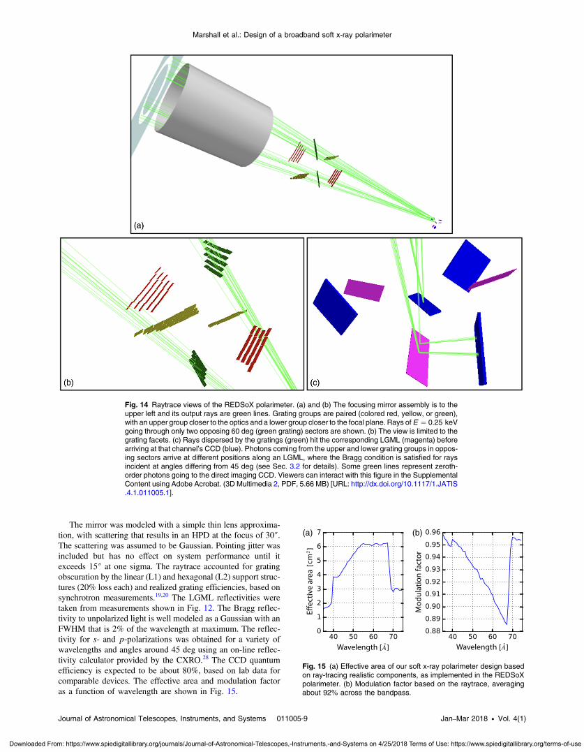
The mirror was modeled with a simple thin lens approxima-tion, with scattering that results in an HPD at the focus of 30″.The scattering was assumed to be Gaussian. Pointing jitter wasincluded but has no effect on system performance until itexceeds 15″ at one sigma. The raytrace accounted for gratingobscuration by the linear (L1) and hexagonal (L2) support struc-tures (20% loss each) and realized grating efficiencies, based onsynchrotron measurements.19,20 The LGML reflectivities weretaken from measurements shown in Fig. 12. The Bragg reflec-tivity to unpolarized light is well modeled as a Gaussian with anFWHM that is 2% of the wavelength at maximum. The reflec-tivity for s- and p-polarizations was obtained for a variety ofwavelengths and angles around 45 deg using an on-line reflec-tivity calculator provided by the CXRO.28 The CCD quantumefficiency is expected to be about 80%, based on lab data forcomparable devices. The effective area and modulation factoras a function of wavelength are shown in Fig. 15.
Fig. 14 Raytrace views of the REDSoX polarimeter. (a) and (b) The focusing mirror assembly is to theupper left and its output rays are green lines. Grating groups are paired (colored red, yellow, or green),with an upper group closer to the optics and a lower group closer to the focal plane. Rays of E ¼ 0.25 keVgoing through only two opposing 60 deg (green grating) sectors are shown. (b) The view is limited to thegrating facets. (c) Rays dispersed by the gratings (green) hit the corresponding LGML (magenta) beforearriving at that channel’s CCD (blue). Photons coming from the upper and lower grating groups in oppos-ing sectors arrive at different positions along an LGML, where the Bragg condition is satisfied for raysincident at angles differing from 45 deg (see Sec. 3.2 for details). Some green lines represent zeroth-order photons going to the direct imaging CCD. Viewers can interact with this figure in the SupplementalContent using Adobe Acrobat. (3D Multimedia 2, PDF, 5.66 MB) [URL: http://dx.doi.org/10.1117/1.JATIS.4.1.011005.1].
(a) (b)
Fig. 15 (a) Effective area of our soft x-ray polarimeter design basedon ray-tracing realistic components, as implemented in the REDSoXpolarimeter. (b) Modulation factor based on the raytrace, averagingabout 92% across the bandpass.
Journal of Astronomical Telescopes, Instruments, and Systems 011005-9 Jan–Mar 2018 • Vol. 4(1)
Marshall et al.: Design of a broadband soft x-ray polarimeter
Downloaded From: https://www.spiedigitallibrary.org/journals/Journal-of-Astronomical-Telescopes,-Instruments,-and-Systems on 4/25/2018 Terms of Use: https://www.spiedigitallibrary.org/terms-of-use
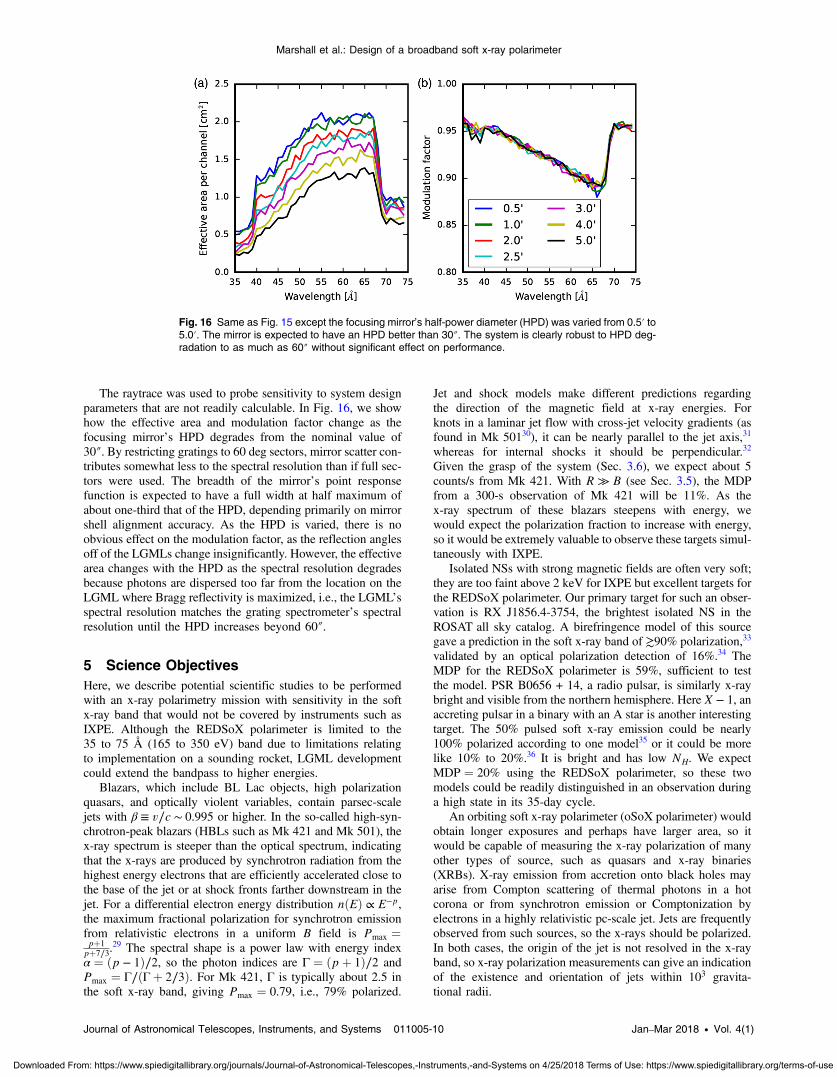
The raytrace was used to probe sensitivity to system designparameters that are not readily calculable. In Fig. 16, we showhow the effective area and modulation factor change as thefocusing mirror’s HPD degrades from the nominal value of30″. By restricting gratings to 60 deg sectors, mirror scatter con-tributes somewhat less to the spectral resolution than if full sec-tors were used. The breadth of the mirror’s point responsefunction is expected to have a full width at half maximum ofabout one-third that of the HPD, depending primarily on mirrorshell alignment accuracy. As the HPD is varied, there is noobvious effect on the modulation factor, as the reflection anglesoff of the LGMLs change insignificantly. However, the effectivearea changes with the HPD as the spectral resolution degradesbecause photons are dispersed too far from the location on theLGML where Bragg reflectivity is maximized, i.e., the LGML’sspectral resolution matches the grating spectrometer’s spectralresolution until the HPD increases beyond 60″.
5 Science ObjectivesHere, we describe potential scientific studies to be performedwith an x-ray polarimetry mission with sensitivity in the softx-ray band that would not be covered by instruments such asIXPE. Although the REDSoX polarimeter is limited to the35 to 75 Å (165 to 350 eV) band due to limitations relatingto implementation on a sounding rocket, LGML developmentcould extend the bandpass to higher energies.
Blazars, which include BL Lac objects, high polarizationquasars, and optically violent variables, contain parsec-scalejets with β ≡ v∕c ∼ 0.995 or higher. In the so-called high-syn-chrotron-peak blazars (HBLs such as Mk 421 and Mk 501), thex-ray spectrum is steeper than the optical spectrum, indicatingthat the x-rays are produced by synchrotron radiation from thehighest energy electrons that are efficiently accelerated close tothe base of the jet or at shock fronts farther downstream in thejet. For a differential electron energy distribution nðEÞ ∝ E−p,the maximum fractional polarization for synchrotron emissionfrom relativistic electrons in a uniform B field is Pmax ¼pþ1
pþ7∕3.29 The spectral shape is a power law with energy index
α ¼ ðp − 1Þ∕2, so the photon indices are Γ ¼ ðpþ 1Þ∕2 andPmax ¼ Γ∕ðΓþ 2∕3Þ. For Mk 421, Γ is typically about 2.5 inthe soft x-ray band, giving Pmax ¼ 0.79, i.e., 79% polarized.
Jet and shock models make different predictions regardingthe direction of the magnetic field at x-ray energies. Forknots in a laminar jet flow with cross-jet velocity gradients (asfound in Mk 50130), it can be nearly parallel to the jet axis,31
whereas for internal shocks it should be perpendicular.32
Given the grasp of the system (Sec. 3.6), we expect about 5counts/s from Mk 421. With R ≫ B (see Sec. 3.5), the MDPfrom a 300-s observation of Mk 421 will be 11%. As thex-ray spectrum of these blazars steepens with energy, wewould expect the polarization fraction to increase with energy,so it would be extremely valuable to observe these targets simul-taneously with IXPE.
Isolated NSs with strong magnetic fields are often very soft;they are too faint above 2 keV for IXPE but excellent targets forthe REDSoX polarimeter. Our primary target for such an obser-vation is RX J1856.4-3754, the brightest isolated NS in theROSAT all sky catalog. A birefringence model of this sourcegave a prediction in the soft x-ray band of ≳90% polarization,33
validated by an optical polarization detection of 16%.34 TheMDP for the REDSoX polarimeter is 59%, sufficient to testthe model. PSR B0656 + 14, a radio pulsar, is similarly x-raybright and visible from the northern hemisphere. Here X − 1, anaccreting pulsar in a binary with an A star is another interestingtarget. The 50% pulsed soft x-ray emission could be nearly100% polarized according to one model35 or it could be morelike 10% to 20%.36 It is bright and has low NH. We expectMDP ¼ 20% using the REDSoX polarimeter, so these twomodels could be readily distinguished in an observation duringa high state in its 35-day cycle.
An orbiting soft x-ray polarimeter (oSoX polarimeter) wouldobtain longer exposures and perhaps have larger area, so itwould be capable of measuring the x-ray polarization of manyother types of source, such as quasars and x-ray binaries(XRBs). X-ray emission from accretion onto black holes mayarise from Compton scattering of thermal photons in a hotcorona or from synchrotron emission or Comptonization byelectrons in a highly relativistic pc-scale jet. Jets are frequentlyobserved from such sources, so the x-rays should be polarized.In both cases, the origin of the jet is not resolved in the x-rayband, so x-ray polarization measurements can give an indicationof the existence and orientation of jets within 103 gravita-tional radii.
Fig. 16 Same as Fig. 15 except the focusing mirror’s half-power diameter (HPD) was varied from 0.5′ to5.0′. The mirror is expected to have an HPD better than 30″. The system is clearly robust to HPD deg-radation to as much as 60″ without significant effect on performance.
Journal of Astronomical Telescopes, Instruments, and Systems 011005-10 Jan–Mar 2018 • Vol. 4(1)
Marshall et al.: Design of a broadband soft x-ray polarimeter
Downloaded From: https://www.spiedigitallibrary.org/journals/Journal-of-Astronomical-Telescopes,-Instruments,-and-Systems on 4/25/2018 Terms of Use: https://www.spiedigitallibrary.org/terms-of-use

Transient XRBs with stellar-mass black holes like XTEJ1118 + 480 can be very soft and jets may contribute mostof the x-rays37—confirmable using polarimetry. A jet modelfor XTE J1118 indicates that the soft x-ray polarization shouldbe about 20%.38 The source was discovered with XTE anddetected by the extreme ultraviolet explorer at 100 eV, so thecolumn density is well below 1020 cm−2, making it a good targetfor the oSoX polarimeter. During its 2000 outburst, the flux den-sity at 0.3 keV was brighter than Mk 421,39 making it an excel-lent candidate for a target of opportunity observation.
Theoretical work indicates that AGN accretion disks and jetsshould be 10% to 20% polarized6,40 and that the polarizationangle and magnitude should change with energy in a waythat depends on the system inclination and the black holemass and spin. The variation of polarization with energycould be used as a probe of the black hole spin and the polari-zation position angle should rotate through 90 deg between 1and 2 keV.6 Thus, x-ray polarization measurements are neededboth above 2 keV (e.g., with IXPE) and below 1 keV with theoSoX polarimeter.
Finally, Sy 2 galaxies exhibit polarized broad lines in opticalspectra, an indication of scattering on a spatial scale much largerthan the opaque torus that obscures the nucleus.41 Similar scat-tering is expected in the x-ray spectrum below 1 keV, but thereare many emission lines from photoexcited gas that are likelyunpolarized.42 The oSoX polarimeter would obtain a spectrumwith sufficient resolution to separate lines and continuum todetect the scattered continuum or discern which lines originatecloser to the nucleus and are scattered like the optical broadlines.
6 SummaryWe have presented an arrangement of components that is spe-cifically designed for soft x-ray polarimetry. We have beendeveloping and testing potential components in the MIT polar-imetry lab.8–10,43 Although our proposed implementation is spe-cifically targeted for use in a sounding rocket flight, the designshould be readily adapted for orbital use. With exposure times ofdays to weeks, the MDP can easily be decreased to 1% or better,depending on the target. Many more types of sources may beobserved in an orbital mission—cataclysmic variables, activegalaxies, such as Seyfert 2 s, galactic black hole binaries, andpossibly γ-ray bursts.
If the readout detector length can be increased by addingdetectors, the bandpass and throughput of this design arethen limited predominantly by the dispersion of the gratingsand the efficiencies of the short-wavelength MLs. At higherdispersion, say with a longer focal length, the spectral resolutioncan be increased. For example, increasing the spectral resolutioncan be very useful for investigating the continuum betweenemission lines in Sy 2 galaxies.
We note also that the gratings are very thin and will passhigh-energy x-rays, say E > 3 keV. This feature allows us touse this design in combination with a focal plane polarimeterto provide a wider energy range.
AcknowledgmentsSupport for this work was provided by the National Aeronauticsand Space Administration through Grants NNX12AH12G andNNX17AE11G and by Research Investment Grants from theMIT Kavli Institute. The simulations make use of Astropy,a community-developed core Python package for astronomy.44
References1. R. Novick et al., “Detection of x-ray polarization of the crab nebula,”
Astrophys. J. 174, L1 (1972).2. M. C. Weisskopf et al., “A precision measurement of the x-ray polari-
zation of the crab nebula without pulsar contamination,” Astrophys. J.220, L117–L121 (1978).
3. M. C. Weisskopf et al., “The imaging x-ray polarimetry explorer(IXPE),” Proc. SPIE 9905, 990517 (2016).
4. P. Kaaret, “X-ray polarimetry,” arXiv:1408.5899 (2014).5. M. Chauvin et al., “Shedding new light on the crab with polarized
x-rays,” Sci. Rep. 7, 7816 (2017).6. J. D. Schnittman and J. H. Krolik, “X-ray polarization from accreting
black holes: the thermal state,” Astrophys. J. 701, 1175–1187 (2009).7. H. L. Marshall, “A soft x-ray polarimeter designed for broadband x-ray
telescopes,” Proc. SPIE 6688, 66880Z (2007).8. H. L. Marshall et al., “Progress toward a soft x-ray polarimeter,” Proc.
SPIE 8861, 88611D (2013).9. H. L. Marshall et al., “The use of laterally graded multilayer mirrors for
soft x-ray polarimetry,” Proc. SPIE 9144, 91441K (2014).10. H. L. Marshall et al., “The use of laterally graded multilayer mirrors for
soft x-ray polarimetry,” Proc. SPIE 9603, 960319 (2015).11. M. Born and E. Wolf, Principles of Optics Electromagnetic Theory of
Propagation, Interference and Diffraction of Light, Pergamon Press,Oxford, United Kingdom (1980).
12. C. R. Canizares et al., “The Chandra high-energy transmission grating:design, fabrication, ground calibration, and 5 years in flight,” Publ.Astron. Soc. Pac. 117, 1144–1171 (2005).
13. H. L. Marshall et al., “The rocket demonstration of a soft x-raypolarimeter (REDSoX polarimeter),” Proc. SPIE 10399, 103990K(2017).
14. O. Citterio et al., “Characteristics of the flight model optics for the JET-X telescope onboard the spectrum-x-gamma satellite,” Proc. SPIE 2805,56–65 (1996).
15. G. Pareschi et al., “Development of grazing-incidence multilayer mir-rors by direct Ni electroforming replication: a status report,” Proc. SPIE5900, 590008 (2005).
16. B. D. Ramsey et al., “The development of hard x-ray optics at MSFC,”Proc. SPIE 5168, 129–135 (2004).
17. E. Figueroa-Feliciano et al., “Update on the micro-X sounding rocketpayload,” Proc. SPIE 8443, 84431B (2012).
18. R. K. Heilmann et al., “Development of a critical-angle transmissiongrating spectrometer for the international x-ray observatory,” Proc.SPIE 7437, 74370G (2009).
19. R. K. Heilmann, A. R. Bruccoleri, and M. L. Schattenburg, “High-effi-ciency blazed transmission gratings for high-resolution soft x-ray spec-troscopy,” Proc. SPIE 9603, 960314 (2015).
20. R. K. Heilmann et al., “Critical-angle transmission grating technologydevelopment for high resolving power soft x-ray spectrometers onArcus and Lynx,” Proc. SPIE 10399, 1039914 (2017).
21. R. K. Heilmann et al., “Diffraction efficiency of 200-nm-period critical-angle transmission gratings in the soft x-ray and extreme ultravioletwavelength bands,” Appl. Opt. 50, 1364 (2011).
22. B. LaMarr et al., “Front- and back-illuminated x-ray CCD performancein low- and high-earth orbit: performance trends of Suzaku XIS andChandra ACIS detectors,” Proc. SPIE 7011, 70112C (2008).
23. S. L. Snowden et al., “ROSAT survey diffuse x-ray background maps.II,” Astrophys. J. 485, 125–135 (1997).
24. M. C. Weisskopf et al., “X-ray polarimetry and its potential use forunderstanding neutron stars,” in Neutron Stars and Pulsars, W.Becker, Ed., Astrophysics and Space Science Library, Vol. 357,p. 589, Springer, Berlin, Heidelberg (2009).
25. T. E. Strohmayer, “X-ray spectro-polarimetry with photoelectric polar-imeters,” Astrophys. J. 838, 72 (2017).
26. H. M. Günther, J. Frost, and A. Theriault-Shay, “MARXS: a modularsoftware to ray-trace x-ray instrumentation,” Astron. J. 154, 243 (2017).
27. H. M. Günther et al., “REDSoX: Monte-Carlo ray-tracing for a soft x-ray spectroscopy polarimeter,” Proc. SPIE 10399, 1039917 (2017).
28. E. Gullikson, “Multilayer reflectivity,” 2010, http://henke.lbl.gov/optical_constants/multi2.html.
29. V. L. Ginzburg and S. I. Syrovatskii, “Cosmic magnetobremsstrahlung(synchrotron radiation),” Ann. Rev. Astron. Astrophys. 3, 297 (1965).
Journal of Astronomical Telescopes, Instruments, and Systems 011005-11 Jan–Mar 2018 • Vol. 4(1)
Marshall et al.: Design of a broadband soft x-ray polarimeter
Downloaded From: https://www.spiedigitallibrary.org/journals/Journal-of-Astronomical-Telescopes,-Instruments,-and-Systems on 4/25/2018 Terms of Use: https://www.spiedigitallibrary.org/terms-of-use

30. M. Giroletti et al., “Parsec-scale properties of markarian 501,”Astrophys. J. 600, 127–140 (2004).
31. A. P. Marscher, “Relativistic jets and the continuum emission in QSOs,”Astrophys. J. 235, 386–391 (1980).
32. A. P. Marscher and W. K. Gear, “Models for high-frequency radiooutbursts in extragalactic sources, with application to the early 1983millimeter-to-infrared flare of 3C 273,” Astrophys. J. 298, 114–127(1985).
33. D. González Caniulef et al., “Polarized thermal emission from x-ray dimisolated neutron stars: the case of RX J1856.5-3754,” Mon. Not. R.Astron. Soc. 459, 3585–3595 (2016).
34. R. P. Mignani et al., “Evidence for vacuum birefringence from the firstoptical-polarimetry measurement of the isolated neutron star RXJ1856.5-3754,” Mon. Not. R. Astron. Soc. 465, 492–500 (2016).
35. T. Kii, “X-ray polarizations from accreting strongly magnetized neutronstars—case studies for the x-ray pulsars 4U 1626-67 and Hercules X-1,”Publ. Astron. Soc. Jpn. 39, 781–800 (1987).
36. J. Heyl and I. Caiazzo, 2018, “Strongly magnetized sources: QED andx-ray polarization,” Galaxies special issue, The Bright Future ofAstronomical X-ray Polarimetry, submitted.
37. S. Markoff, H. Falcke, and R. Fender, “A jet model for the broadbandspectrum of XTE J1118+480. Synchrotron emission from radio tox-rays in the low/hard spectral state,” Astron. Astrophys. 372, L25–L28 (2001).
38. F. L. Vieyro, G. E. Romero, and S. Chaty, “Modeling the polarization ofhigh-energy radiation from accreting black holes. A case study of XTEJ1118+480,” Astron. Astrophys. 587, A63 (2016).
39. J. E. McClintock et al., “Complete and simultaneous spectral observa-tions of the black hole x-ray nova XTE J1118+480,” Astrophys. J. 555,477–482 (2001).
40. A. L. McNamara, Z. Kuncic, and K. Wu, “X-ray polarization in rela-tivistic jets,” Mon. Not. R. Astron. Soc. 395, 1507–1514 (2009).
41. R. R. J. Antonucci and J. S. Miller, “Spectropolarimetry and the natureof NGC 1068,” Astrophys. J. 297, 621–632 (1985).
42. P. M. Ogle et al., “Testing the Seyfert unification theory: ChandraHETGS observations of NGC 1068,” Astron. Astrophys. 402, 849–864 (2003).
43. S. N. T. Heine et al., “Laboratory progress in soft x-ray polarimetry,”Proc. SPIE 10399, 1039916 (2017).
44. Astropy Collaboration et al., “Astropy: a community python package forastronomy,” Astron. Astrophys. 558, A33 (2013).
Herman L. Marshall is a principal research physicist at theMassachusetts Institute of Technology Kavli Institute. He received hisSB in physics at MIT in 1978 and his PhD in astronomy at Harvard in1983. He is the calibration scientist for the High Energy TransmissionGrating Spectrometer on the Chandra X-ray Observatory, acoinvestigator on NASA's Imaging X-ray Polarization Explorer, anda principal investigator of the MIT X-ray Polarimetry Laboratory.
Biographies for the other authors are not available.
Journal of Astronomical Telescopes, Instruments, and Systems 011005-12 Jan–Mar 2018 • Vol. 4(1)
Marshall et al.: Design of a broadband soft x-ray polarimeter
Downloaded From: https://www.spiedigitallibrary.org/journals/Journal-of-Astronomical-Telescopes,-Instruments,-and-Systems on 4/25/2018 Terms of Use: https://www.spiedigitallibrary.org/terms-of-use