design of a cargo fastening device for heavy cargo...
TRANSCRIPT

Design of a cargo fastening device with a load indicator for heavy cargo
Konstruktion av lastspänningsanordning med lastindikator för tung last
Niklas Stenqvist
Fakultet: Fakulteten för hälsa, natur- och teknikvetenskap
Kurs: Examensarbete för civilingenjörsexamen i maskinteknik
Omfattning: 30 hp
Handledare: Anders Gåård
Examinator: Jens Bergström
2014-05-23
Serial number

Abstract
The aim of this thesis was to develop a new turnbuckle for fastening containers on cargo
ships. The design was supposed to indicate whether the turnbuckle could be re-used,
i.e. it hadn’t plastically deformed. This indication could reduce the risk of a turnbuckle
breaking during transport, since turnbuckles that have been exposed to a load above
their safe working load would indicate this.
In total 25 different concepts were developed and put through two different elimination
matrices which were evaluated against a requirement specification. The final design had
calculated stress of 630 MPa at breaking load and 472 MPa proof load, the loads are
defined by Germanischer Lloyd [16]. A concept for measurement of the deformation of
the turnbuckle was developed, however it is in need of further development and testing
before it can be implemented. A suggestion of manufacturing method, material and
surface treatment has been given, but prototype testing is required to verify the design
and ensure adequate corrosion protection.
Sammanfattning
Malet med detta examensarbete var att utveckla en ny spannare till containrar pa last-
fartyg. Den fardiga konstruktionen skulle indikera om spannaren kunde anvandas for
ytterligare en resa; d.v.s. den hade inte plastiskt deformerats. Denna typ av indikation
kan reducera risken att en spannare gar sonder under transport, eftersom spannare som
har utsatts for en last over strackgransen indikerar detta.
Totalt 25 koncept togs fram och utvarderades, genom tva olika elimineringsmatriser, mot
en kravspecifikation. Den slutgiltiga konstruktionen hade en hogsta beraknad spanning
pa 630 MPa vid ”breaking load” och 472 MPa vid ”proof load”, laster som definieras
av Germanischer Lloyd [16]. Ett koncept for matning av deformationen av spannaren
togs fram, men den kraver ytterligare utveckling och testning innan den ar redo for
anvandning. Forslag pa tillverkningsmetod, material och ytbehandling har presenterats,
men testning av en prototyp kravs for att verifiera att konstruktionen ar tillfredsstallande
och att den har adekvat korrosionsskydd.

Acknowledgements
First and foremost I want to thank my supervisor at Technogarden Engineering, Mr
Martin Niklasson, for all the help, guidance and valuable discussions during this thesis
work.
I would also like to thank Mr. Anders Gaard for his guidance on how to write the report
and the discussions around the thesis work.
Thanks to Ms. My Andersson, Mr. Alexander Jonsson, Mr. Rickard Akerfalk, Mr.
Johan Sandgren and Mr. Martin Ostberg for their valuable input during concept eval-
uation and elimination.
Thanks to Mr. Lars Jacobsson for helping me with printing printing a prototype in the
3D-printer.
Lastly I want to thank Mr. Jon Hogblad for his input and help with all the calculations
in Ansys and for the valuable discussions around the results. Without the help and
discussions this thesis work would not have been possible.
iii

Contents
Abstract i
Sammanfattning ii
Acknowledgements iii
Contents iv
List of Figures vii
List of Tables viii
Abbreviations ix
1 Introduction 1
1.1 Background . . . . . . . . . . . . . . . . . . . . . . . . . . . . . . . . . . . 1
1.1.1 Technogarden Engineering Resources AB . . . . . . . . . . . . . . 1
1.1.2 Problem description . . . . . . . . . . . . . . . . . . . . . . . . . . 1
1.1.3 Current equipment . . . . . . . . . . . . . . . . . . . . . . . . . . . 3
1.2 Project specification . . . . . . . . . . . . . . . . . . . . . . . . . . . . . . 4
1.2.1 Definition of problem . . . . . . . . . . . . . . . . . . . . . . . . . 4
1.2.2 Purpose . . . . . . . . . . . . . . . . . . . . . . . . . . . . . . . . . 4
1.2.3 Goal . . . . . . . . . . . . . . . . . . . . . . . . . . . . . . . . . . . 4
2 Method 5
2.1 Project planning . . . . . . . . . . . . . . . . . . . . . . . . . . . . . . . . 5
2.1.1 Work Breakdown Structure . . . . . . . . . . . . . . . . . . . . . . 5
2.2 Problem refinement . . . . . . . . . . . . . . . . . . . . . . . . . . . . . . . 6
2.2.1 Requirement specification . . . . . . . . . . . . . . . . . . . . . . . 6
2.3 Concept generation . . . . . . . . . . . . . . . . . . . . . . . . . . . . . . . 7
2.4 Standards . . . . . . . . . . . . . . . . . . . . . . . . . . . . . . . . . . . . 8
2.5 Calculations . . . . . . . . . . . . . . . . . . . . . . . . . . . . . . . . . . . 9
2.5.1 Mesh . . . . . . . . . . . . . . . . . . . . . . . . . . . . . . . . . . . 9
2.5.2 Contacts . . . . . . . . . . . . . . . . . . . . . . . . . . . . . . . . . 10
2.5.3 Constraints and applied forces . . . . . . . . . . . . . . . . . . . . 11
iv
Contents v
3 Results 12
3.1 Problem Identification . . . . . . . . . . . . . . . . . . . . . . . . . . . . . 12
3.1.1 Identified sub-problems . . . . . . . . . . . . . . . . . . . . . . . . 12
3.1.2 Requirement specification . . . . . . . . . . . . . . . . . . . . . . . 13
3.2 Concepts . . . . . . . . . . . . . . . . . . . . . . . . . . . . . . . . . . . . 15
3.2.1 The body . . . . . . . . . . . . . . . . . . . . . . . . . . . . . . . . 15
3.2.1.1 Concept 1 . . . . . . . . . . . . . . . . . . . . . . . . . . . 15
3.2.1.2 Concept 2 . . . . . . . . . . . . . . . . . . . . . . . . . . . 16
3.2.1.3 Concept 3 . . . . . . . . . . . . . . . . . . . . . . . . . . . 16
3.2.1.4 Concept 4 . . . . . . . . . . . . . . . . . . . . . . . . . . . 17
3.2.2 Concepts for rod holder . . . . . . . . . . . . . . . . . . . . . . . . 17
3.2.3 Concepts for measuring of the force . . . . . . . . . . . . . . . . . 18
3.2.4 Concepts for transferring the force to the container corner . . . . . 18
3.2.5 Combined concepts . . . . . . . . . . . . . . . . . . . . . . . . . . . 19
3.2.5.1 Elimination of combined concepts . . . . . . . . . . . . . 19
3.2.6 Additional concept . . . . . . . . . . . . . . . . . . . . . . . . . . . 21
3.3 Calculations . . . . . . . . . . . . . . . . . . . . . . . . . . . . . . . . . . . 22
3.3.1 Force measurement . . . . . . . . . . . . . . . . . . . . . . . . . . . 23
3.4 Material selection and manufacturing . . . . . . . . . . . . . . . . . . . . . 23
3.5 Chosen concept and its functionality . . . . . . . . . . . . . . . . . . . . . 25
4 Discussion 28
4.1 General discussion . . . . . . . . . . . . . . . . . . . . . . . . . . . . . . . 28
4.1.1 Initial goal . . . . . . . . . . . . . . . . . . . . . . . . . . . . . . . 28
4.1.2 Problem . . . . . . . . . . . . . . . . . . . . . . . . . . . . . . . . . 28
4.2 Discussion about the concepts . . . . . . . . . . . . . . . . . . . . . . . . . 30
4.2.1 Pros and cons of body concepts . . . . . . . . . . . . . . . . . . . . 30
4.2.1.1 Concept 1 . . . . . . . . . . . . . . . . . . . . . . . . . . . 30
4.2.1.2 Concept 2 . . . . . . . . . . . . . . . . . . . . . . . . . . . 31
4.2.1.3 Concept 3 . . . . . . . . . . . . . . . . . . . . . . . . . . . 31
4.2.1.4 Concept 4 . . . . . . . . . . . . . . . . . . . . . . . . . . . 31
4.2.2 Rod holders . . . . . . . . . . . . . . . . . . . . . . . . . . . . . . . 32
4.2.3 Force measurements . . . . . . . . . . . . . . . . . . . . . . . . . . 32
4.2.4 Transmitting the load from the turnbuckle . . . . . . . . . . . . . . 33
4.3 Elimination matrices . . . . . . . . . . . . . . . . . . . . . . . . . . . . . . 33
4.4 Calculations . . . . . . . . . . . . . . . . . . . . . . . . . . . . . . . . . . . 34
4.4.1 Mesh . . . . . . . . . . . . . . . . . . . . . . . . . . . . . . . . . . . 35
4.5 Contacts . . . . . . . . . . . . . . . . . . . . . . . . . . . . . . . . . . . . . 35
4.6 Results . . . . . . . . . . . . . . . . . . . . . . . . . . . . . . . . . . . . . . 36
4.7 Manufacturing and material selection . . . . . . . . . . . . . . . . . . . . . 36
4.8 Further development . . . . . . . . . . . . . . . . . . . . . . . . . . . . . . 37
5 Conclusion and recommendations 38
A Project Plan 39

Contents vi
B Elimination Matrix 41
Bibliography 43

List of Figures
1.1 Schematic drawing of standardized container sizes . . . . . . . . . . . . . 2
1.2 How some of the lashing equipment is used[7]. . . . . . . . . . . . . . . . . 2
1.3 The different movements of a ship[9]. . . . . . . . . . . . . . . . . . . . . . 3
2.1 The half model used in calculations . . . . . . . . . . . . . . . . . . . . . . 9
2.2 The different bodies of the turnbuckle . . . . . . . . . . . . . . . . . . . . 10
2.3 Constraints and forces acting on the body and rod . . . . . . . . . . . . . 11
3.1 The first concept for the body . . . . . . . . . . . . . . . . . . . . . . . . . 15
3.2 The second concept for the body . . . . . . . . . . . . . . . . . . . . . . . 16
3.3 The first concept for the body . . . . . . . . . . . . . . . . . . . . . . . . . 16
3.4 The fourth concept for the body . . . . . . . . . . . . . . . . . . . . . . . 17
3.5 Concepts for the rodholder . . . . . . . . . . . . . . . . . . . . . . . . . . 17
3.6 The sliding axis within the cylinder . . . . . . . . . . . . . . . . . . . . . . 18
3.7 Concept A, the additional concept . . . . . . . . . . . . . . . . . . . . . . 21
3.8 The mesh of the simulated turnbuckle . . . . . . . . . . . . . . . . . . . . 22
3.9 Stresses in concept A . . . . . . . . . . . . . . . . . . . . . . . . . . . . . . 22
3.10 Stresses in the two different versions of concept A at breaking load . . . . 23
3.11 Deformation along the Y-axis at breaking load . . . . . . . . . . . . . . . 23
3.12 Stresses of the final design at SWL & BL . . . . . . . . . . . . . . . . . . 25
3.13 A 3D printed plastic prototype of the final design . . . . . . . . . . . . . . 26
3.14 A 3D printed plastic prototype of the final design . . . . . . . . . . . . . . 27
B.1 Example of elimination matrix based on Pahl and Beitz[15] . . . . . . . . 42
vii

List of Tables
2.1 The main tasks of the project and the estimated time taken to finish eachtask . . . . . . . . . . . . . . . . . . . . . . . . . . . . . . . . . . . . . . . 6
2.2 The aspects of the different categories . . . . . . . . . . . . . . . . . . . . 7
2.3 Detailed concept evaluation . . . . . . . . . . . . . . . . . . . . . . . . . . 8
3.1 Requirement specification . . . . . . . . . . . . . . . . . . . . . . . . . . . 14
3.2 A matrix over the different sub-solutions . . . . . . . . . . . . . . . . . . . 19
3.3 Elimination matrix . . . . . . . . . . . . . . . . . . . . . . . . . . . . . . . 20
3.4 Detailed concept evaluation . . . . . . . . . . . . . . . . . . . . . . . . . . 21
3.5 Required impact strengths . . . . . . . . . . . . . . . . . . . . . . . . . . 24
3.6 Mechanical characteristics of untreated 42CrMo4 steel.[19] . . . . . . . . 25
A.1 Work breakdown structure . . . . . . . . . . . . . . . . . . . . . . . . . . . 40
viii

Abbreviations
TEU Twenty-foot Equivalent Unit
FFE Forty Foot Equivalent (Also known as FEU)
GL Germanischer Lloyd
SWL Safe Working Load
PL Proof Load
BL Breaking Load
ix

Chapter 1
Introduction
1.1 Background
1.1.1 Technogarden Engineering Resources AB
Technogarden Engineering Resources AB is a technical consultant company and the
work in this thesis was carried out in their office in Karlstad, Sweden. They are a
part of the Norconsult AS group, which has their main office in Norway. Technogarden
Engineering Resources AB was founded in 2003 and specializes in technical advising,
developing organisations and recruiting.
1.1.2 Problem description
In 2012 about 600 million twenty-foot equivalent unit (TEU1) of goods were transported
on ships [1]. A schematic figure of these containers can be seen in figure 1.1. The average
value of a forty-foot equivalent (FFE2)container , which is the same as two TEU, was
USD 2.678 according to Maersk Line [2]. The new tripple-E class ships of Maersk Line
are capable of carrying 18340 TEU, giving a full shipment a value of about 49 million
USD [3].
The containers are loaded in port and stacked onto each other, sometimes as high as
1A twenty-foot equivalent unit is 20’ x 8’ x 8’6” (Length x width x height) according to ISO 668:2013.2A forty-foot equivalent is 40’ x 8’ x 8’6” (Length x width x height) according to ISO 668:2013.
1

Chapter 1. Introduction and specification of problem 2
Figure 1.1: Schematic drawing of standardized container sizes
Figure 1.2: How some of the lashing equipment is used[7].
10 tiers and over 20 containers in width. To secure the containers onto the ship sev-
eral different types of lashing equipment is used, a schematic view of how some of the
equipment is used can be seen in figure 1.2.
According to a small survey conducted by the World Shipping Council among their
members, between 350 and 675 containers on average are lost to the sea each year[4].
These accidents happens without the one in charge, the captain, getting a warning that
they’re about to happen. Loss of tension in, failure of or too high compressional loads
can lead to lost cargo or injuries to the working staff [5], [6].
Chapter 1. Introduction and specification of problem 3
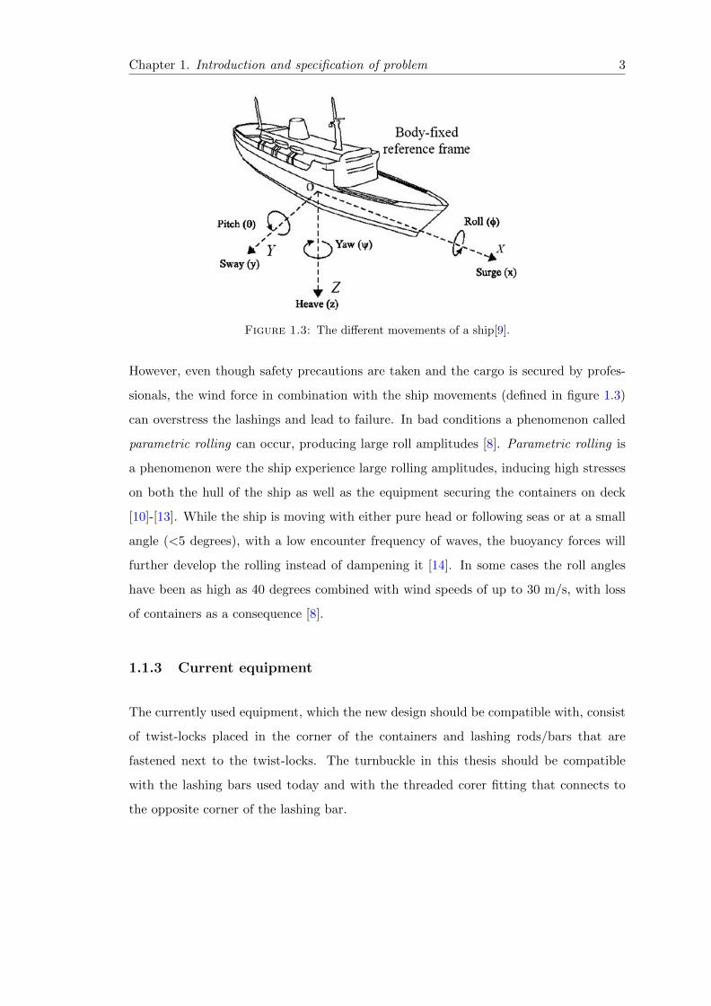
Figure 1.3: The different movements of a ship[9].
However, even though safety precautions are taken and the cargo is secured by profes-
sionals, the wind force in combination with the ship movements (defined in figure 1.3)
can overstress the lashings and lead to failure. In bad conditions a phenomenon called
parametric rolling can occur, producing large roll amplitudes [8]. Parametric rolling is
a phenomenon were the ship experience large rolling amplitudes, inducing high stresses
on both the hull of the ship as well as the equipment securing the containers on deck
[10]-[13]. While the ship is moving with either pure head or following seas or at a small
angle (<5 degrees), with a low encounter frequency of waves, the buoyancy forces will
further develop the rolling instead of dampening it [14]. In some cases the roll angles
have been as high as 40 degrees combined with wind speeds of up to 30 m/s, with loss
of containers as a consequence [8].
1.1.3 Current equipment
The currently used equipment, which the new design should be compatible with, consist
of twist-locks placed in the corner of the containers and lashing rods/bars that are
fastened next to the twist-locks. The turnbuckle in this thesis should be compatible
with the lashing bars used today and with the threaded corer fitting that connects to
the opposite corner of the lashing bar.
Chapter 1. Introduction and specification of problem 4
1.2 Project specification
While securing heavy cargo on for instance a ship, a truck or on trains there is a risk
that the fastening device might break or lose tension. This can result in loss of cargo,
damage to property or, in a worst case scenario, injury to people. There are currently
no cargo-fastening devices that indicate if the tension is above the appropriate level or
if the tension is lost completely.
1.2.1 Definition of problem
Secure heavy cargo with adequate force and maintain it until it’s time for unloading.
While the cargo is secured, the force should be observable at all times to make sure it
is adequate.
1.2.2 Purpose
To find a solution that ensures adequate tension of cargo until unloading.
1.2.3 Goal
The goal of this project is to deliver several concepts and a working design for a new
kind of fastening devices for heavy cargo. The device should be fit for trucks as well
as trains and ships. The device should also indicate when the tension is higher than
intended or when the tension is lost through a sensor.
Chapter 2
Method
2.1 Project planning
The first step of the project was to identify which work packages should be included and
which dependencies there was between them. This work breakdown structure (WBS)
can be seen in appendix A. Following this a time estimation of each task was performed
in order to fit the allotted time for this thesis, which is 30 ECTS credits or 800 hours of
work.
2.1.1 Work Breakdown Structure
The project was divided into the main tasks of a design process, as defined by Johannes-
son et. al.(2004) in their book [15]. The main tasks of the WBS can be seen in table 2.1
and each of these main tasks are divided into subtasks. Some additional main tasks were
identified, such as patent preparation/application and three different presentations, one
held for the receiver of the project, Technogarden Engineering Resources AB, and two
for the project advisor and examiner at Karlstad University. A quarter of the time of
the project was spent on writing the report and the second largest entry, Evaluation of
design, included a ’design-loop’ to ensure that the final design met the criteria listed in
the requirement specification.
5

Chapter 2 Method and theory 6
Table 2.1: The main tasks of the project and the estimated time taken to finish eachtask
Task Name Work
Start-up 36 hrsPre-study 98 hrs
Report 204 hrsConcept development 80 hrs
Patent preparations 12 hrsDesign phase 72 hrs
Half time presentations 12 hrsFinalization of design 84 hrs
Preparation for manufacturing 68 hrsEvaluation of design 104 hrs
Final presentation 30 hrs
Sum 808 hrs
2.2 Problem refinement
The initially identified (see chapter 1) problem was reviewed to achieve a more accurate
and detailed description of the problem. This was done by first expanding the problem
and generalize it to fit all kinds of lashings of goods, ranging from heavy containers on
ships to securing of small boats at a pier. It was then divided into two main categories
of interest and each of these was further divided into detailed areas. The reason for this
was to make sure that the correct problem was solved, as changes in the definition of
the problem late in the design phase will be costly compared to changes in the start
according to Johannesson et. al.(2004) [15]. This eased the task of identifying potential
stakeholders and people to interview that could help narrowing down the problem even
further.
2.2.1 Requirement specification
The identified requirements of the part were divided into Demands and Wishes. The
wishes were weighted between 1 to 5, where 5 was the most important wish and 1
was the least important. The criterias were also divided into five different categories
including Design, Operation, Function, Manufacturing and Life cycle. The different
aspects included in each category are presented in table 2.2 below.

Chapter 2 Method and theory 7
Table 2.2: The aspects of the different categories
Category Aspects included
Design Mechanical properties, environmental conditionsOperation Customers’ use of product
Function The function of the productManufacturing Includes environmental effects and cost
Life cycle Recyclability
2.3 Concept generation
In order to ensure that the final product meets the requirements listed in the requirement
specification the concept generation process was divided into five different steps, as
suggested by Johannesson et. al.(2004) [15].
• Formulate the problem in a broader, abstract, solution-neutral form
• Conduct a function analysis, which divides the main function of the product into
sub-functions
• Seek solutions to the sub-functions
• Combine the alternatives to the sub-functions into a solution
• Sort out potential final solutions
When the sub-problems, which the sub-functions should solve, have been identified and
given several solutions all the different sub-problems are placed in a matrix. In this
matrix, the first column represents the sub-functions of the final product and the rest
of the columns are filled with different proposed solutions to each sub-function. The
next step is to combine the different solutions into a potential final solution and to sort
out the unreasonable combinations and through that reduce the potential solutions to
a smaller number.
The next step is to make use of an elimination matrix and for this thesis Pahl and Beitz
elimination matrix was chosen as initial method for sorting and evaluation of concepts
[15]. An example of this elimination matrix is shown in appendix B.1. The concepts
were then given a plus or minus sign, depending on if they were believed to fulfil the
criteria or not. A plus sign gave a value of +1 and a negative sign gave a value of -1

Chapter 2 Method and theory 8
and all of the concepts with a total value of four or above were put through to the next
round for another, more detailed elimination matrix.
The detailed elimination matrix was evaluated with the help of a reference group and
an example of the matrix can be seen in table 2.3.
Table 2.3: Detailed concept evaluation
Concept → 1 2 3 (ref) 4 5 6
Demands ↓
Design - robust 0 0
DA
TE
0 0 0Design - ergonomic + + 0 - -
Operation 0 + + 0 +Manufacturing 0 0 0 + +
Function + + 0 - -Storing - - 0 0 0
Sum + 2 3 1 1 2
Sum 0 3 2 5 3 2
Sum - 1 1 0 2 2
Net value 1 2 0 1 -1 0
Rank 2 1 4 2 6 4
Further development No Yes No No No No
The limit for passing to the next round was set to a net value of 2 by the reference
group.
2.4 Standards
For the design of the turnbuckle standard ISO-3874 and the Germanischer Lloyd (GL)
classification has been used [16]. Both ISO-3874 and GL has explicit loads to be used
in calculations regarding the strength of the turnbuckle, however the loads from GL are
higher and therefore they’ve been used in calculations in this report.

Chapter 2 Method and theory 9
2.5 Calculations
To ensure structural integrity of the final design, a Finite Element Analysis was carried
out in Ansys. Two parts were included in the analysis, the turnbuckle and a represen-
tational model of a lashing bar. To allow for a finer mesh, while keeping the computing
time at a low level, a symmetrical model was used. The entire model was divided along
a plane intersecting the centre axis, as can be seen in figure 2.1.
Figure 2.1: The half model used in calculations
2.5.1 Mesh
The use of a plane-symmetric method resulted in 231943 elements and 936235 nodes.
The different colors in figure 2.1 represent the sliced bodies used for meshing. Each
body has its own meshing strategy, to allow the mesh to be optimized for each part of
the body since they have different difficulties while meshing. In total there are thirteen
different bodies, which can be seen in figure 2.2. The different techniques used are:
1. Swept with 20 elements in the Z-direction, 2mm face sizing
2. Swept with 10 elements in the X-direction, 3mm face sizing
3. Body sizing of 1mm, hex dominated mesh
4. Body sizing of 2mm, hex dominated mesh
5. Body sizing of 3mm, hex dominated mesh

Chapter 2 Method and theory 10
6. Body sizing of 3mm, hex dominated mesh
7. Body sizing of 1mm, hex dominated mesh
8. Swept with 10 elements in the Z-direction, 4mm face sizing
9. Body sizing of 1mm, hex dominated mesh
10. Body sizing of 1mm, hex dominated mesh
11. Swept with 10 elements in the Z-direction, 1mm face sizing
12. Swept with 10 elements in the Z-direction, 1mm face sizing
13. Body sizing of 3mm, hex dominated mesh
Figure 2.2: The different bodies of the turnbuckle
2.5.2 Contacts
Two different setups were used regarding the contacts of the parts. In the first setup all
contacts were modelled as bonded, meaning that they’re treated as a single body.
In the second setup, all those bodies which are part of the turnbuckle were modelled
as bonded. The contacts between the rod and turnbuckle, however, were modelled as
frictionless contacts, with augmented lagrange formulation and the interface treatment
was set to adjust to touch.
Chapter 2 Method and theory 11
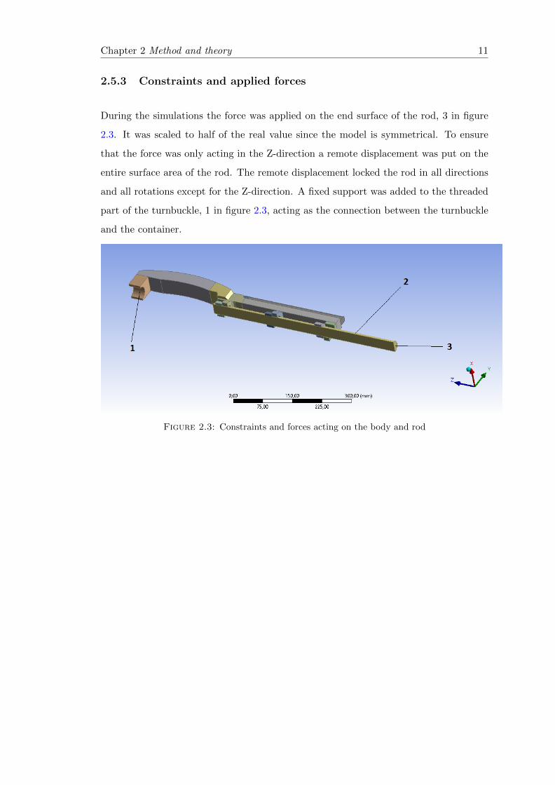
2.5.3 Constraints and applied forces
During the simulations the force was applied on the end surface of the rod, 3 in figure
2.3. It was scaled to half of the real value since the model is symmetrical. To ensure
that the force was only acting in the Z-direction a remote displacement was put on the
entire surface area of the rod. The remote displacement locked the rod in all directions
and all rotations except for the Z-direction. A fixed support was added to the threaded
part of the turnbuckle, 1 in figure 2.3, acting as the connection between the turnbuckle
and the container.
Figure 2.3: Constraints and forces acting on the body and rod

Chapter 3
Results
3.1 Problem Identification
During the pre-study and literature study phase of the project the problem was slightly
altered and re-redefined from the previously presented. It was then defined as:
Identification of turnbuckles which have been exposed to a load above their yield
strength.
3.1.1 Identified sub-problems
As mentioned in chapter 2, the problem was divided into smaller, manageable problems.
These were identified from evaluating the current lashing equipment and through the
study of incident reports regarding container ships. The sub-problems that were found
are presented below:
• A body designed to withstand tensional loads
• Transfer load from lashing rod to turnbuckle
• Transfer load from turnbuckle to corner fitting of container
• Measure pre-tensioning force
• Measure if the SWL (Safe working load) has been exceeded
12
Chapter 3. Results 13
These were then concretized and described with two words, a predicate and a subject,
as described by Johannesson et. al.(2004) [15]. The two last sub-problems were then
combined into one single problem, since they can make use of the same solution. The
two-word problems are listed below:
• Withstand load
• Transmit load (turnbuckle to rod)
• Transmit load (turnbuckle to container corner)
• Measure force
3.1.2 Requirement specification
The requirement specification, divided into the five categories mentioned in chapter 2,
totalled 22 criteria. The requirement specification, and the weights of the wishes, is
presented in table 3.1.

Chapter 3. Results 14
Table3.1:
Req
uir
emen
tsp
ecifi
cati
on
Cri
teri
an
o.
Cate
gory
Cri
teri
aD
em
an
d=
DW
ish
=W
1D
esig
nC
orro
sion
resi
stan
tD
2D
esig
nM
ainta
inad
equ
ate
mec
han
ical
pro
per
ties
from−
20◦ C
to+
60◦ C
D3
Des
ign
Com
ply
wit
hst
and
ard
ISO
3874
D4
Des
ign
Com
ply
wit
hG
erm
anis
cher
Llo
yd
dem
ands
D5
Op
erat
ion
Wei
ght
bel
ow15
kg
[17]
W,
56
Op
erat
ion
Eas
yto
fast
enu
sin
gb
oth
han
ds
W,
57
Op
erat
ion
Exch
anga
ble
’Wea
kest
-lin
k’-
par
tW
,4
8O
per
atio
nA
life
tim
eof
5m
illi
onlo
ad-c
ycl
esD
9O
per
atio
nW
ith
stan
da
fall
of2m
D10
Op
erat
ion
Com
pat
ible
wit
hcu
rren
tla
shin
geq
uip
men
tD
11O
per
atio
nE
rgon
omic
han
dle
for
ten
sion
ing
W,
312
Op
erat
ion
Ten
sion
ing
tob
edon
ew
ith
out
rele
asin
gth
ed
evic
eW
,2
13O
per
atio
nN
otb
ulk
yW
,4
14F
un
ctio
nM
easu
rete
nsi
onin
equ
ipm
ent
D15
Fu
nct
ion
Mea
sure
com
pre
ssio
nin
equ
ipm
ent
W,
516
Fu
nct
ion
Mea
sure
men
tof
smal
lfo
rces
D17
Man
ufa
ctu
rin
gL
owco
stfo
rm
anu
fact
uri
ng
D18
Man
ufa
ctu
rin
gU
seen
vir
onm
enta
lly
frie
ndly
met
hod
sW
,5
19M
anu
fact
uri
ng
Des
ign
suit
able
for
mas
s-p
rod
uct
ion
D20
Lif
ecy
cle
At
leas
t60
%of
the
pro
du
ctsh
ould
be
recy
clab
leD
21L
ife
cycl
eA
tle
ast
85%
ofth
ep
rod
uct
shou
ldb
ere
cycl
able
W,
4

Chapter 3. Results 15
3.2 Concepts
Following the methodology described in section 2.3 and the identified sub-problems from
section 3.1.1 several different concepts were generated for each problem. They were then
combined to create a working concept for the main problem.
3.2.1 The body
Four different concepts were created for the body of the turnbuckle, each with its own
pros and cons and they are all presented below.
3.2.1.1 Concept 1
The first concept for the body of the turnbuckle is an elliptical, egg-shaped, body de-
signed with the force measurement in mind. The idea was to be able to measure the
decreasing distance between the two sides and therefore know the elongation in the
turnbuckle. A model of this can be seen in figure 3.1 below.
Figure 3.1: The first concept for the body

Chapter 3. Results 16
3.2.1.2 Concept 2
The second concept is of a closed, rectangular shape. This simple geometry ensures
easier manufacturing compared to concept 1 and it’s easy to adjust according to each
customers’ wishes. A figure of this design is shown in figure 3.2 below.
Figure 3.2: The second concept for the body
3.2.1.3 Concept 3
Concept 3 is similar to concept 2, with the difference that it’s thinner and instead has
wider parts on the sides to ensure enough stiffness is achieved. The wider parts also
ensures that a good grip can be achieved while tensioning the turnbuckle. It’s shown in
figure 3.3.
Figure 3.3: The first concept for the body
Chapter 3. Results 17
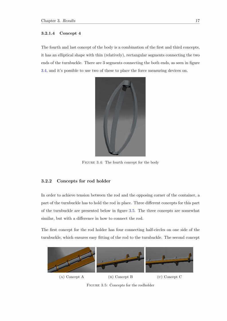
3.2.1.4 Concept 4
The fourth and last concept of the body is a combination of the first and third concepts,
it has an elliptical shape with thin (relatively), rectangular segments connecting the two
ends of the turnbuckle. There are 3 segments connecting the both ends, as seen in figure
3.4, and it’s possible to use two of these to place the force measuring devices on.
Figure 3.4: The fourth concept for the body
3.2.2 Concepts for rod holder
In order to achieve tension between the rod and the opposing corner of the container, a
part of the turnbuckle has to hold the rod in place. Three different concepts for this part
of the turnbuckle are presented below in figure 3.5. The three concepts are somewhat
similar, but with a difference in how to connect the rod.
The first concept for the rod holder has four connecting half-circles on one side of the
turnbuckle, which ensures easy fitting of the rod to the turnbuckle. The second concept
(a) Concept A (b) Concept B (c) Concept C
Figure 3.5: Concepts for the rodholder

Chapter 3. Results 18
has two half-circles on each side of the turnbuckle and four in total. This will make
sure that the turnbuckle stays in place without the users having to hold it in place. The
third concept has every other half-circle on one side and every other on the other side.
This complicates the mounting of the rod to the turnbuckle, but when it’s mounted it
has the best support out of the three concepts.
3.2.3 Concepts for measuring of the force
Two different concepts for the measurement of the force in the turnbuckle have been
developed. One is pure mechanical and the other one is based on electronics and strain
gauges. The idea behind the mechanical concept is to get rid of the sensitive electric
equipment to make the final product more robust. The mechanical concept is based on
an axis sliding within a cylinder, which moves as the body deforms. This requires a good
knowledge of the stiffness of the design, whereas the use of strain gauges measure the
actual strain in the body. The axis will have three different color markings (see figure
3.6) to tell the user when the turnbuckle isn’t pre-tensioned enough, a part where the
pre-tensioning force is adequate and a part where it indicates that the SWL has been
exceeded. The colors chosen are according to Arbetsmiljoverkets regulations, to ensure
that they’re easy for the user to understand[18].
Figure 3.6: The sliding axis within the cylinder
3.2.4 Concepts for transferring the force to the container corner
The concept for transferring the force from the turnbuckle to the corner of the container
is based on the current equipment. It has a heel that fits into the space of the corner
and in the other end there is a threaded part that fits the turnbuckle.

Chapter 3. Results 19
3.2.5 Combined concepts
With all of the above described concepts, a matrix of possible solutions can be generate,
seen in table 3.2 below. The amount of total solutions that can be generated with these
sub-solutions are 24 and they are put into an elimination matrix, appendix B.1, for
further narrowing down of the concepts.
Table 3.2: A matrix over the different sub-solutions
Sub-problem Sub-solution #1 Sub-solution #2
Withstand load Egg-shaped RectangularTransmit load (turnbuckle to rod) All up Half up, half down
Measure force Axis-cylinder Strain gaugesTransmit load(turnbuckle to container) Threaded part
Sub-problem Sub-solution #3 Sub-solution #4
Withstand load Wide rectangle Elliptical shapeTransmit load (turnbuckle to rod) Every other up
Measure forceTransmit load(turnbuckle to container)
3.2.5.1 Elimination of combined concepts
The elimination matrix had six different criteria to evaluate which concepts that were
thought to be possible solutions to the problem. The elimination matrix, and explana-
tions of the concepts, can be seen in table 3.3 below.
Every concept has been given a two letter abbreviation and they’re listed below:
• EG - Egg-shaped body
• RE - Rectangular body
• TR - Thin rectangular body
• EL - Elliptical body
• AU - All rod-connectors under
• HU - Half of the rod-connectors under
• EO - Every other rod-connector under
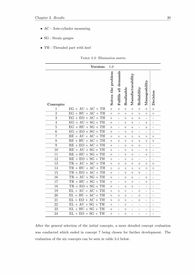
Chapter 3. Results 20
• AC - Axis-cylinder measuring
• SG - Strain gauges
• TH - Threaded part with heel
Table 3.3: Elimination matrix
Version: 1.0
Concepts: Solv
es
the
pro
ble
m
Fu
lfills
all
dem
an
ds
Realizab
le
Manu
factu
rab
ilit
y
Reliab
ilit
y
Man
ageab
ilit
y
Decis
ion
1 EG + AU + AC + TH + + + + + + +
2 EG + HU + AC + TH + + + + + + +
3 EG + EO + AC + TH + - + + + - -
4 EG + AU + SG + TH + - + + - + -
5 EG + HU + SG + TH + - + + - + -
6 EG + EO + SG + TH + - + + - - -
7 RE + AU + AC + TH + + + + + + +
8 RE + HU + AC + TH + + + + + + +
9 RE + EO + AC + TH + - + + + - -
10 RE + AU + SG + TH + - + + - + -
11 RE + HU + SG + TH + - + + - + -
12 RE + EO + SG + TH + - + + - - -
13 TR + AU + AC + TH + + + + + + +
14 TR + HU + AC + TH + + + + + + +
15 TR + EO + AC + TH + - + + + - -
16 TR + AU + SG + TH + - + + - + -
17 TR + HU + SG + TH + - + + - + -
18 TR + EO + SG + TH + - + + - - -
19 EL + AU + AC + TH + + + - + - -
20 EL + HU + AC + TH + + + - + - -
21 EL + EO + AC + TH + + + - + - -
22 EL + AU + SG + TH + - + - - - -
23 EL + HU + SG + TH + - + - - - -
24 EL + EO + SG + TH + - + - - - -
After the general selection of the initial concepts, a more detailed concept evaluation
was conducted which ended in concept 7 being chosen for further development. The
evaluation of the six concepts can be seen in table 3.4 below.

Chapter 3. Results 21
Table 3.4: Detailed concept evaluation
Concept → 1 2 7 (ref) 8 13 14
Demands ↓
Design - robust 0 0
201
4-0
4-1
5
0 0 0Design - ergonomic + + 0 - -
Operation 0 + + 0 +Manufacturing 0 0 0 + +
Function + + 0 - -Storing - - 0 0 0
Sum + 2 3 1 1 2
Sum 0 3 2 5 3 2
Sum - 1 1 0 2 2
Net value 1 2 0 1 -1 0
Rank 2 1 4 2 6 4
Further development No Yes No No No No
3.2.6 Additional concept
During the analysis of the chosen concept, another concept was developed. It was a
combination of concepts 2 and 8 which makes use of the two strengths of each concept.
From concept 2 the egg-shaped part was taken and from concept 8 the rectangular body,
with rectangular cross-sections was taken. They were combined into a single concept
where the part that connects the rod to the turnbuckle was from concept 8 and the
opposite end is from concept 2. A figure of this concept, from here on called concept A,
can be seen below, figure 3.7.
Figure 3.7: Concept A, the additional concept

Chapter 3. Results 22
3.3 Calculations
As mentioned in 2.5.1, 231943 elements and 936235 nodes were used in the calculations.
The areas with highest stresses had a higher concentration of elements, see figure 3.8a.
However in the contact area between the innermost knob and the turnbuckle some
singularities arose. These elements are shown in figure 3.8b.
(a) Mesh concentration in the high-stress area
(b) Some of the singular elements in the contactarea between the knob and the turnbuckle
Figure 3.8: The mesh of the simulated turnbuckle
During the calculations, concept 7 did not meet the requirements listed by GL [16]
without modifications. This contributed to an increased weight to the point where it
did not meet the weight requirement. However, the combined concept, concept A showed
good potential both for withstanding the required forces and measuring the deformation.
Therefore, this concept was further developed and an arc was added connecting the two
sides where the bending force was at its largest. A picture of the stresses in concept A
with focus on the bending stresses can be seen in figure 3.9.
Figure 3.9: Stresses in concept A

Chapter 3. Results 23
From figure 3.9 it can be clearly seen that the stresses in the first body are above the yield
strength of the chosen material (see chapter 3.4). To solve this problem two different
solutions were tested and analysed. The first involved an arc that was added on both
sides of the body to decrease the bending stresses, causing the problems. The results of
this solution can be seen in figure 3.10a. The second geometry had a thicker wall where
the bending stresses were at their highest. The result from the changed geometry can
be seen in figure 3.10b.
(a) Stresses of concept A with the arc
(b) Stresses of concept A with thicker wall
Figure 3.10: Stresses in the two different versions of concept A at breaking load
3.3.1 Force measurement
To measure the deformation, the axis-cylinder concept was placed where the deformation
was at its highest, see figure 3.11. The deformation of the part in the Y-direction was
simulated to 0,73mm at breaking load and 0,55mm at proof load.
Figure 3.11: Deformation along the Y-axis at breaking load
3.4 Material selection and manufacturing
The demands of the material in the turnbuckle, as described by the Germanischer Lloyd
classification [16] states that material must be made out of steel and fulfill the re-
quiremets listed below.

Chapter 3. Results 24
• The steels shall be killed, i.e. completely deoxidized, and fine grain treated
• All products shall be heat treated, that means normalised or quenched and tem-
pered.
• The steels shall fulfil the requirements for impact strength mentioned in the Stan-
dards and approved specifications respectively, at least fulfil the requirements men-
tioned in Table 3.5.
• Unalloyed steels intended for welding shall not have a higher carbon content than
0.22 % (ladle analysis)
• If the type of product requires it, additional non-destructive test can be required.
The table mentioned in the requirements (table 3.5) is regarding the impact strength
of the material at certain temperatures. Since the turnbuckle is to be used above deck,
the lower working temperature to be expected is −20 ◦C [16]. Furthermore the material
Table 3.5: Required impact strengths
Product from
Impact energy
KV 1[J]
minlongitudinal transverse
Rolled products Remin ≥ 235N/mm2 27 (19) 20 (14)
Rolled products Remin ≥ 355N/mm2 34 (24) 24 (17)
Forged steels 27 (19)Cast steels 27 (19)
should be able to withstand corrosion, as specified in the requirement specification (table
3.1). There are several different ways of ensuring corrosion resistance of the final product,
but for this project two different concepts were evaluated. The first concept was having
a corrosion resistant bulk material (e.g. stainless steel) and the second was having a
non-corrosion resistant material in the bulk and then applying a surface treatment in
order to protect the material. However, since no stainless steels are recommended in
GL’s rules for their classification of lashing devices [16], a cast steel was favoured. The
chosen alloy was EN 10083 (42CrMo4) as it is a high-strength steel with good castability.
The final design of the turnbuckle was done with casting as manufacturing method, in

Chapter 3. Results 25
mind. This was to comply with the requirement that the product should be suitable for
mass-production.
3.5 Chosen concept and its functionality
From the FEA-simulations it was concluded that concept A with the additional walls
fulfilled the requirements specified in table 3.1. The highest stress in the part when the
breaking load of 490 kN was applied was 630 MPa, which is below the ultimate yield
strength of the material, see table 3.6. The highest stresses at SWL and PL were 316
MPa and 472 MPa respectively, this can be seen in figures 3.12a and 3.12b.
Table 3.6: Mechanical characteristics of untreated 42CrMo4 steel.[19]
Tensile characteristics Hardness
Yield strength RP0.2 (MPa) Tensile strength Elongation Young’s modulus HV0.1RP0.2 (MPa) Rm (MPa) At (%) E (GPa)
978 1050 16.5 201 356
(a) Stresses at safe working load
(b) Stresses proof load
Figure 3.12: Stresses of the final design at SWL & BL
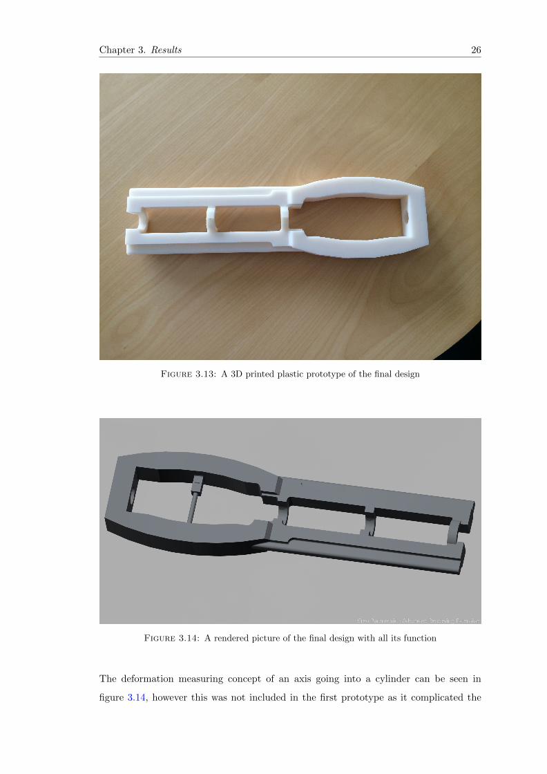
The final weight of the turnbuckle, including the axis and cylinder was 12.5 kg which is
within AMV’s recommendations for lifting by persons in unnatural positions. The final
design is shown in figures 3.13 and 3.14.
Chapter 3. Results 26
Figure 3.13: A 3D printed plastic prototype of the final design
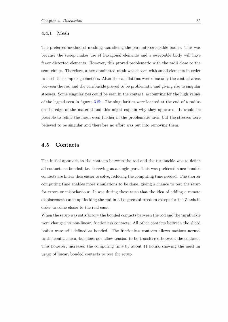
Figure 3.14: A rendered picture of the final design with all its function
The deformation measuring concept of an axis going into a cylinder can be seen in
figure 3.14, however this was not included in the first prototype as it complicated the

Chapter 3. Results 27
manufacturing process. The idea behind this concept is explained in chapter 3.2.3, but
in short the idea is to push a colored cylinder with the axis. When the cylinder is pushed
a certain, pre-determined, length, the user will be able to see a green marking in the
small window of the bigger cylinder. If the cylinder is pushed too far, i.e. the turnbuckle
has deformed more than it’s allowed to, the window will instead show red. This allows
for easy recognition of over-strained turnbuckles which are not safe to use.

Chapter 4
Discussion
4.1 General discussion
4.1.1 Initial goal
The initial goal of the project (see chapter 1.2.3) was to design a device that would fit
trucks as well as trains and ships. However, during the project this goal was revised
to only include large cargo/container ships. This was done in order to narrow down
the problem, making it possible to finish the project within the allotted time. It also
enabled time to be taken to do a thorough pre-study and to produce a single prototype
in plastic, which wouldn’t have been possible if the device was to be compatible with all
three vehicles. It was also decided, early on, that the turnbuckle should be compatible
with the current equipment. This was to ease the introducing of this product on the
market. It was thought that if the users of the turnbuckle had to buy completely new
rods and container connections to be able to use the new turnbuckle, the market would be
reduced. Therefore, compatibility with current lashing equipment was deemed necessary
in order to make sure that there’s a market for the product when it was finished.
4.1.2 Problem
The next step was to identify the main problem with the current equipment and one of
the main problems, since there are several reasons for loss of cargo, was the identification
of faulty / over-strained equipment[6]. With the short times the ships are allowed to
28

Chapter 4. Discussion 29
spend in port, since longer turn-around times in ports means less money earned, the
equipment might not always be inspected thoroughly enough. This can lead to inappro-
priate equipment being used for another trip to save some time while in port.
When the main-problem had been identified and defined (see chapter 3.1) formulating
the sub-problems were the next step of the project. Five different sub-problems were
identified (3.1.1) and these eased the task of solving the main problem. This approach
is solely based on the procedure described by Johannesson et. al.(2004) [15], which is
thought to be a good way to avoid the problem of jumping to conclusions before iden-
tifying the main problem.
The first sub-problem was identified as A body designed to withstand tensional loads and
was written this way to emphasize that the body shouldn’t have to experience com-
pressional loads if compatible with today’s lashing equipment. If using a design of the
turnbuckle and the lashing rod that is capable of resisting compressional loads it would
be possible to relieve the turnbuckle on the other side of the container of some stress.
However, it might induce a problem with bending in the rod, since they’re quite thin
compared to their length. This would introduce several new sub-problems to take into
account while designing the turnbuckle and would at least require a change in the con-
nection between the turnbuckle and the rod.
The second sub-problem concerns the transfer of the load from the lashing rod, which
is connected to the container corner, to the turnbuckle. Three different concepts were
developed for solving this problem, where the one with two semi-circles up and one down
was favoured. This was to ease the task of connecting the rod with the turnbuckle as
having all of the semi-circles on the same side of the turnbuckle would require the user
to hold both the rod and the turnbuckle until some tensioning had been reached. The
concept where every other semi-circle is up and every other is down was not deemed
applicable to the design since it would’ve required a loose fitting between the rod and the
turnbuckle. Without this loose fitting, it would be impossible to attach the rod to the
turnbuckle. A loose fitting between the two parts would also decrease the contact area
between the rod and the turnbuckle as the semi-circles would become smaller. With the
decrease in contact area, the contact pressure would increase. Without reinforcement
of the contact areas, or a material with a relatively, even for steels, high compressional
strength, the contact pressure would lead to large deformations.

Chapter 4. Discussion 30
4.2 Discussion about the concepts
Early on in the thesis it was decided that focus was to be put upon developing a new
body with the ability to measure forces acting on the fastening device. The idea of con-
structing a additional part to be put upon the current equipment was discarded since it
was believed to be hard to implement. The decision to design a new body also enabled
the body to be adapted to a mechanical strain measurement, removing the eletronics
such a strain gauges etc. The urge to remove the electronics existed because there oper-
ational environment above deck on a ship crossing a sea are harsh in terms of electronics.
Since the turnbuckle only has to account for tension, considering the design of the cur-
rent lashing bars, a body consisting of long, thin rods were the first idea to come to
mind. Both concept 2 and 3 were inspired by this idea and the dimensions of them
could’ve been adapted to the required loads. However, since there’s only tensional loads
in them, the force measurement have to be along the axis of the force. This was thought
to complicate the mechanical measurement of the deformation, therefore focus was put
upon developing a body where the largest deformations would be somewhere easier to
measure. This is what originated the ideas for concept 1 and 4, a curved body where
the strain could be measured between the arms.
4.2.1 Pros and cons of body concepts
4.2.1.1 Concept 1
The strength of the first concept comes in its curved outer body and the large cross-
sectional area required to withstand the loads. The curved arms enables the use of a
mechanical strain measurer, as earlier mentioned. Its soft edges, with some additional
rounding, would also make it suitable for e.g. casting.
However, to keep the radii of the outer curves at a value where the deformation is enough
to measure, the body would have to either be wide and long or thin and short. A wide
body would be bulky for the operators to handle and it would increase the weight of
the turnbuckle. The thin and short body would introduce a problem with attaching
the rod to the turnbuckle. It would only be possible to use the first two knobs on the
rod, restricting the usable length of the rod. The reason for this that the rod and the

Chapter 4. Discussion 31
threaded part, connecting the turnbuckle to the container corner, would collide in the
middle while tensioning the device.
4.2.1.2 Concept 2
The second concept makes use of a thin body with long, thin rectangular rods to with-
stand the tensional loads. In figure 3.2 there’s only a single holder for the rod, but with
space available between the rod connector and the threaded end it would be possible
to add several holders to the body. The body could also be changed depending on the
customers’ choice, a long body could have several holders allowing the operator to have
more contact points or adapt the connection depending on the length of the rod.
As earlier mentioned, the use of straight rods for force measurement was considered
problematic as either drilled holes would have to be put in the middle of the area where
the highest stresses are or a device connecting to both ends would have to be used.
Drilled holes in the middle of the load bearing area might introduce a problem with
stress concentrations and be a fracture initiation point. A device connecting on the
outside of both ends would require the movement to be reversed in order to indicate
the deformation in the part. If it wasn’t reversed the whole idea of the colored cylinder
getting stuck when the turnbuckle has been overstrained, falls.
4.2.1.3 Concept 3
This body shares some of the pros with concept 2; it has long thin rods connecting both
ends but they’re wider and thinner than in concept 2. The profit of this are a better
grip for the operator while tensioning the device as the wide flat parts are easy to grip
and that the turnbuckle can be made thinner, which eases storages while it’s not in use.
However, it suffers from the same cons as concept 2 regarding the measurement of the
strain in the component.
4.2.1.4 Concept 4
Concept 4 is the most original concept, with its’ 3 curved arms connecting the two
cylinders. This concept has a obvious path of deformation, so it’s well adapted to the
force measurement.

Chapter 4. Discussion 32
The cons are however several and severe; it’s hard to manufacture in one piece, it’s bulky
and takes up a lot of space during storage. To manufacture it, the arms would have to
be welded to the cylinders introducing several difficulties with alignment of the threaded
part and the rod holder as well as the strength and fatigue properties of the weld.
4.2.2 Rod holders
The three concepts for the rod holder are quite similar, this is due to the requirement
that it has to be compatible with the current lashing equipment. The only difference
between them is how they’re placed, where the concept having half of the half-circles
was favoured. This was because it gives the operator stability and the ability to let go
of the rod once it’s connected to the turnbuckle. This eases the task of tensioning the
device since the operator can use both hands to turn the turnbuckle.
4.2.3 Force measurements
The idea of measuring the instantaneous force in real-time, as specified in section 1.2.1,
was revised and changed to ”Identification of turnbuckles which have been exposed to a
load above their yield strength.”. This changes the requirements of the force measuring
equipment and simplifies the problem since no real-time data has to be transmitted and
processed. The pros of having a mechanical measuring device instead of using electronics
such as strain gauges, are that they’re less sensitive to the harsh environment above deck
on a ship.
To ensure the functionality of the axis-cylinder concept, some further development and
testing is required. Since the ship will experience both roll and pitch (see figure 1.3)
the friction between the colored cylinder and the hole where it slides has to be enough
for it to not move during ship movement. Furthermore, to make sure that the colored
cylinder doesn’t return to its original position when the tension is released, two springed
barbs should be added. These will stop the colored cylinder and show a red color to
the operator, indicating that the turnbuckle should be replaced. Since the deformations
are small (0,55mm at PL and 0,73mm at BL) a magnification of this might have to
used. It can either be in form of a gear ratio, increasing the movement of the cylinder
or a magnifying glass placed above the cylinder in the housing. The gear idea will
however introduce several new problem and an entire design, with many mechanisms

Chapter 4. Discussion 33
would have to be developed. This will increase the manufacturing cost of the part, which
will reduce the attractiveness of the product. Instead focus should be put upon testing
a magnifying glass with the appropriate zoom. This can help make the coloring more
clear to the inspector.
4.2.4 Transmitting the load from the turnbuckle
To transmit the load from the turnbuckle to the container corner, only one concept was
brought forth. This is because the threaded end of the turnbuckle enables the user to
adapt the connection between the turnbuckle and the container corner through the use
of different existing equipment. The connection can be done through using two shorter
rods where one of the rods have a hook in the end and a jaw, with a threaded rod in the
other end, or it can be done through using a part that is designed to fit in the container
corner. This part is a currently used part and is considered to be included in the current
equipment (see chapter 1.1.3).
4.3 Elimination matrices
While putting the concepts through an elimination matrix and grading each of the con-
cepts, a level of subjectiveness is always present. This will influence the weighting of
each concept, possibly leading to a worse concept passing to the next round of elimi-
nation. By using a reference group and discussions while grading the concept, a higher
level of objectiveness was achieved.
During these discussions the problems with the use of strain gauges as force measuring
method was brought forth. The harsh environment on a ship was believed to add a lot
of complexity to the design of the electronics. This was the reason that all concepts
with strain gauges were given a negative value in terms of fulfilling all the demands and
reliability.
In the second, more detailed, elimination matrix, concept number seven was chosen as
reference and the other concepts were weighed against it. All the design were believed
to be equally robust since none of them had any sensitive electronics and were made out
of steel. The ergonomics of the concepts however differed, where concept 1 and 2 with
their egg-shaped body were believed to be more well-suited for the operator than the

Chapter 4. Discussion 34
rectangular body. This was because the rectangular had thinner faces for the operator
to put his hand while tightening the turnbuckle. The thin rectangular body was believed
to be the worst of the bodies. This was because the thin edges was thought to be hard
to grip and might become slippery when wet or covered with ice.
With regard to the operation criteria, the concepts having at least one semi-circle on
the opposite side of the others were favored since it was thought to ease the fastening
procedure, as mentioned in 4.2.2. This also influenced the rating of the function criteria,
where the operator is in focus. If the turnbuckle is easier to fasten, the time taken to
fasten the containers can be reduced, reducing the total time needed in port. The only
negative values that concept 2, the concept that were further developed and that the
final design is based upon, received was under the criteria storing. The egg-shaped outer
of concept 2 will require some more storing space than e.g. the thin rectangular body.
4.4 Calculations
The chosen concept, concept 2, was discarded early on in the calculations when a
new concept was developed, concept A. The new concept was thought to combine the
strengths of concepts 2 and 8, making use of the long, thin part of concept 8 and the
egg-shaped part of concept 2. In the simulations, during the first part where only
bonded contacts were used (see chapter 2.5.2), concept 2 alone required the addition of
more material than the weight requirement allowed. Therefore some weight was saved
by removing half the body and adding half of concept 8’s body. This quickly showed
potential and the decision was taken to move on to frictionless contacts. The most
problematic part of the body was in the connection between the egg and the rectangular
parts, where large bending stresses arose. Two different ideas was brought forth, an
arc and an addition to the wall thickness. Making use of an arc in the final design,
however, would increase the manufacturing complexity and it would also increase the
storing space needed for the turnbuckle. Thereforce, the thicker wall was favored and
adapted to the calculated stresses. In the final design, the weight ended up at 12,15 kg,
which was within the limits specified by AMV [17].
Chapter 4. Discussion 35
4.4.1 Mesh
The preferred method of meshing was slicing the part into sweepable bodies. This was
because the sweep makes use of hexagonal elements and a sweepable body will have
fewer distorted elements. However, this proved problematic with the radii close to the
semi-circles. Therefore, a hex-dominated mesh was chosen with small elements in order
to mesh the complex geometries. After the calculations were done only the contact areas
between the rod and the turnbuckle proved to be problematic and giving rise to singular
stresses. Some singularities could be seen in the contact, accounting for the high values
of the legend seen in figures 3.8b. The singularities were located at the end of a radius
on the edge of the material and this might explain why they appeared. It would be
possible to refine the mesh even further in the problematic area, but the stresses were
believed to be singular and therefore no effort was put into removing them.
4.5 Contacts
The initial approach to the contacts between the rod and the turnbuckle was to define
all contacts as bonded, i.e. behaving as a single part. This was preferred since bonded
contacts are linear thus easier to solve, reducing the computing time needed. The shorter
computing time enables more simulations to be done, giving a chance to test the setup
for errors or misbehaviour. It was during these tests that the idea of adding a remote
displacement came up, locking the rod in all degrees of freedom except for the Z-axis in
order to come closer to the real case.
When the setup was satisfactory the bonded contacts between the rod and the turnbuckle
were changed to non-linear, frictionless contacts. All other contacts between the sliced
bodies were still defined as bonded. The frictionless contacts allows motions normal
to the contact area, but does not allow tension to be transferred between the contacts.
This however, increased the computing time by about 11 hours, showing the need for
usage of linear, bonded contacts to test the setup.
Chapter 4. Discussion 36
4.6 Results
Even though some of the stresses were higher than the ultimate yield strength during
simulations of BL, they are believed to be singular and were excluded from the analysis.
The highest, simulated and non-singular, stresses at BL were 632 MPa, which is below
the yield strength of 978 MPa. Since it is a simulated value, the highest simulated stress
had to be lower than the yield strength in order to be certain no plastic deformation
occurs.
4.7 Manufacturing and material selection
To meet the requirement of having a final design that was suitable for mass-production,
focus was put upon adapting the design for casting. However, in order to make the
turnbuckle fully suitable for casting, further development is needed with regards to the
draft angles of the sides.
It would also be possible to use laser cutting to cut the outline of the turnbuckle and
then machine the semi-circles and the thread in a mill. The choice between laser cutting
and casting the turnbuckle have to be further examined, as the final price of the two
methods depends heavily on production volume. The machining of the part is required
whichever way of manufacturing the body that is chosen, as the semi-circles and the
thread has to be done in a machine in order for the dimensions of the part to be within
the required tolerances. The chosen material was EN 10083 (42CrMo4) since it’s suitable
for both casting and hot-dip galvanizing. Furthermore, it’s mechanical properties allows
weight to be saved since it’s a high-strength steel. The weight saving is crucial in order
to make the turnbuckle easy to handle.
The galvanization of the turnbuckle has to be tested in order to be sure that it provides
adequate protection against the salt water on the ships. This could be done through
acquiring small parts of the material and then galvanize and test them.

Chapter 4. Discussion 37
4.8 Further development
In order to finalize the part and prepare it for being put into production, some further
development is needed. Several of the aspects that need development have been men-
tioned earlier, but the most critical is the axis-cylinder measurement. The resolution on
the current solution is believed to be too small for it to be visible to the inspector/oper-
ator. This solution has to be tested, possibly while performing a proof-test, as defined
by the American Bureau of Shipping , of the turnbuckle.

Chapter 5
Conclusion and recommendations
The final design of the turnbuckle meet the requirements specified by GL according
to calculations, having a highest stress of 630 MPa at BL and 472 MPa at PL. A
concept for the measurement of the force has been developed, but it is in need of further
development before it can be tested. The choice of material and manufacturing method
has to be further considered, taking the market demand into account while choosing
manufacturing method. The surface treatment of the turnbuckle, hot-dip galvanizing,
has to be thoroughly tested to ensure that it will withstand the harsh environment above
deck on a ship.
38

Appendix A
Project Plan
39

Appendix A. Project plan 40
Table A.1: Work breakdown structure
WBS Task Name
1 Start-up
1.1 Specification1.2 Time schedule
2 Pre-study
2.1 Problem identification2.2 Interviews2.3 Research of existing and similar products2.4 Requirement specification
3 Report
3.1 Report structure3.2 Report
4 Concept development
4.1 Concept4.2 Acquire similar products4.3 Product analysis of similar products
5 Patent preparations
5.1 Patent application preparations5.2 Patent application
6 Design phase
6.1 3D-modelling6.2 Development towards DFA / DFM
7 Half time presentations
7.1 Concept presentation7.2 Half-time presentation preparations7.3 Half-time presentation
8 Finalization of design
8.1 Material selection8.2 Structural calculations (FEM)
9 Preparation for manufacturing
9.1 2D-modelling
10 Evaluation of design
10.1 Prototype production10.2 Testing of prototype10.3 Evaluation of results
11 Final presentation
11.4 Opposition11.1 Final presentation of project11.2 Presentation

Appendix B
Elimination Matrix
41

Appendix B. Elimination Matrix 42
Ver
sio
n:
1.0
Concept
Criteria 1
Criteria 2
Criteria 3
Criteria 4
Criteria 5
Criteria 6
Criteria 7
Criteria 8
De
cisi
on
A B C D E F G Sho
rt d
esc
rip
tio
n o
f co
nce
pts
:
A B(+
)(+
)
C(-
)(-
)
D(?
)(?
)
E F G
Elim
inat
ion
cri
teri
a:D
eci
sio
n:
Pro
cee
d w
ith
so
luti
on
Elim
inat
e s
olu
tio
n
Acq
uir
e m
ore
info
Yes
No
Mo
re in
fo n
eed
ed
Elim
inat
ion
mat
rix
Elim
inat
ion
mat
rix
for:
Tu
rnb
uck
le
Co
mm
ents
Figure B.1: Example of elimination matrix based on Pahl and Beitz[15]

Bibliography
[1] United Nations Conference on Trade and Development. Review of Maritime Trans-
port. United Nations Publications, New York, USA, first edition edition, 2013.
[2] A.P. Møller Maersk Group. Interim report 3rd quarter 2013. Interim re-
port, 2013. URL http://files.shareholder.com/downloads/ABEA-3GG91Y/
2936251936x0x706308/9ca47280-2dbe-4407-9211-91aabca80994/Interim_
Report_Q3_2013.pdf. Accessed 3rd February 2014.
[3] A.P. Møller Maersk Group. Vessel overview. Website, 2014. URL http://www.
maerskline.com/sv-se/social/vessel-overview. Accessed 4th February 2014.
[4] World Shipping Council. Containers lost at sea. Survey, August 2011.
URL http://www.worldshipping.org/industry-issues/safety/Containers_
Overboard__Final.pdf. Accessed 3rd February 2014.
[5] Z Radisic. Necessity of proper lashing of containers on the ship’s deck as part of
optimization of the sea voyage. Promet Traffic-Traffico, 16(2), 2004.
[6] Marine Accident Investigation Branch. Report on the investigation of the loss of
cargo containers overboard from p&o nedlloyd genoa. (20), 2006.
[7] L. Andersson. Container lashing. Technology, Law & Insurance, 4(3/4), September
1999.
[8] W.N. France, M. Levadou, T.W Treakle, J.R. Paulling, R.K. Michel, and C. Moore.
An investigation of head-sea parametric rolling and its influence on container lashing
systems. Marine Technology, 40(1):1–19, 2003.
[9] S. Mitra, C.Z. Wang, J.N. Reddy, and B.C. Khoo. A 3d fully coupled analysis of
nonlinear sloshing and ship motion. Ocean Engineering, 39(1):1–13, January 2012.
43

Bibliography 44
[10] BC. Chang. On the parametric rolling of ships using a numerical simulation method.
Ocean Engineering, 35(5):447–457, 2008.
[11] G. Bulian, A. Francescutto, N. Umeda, and H. Hashimoto. Qualitative and quan-
titative characteristics of parametric ship rolling in random waves in the light of
physical model experiments. Ocean Engineering, 35(17):1661–1675, 2008.
[12] G. Bulian. Nonlinear parametric rolling in regular waves—a general procedure for
the analytical approximation of the gz curve and its use in time domain simulations.
Ocean Engineering, 32(3):309–330, 2005.
[13] S. Surendran, SK. Lee, and KH. Sohn. Simplified model for predicting the onset of
parametric rolling. Ocean engineering, 34(3):630–637, 2007.
[14] M. Hamamoto, Y. Kim, and K. Uwatoko. Study on ship motions and capsizing in
following seas. Journal of the Society of Naval Architects of Japan, (170):173–182,
1991.
[15] H. Johannesson, J-G. Persson, and D. Pettersson. Produktutveckling. Liber AB,
Stockholm, first edition edition, 2004.
[16] Germanischer Lloyd SE. Stowage and lashing of containers. 2013.
[17] ARBETSMILJOVERKET. Belaastningsergonomi. Regulation, 2011. AFS 2012:2.
[18] ARBETSMILJOVERKET. Skyltar och signaler. Regulation, 2008. AFS 2008:13.
[19] Mohamed Ali Terres, Nabil Laalai, and Habib Sidhom. Effect of nitriding and
shot-peening on the fatigue behavior of 42crmo4 steel: Experimental analysis and
predictive approach. Materials & Design, 35(0):741 – 748, 2012. ISSN 0261-
3069. doi: http://dx.doi.org/10.1016/j.matdes.2011.09.055. URL http://www.
sciencedirect.com/science/article/pii/S0261306911006807. New Rubber
Materials, Test Methods and Processes.