design of advanced reverse osmosis and … · design of advanced reverse osmosis and nanofiltration...
TRANSCRIPT

DESIGN OF ADVANCED REVERSE OSMOSIS AND NANOFILTRATION MEMBRANES FOR WATER PURIFICATION
BY
CHAOYI BA
DISSERTATION
Submitted in partial fulfillment of the requirements for the degree of Doctor of Philosophy in Materials Science and Engineering
in the Graduate College of the University of Illinois at Urbana-Champaign, 2010
Urbana, Illinois
Doctoral Committee:
Professor James Economy, Chair Professor Phillip H. Geil Associate Professor Jian Ku Shang Assistant Professor Jianjun Cheng

ii
ABSTRACT
Most commercially available reverse osmosis (RO) and nanofiltration (NF)
membranes are based on the thin film composite (TFC) aromatic polyamide
membranes. However, they have several disadvantages including low resistance to
fouling, low chemical and thermal stabilities and limited chlorine tolerance. To
address these problems, advanced RO/NF membranes are being developed from
polyimides for water and wastewater treatments. The following three projects have
resulted from my research.
(1) Positively charged and solvent resistant NF membranes. The use of solvent
resistant membranes to facilitate small molecule separations has been a long standing
industry goal of the chemical and pharmaceutical industries. We developed a solvent
resistant membrane by chemically cross-linking of polyimide membrane using
polyethylenimine. This membrane showed excellent stability in almost all organic
solvents. In addition, this membrane was positively charged due to the amine groups
remaining on the surface. As a result, high efficiency (> 95%) and selectivity for
multivalent heavy metal removal was achieved.
(2) Fouling resistant NF membranes. Antifouling membranes are highly desired
for “all” applications because fouling will lead to higher energy demand, increase of
cleaning and corresponding down time and reduced life-time of the membrane
elements. For fouling prevention, we designed a new membrane system using a
coating technique to modify membrane surface properties to avoid adsorption of
foulants like humic acid. A layer of water-soluble polymer such as polyvinyl alcohol
(PVA), polyacrylic acid (PAA), polyvinyl sulfate (PVS) or sulfonated poly(ether ether
ketone) (SPEEK), was adsorbed onto the surface of a positively charged membrane.
The resultant membranes have a smooth and almost neutrally charged surface which

iii
showed better fouling resistance than both the positively charged NF membranes and
commercially available negatively charged NTR-7450 membrane. In addition, these
membranes showed high efficiency for removal of multivalent ions (> 95% for both
cations and anions). Therefore, these antifouling surfaces can be potentially used for
water softening, water desalination and wastewater treatment in a membrane
bioreactor (MBR) process.
(3) Thermally stable RO membranes. Commercial RO membranes cannot be
used at temperature higher than 45°C due to the use of polysulfone substrate, which
often limits their applications in industries. We successfully developed polyimides as
the membrane substrate for thermally stable RO membranes due to their high thermal
resistance. The polyimide-based composite polyamide membranes showed
desalination performance comparable to the commercial TFC membrane. However,
the key advantage of the polyimide-based membrane is its high thermal stability. As
the feed temperature increased from 25oC to 95oC, the water flux increased 5 - 6 times
while the salt rejection almost kept constant. This membrane appears to provide a
unique solution for hot water desalination and also a feasible way to improve the
water productivity by increasing the operating temperature without any drop in salt
rejection.

iv
To my family for their love and support …

v
ACKNOWLEDGEMENTS
I would like to express my sincere thanks to my advisor, Professor James
Economy, not only for his guidance, inspiration, support and encouragement in every
stage of my Ph.D study, but also for providing me with an excellent atmosphere and
giving me trust and freedom to carry out the research. His vision, optimistic attitude,
enthusiasm and continual pursuing for scientific and industrial challenges have
provided me with lifetime benefits. It is the experience in Professor James Economy’s
group that strengthens my interests in research.
I am so grateful to Prof. Philip Geil, Prof. Jianjun Cheng and Prof. Jian-Ku
Shang in my thesis committee for reading my thesis in their busy schedule.
Many thanks to Economy research group members, especially Dr. Chunqing
Liu, Dr. Zhongren Yue and Jim Langer, for their help and friendship inside and
outside school.
I would like to specially thank Dr. David Ladner in the Department of Civil and
Environmental Engineering at UIUC who cooperated with me on the antifouling
work. This research would not be possible without his help.
I would like to express my gratitude to the business office personnel, Jay
Menacher, Debbie Kluge, Judy Brewer, Betsy Struck, Michelle Malloch, Peggy
Wells, Cindy Brya and Bryan Kieft for all their help through all these years.
I would like to thank Vania Petrova, Scott MacLaren, Rick Haasch, and Julio
Soares for the training of facilities in Frederick Seitz Materials Research Laboratory.
I would also like to thank our sponsor - the WaterCAMPWS, a Science and
Technology Center of Advanced Materials for the Purification of Water with Systems
under the National Science Foundation agreement number CTS-0120978. In the
center, I learned a lot of research in the field of water purification.

vi
Lastly, I would like to thank my parents for their endless love, sacrifice,
support, understanding and encouragement since I was born. I would like to thank my
wife, Ting Liu. She was always there cheering me up and standing by my side. I
would like to thank my son whose birth brings more happiness to my life. I need to
thank my parents-in-law for taking care of my son during my research.

vii
TABLE OF CONTENTS
LIST OF FIGURES ..................................................................................................... xi
LIST OF TABLES .......................................................................................................xv
CHAPTER 1 INTRODUCTION ...................................................................................1 1.1 Reverse osmosis (RO) and nanofiltration (NF) membranes –
materials, structure and limits .........................................................................1 1.2 Membrane formation ......................................................................................4 1.3 Surface modification of membranes ...............................................................6 1.4 Polyimide (PI) materials .................................................................................9 1.5 Objectives and organization of this research ................................................10 1.6 References .....................................................................................................14
CHAPTER 2 CHEMICAL MODIFICATION OF P84 COPOLYIMIDE MEMBRANES BY POLYETHYLENIMINE FOR NANOFILTRATION ............................................................................19
2.1 Introduction ...................................................................................................19
2.2 Experimental .................................................................................................22
2.2.1 Chemicals ..............................................................................................22
2.2.2 Preparation of asymmetric porous membranes ....................................22
2.2.3 Chemical modification of the P84 membranes ......................................22
2.2.4 Nanofiltration tests ................................................................................23
2.2.5 Physical characterization methods .......................................................24
2.2.6 Membrane stability ................................................................................25
2.2.7 Membrane performance for removal of multivalent metal ions ............25
2.3 Results and discussion ..................................................................................26
2.3.1 P84 membrane preparation ...................................................................26
2.3.2 Effect of chemical modification on membrane performance .................26
2.3.3 Effect of modification on membrane morphology ..................................30
2.3.4 Effect of modification on membrane chemistry .....................................32
2.3.5 Thermal properties of the PEI-modified P84 membranes .....................34
2.3.6 Effect of annealing on membrane performance .....................................37
2.3.7 Effect of treatment with organic solvents on membrane performance ...........................................................................................37
2.3.8 Effect of treatment with acids and bases on membrane performance ...........................................................................................38

viii
2.3.9 Membrane performance for removal of multivalent metal ions ............39
2.4 Conclusions ...................................................................................................41
2.5 References .....................................................................................................42
CHAPTER 3 USING POLYELECTROLYTE COATINGS TO IMPROVE FOULING RESISTANCE OF A POSITIVELY CHARGED NANOFILTRATION MEMBRANE ....................................................45
3.1 Introduction ...................................................................................................45
3.2 Experimental .................................................................................................49
3.2.1 Chemicals ...............................................................................................49
3.2.2 Cross-flow apparatus .............................................................................49
3.2.3 Preparation of the positively charged NF membranes (P84-PEI membranes) ...........................................................................................50
3.2.4 Preparation of surface coatings onto the P84-PEI membranes ............51
3.2.5 Removability of the surface coatings by acid or base cleaning .............52
3.2.6 Membrane fouling and cleaning experiments ........................................52
3.2.7 Characterization of surface charge and surface pore size ....................53
3.2.8 Physical characterization methods ........................................................54
3.3 Results and discussion ..................................................................................54
3.3.1 Preparation and characterization of membranes with surface coatings .................................................................................................54
3.3.1.1 Surface chemistry of the P84-PEI NF membrane ...........................54
3.3.1.2 Effect of surface coating on membrane desalination performance .....................................................................................56
3.3.1.3 ATR-FTIR characterization of the stability of the coating layers ...............................................................................................60
3.3.1.4 Effect of surface coating on membrane hydrophilicity and roughness .........................................................................................63
3.3.1.5 Effect of surface coating on membrane charge and pore size ........64
3.3.2 Effect of surface coatings on membrane fouling and cleaning ..............67
3.3.2.1 Fouling behavior of the uncoated P84-PEI membrane ...................67
3.3.2.2 Effect of PVA coating on membrane fouling ...................................69
3.3.2.3 Effect of PVS coating on membrane fouling ...................................70
3.3.2.4 Effect of PAA coating on membrane fouling ...................................72
3.4 Conclusions ...................................................................................................73
3.5 References .....................................................................................................74

ix
CHAPTER 4 DESIGN OF ANTIFOULING NANOFILTRATION MEMBRANES FOR POTENTIAL MEMBRANE BIOREACTOR APPLICATION ................................................................... 79
4.1 Introduction ...................................................................................................79
4.2 Experimental .................................................................................................82
4.2.1 Chemicals ...............................................................................................82
4.2.2 Preparation of partially modified P84 copolyimide membranes with PEI (p-P84-PEI) ............................................................................82
4.2.3 Preparation of PEI modified PMDA-ODA polyimide membranes (PI-PEI) .................................................................................................83
4.2.4 Preparation of surface coatings onto the p-P84-PEI and the PI-PEI membranes .....................................................................................84
4.2.5 Membrane performance measurement ..................................................84
4.2.6 Characterization of the antifouling property of membranes .................85
4.2.7 Fouling resistance of membranes to activated sludge ...........................86
4.2.8 Physical characterization methods ........................................................86
4.3 Results and discussion ..................................................................................87
4.3.1 Preparation and characterization of PVA- or PVS-coated p-P84-PEI NF membranes .......................................................................87
4.3.1.1 Preparation and characterization of p-P84-PEI .............................87
4.3.1.2 Preparation and characterization of PVS- and PVA-coated p-P84-PEI ........................................................................................92
4.3.2 Preparation and characterization of SPEEK-coated PI-PEI NF membranes .............................................................................................94
4.3.2.1 Preparation and characterization of PMDA-ODA polyimide (PI) membranes ...............................................................................94
4.3.2.2 Preparation and characterization of PEI modified polyimide (PI-PEI) NF membranes .................................................................98
4.3.2.3 Preparation and characterization of SPEEK-coated PI-PEI NF membranes ..............................................................................101
4.3.2.4 Characterization of membranes at different preparation stages .............................................................................................103
4.3.2.5 Antifouling property of the PI-PEI/SPEEK membrane in comparison with the PI-PEI and NTR-7450 membranes ..............105
4.3.3 Resistance to activated sludge of the PI-PEI/SPEEK and the P84-PEI/PVS membranes in comparison with the NTR-7450 membrane ............................................................................................108

x
4.4 Conclusions .................................................................................................109
4.5 References ...................................................................................................111
CHAPTER 5 PREPARATION OF PMDA-ODA POLYIMIDE MEMBRANE FOR USE AS SUBSTRATE IN A THERMALLY STABLE COMPOSITE MEMBRANE ...................115
5.1 Introduction .................................................................................................115
5.2 Experimental ...............................................................................................118
5.2.1 Chemicals .............................................................................................118
5.2.2 Preparation of the polyimide membranes ............................................119
5.2.3 Preparation of the composite membranes ...........................................120
5.2.4 Membrane desalination performance measurements ..........................120
5.2.5 Membrane thermal stability measurements .........................................121
5.2.6 Characterization techniques ................................................................121
5.3 Results and discussion ................................................................................123
5.3.1 Effect of ZnCl2 additive on viscosities of the casting solutions ...........123
5.3.2 Preparation and characterization of the polyimide substrate membranes ...........................................................................................125
5.3.2.1 Effect of ZnCl2 additive on membrane morphologies ...................125
5.3.2.2 Effect of ZnCl2 additive on membrane permeability ......................128
5.3.2.3 Characterization of the chemical composition of the polyimide membrane .....................................................................129
5.3.3 Preparation and characterization of the composite membranes using polyimide membranes as substrates ..........................................131
5.3.3.1 Effect of the PI substrate membranes on desalination performance ...................................................................................131
5.3.3.2 Effect of concentration of the monomers on desalination performance ...................................................................................132
5.3.3.3 Effect of immersion time on desalination performance .................135
5.3.3.4 Effect of post annealing on desalination performance ..................136
5.3.4 Thermal stability of the composite membranes ...................................137
5.4 Conclusions .................................................................................................138
5.5 References ...................................................................................................139
AUTHOR’S BIOGRAPHY ......................................................................................143
xi
LIST OF FIGURES
Figure 1.1 Schematic of thin-film-composite (TFC) RO membrane and the chemical structure of the aromatic polyamide thin-film layer [10]. .............................................. 2
Figure 2.1 Cross-sectional (left) and surface (right) morphologies of the P84 membranes developed from four polymer concentrations. .......................................... 27
Figure 2.2 Effect of modification time on the desalination performance of the four P84 membranes. ........................................................................................................... 28
Figure 2.3 Salt rejection sequence of the PEI-modified P84 membrane indicating the positive charge of the membrane. ................................................................................ 29
Figure 2.4 Morphological changes of the P84 membrane cross-sections (left) and surfaces (right) when modified by PEI with various modification times. ................... 31
Figure 2.5 ATR-FTIR spectra of P84 membranes modified by PEI with various modification times. ...................................................................................................... 33
Figure 2.6 Derivative TGA (dTGA) traces of the P84 membranes modified by PEI with various modification times. .................................................................................. 34
Figure 2.7 DSC traces of the P84 membranes modified by PEI with various modification times. ...................................................................................................... 35
Figure 2.8 ATR-FTIR spectra of the PEI-modified P84 membranes before and after heat treatment at various temperatures. ....................................................................... 36
Figure 3.1 Chemical reaction between P84 copolyimide and branched polyethylenimine.......................................................................................................... 55
Figure 3.2 Normalized flux at different stages of the coating/cleaning experiments. (a) Membrane compaction with 2 g/L NaCl solution; (b) flux during coating with 50 mg/L polymer solution; (b′) flux with 2 g/L NaCl solution after coating; (c) flux with 2 g/L NaCl solution after cleaning with HCl solution at pH 2. A pressure of 13.8 bar was applied for all the stages. ...................................................................................... 56
Figure 3.3 ATR-FTIR spectra of the PVA-coated membranes before and after acid (pH 2) or base (pH 9.1) cleaning. ................................................................................ 60
Figure 3.4 ATR-FTIR spectra of the PVS-coated membranes before and after acid (pH 2) or base (pH 9.1) cleaning. ................................................................................ 61
Figure 3.5 ATR-FTIR spectra of the PAA-coated membranes before and after acid (pH 2) or base (pH 9.1) cleaning. ................................................................................ 62
Figure 3.6 AFM images of the uncoated and coated membranes. ............................... 64

xii
Figure 3.7 Rejections to three charged solutes of the four uncoated and coated membranes indicating membrane charge. .................................................................... 65
Figure 3.8 Rejections to three uncharged solutes of the four uncoated and coated membranes indicating relative pore size of these membranes. .................................... 66
Figure 3.9 Normalized flux of the P84-PEI NF membrane during fouling and after cleaning. (a) Membrane compaction with 2 g/L NaCl solution; (b) flux with a solution containing 2 g/L NaCl and 100 mg/L BSA, HA or SA; (c) flux with 2 g/L NaCl solution after cleaning with HCl solution at pH 2. A pressure of 13.8 bar was applied for all the stages. .......................................................................................................... 67
Figure 3.10 Normalized flux of the P84-PEI/PVA membranes during fouling and after cleaning. (a) Membrane compaction with 2 g/L NaCl solution; (b) flux with a solution containing 2 g/L NaCl and 100 mg/L BSA, HA or SA; (c) flux with 2 g/L NaCl solution after cleaning with HCl solution at pH 2. A pressure of 13.8 bar was applied for all the stages. .............................................................................................69
Figure 3.11 Normalized flux of the P84-PEI/PVS membranes during fouling and after cleaning. (a) Membrane compaction with 2 g/L NaCl solution; (b) flux with a solution containing 2 g/L NaCl and 100 mg/L BSA, HA or SA; (c) flux with 2 g/L NaCl solution after cleaning with HCl solution at pH 2. A pressure of 13.8 bar was applied for all the stages. .......................................................................................................... 71
Figure 3.12 Normalized flux of the P84-PEI/PAA membranes during fouling and after cleaning. (a) Membrane compaction with 2 g/L NaCl solution; (b) flux with a solution containing 2 g/L NaCl and 100 mg/L BSA, HA or SA; (c) flux with 2 g/L NaCl solution after cleaning with HCl solution at pH 2. A pressure of 13.8 bar was applied for all the stages. .......................................................................................................... 72
Figure 4.1 Surface morphology of membranes at different preparation stages. .......... 88
Figure 4.2, Effect of modification time on membrane flux. The P84-21% membrane was modified by a 5% PEI/H2O solution at room temperature. .................................. 90
Figure 4.3 Effect of annealing at 90 ˚C on membrane flux. The partially modified P84-21% membrane was annealed to complete reaction. ............................................ 90
Figure 4.4, ATR-FTIR spectra of membranes at different preparation stages. (a) Partially modified P84 (P84-21%) membrane (p-P84-PEI); (b) With PVS coating; (c) with PVA coating. ........................................................................................................ 91
Figure 4.5 Effect of PVS coating on membrane flux. .................................................. 93
Figure 4.6 Effect of PVA coating on membrane flux. ................................................. 93
Figure 4.7 (i) Synthesis of polyimide from polyamic acid precursor via chemical treatment; (ii) Chemical modification route of polyimide with PEI. ........................... 95
Figure 4.8 Effect of propionic acid additive on membrane permeability .................... 95

xiii
Figure 4.9 Cross-sectional (left) and surface (right) morphologies of the polyimide membranes developed from polyamic acid solutions with different amount of propionic acid additive. ................................................................................................ 96
Figure 4.10 Formation of complex between propionic acid and NMP through hydrogen bonding ........................................................................................................ 97
Figure 4.11 Effect of reaction time of polyimide membranes with PEI on the water permeability, NaCl rejection and galactose rejection performance of the PI-20% membrane sample. ....................................................................................................... 98
Figure 4.12 Contact angle of the PEI modified polyimide membranes in dependence on the modification time. ........................................................................................... 100
Figure 4.13 Rejection to various salts as a function of the feed concentration for the PEI modified polyimide membranes. ........................................................................ 101
Figure 4.14 Rejection to various salts as a function of the feed concentration for the SPEEK-coated PI-PEI NF membranes. ..................................................................... 102
Figure 4.15 ATR-FTIR spectra of membranes at different preparation stages. ........ 103
Figure 4.16 SEM spectra of the PI-PEI and the PI-PEI/SPEEK NF membranes. ..... 104
Figure 4.17 Dead-end filtration of model protein solution (bovine serum albumin, 1.0 g/L, 13.8 bar) with PI-PEI, PI-PEI/SPEEK and NTR-7450 ...................................... 106
Figure 4.18 Dead-end filtration of model NOM solution (humic acid, 1.0 g/L, 1 mM CaCl2, 13.8 bar) with PI-PEI, PI-PEI/SPEEK and NTR-7450 .................................. 107
Figure 4.19 Dead-end filtration of model polysaccharide solution (sodium alginate, 1.0 g/L, 13.8 bar) with PI-PEI, PI-PEI/SPEEK and NTR-7450 ................................ 107
Figure 4.20 Dead-end filtration of model activate sludge solution (MLSS: 3000 – 4300 mg/L, 13.8 bar) with PI-PEI/SPEEK, NTR-7450 and P84-PEI/PVS ............... 109
Figure 5.1 Change of viscosities of the PAA solutions by adding ZnCl2. Viscosity was measured using an Ubbelohde Capillary Viscometer in a thermostated water bath at 29.0 ± 0.1 ˚C. ............................................................................................................. 123
Figure 5.2 Possible intermolecular cross-linking structure formed by the interaction between Zn2+ and polyamic acid. ............................................................................... 124
Figure 5.3 Cross-sectional (left) and surface (right) morphologies of the polyimide substrate membranes developed from polyamic acid solutions with different amount of ZnCl2 additive. ....................................................................................................... 126
Figure 5.4 AFM images of the surface morphologies of the polyimide substrate membranes developed from polyamic acid solutions with different amount of ZnCl2 additive. Scanning area: 10 µm×10 µm. .................................................................... 127

xiv
Figure 5.5 Pure water permeability of the polyimide substrate membranes developed from polyamic acid solutions with different amount of ZnCl2 additive. Experiments were conducted at 13.8 bar and room temperature. ................................................... 129
Figure 5.6 ATR-FTIR spectrum of the polyimide membrane after chemical imidization. The membrane was prepared with 24% ZnCl2 additive. ....................... 130
Figure 5.7 XPS survey spectrum of the polyimide membrane after chemical imidization. The membrane was prepared with 24% ZnCl2 additive. ....................... 131
Figure 5.8 SEM images of polyamide thin films prepared with various concentration of TMC....................................................................................................................... 134
Figure 5.9 Effect of operating temperature on membrane performance. Test conditions: 27.6 bar, 2.0 g/L NaCl aqueous solution. ................................................ 137

xv
LIST OF TABLES
Table 2.1 Effect of various modification conditions on membrane performancea ......30
Table 2.2 Effect of annealing on membrane performancea .........................................37
Table 2.3 Effect of treatment by organic solvents on membrane performancea ..........38
Table 2.4 Effect of treatment by acids and bases on membrane performancea ...........39
Table 2.5 Membrane performance for removal of metal ionsa ....................................40
Table 2.6 Rejection of ionic species in a solution containing mixtures of saltsa .........41
Table 3.1 Membrane rejection data at different stages of the coating/cleaning experimentsa. ................................................................................................................59
Table 3.2 Surface properties of the uncoated and coated membranes. ........................63
Table 4.1 Water flux data of membrane at different preparation stagesa. ...................89
Table 4.2 Salt rejection data of membrane at different preparation stagesa. ...............89
Table 4.3 Desalination performance of the various membranes ..................................99
Table 5.1 Effect of different substrate membranes on desalination performancea. ...132
Table 5.2 Effect of monomer concentration on desalination performancea. .............133
Table 5.3 Effect of immersion time in MPDA and TMC on desalination performance. ..............................................................................................................136
Table 5.4 Effect of post thermal treatment on desalination performance. .................136

1
CHAPTER 1
INTRODUCTION
1.1 Reverse osmosis (RO) and nanofiltration (NF) membranes – materials,
structure and limits
The reverse osmosis process which uses polymeric membranes to achieve
selective mass transport has become the simplest and most efficient technique to
desalt the seawater and brackish water [1]. The desalination performance of a RO
membrane depends largely on the membrane material and the membrane structure [2].
An industrially useful RO membrane must exhibit several characteristics such as high
water flux, high salt rejection, mechanical stability, tolerance to temperature variation,
resistance to fouling, and low cost. So far, a number of polymer materials such as
cellulose acetates [3], polyamides [4, 5, 6], crosslinked poly (furfuryl alcohol) [7] and
sulfonated polyethersulfone [8] have been used to make RO membranes. Of these, the
following two have been the most successful.
Cellulose acetate (CA) was the first high-performance RO membrane material
discovered. A typical CA membrane exhibits a flux of 0.9 m3m-2day-1 at 425 psi and
an average NaCl rejection of 97.5% from a 2000 mg/L NaCl feed solution. The main
advantage of CA is its low price and hydrophilic nature which makes it less prone to
fouling. CA also has a good chlorine resistance up to 5 ppm. Thus, today, CA
membranes still maintain a small fraction of the market. However, an inherent
weakness of CA is that it can be eaten by microorganisms. It also slowly hydrolyzes
over time and is generally not used above 35oC [9].

2
Figure 1.1 Schematic of thin-film-composite (TFC) RO membrane and the chemical structure of the aromatic polyamide thin-film layer [10].
A more successful, commercially available RO membrane for desalination is
the thin film composite (TFC) aromatic polyamide membrane. Since it appeared
around 1980, the TFC membranes have dominated the water desalination market
because they show both high flux and very high salt rejection. A typical membrane
exhibits a NaCl rejection of 99.5 % and a flux of 1.2 m3/m2⋅day for a feed solution of
35,000 mg/L NaCl at 800 psi [9]. A typical composite reverse osmosis membrane as
commercially produced today is shown schematically in Figure 1.1 [10]. A base layer
of a woven or a nonwoven fabric is overcoated with a layer of an anisotropic
microporous polymer (usually polysulfone). The surface of the microporous support
is coated with an ultrathin layer of a crosslinked aromatic polyamide. The porous
support provides mechanical strength, whereas the separation is performed by the thin
polyamide top-layer [2]. Still aromatic polyamides have several disadvantages
including:

3
1) Low resistance to fouling. Membrane fouling (scale, silt, biofouling, organic
fouling etc.) is the main cause of permeate flux decline and loss of water quality.
2) Limited oxidant tolerance due to the existence of secondary amides and
electron-rich aromatic rings [11]. Chlorine is commonly used to kill bacteria in water.
However, membrane selectivity is rapidly and permanently lost once exposed to feed
water containing more than a few ppb levels of chlorine or hypochlorite disinfectants,
which means that additional pre-treatment steps to remove chlorine must be taken
before feed water is exposed to polyamide TFC membranes. Thus, today, the world is
still waiting for a good composite membrane for RO and NF, which can tolerate about
20 ppm chlorine or hypochlorite.
3) Low chemical and thermal stabilities. They could hardly be used at
temperature higher than 50oC. They are also hardly used in non-aqueous systems
because the substrate material, polysulfone, can be attacked by many organic solvents
[12, 13]. It should be noted that hot wastewater from the food, chemical and
petroleum processing industries are discharged directly and the energy loss is
estimated at 1-2% of the total energy consumption in the US annually.
Nanofiltration (NF) has often been described as a process between ultrafiltration
and reverse osmosis. Commonly, NF membranes are negatively charged so that they
can efficiently reject multivalent anions such as sulfate and phosphate. The rejection
to monovalent ions such as sodium chloride varies from 20% to 80% depending on
the feed concentration and the material and manufacture of the membranes. NF also
rejects uncharged, dissolved materials with a molecular weight cut-off (MWCO) of
200 – 1000 Dalton. The operating pressure for NF is considerably lower than the one
for RO, which reduces the operating cost significantly. Industrial applications of
nanofiltration are quite common in the food and dairy sector, in chemical processing,

4
in the pulp and paper industry, and in textiles, although the chief application continues
to be in the treatment of fresh, process and waste waters. Membrane materials for NF
include polyethersulfone, polyamides and cellulose derivatives. These materials,
however, quickly lose their stability in contact with organic solvents. They are also
subject to scaling and fouling and have low stability at high temperatures and pH
extremes [2].
Therefore, the development of advanced membranes with higher thermal and
chemical resistance as well as anti-fouling properties is critically required for water
purification.
1.2 Membrane formation
So far, two different techniques have been adopted for the development of
polymeric RO membranes, namely (i) the phase inversion method for asymmetric
membranes and (ii) the interfacial polymerization technique for composite
membranes [14].
Phase inversion is a process in which a polymer in solution is converted to a
solid in a controlled manner. The change in phase can be initiated in a number of
ways, such as solvent evaporation, thermal precipitation, immersion precipitation and
vapor precipitation [15]. In this study, immersion precipitation has been used for
membrane preparation and will be discussed here briefly.
In general, a polymer solution is cast as a film on a support (glass plate or non-
woven fabric) with a casting knife. Then this film is immersed into a coagulation bath
containing a non-solvent. Rapid exchange of solvent and non-solvent occurs with a
consequently rapid phase separation and solidification at the interface. Once the skin
forms, counter-diffusion of the solvent and non-solvent decreases and a highly porous,
open substructure is developed.

5
The membrane morphology and performance are strongly influenced by the
characteristics of the casting solution, such as the polymer concentration, the intrinsic
viscosity and the composition. The introduction of a third component as an additive
into the casting solution has been an effective way to improve the membrane
performance. This additive may have several effects on the membrane formation
process. For example, the viscosity of the polymer solution will be changed. Smid et
al. [16] found that the minimal skin thickness of the membrane is reduced when a
higher intrinsic viscosity of the polymer is used, leading to a decrease in membrane
resistance and an increase in water flux through the membrane. Also, specific
interactions between polymer and additive, solvent and additive, coagulant and
additive, can be induced. The diffusion rate of solvent and non-solvent may be altered
as well. Thus, the membrane development is mostly an empirical process and the
membrane performance is usually optimized based on trial-and-error procedures.
Interfacial polymerization has been employed to prepare a thin layer of cross-
linked polyamide depositing on a substrate ultrafiltration membrane. The performance
of the membrane is mainly determined by the monomers used in the interfacial
polymerization. Even small changes in the monomer’s structure can strongly
influence the membrane properties. So far, the best results were obtained using
trimesoyl chloride and m-phenylene-diamine as monomers [2]. The membrane
performance and morphology is dependent on several synthesis conditions, such as
concentration of reactants, reaction time and post treatments of the resulting films
[17]. Moreover, the surface roughness and pore dimension of the substrate membrane
also have significant effects on the formation of the interfacial film. Generally, a
smooth surface may favor the formation of a thick defect-free active layer. The
resultant composite membrane will give high salt rejection and low flux. On the other

6
hand, a rough surface may result in a thin active layer with some defects. So the
composite membrane may have higher flux with a little sacrifice of salt rejection [18,
19, 20].
1.3 Surface modification of membranes
Surface modification has commonly been used to further improve membrane
performance of the prepared membranes. According to Zeman and Zydney, almost
50% of all MF and UF membranes marketed by 1996 were surface modified.
However, the additive used and procedures followed in commercial membrane
manufacture remain industrial secrets [21, 22]. By physical and/or chemical
modification, membrane chemistry, morphology and pore structure may be altered
resulting in improved selectivity and permeability. Many techniques can be used for
this purpose and will be briefly summarized below.
1. Surface functionalization. Functional groups can be introduced to the
membrane surface by plasma treatment or classical organic reactions like sulfonation.
For example, by oxygen plasma treatment, aromatic polyamide RO membranes
showed improved hydrophilicity and permeability due to the formation of carboxyl
groups [23]. Similar results were observed by low-temperature H2O or CO2 plasma
treatment of polymers such as polysulfone (PSf), polyethersulfone (PES),
polyethylene (PE), polyamide (PA), poly-phenylene ether (PPE), poly(methyl
methacrylate) (PMMA), etc. [24, 25, 26]. Sulfonic goups can be introduced to
polymer membranes by direct reaction of cross-linked membranes based on
polystyrene with concentrated sulfuric acid [27] or by blending polysulfone with
sulfonated polysulfone [28]. Both water flux and salt rejection were thus increased.
Polyacrylonitrile (PAN) membranes could be treated with NaOH or 3-(dimethylamino)
propyl amine which correspondingly generated carboxylic or amine groups

7
respectively. The resultant membranes were either negatively or positively charged
depending on the functional groups and their performance to various salts varied
significantly [29, 30].
2. Cross-linking. Membranes are often prepared from soluble polymers by
phase inversion method. Their solvent resistance is usually low and can be improved
by cross-linking. Several strategies have been reported in the literature including
reaction with di- or tri-functional molecules, hydrolysis by base treatment and UV or
ion-beam irradiation. For example, a membrane prepared from poly(acrylonitrile-co-
glycidyl methacrylate) (PANGMA) with a defined epoxide content was cross-linked
by ammonolysis reaction yielding an extraordinary solvent-resistant and autoclavable
membrane [31]. The PAN membranes became resistant to all common organic
solvents including DMF, DMSO, and NMP after hydrolysis by NaOH, which
provides a candidate material for either the selective layer or the supporting layer for a
solvent resistant composite membrane [32]. Polyimide membranes were modified by
immersing the films in the diamine/methanol solution for a stipulated period of time
[33]. A series of linear aliphatic cross-linking diamine reagents (ethylenediamine,
propane-1,3-diamine, and butane-1,4-diamine) were used. This study demonstrated
for the first time that diamine crosslinked membranes possess high separation
performance and provide impressive separation efficiency for H2/CO2 separation.
Membrane surfaces can also be modified both chemically and physically when they
are exposed to high energy particles. UV/ozone irradiation can break most C-C bonds
and also can induce chain scission and cross-linking on polymer surface [34]. A
commercial sulfonated polysulfone membrane was modified by ion-beam irradiation
[35]. During modification, some of the sulfonic groups on the surface of the
membrane were broken, which resulted in cross-linking of the polymer. These

8
changes modified the surface morphology of the membrane, and also decreased the
negative charge of the membrane. It was observed that fouling of the modified
membrane was significantly less severe than that of the virgin membrane [22].
3. Grafting. Most membrane materials such as polysulfone, polyethersulfone,
polypropylene, polyamide and polyvinylidenefluoride (PVDF) are hydrophobic [36].
Although these membranes have excellent thermal, chemical and mechanical
stabilities, they are easily susceptible to fouling, i.e., nonspecific adsorption of solutes
on the membrane surface and pores resulting in severe flux decline [21, 36].
Therefore the most important purpose of surface modification of membranes is the
improvement of membrane fouling resistance. A common strategy is to graft a layer
of hydrophilic polymer on the membrane. Hydrophilic surfaces have proven to be less
susceptible for fouling and are often reversible [37, 38, 39, 40]. For example,
hydrophilic polyethylene glycol (PEG) chains have often been grafted on commercial
polyamide membranes for fouling improvement [41, 42]. Other grafting monomers
include acrylic acid (AA) [43], N-vinyl pyrrolidone [44], N,N-dimethylaminoethyl
methacrylate (DMAEMA) [45], and 2-acrylamido-2-methyl-1-propanesulfonic acid
(AMPS) [46]. The grafting techniques may include UV photoinitiation [44, 46], redox
initiation [43, 45], and plasma initiation [22, 47].
4. Coating. In grafting, hydrophilic species are covalently bonded to the
membrane surface. Membrane properties are therefore permanently changed and long
term stability of the membranes may be decreased [48]. In coating, however, the
chemistry of the initial membranes is retained and a new layer of hydrophilic film
bearing the antifouling property is coated on top of the membrane surface via
hydrophobic interactions, hydrogen bonding, van der Waals attractions, and
electrostatic interactions [48]. Two coating techniques have been frequently applied,

9
namely dip coating and dynamic coating. In dip coating, the membrane is dipped into
the coating solution and the polymer material is then adsorbed on the membrane
surface [49, 50]. Dynamic coating can be carried out in dead-end or cross-flow modes.
The membranes are loaded in a filtration cell with the surface facing the coating
solution. Then the coating solution is circulated under pressure resulting in the in-situ
formation of a layer of polymer film on the membrane surface [51]. Poly(vinyl
alcohol) (PVA) has been widely used as a coating material for commercial polyamide
membranes to improve their fouling resistance [52, 53]. To increase the chemical,
thermal and mechanical stability of PVA, cross-linking was often conducted by
reacting with aldehydes, anhydrides or diisocyanates etc. [54, 55, 56]. In recent years,
polyelectrolytes have been used as coating materials to modify membrane charge and
hydrophilicity [57]. Such coatings can be multilayer [58] or monolayer [59] and show
high resistance to common organic foulants like proteins and humic substances. If the
fouling still occurs, membrane cleaning can be easily applied to regenerate the
membranes [57, 59].
1.4 Polyimide (PI) materials
Polyimides are the product of a reaction between a dianhydride and a diamine to
produce a soluble polyamic acid, which is thermally or chemically converted to a
polyimide by the loss of water. Typically, polyimides are excellent in thermal stability
due to the stiff aromatic backbones. They are also resistant to a number of solvents
such as aromatics, aliphatics, chlorinated hydrocarbons, ketones, esters and alcohols.
Although polyimides are sensitive to alkalinity, they should be impervious to the pH
encountered in natural feed waters for desalination.
Most polyimides are infusible and insoluble and thus any products, including
membranes, need to be processed from polyamic acid solution. For example,

10
Kapton™ polyimide film is processed from polyamic acid utilizing two monomers
pyromellitic dianhydride (PMDA) and 4,4′-oxydianiline (ODA). The PMDA/ODA
polyimide has a very high glass transition temperature of approximately 400 oC and
excellent resistance to most nonoxidizing acids at room temperature and almost all
organic solvents [60]. Their thermal resistance allows separations to be performed for
a long time at elevated temperatures [61]. Still, there are some soluble polyimides
such as Lenzing P84 prepared from 3,3′,4,4′-benzophenone tetracarboxylic
dianhydride with 80% toluenediisocynate and 20% methylphenylenediisocyanate
(BTDA-TDI/MDI) with a glass transition temperature of 315 oC. Apparently, soluble
polyimides have good processability for membrane development.
A unique feature of polyimides is their chemical reaction with amines, which
results in the opening of some of the imide functions to form ortho-diamide functions.
This reaction can be used to introduce functional groups onto the polyimide
membrane surface by choosing suitable amines. In particular, by reacting with
multifunctional amines (di- or higher functional), PIs can be cross-linked so that the
PI membranes would show improved separation efficiency and solvent resistance.
[62, 63].
1.5 Objectives and organization of this research
The goals of this project are to develop novel RO and nanofiltration (NF)
membranes for desalination and water purification, which will greatly outperform
current state-of-the-art RO/NF membrane systems. During the past 5 years, my
research has been focusing on the development of positively charged and solvent
resistant NF membranes, antifouling NF membranes, and thermally stable RO
membranes. Polyimide materials were used for all the projects.

11
In chapter 2, we described the preparation and characterization of positively
charged NF membranes by chemical modification of the P84 copolyimide asymmetric
membranes using branched polyethylenimine (PEI). Optimized membrane
performance was shown to be 50.9 ± 5.1% salt rejection to a 2.0 g/L NaCl solution
with a flux of 1.2 ± 0.1 m3m-2 day-1 at 13.8 bar and room temperature. The rejection
sequence of CaCl2 > NaCl > Na2SO4 indicates a positive charge at the membrane
surface, which may be attributed to amine groups remaining after the reaction
between PEI and polyimide. Upon modification, the pores of the membranes were
filled with PEI molecules so as to cause the membranes to exhibit nanofiltration
properties. The PEI-modified polyimide membranes likely have a highly cross-linked
structure which makes these membranes stable in various operating environments
including high temperature (100 ◦C), organic solvents, and mild acid and base (2 ≤ pH
≤ 10). These membranes showed efficient removal of multivalent heavy metal ions (>
95%) and may potentially be used for treatment of industrial wastewater.
In Chapter 3, a coating technique was applied to prepare an antifouling
nanofiltration membrane. The positively charged membranes as described in Chapter
2 had low fouling resistance because of the strong adsorption of common foulants via
electrostatic attraction. In order to avoid fouling, a layer of water-soluble polymers
was adsorbed onto the membrane surface in a dynamic manner. With such coatings,
membrane surface properties such as hydrophilicity, roughness and charge were
modified to give improved resistance to fouling. Depending on the coating materials,
the coating layer may be erasable or inerasable. For example, the neutral polymer
polyvinyl alcohol (PVA) may be adsorbed onto the membrane surface by hydrogen
bonding. Such interaction becomes weakened during acid cleaning so that the PVA
layer can be detached. Thus, if membrane fouling occurs, the PVA layer and attached

12
foulants can be removed by acid cleaning to refresh the membrane. Negatively
charged polymers such as polyacrylic acid (PAA) and polyvinyl sulfate (PVS) can be
adsorbed onto the membrane surface by electrostatic force. Such strong interactions
made the coating layers stable during acid cleaning. However, these coating layers
permit removal of the foulants by a simple treatment with acid.
In Chapter 4, we attempted to apply the antifouling NF membranes as designed
in Chapter 3 in a membrane bioreactor (MBR) process. One approach involved the
use of partially PEI modified P84 copolyimide membranes with improved toughness
to develop a series of membranes with various surface properties and separation
capabilities. Another approach dealt with a nearly neutrally charged NF membrane
developed by adsorption of a layer of negatively charged sulfonated poly(ether ether
ketone) (SPEEK) onto the surface of a PEI modified PMDA-ODA polyimide
membrane with positive surface charge. It was found that surface charge had
significant influence on multivalent ion rejection and fouling resistance. The neutrally
charged membrane could remove multivalent ions (both cations and anions) more
efficiently (> 95%) than monovalent ions (80%) due to the size effect; a rejection
sequence of CaCl2 ≈ MgSO4 ≈ Na2SO4> NaCl was observed. When using bovine
serum albumin (BSA), humic acid and sodium alginate as the model foulants, the
neutrally charged membrane exhibited much better fouling resistance than both the
positively and negatively charged membranes. This result suggests that the foulants
would less likely deposit onto a neutral membrane due to the elimination of the charge
interaction between the membrane and the foulants. In addition, the neutrally charged
NF membrane showed better resistance to activated sludge than the commercial NTR-
7450 membrane, which indicates this membrane may be potentially applied in the
MBR process.

13
In Chapter 5, we developed a thermally stable RO membrane using PMDA/ODA
polyimide as a substrate and polyamide as the selective top layer. This substrate
membrane was prepared by immersion precipitation of a casting solution composed of
15% polyamic acid (PAA) and 24% ZnCl2 additive. Zinc ions were able to interact
with the carboxylic groups of PAA forming an ionic cross-linking structure which
facilitated the formation of a membrane with improved surface properties, mechanical
strength and permeability. The PAA membranes were chemically imidized by a
mixture of acetic anhydride and triethylamine at 100 ˚C to prevent pore collapse.
Composite membranes were developed via interfacial polymerization of m-
phenylenediamine (MPDA) and trimesoyl chloride (TMC) on the polyimide
membranes. These composite membranes showed 98% rejection to 2.0 g/L NaCl
solution with a permeation flux of 1.1 m3m-2day-1 at 55.2 bar and room temperature.
This composite membrane demonstrated good thermal stability. As the test
temperature increased from 25 ˚C to 95 ˚C, the permeated flux of 2.0 g/L NaCl
solution increased 5 - 6 times from 0.74 m3m-2day-1 to 3.95 m3m-2day-1 with a stable
rejection rate when the pressure was fixed at 27.6 bar.
In summary, my research involves membrane preparation, characterization and
application. The advanced membranes we have developed can greatly improve the
separation capability of the commercial RO/NF membranes for desalination, water
softening, heavy metal removal and organic removal, etc. They can also withstand
harsh environments including organic solvents, high temperatures, and foulants.
These membranes appear to display great commercial value. Future research can be
conducted on the fundamental study of the antifouling mechanisms and the
application in water purification or wastewater treatment in an MBR process.

14
1.6 References [1] G. Belfort, Synthetic Membrane Processes: Fundamentals and Water
Applications, Academic Press, Orlando, Florida, 1984.
[2] R.J. Petersen, Composite reverse osmosis and nanofiltration membranes, J. Membr. Sci. 1993, 83, 81.
[3] S. Loeb, S. Sourirajan, Sea water demineralization by means of an osmotic membrane, in Saline Water Conversion II, R.F. Gould (ed.)”, Advances in Chemistry Series Number 38, American Chemical Society, Washington, DC, (1963) 117.
[4] J.E. Cadotte, Evaluation of composite reverse osmosis membrane, in Materials Science of Synthetic Membranes, D.R.Lloyd (ed.), ACS Symposium Series Number 269, American Chemical Society, Washington, DC, (1985)
[5] R.E. Larson, J.E. Cadotte, R.J. Petersen, The FT-30 seawater reverse osmosis membrane-element test results, Desalination 38 (1981) 473.
[6] J.E. Cadotte, Interfacially synthesized reverse osmosis membrane, US Patents 4277344 (1981).
[7] M. Kurihara, N. Harumiya, N. Kannamaru, T. Tonomura, M. Nakasatomi, Development of the PEC-1000 composite membrane for single stage sea water desalination and the concentration of dilute aqueous solutions containing valuable materials, Desalination 38 (1981) 449.
[8] A.K. Ghosh, V. Ramachandhran, M.S. Hanra, B.M. Misra, Synthesis, characterization, and performance of sulfonated polyethersulfone nanofiltration membranes, J. Macromol. Sci. Pure Appl. Chem. A39 (3) (2002) 199.
[9] R. W. Baker, Membrane Technology and Applications, 2nd ed., John Wiley & Sons, Ltd., Chichester, 2004.
[10] S.H. Kim, S.-Y. Kwak, T. Suzuki, Positron annihilation spectroscopic evidence to demonstrate the flux-enhancement mechanism in morphology-controlled thin-film-composite (TFC) membrane, Environ. Sci. Technol. 39 (2005) 1764.
[11] J. Glater, S. Hong, M. Elimelech, The search for a chlorine-resistant reverse osmosis membrane, Desalination 95 (1994) 325.
[12] M.J.H. Snow, D. de Winter, R. Buckingham, J. Campbell, J. Wagner, New techniques for extreme conditions: high temperature reverse osmosis and nanofiltration, Desalination 105 (1996) 57.
[13] M. Manttari, A. Pihlajamaki, E. Kaipainen, M. Nystrom, Effect of temperature and membrane pre-treatment by pressure on the filtration properties of nanofiltration membranes, Desalination 145 (2002) 81.

15
[14] I. Pinnau, B.D.Freeman, Formation and modification of polymeric membranes, I.
Pinnau, B.D. Freeman, Eds., ACS Symposium Series 744, American Chemical Society, Washington D.C., 2000, 1.
[15] M.H.V. Mulder, Basic Principles of Memrane Technology, Kluwer, London, 1996.
[16] J. Smid, J.H.M. Albers, A.P.M. Kusters, The formation of asymmetric hollow fiber membranes for gas separation, using PPE of different intrinsic viscosities, J. Membr. Sci. 64 (1991) 121.
[17] C. Wu, S. Zhang, D. Yang, J. Wei, C. Yan, X. Jian, Preparation, characterization and application in wastewater treatment of a novel thermal stable composite membrane, J. Membr. Sci. 279 (2006) 238.
[18] P.S. Singh, S.V. Joshi, J.J. Trivedi, C.V. Devmurari, A.P. Rao, P.K. Ghosh, Probing the structural variations of thin film composite RO membranes obtained by coating polyamide over polysulfone membranes of different pore dimensions, J. Membr. Sci. 278 (2006) 19.
[19] N.-W. Oh, J. Jegal, K.-H. Lee, Preparation and Characterization of nanofiltration composite membranes using polyacrylonitrile (PAN). II. preparation and characterization of polyamide composite membranes, J. Appl. Polym. Sci. 80 (2001) 2729.
[20] M. Hirose, H. Ito, Y. Kamiyama, Effect of skin layer surface structures on the flux behaviour of RO membranes, J. Membr. Sci. 121 (1996) 209.
[21] L.J. Zeman, A.L. Zydney, Microfiltration and Ultrafiltration: Principles and Applications, Marcel Dekker, New York, 1996.
[22] K.C. Khulbe, C. Feng, T. Matsuura, The art of surface modification of synthetic polymeric membranes, J. Appl. Polym. Sci. 115 (2010) 855.
[23] S. Wu, J. Xing, C. Zheng, G. Xu, G. Zheng, J. Xu, Plasma modification of aromatic polyamide reverse osmosis composite membrane surface, J. Appl. Polym. Sci. 64 (1997) 1923.
[24] M.L. Steen, A.C. Jordan, E.R. Fisher, Hydrophilic modification of polymeric membranes by low temperature H2O plasma treatment, J. Membr. Sci. 204 (2002) 341.
[25] S. Pal, S.K. Ghatak, S. De, S. DasGupta, Characterization of CO2 plasma treated polymeric membranes and quantification of flux enhancement, J. Membr. Sci. 323 (2008) 1.
[26] J.M. Grace, L.J. Gerenser, Plasma treatment of polymers, J. Dispersion Sci. Technol. 24 (2003) 305.

16
[27] H. Byun, R. Burford, A. Fane, Sulfonation of cross-linked asymmetric
membranes based on polystyrene and divinylbenzene, J. Appl. Polym. Sci. 39 (1990) 2293.
[28] A. Nabe, E. Staude, G. Belfort, Surface modification of polysulfone ultrafiltration membranes and fouling by BSA solutions, J. Membr. Sci. 133 (1997) 57.
[29] J. Wang, Z. Yue, J. Economy, Novel method to make a continuous micro-mesopore membrane with tailored surface chemistry for use in nanofiltration, J. Membr. Sci. 308 (2008) 191.
[30] J.Wang, Z. Yue, J.S. Ince, J. Economy, Preparation of nanofiltration membranes from polyacrylonitrile ultrafiltration membranes, J. Membr. Sci. 286 (2006) 333.
[31] H.-G. Hicke, I. Lehmanna, G. Malsch, M. Ulbricht, M. Becker, Preparation and characterization of a novel solvent-resistant and autoclavable polymer membrane, J. Membr. Sci. 198 (2002) 187.
[32] J. Wang, Z. Yue, J. Economy, Solvent resistant hydrolyzed polyacrylonitrile membranes, Sep. Sci. Technol. 44 (2009) 2827.
[33] T.-S. Chung, L. Shao, P.S. Tin, Surface modification of polyimide membranes by diamines for H2 and CO2 separation, Macromol. Rapid Commun. 27 (2006) 998.
[34] K. Fujimoto, Y. Takebayashi, H. Inoue, Y. Ikada, Ozone-induced graft polymerization onto polymer surface, J Polym Sci Part A: Polym Chem 31 (1993) 1035.
[35] R. Chennaamsetty, I. Escobar, X. Xu, Characterization of commercial water treatment membranes modified via ion beam irradiation, Desalination 188 (2006) 203.
[36] N. Hilal, O.O. Ogunbiyi, N.J. Miles, R. Nigmatullin, Methods employed for control of fouling in MF and UF membranes: A comprehensive review, Sep. Sci. Technol. 40 (2005) 1957.
[37] A.G. Fane, C.J.D. Fell, A review of fouling and fouling control in ultrafiltration, Desalination 62 (1987) 117.
[38] A.D. Marshall, P.A. Munro, G.Tragardh, The effect of protein fouling in microfiltration and ultrafiltration on permeate flux, protein retention and selectivity - A literature review, Desalination 91 (1993) 65.
[39] K. Kim, K. Saito, S. Furusaki, T. Sugo, J. Okamoto, Water flux and protein adsorption of a hollow fibre modified with hydroxyl groups, J. Membr. Sci. 56 (1991) 289.
[40] A. Nabe, E. Staude, G. Belfort, Surface modification of polysulfone ultrafiltration membranes and fouling by BSA solutions, J Membr. Sci. 133 (1997) 57.

17
[41] G. Kang, M. Liu, B. Lin, Y. Cao, Q. Yuan, A novel method of surface
modification on thin-film composite reverse osmosis membrane by grafting poly(ethylene glycol), Polymer 48 (2007) 1165.
[42] J. Gilron, S. Belfer, P. Väisänen, M. Nyström, Effects of surface modification on antifouling and performance properties of reverse osmosis membranes, Desalination 140 (2001) 167.
[43] V. Freger, J. Gilron, S. Belfer, TFC polyamide membranes modified by grafting of hydrophilic polymers: an FT-IR/AFM/TEM study, J. Membr. Sci. 209 (2002) 283.
[44] J.E. Kilduff, S. Mattaraj, J.P. Pieracci, G. Belfort,Photochemical modification of poly(ether sulfone) and sulfonated poly(sulfone) nanofiltration membranes for control of fouling by natural organic matter, Desalination 132 (2000) 133.
[45] Q. Dai, Z. Xu, H. Deng, Z. Liu, J. Wu, P. Seta, Surface modification of microporous polypropylene membranes by graft polymerization of N, N-dimethylaminoethyl-methacrylate, Chin. J. Polym. Sci. 22 (2004) 369.
[46] N. Hilal, L. Al-Khatib, B.P. Atkin, V. Kochkodan, N. Potapchenko, Photochemical modification of membrane surfaces for (bio)fouling reduction: a nano-scale study using AFM, Desalination 158 (2003) 65.
[47] J. Lai, Y.C. Chao, Plasma-modified nylon 4 membranes for reverse osmosis desalination, J. Appl. Polym. Sci. 39 (1990) 2293.
[48] N. Hilal, O.O. Ogunbiyi, N.J. Miles, R. Nigmatullin, Methods employed for control of fouling in MF and UF membranes: a comprehensive review, Sep. Sci. Technol. 40 (2005) 1957.
[49] S.P. Nunes, M.L. Sforca, K.V. Peinemann, Dense hydrophilic composite membranes for ultrafiltration, J. Membr. Sci. 106 (1995) 49.
[50] F.F. Stengaard, Preparation of asymmetric microfiltration membranes and modification of their properties by chemical treatment, J. Membr. Sci. 36 (1988) 257.
[51] N. Li, Z. Liu, S. Xu, Dynamically formed poly (vinyl alcohol) ultrafiltration membranes with good anti-fouling characteristics, J. Membr. Sci. 169 (2000) 17.
[52] I. Pinnau, J.H. Ly, R.W. Baker, Reverse osmosis membrane and process, US patent 7,490,725 B2 (2009).
[53] J.R. Du, S. Peldszus, P.M. Huck X. Feng, Modification of poly(vinylidene fluoride) ultrafiltration membranes with poly(vinyl alcohol) for fouling control in drinking water treatment, Water Research 43 (2009) 4559.
[54] B. Bolto, T. Tran, M. Hoang, Z. Xie, Crosslinked poly(vinyl alcohol) membranes, Progress in Polymer Science 34 (2009) 969.

18
[55] H.M. Colquhoun, P.J. Williams, A.L. Lewis, Polymer porous structure and
process, US patent 5,698,105 (1997).
[56] H. Hachisuka, K. Ikeda, Reverse osmosis composite membrane and reverse osmosis treatment method for water using the same, US patent 6,413,425 B1 (2002).
[57] W. Shan, P. Bacchin, P. Aimar, M.L. Bruening, V.V. Tarabara, Polyelectrolyte multilayer films as backflushable nanofiltration membranes with tunable hydrophilicity and surface charge, J. Membr. Sci. (2009), doi:10.1016/j.memsci.2009.11.059.
[58] J. Wang, Y. Yao, Z. Yue, J. Economy, Preparation of polyelectrolyte multilayer films consisting of sulfonated poly(ether ether ketone) alternating with selected anionic layers, J. Membr. Sci. 337 (2009) 200.
[59] C. Ba, D.A. Ladner, J. Economy, Using polyelectrolyte coatings to improve fouling resistance of a positively charged nanofiltration membrane, J. Membr. Sci. 347 (2010) 250.
[60] T. Takekoshi, Polyimides—Fundamentals and Applications, M.K. Ghosh and K.L. Mittal (eds), Marcel Dekker, New York, 1996.
[61] H. Ohya, V.V. Kudryavtsev, S.I. Semenova, Polyimide Membranes: Applications, Fabrications, and Properties, Tokyo, Gordon and Breach, 1996.
[62] W. Albrecht, B. Seifert, Th. Weigel, M. Schossig, A. Hollander, Th. Groth, R. Hilke, Amination of poly(ether imide) membranes using di- and multivalent amines, Macromol. Chem. Phys. 204 (2003) 510.
[63] C. Trimpert, G. Boese, W. Albrecht, K. Richau, Th. Weigel, A. Lendlein, Th. Groth, Poly(ether imide) membranes modified with poly(ethylene imine) as potential carriers for epidermal substitutes, Macromol. Biosci. 6 (2006) 274.

19
CHAPTER 2
CHEMICAL MODIFICATION OF P84 COPOLYIMIDE MEMBRANES BY POLYETHYLENIMINE FOR NANOFILTRATION
2.1 Introduction
In the past few decades, nanofiltration (NF) has emerged as an attractive
membrane process for removal of colloidal, organic, and ionic contaminants from
water [1, 2]. Commercial NF membranes are generally prepared as composites
consisting of an ultrathin (< 200 nm) polymeric film deposited onto the surface of a
thick, asymmetric porous supporting membrane (usually polysulfone). To date, thin
film materials have primarily been limited to polyamides prepared by interfacial
polymerization, while some additional polymeric materials such as sulfonated
polyethersulfone (SPES), polyvinyl alcohol (PVA) derivatives, and sulfonated
polyphenylene oxide (SPPO) have also been developed [3]. Although these
membranes provide a variety of separation capabilities, they are generally negatively
charged [4] and multivalent anions, like sulfate and phosphate, are rejected more
effectively than monovalent anions like chloride [1]. Considering the strong influence
of membrane charge on ion permeation due to the Donnan effect [5], it is of interest to
develop positively charged NF membranes with enhanced rejection of multivalent
cations, such as heavy metal ions (e.g. Ni2+, Cu2+, Zn2+, Pb2+) from industrial
wastewater before discharging [6, 7, 8, 9].
In order to prepare positively charged membranes, a common method is to
functionalize the membrane surface with amine and/or ammonium groups. Childs et
al. developed pore-filled NF membranes by in situ chemical cross-linking of

20
poly(vinylbenzyl chloride) or poly(4-vinylpyridine) in the pores of microporous
polypropylene membranes [10]. Polyelectrolyte gels containing either tertiary amine
and quaternary ammonium groups or pyridine and pyridinium groups were formed
within the pores. Xu and Yang developed a composite membrane whose top layer was
prepared by reaction of brominated polyphenylene oxide with a mixture of
trimethylamine and ethylenediamine [11]. The membrane surface in this system
contained a combination of primary, secondary, and tertiary amines and quaternary
ammonium groups. Du and Zhao reported another composite membrane wherein the
top layer was prepared by interfacial crosslinking of poly(N,N-dimethyl-aminoethyl
methacrylate) using p-xylylene dichloride [12]. In this case only tertiary amines and
quaternary ammonium chloride groups were present at the membrane surface.
Recently Wang et al. prepared polyacrylonitrile (PAN) NF membranes by treatment
of PAN ultrafiltration membranes with 3-(dimethylamino)propyl amine [13]. Upon
reaction, tertiary amine groups were introduced at the membrane surface, which made
the membrane positively charged.
Due to their high mechanical strength, good thermal and chemical stability,
polyimides (PIs) have been widely used in various membrane processes for separation
of liquid and gaseous mixtures [14]. A unique feature of PIs is their chemical reaction
with amines, which results in the opening of some of the imide groups to form ortho-
diamide functionalities. This reaction may be used to introduce functional groups onto
the PI membrane surface by choosing suitable amines. In particular, by reacting with
di- or multi-functional amines, PIs can be cross-linked such that the membranes show

21
improved separation efficiency and solvent resistance. For example, Albrecht et al.
studied the surface functionalization of poly(ether imide) membranes by di- and
multivalent amines [15]. It was shown when using high molecular weight
polyethylenimine (PEI) as a modifying agent, poly(ether imide) membranes became
insoluble even in polar aprotic solvents such as N,N-dimethylacetamide (DMAc).
High contents of amine groups were detected, making the membranes more
hydrophilic and positively charged as shown by contact angle and streaming potential
studies, respectively [15, 16].
P84, a co-polyimide of 3,3′,4,4′-benzophenone tetracarboxylic dianhydride with
80% toluenediisocynate and 20% methylphenylenediisocyanate (BTDA-TDI/MDI),
has a high glass transition temperature (Tg) of 315˚C, good resistance to many organic
solvents including toluene, hydrocarbons, alcohols and ketones, as well as good
resistance to a broad range of pH conditions. Chemical modification of P84
membranes via treatment with diamines yields membranes useful for pervaporation
dehydration of isopropanol [17] or for nanofiltration in polar aprotic solvents such as
N,N-dimethylformamide (DMF) and N-methypyrrolidone (NMP) [18]. However, the
diamines may only serve to act as crosslinkers to improve the chemical stability of the
P84 membranes. In this study, we used PEI as the modification agent. In addition to
enhancing membrane stability, this modification provided positively charged NF
membranes due to the free amine groups at the membranes surface. These PEI-
modified P84 membranes showed good performance for removal of salts, especially
multivalent metal ions, from water.

22
2.2 Experimental
2.2.1 Chemicals
27% P84 solution in dimethylformamide (DMF) was purchased from Inspec
Fibers GmbH, Lenzing, Austria and used without further treatment. PEI (Mw: 25,000,
Mn: 10,000) was purchased from Aldrich. All of the organic and inorganic reagents
were of analytical grade and used as received.
2.2.2 Preparation of asymmetric porous membranes
Asymmetric porous P84 membranes were cast using the phase inversion
method [1]. Casting solutions were prepared by diluting the original 27% polymer
solution with DMF to give polymer concentrations of 25%, 23% and 21%. Then, the
polymer solution was cast onto polyester support followed by immediate immersion
into a room temperature water bath. After precipitation, the membranes were kept in
the water bath overnight in order to remove the DMF. The membranes were then
rinsed with and stored in deionized (DI) water prior to further chemical treatment.
2.2.3 Chemical modification of the P84 membranes
Chemical modification was conducted by immersing a membrane into a given
PEI solution at 70˚C for varied amounts of time ranging from 0 to 120 min. The
membrane was then rinsed several times using DI water to remove any loosely bound
PEI, and finally stored in DI water until use. In order to determine the optimal
modification conditions, several PEI solutions were prepared by dissolving PEI in
either DI water, isopropanol, or a mixture of isopropanol and water (volume 1:1) at
concentrations of 0.2%, 1% or 5% (wt/vol).

23
2.2.4 Nanofiltration tests
Desalination performance of the modified P84 membranes was examined using
a dead-end filtration cell (Sterlitech HP4750) and 300 mL of a 2.0 g/L NaCl aqueous
feed solution under 13.8 bar and room temperature. The feed solution was stirred at a
rate of 18.33Hz (1100 rpm) in the cell using a standard magnetic stirrer (Corning
Stirrer/Hot Plate, Model PC-420) to minimize concentration polarization. Each
membrane was compacted at a pressure of 13.8 bar for at least 1 h prior to
measurements to ascertain that a steady state was obtained. The permeated solution
was then refilled into the feed and permeate samples were collected as appropriate.
The permeation flux F was determined by measuring the permeation volume V (5-10
mL, 1.7-3.3% recovery) flowing across the membrane of area A (14.6 cm2) in the
time period Δt, F (m3m-2day-1) = V/(A × Δt). The NaCl concentration was measured
using a Cl- ion selective electrode (Cole-Parmer) with an OAKTON Benchtop Ion 510
Meter. The salt rejection was calculated as R = (1 – Cp/Cf) × 100%, where Cp and Cf
were the concentrations of the permeate and feed solution, respectively. For each data
point, 3-5 membrane samples were tested to give an average value.
Similarly, rejection to CaCl2, NaCl and Na2SO4 at four different initial
concentrations (0.2, 0.5, 1.0 and 2.0 g/L) in aqueous solution was measured in order
to qualitatively determine membrane charge. Concentrations of NaCl and CaCl2 were
measured by a Cl- ion selective electrode and the concentration of Na2SO4 was
measured by a Na+ ion selective electrode (Cole-Parmer).

24
2.2.5 Physical characterization methods
Physical characterization was conducted by attenuated total reflectance Fourier
transform infrared spectroscopy (ATR-FTIR), scanning electron microscopy (SEM),
thermal gravimetric analysis (TGA) and differential scanning calorimetry (DSC). All
membrane samples were dried using the solvent exchange method to prevent the
porous structure from collapsing upon drying. Membranes were immersed in
isopropanol for 24 hours during which time the solvent was refreshed 3 times in order
to displace any water contained in the membranes. Subsequently, isopropanol was
replaced by hexane by the same procedure. Finally, the residual solvent was removed
from the membranes using vacuum prior to further experiments.
ATR-FTIR spectra were collected at room temperature over a scanning range of
600-4000 cm-1 with a resolution of 4.0 cm-1, using a Nexus 670 FT-IR (Thermo
Electron Corporation, Madison, WI) with a Golden Gate™ MKII Single Reflectance
ATR (Specac Inc., Woodstock, GA). The spectrometer was installed with a deuterated
triglycine sulfate-potassium bromide (DTGS-KBr) detector and KBr beamsplitter.
Spectra collection was performed using FT-IR software (OMNIC, Thermo Electron
Corporation, Madison, WI).
SEM images were obtained using a Hitachi S-4700 with 15.0 kV accelerating
voltage. For cross-sectional observations the polyimide layer was peeled off of the
polyester support and fractured after immersion in liquid nitrogen. All samples were
coated by sputtering with gold and palladium before testing.
DSC was performed on a Mettler-Toledo DSC 821e. For each analysis,
approximately 20 mg of sample were accurately weighed (± 0.02 mg) into an

25
aluminum pan, which was then hermetically sealed. DSC traces recorded heat flow
during heating at a rate of 10 ˚C /min over the temperature range 25˚C to 300˚C.
TGA was performed on a Cahn TherMax 500 TGA system. Roughly 100-200
mg of each of the polymer samples were heated from room temperature to 700˚C at a
heating rate of 10 ˚C/min under flowing nitrogen.
2.2.6 Membrane stability
Thermal stability of the membranes was performed by annealing membranes
(previously dried by solvent exchange) at 100 ˚C, 200 ˚C, or 300 ˚C for 2 hours and
comparing the desalination performance of the membranes before and after annealing.
Resistance to organic solvents was evaluated by immersing membranes for 16
hours into one of several representative solvents including tetrahydrofurane (THF),
methanol (MeOH), acetone, DMF, NMP and DMAc. Desalination performance of the
membranes before and after solvent treatment was compared. Resistance to aqueous
solutions of varying pH was evaluated by the same procedure. The pH of these
solutions was adjusted using HCl or NaOH.
2.2.7 Membrane performance for removal of multivalent metal ions
Performance for removal of multivalent metal ions from water was determined
using a feed solution containing either a single salt of ZnCl2, CuCl2, FeCl3 or AlCl3,
or a mixture of ZnCl2/NaCl or FeCl3/NaCl. In order to prevent precipitation, all of the
experiments were carried out at a pH of 2 adjusted by HCl. In the single-salt
experiments, the salt concentration was 10 mM. For the mixtures, several molar ratios
were tested, including 1 mM/10 mM, 10 mM/10 mM and 10 mM/1 mM. The

26
concentration of each metal ion in the permeate solutions was determined by ICP-MS
(PerkinElmer-SCIEX ELAN DRCe ICP-MS).
2.3 Results and discussion
2.3.1 P84 membrane preparation
In order to determine the appropriate polymer concentration for membrane
development, four casting solutions containing 27%, 25%, 23% or 21% polymer were
used to develop the P84 membranes by the phase inversion method. Their cross-
sectional and surface morphologies are shown in Figure 2.1. In all cases, a number of
large parallel finger-like voids can be observed, indicating an instantaneous phase
separation occurred during the precipitation step due to the strong mutual affinity
between water and DMF [19]. As the polymer concentration is decreased, larger
numbers of fingers are observed and the size of the pores at the surface becomes
larger. This may be due to reduced polymer aggregation at lower polymer
concentration [20]. These structural differences have a strong influence on mass
transport through the membrane. As shown in Figure 2.2 (modification time = 0), a
decrease in polymer concentration corresponds to an increase in water permeability.
Negligible salt rejection was observed for the unmodified P84 membranes.
2.3.2 Effect of chemical modification on membrane performance
Chemical modification of the four as-mentioned P84 membranes was carried
out by immersion into a PEI solution prepared by dissolving PEI at 1% concentration
in a mixture of water and isopropanol (volume 1:1) at 70˚C. Figure 2.2 shows the
effect of modification time on the desalination performance of the four P84

27
Figure 2.1 Cross-sectional (left) and surface (right) morphologies of the P84 membranes developed from four polymer concentrations.
membranes. With increasing modification time, salt rejection increased gradually and
finally reached a stable value while permeation flux decreased throughout the range.

28
For each membrane, the optimum desalination performance was observed as the point
where salt rejection just reached the maximum. Using this definition, the 27%
membrane showed its best performance after 20 min modification while the other
three membranes required 90 min to reach their optimal level. Comparing the
optimum desalination performance of the four membranes, a trade-off between salt
rejection and permeation flux can be seen. For example, the membranes developed
from 27% to 21% concentrations showed decreasing rejections in the order of 70.4 ±
2.6% > 48.8 ± 2.0% ≈ 50.9 ± 5.1% > 32.9 ± 4.2% whereas the fluxes increased in the
order of 0.40 ± 0.073 < 0.95 ± 0.28 < 1.2 ± 0.1 < 1.8 ± 0.1 m3m-2day-1, respectively.
We selected the 23% membrane for further studies because both the salt rejection and
permeate flux were reasonably high.
Figure 2.2 Effect of modification time on the desalination performance of the four P84 membranes.

29
The 23% membrane with 90 min modification was measured with regard to its
rejections to CaCl2, NaCl, and Na2SO4 at various concentrations. The results are
shown in Figure 2.3. A rejection sequence of CaCl2 > NaCl > Na2SO4 indicates a
positive charge for the membrane [5]. Additionally, the decrease in salt rejection with
increasing salt concentration is consistent with the Donnan exclusion model. As ionic
strength increases the membrane charge is shielded, resulting in a lower effective
charge and consequently lower salt rejection [13].
0.0 0.5 1.0 1.5 2.00
20
40
60
80
100
Salt concentration (g/L)
Salt
reje
ctio
n (%
)
CaCl2 NaCl Na2SO4
Figure 2.3 Salt rejection sequence of the PEI-modified P84 membrane indicating
the positive charge of the membrane.
No obvious improvements in membrane performance were found when
different solvents and different concentrations of PEI were used during modification.
For example, when water was used as the PEI solvent (see Table 2.1A) the modified
membranes showed very low permeation flux although the salt rejection was slightly
improved. On the other hand, when isopropanol was used high permeation flux and
low salt rejection were obtained. This may be due to increased reactivity of PEI in

30
water versus isopropanol. In addition, with an increase of the PEI concentration from
0.2% to 5% (see Table 2.1B), only slight increase of salt rejection was obtained.
However, the permeation flux decreased 20-fold from 1.6 ± 0.4 m3m-2day-1 to 0.08 ±
0.012 m3m-2day-1. This can be explained by faster reaction in higher PEI
concentration solutions. Thus, it appears different reaction conditions only affected
the overall speed of modification. It is also interesting to note permeation flux could
become very low while there was a limited value of salt rejection. This independent
variation may be explained by the changes of morphology and chemical composition
of the membranes during modification.
Table 2.1 Effect of various modification conditions on membrane performancea
(A) Variation of PEI solventb Solvent of PEI Flux (m3m-2day-1) Salt rejection (%) Water 0.15 ± 0.02 65.5 ± 2.9 Isopropanol 4.1 ± 1.2 27.6 ± 4.5 (B) Variation of PEI concentrationc PEI concentration Flux (m3m-2day-1) Salt rejection (%) 0.2% 1.6 ± 0.4 44.4 ± 7.1 5% 0.08 ± 0.012 55.0 ± 3.2 Notes: aMembranes prepared from 23% concentration; Test condition: 2.0 g/L NaCl aqueous solution, 13.8 bar and room temperature. bReaction condition: 1% PEI, 70˚C, 90min. cReaction condition: PEI in mixture of water and isopropanol (vol 1:1), 70oC, 90min.
2.3.3 Effect of modification on membrane morphology
For SEM analysis, five membrane samples were prepared by immersing the P84
membranes in 1% PEI solution in water and isopropanol mixture (volume 1:1) at
70˚C for 0, 30, 60, 90 and 120 min, respectively. Morphological observations of the
membrane cross-sections and surfaces are displayed in Figure 2.4. The unmodified
membrane (0 min) had a pore size of approximately 10 nm. During the reaction with
PEI, pore size became smaller (30 min) until eventually no pores were observed. It is

31
Figure 2.4 Morphological changes of the P84 membrane cross-sections (left) and
surfaces (right) when modified by PEI with various modification times.

32
possible that the membrane surface becomes covered by a thin layer of PEI.
Meanwhile, the pores may be filled by PEI molecules on account of their diffusion
into the pores and anchoring onto the pore walls. The cross-sectional images show a
relatively dense layer on top of the membranes. For the unmodified membrane, the
thickness of the dense layer was about 100 nm. After 30 min modification, the
thickness of the dense layer increased to approximately 400 nm. With longer
modification time, the top layer of the membrane became less porous and the dense
layer became thicker (120 min). Both the decrease in pore size near the membrane
surface and the increase in thickness of the top dense layer may be responsible for the
decrease in permeation flux observed in the PEI-modified P84 membranes [21].
Initially, PEI molecules may diffuse from both the active layer side and the support
layer side of the membrane. With the surface pore size decreasing, diffusion from the
active layer side would slow gradually. However, diffusion from the support layer
side may continue until the membrane is taken out from the PEI solution.
Consequently, with high concentration of PEI or long modification time the
membrane becomes dense and exhibits low permeation flux [15].
2.3.4 Effect of modification on membrane chemistry
Changes in chemical structure during the modification process were measured
by ATR-FTIR and the results are illustrated in Figure 2.5. For the original P84
membrane, a few characteristic absorption bands were observed at 1778 cm-1
(symmetric C=O stretching, imide I), 1719 cm-1 (asymmetric C=O stretching, imide I)
and 1360 cm-1 (C-N-C stretching, imide II). As the chemical reaction progressed, the

33
4000 3500 3000 2500 2000 1500 1000
4000 3500 3000 2500
1547 cm-1
amide II C-N
1360 cm-1
imide II C-N
1644 cm-1
amide I C=OP84+PEI 120min
P84+PEI 90min
P84+PEI 60min
P84+PEI 30min
P84
Abs
orpt
ion
Wavenumber (cm-1)
1778, 1719 cm-1
imide I C=O
2833 cm-1
CH2 in PEI
2968, 2926cm-1
CH3,CH2 in P84
3267 cm-1
amines
Figure 2.5 ATR-FTIR spectra of P84 membranes modified by PEI with various
modification times.
absorption peaks of the imide I bands gradually diminished and disappeared
altogether after 90 min. Over this same progression, the characteristic peaks of amide
groups at 1644 cm-1 (C=O stretching, amide I) and 1547 cm-1 (C-N stretching, amide
II) appeared and increased progressively [17]. The bands in higher wavenumber
regimes (4000-2500 cm-1) are shown in the inset of Figure 2.5. The absorption peaks
at 2968 cm-1and 2926 cm-1 represent CH3 and CH2 groups of P84 polyimide,
respectively. After reaction with PEI, the absorption band of CH2 group of PEI
appeared at 2833 cm-1 and became stronger with increasing reaction time. The band at
3267 cm-1 (N-H vibrations) indicates the existence of free amine groups. Judging
from the FTIR data, one can conclude that within 90 min of reaction, the imide bonds
were completely transformed into amide bonds, resulting in the amine modifier
covalently bound to the P84 membrane with free amine functionalities. Interestingly,

34
there is a good correlation between the extent of modification and the salt rejection
performance of the membrane. It seems that upon completion of the modification
membrane surface properties such as chemical composition and pore structure
remained constant, which made the membrane show a constant value of salt rejection.
2.3.5 Thermal properties of the PEI-modified P84 membranes
Thermal properties of the P84 membranes before and after modification were
investigated by TGA and DSC, and the results are displayed in Figure 2.6 (dTGA)
and Figure 2.7, respectively. The dTGA trace of the original P84 membrane exhibits
two decomposition peaks. The first one at < 100 ˚C is attributed to the release of
absorbed water [17]. The P84 membrane is thermally stable up to 400 ˚C and
0 100 200 300 400 500 600 700
H2O
P84 (547oC)
P84
P84+PEI 30min
P84+PEI 60min
P84+PEI 90min
P84+PEI 120min
Der
iv. w
eigh
t (%
/ oC)
Temperature (oC)
PEI (350oC)
Figure 2.6 Derivative TGA (dTGA) traces of the P84 membranes modified by
PEI with various modification times.

35
50 100 150 200 250 300
P84+PEI 120min
P84+PEI 90min
P84+PEI 60min
P84+PEI 30min
P84
Endo
ther
mal
Temperature (oC)
180oCRe-imidization
H2O
Figure 2.7 DSC traces of the P84 membranes modified by PEI with various modification times.
degradation of the polymer main chain occurs at 547 ˚C. After modification by PEI,
however, a new peak at 350 ˚C appears and the peak intensity increases with
increasing modification time. This result is in good agreement with the ATR-FTIR
results. That is, with additional reaction time, the membrane takes on more PEI. With
regard to the DSC curves, the original P84 membrane shows only one transition at
roughly 100 ˚C, attributed to the evaporation of absorbed water. After modification,
however, a peak at roughly 180 ˚C gradually appears, corresponding to the reaction of
re-imidization [22]. The DSC curves suggest the chemical structure of the PEI-
modified P84 membrane is stable up to 150 ˚C.
Thermal stability of the membranes was confirmed by ATR-FTIR analysis. The
membranes with 90 min modification were annealed under vacuum for 2 hours at 100
˚C, 200 ˚C and 300 ˚C, respectively. Figure 2.8 gives the ATR-FTIR spectra of these

36
membranes. No absorption due to imide groups can be detected after 100 ˚C
treatment, indicating the chemical structure remained intact at 100 ˚C. After treatment
at 200 ˚C, however, strong imide absorption can be seen and the amide absorption has
almost disappeared, indicating re-imidization, which is in agreement with the DSC
result. The spectrum of the 300 ˚C annealed sample still shows the absorption band of
the CH2 group of PEI at 2822 cm-1, which means the PEI did not burn off completely
at this temperature. On the other hand, with heat treatment at temperature higher than
200 ˚C, sample color was observed to change from light yellow to dark brown and the
membranes became brittle. One possible explanation for this behavior is that the
polymer undergoes backbone scission with incorporation of an amine as an end group
[22].
4000 3500 3000 2500 2000 1500 1000
1775 cm-1, 1707 cm-1
imide I
300oC-2h
200oC-2h
100oC-2h
Abs
orpt
ion
Wavenumber (cm-1)
Before annealing1548 cm-1
amide II
2822 cm-1
CH2 in PEI
Figure 2.8 ATR-FTIR spectra of the PEI-modified P84 membranes before and after heat treatment at various temperatures.

37
2.3.6 Effect of annealing on membrane performance
Desalination performance of the membranes after annealing is shown in Table
2.2. Although annealing has been commonly used for improving membrane
selectivity due to the densification of the selective skins [23], this treatment afforded
no apparent improvement for this system. Instead, the membranes showed good
stability at temperature below 100 ˚C. For example, after 100 ˚C treatment, the salt
rejection and permeation flux were almost unchanged. It is suggested that the PEI-
modified membranes have a rigid cross-linked structure and thus the molecular
movement is limited at this temperature. It should be noted that the decrease in flux
upon drying was likely induced by the shrinking of the nanopores due to the strong
capillary forces [24]. After annealing at 200 ˚C and above, however, pore collapse
may happen due to re-imidization. Thus, the permeation flux became impractically
low for nanofiltration although the salt rejection did increase somewhat.
Table 2.2 Effect of annealing on membrane performancea Annealing temperature (oC) Flux (m3m-2day-1)b Salt rejection (%)b R.T. 0.48 ± 0.20 57.0 ± 0.7 100 0.33 ± 0.07 58.3 ± 4.2 200 0.034 90.5 300 Very low ----- Notes: aMembranes were dried by solvent exchange method and annealing was carried out under vacuum for 2h at various temperature. bTest condition: 2.0 g/L NaCl aqueous solution, 13.8 bar and room temperature.
2.3.7 Effect of treatment with organic solvents on membrane performance
The membrane samples with 90 min modification were treated for 16 hours by
immersion into one of several organic solvents to examine their solvent resistance.
Desalination performance of the membranes before and after treatment is shown in
Table 2.3. It is interesting that both the salt rejection and permeation flux values were
almost unchanged after treatment by THF, methanol, or acetone. Even after treatment

38
with DMF, NMP or DMAc, salt rejection still did not change much. The slightly
decreased permeation flux may be caused by swelling and/or capillary forces induced
by solvent exchange with water. These results suggest both the chemical structure and
the pore dimension of the membrane should have excellent resistance to most organic
solvents, since both of these factors are critical for membrane desalination
performance. This solvent resistance is attributed to the cross-linked structure
resulting from the reaction between the polyimide and the PEI. Thus this type of
membrane shows promise for use in solvent-resistant nanofiltration (SRNF).
Table 2.3 Effect of treatment by organic solvents on membrane performancea
Solvents Before treatment After treatment
Flux (m3m-2day-1)b
Salt rejection (%)b
Flux (m3m-2day-1)b
Salt rejection (%)b
THF 1.22 49.2 1.25 48.5 MeOH 1.22 50.0 1.28 51.0
Acetone 1.28 47.0 1.30 46.1 DMF 1.06 52.1 0.80 51.4 NMP 1.10 50.9 0.80 51.0
DMAc 1.25 48.5 0.70 49.9 Notes: aThe membranes were immersed into various organic solvents for 16h and then immersed into DI water for 2h. bTest condition: 2.0 g/L NaCl aqueous solution, 13.8 bar and room temperature.
2.3.8 Effect of treatment with acids and bases on membrane performance
In order to examine their pH resistance, the membranes were immersed into
aqueous solutions with pH between 0 and 12 for 16 hours. Desalination performance
of the membranes before and after treatment is shown in Table 2.4. It was observed
that at a pH of 0 the membrane became brittle while at a pH of 12 the membrane
gelled, probably due to the degradation of the polymer main chain at both of the pH
extremes. However, under moderate acid and base conditions (2 ≤ pH ≤ 10) the
membranes showed good stability. It should be noted that after acid treatment the

39
membranes had increased salt rejection, while after base treatment the membranes had
reduced salt rejection. This rejection variation may be caused by the change of the
membrane charge strength. Considering the amine groups on the membranes, residual
acid may make the membranes more positively charged whereas residual base may
make them less charged.
Table 2.4 Effect of treatment by acids and bases on membrane performancea
pHb Before treatment After treatment
Flux (m3m-2day-1)c
Salt rejection (%)c
Flux (m3m-2day-1)c
Salt rejection (%)c
0 1.35 45.9 -----d -----d 2 1.15 52.7 1.18 58.0 5 1.25 48.1 1.30 50.3 8 1.28 49.4 1.28 38.7 10 1.38 43.0 1.38 35.7 12 1.25 48.5 -----e -----e
Notes: aThe membranes were immersed into various acids and bases for 16h and then immersed into DI water for 2h. bThe pH was adjusted by HCl and NaOH. cTest condition: 2.0 g/L NaCl aqueous solution, 13.8 bar and room temperature. dMembranes became brittle. eThe top layer exhibited poor mechanical integrity.
2.3.9 Membrane performance for removal of multivalent metal ions
Table 2.5 shows the membrane performance for removal of various metal ions
from water. It can be seen that the membrane shows better rejection to NaCl in acid
condition (72.7%) than in neutral condition (50.9 ± 5.1%). This is because the
membrane became more positively charged in acid. In addition, it can be observed
that with the same anion Cl-, the rejection increases in the order of Na+ < Zn2+ or Cu2+
< Fe3+ or Al3+. Thus, the metal ions with higher valence can be removed more
efficiently, in agreement with the Donnan effect. The flux variation for each salt may
be related to ionic concentrations.

40
Table 2.5 Membrane performance for removal of metal ionsa
Salts Flux (m3m-2day-1)b Rejection (%)b
NaCl 1.16 72.7 CuCl2 1.03 92.9 ZnCl2 0.86 94.5 FeCl3 0.80 98.2 AlCl3 0.92 99.2
Notes: aFeed concentration: 10 mM; pH = 2 adjusted by HCl. bTest pressure: 13.8 bar; permeate concentrations were measured by ICP-MS analysis.
It is also of interest to consider the separation efficiency in a mixture of ions of
different valence. As shown in Table 2.6, the rejection to divalent or trivalent ions
was not significantly affected by the variation of salt concentrations. However, the
rejection to monovalent Na+ ion was reduced in the presence of large amount of Zn2+
or Fe3+. Similar results have been reported in the literature [8]. This ion selectivity
may be determined by several factors, such as the size and charge of each ion, the
concentration of anions and cations, and the shielding of membrane charge by ions in
solution [1]. With large amount of ZnCl2 or FeCl3, the high concentration of counter-
ion Cl- may result in efficient shielding of membrane charge. Although the less
charged membrane may have decreased rejection to all the cations, it has stronger
influence on the monovalent cation (Na+) than on the di- or trivalent ions (Zn2+ or
Fe3+) because of the Donnan effect. On the other hand, the metal ion with higher
valence has a larger hydrated radius and can hold the water molecules more strongly
during filtration [25, 26]. For these reasons, the rejection to Na+ ion was decreased
when mixed with Zn2+ or Fe3+, while the rejection to Zn2+ or Fe3+ was almost
unchanged.

41
Table 2.6 Rejection of ionic species in a solution containing mixtures of saltsa (a) ZnCl2 and NaCl Feed Zn2+
(mM) Feed Na+
(mM) Flux
(m3m-2day-1)b Rejection of
Zn2+ (%)b Rejection of
Na+ (%)b 1 10 0.96 96.0 72.7 10 10 0.91 96.1 57.4 10 1 0.93 97.1 4.8
(b) FeCl3 and NaCl
Feed Fe3+ (mM)
Feed Na+ (mM)
Flux (m3m-2day-1)b
Rejection of Fe3+ (%)b
Rejection of Na+ (%)b
1 10 0.99 78.5 c 69.9 10 10 0.83 97.0 56.7 10 1 0.81 97.1 21.3
Notes: apH = 2 adjusted by HCl. bTest pressure: 13.8 bar; permeate concentrations were measured by ICP-MS analysis. cResult may not be accurate because permeate concentration was close to the test limit.
2.4 Conclusions
This work provided novel positively charged NF membranes via chemical
modification of P84 asymmetric membranes using PEI as modifier. It was observed
that the modification conditions affected both the pore size of the membranes and
their NF properties. For a given P84 membrane, a maximum rejection rate was
observed at a certain modification time after which point no additional benefit was
attained with additional reaction time. On the other hand, the flux continued
decreasing with additional reaction time. It is suggested that the membrane properties
are governed by both the chemistry and morphology of the membrane.
Due to their cross-linked structure, the modified membranes showed good
stability in various conditions, especially in organic solvents and mild acid or base.
This stability is important for application in treatment of industrial wastewater, for
example during cleaning after fouling. These positively charged membranes showed
good performance for multivalent heavy metal removal. Studies are now ongoing to

42
evaluate membrane resistance to fouling, including further modifications to improve
resistance to common foulants, such as natural organic matter (NOM).
2.5 References [1] A.I. Schäfer, A.G. Fane, T.D. Waite (Eds.), Nanofiltration - Principles and
Applications, Elsevier Ltd., 2005.
[2] R.W. Baker (Ed.), Membrane Technology and Applications, John Wiley & Sons, Ltd., Chichester, 2004.
[3] R.J. Petersen, Composite reverse osmosis and nanofiltration membranes, J. Membr. Sci., 83 (1993) 81.
[4] A. Bhattacharya, P. Ghosh, Nanofiltration and reverse osmosis membranes: theory and application in separation of electrolytes, Rev. Chem. Eng. 20 (2004) 111.
[5] J.M.M. Peeters, J.P. Boom, M.H.V. Mulder, H. Strathmann, Retention measurements of nanofiltration membranes with electrolyte solutions, J. Membr. Sci., 145 (1998) 199.
[6] A.W. Mohammad, R. Othaman, N. Hilal, Potential use of nanofiltration membranes in treatment of industrial wastewater from Ni-P electroless plating, Desalination, 168 (2004) 241.
[7] A. Bougen, M. Rabiller-Baudry, B. Chaufer, F. Michel, Retention of heavy metal ions with nanofiltration inorganic membranes by grafting chelating groups, Sep. Purif. Technol., 25 (2001) 219.
[8] S. Alami-Younssi, A. Larbot, M. Persin, J. Sarrazin, L. Cot, Rejection of mineral salts on a gamma alumina nanofiltration membrane application to environmental process, J. Membr. Sci., 102 (1995) 123.
[9] L.M. Ortega, R. Lebrun, J.-F. Blais, R. Hausler, Treatment of an acidic leachate containing metal ions by nanofiltration membranes, Sep. Purif. Technol., 54 (2007) 306.
[10] R.F. Childs, A.M. Mika, A.K. Pandey, C. McCrory, S. Mouton, J.M. Dickson, Nanofiltration using pore-filled membranes: effect of polyelectrolyte composition on performance, Sep. Purif. Technol., 22-23 (2001) 507.
[11] T. Xu, W. Yang, A novel positively charged composite membranes for nanofiltration prepared from poly(2,6-dimethyl-1,4-phenylene oxide) by in situ amines crosslinking, J. Membr. Sci., 215 (2003) 25.

43
[12] R. Du, J. Zhao, Properties of poly(N,N-dimethylaminoethyl methacrylate)/
polysulfone positively charged composite nanofiltration membrane, J. Membr. Sci., 239 (2004) 183.
[13] J. Wang, Z. Yue, J. Economy, Novel method to make a continuous micro-mesopore membrane with tailored surface chemistry for use in nanofiltration, J. Membr. Sci., 308 (2008) 191.
[14] H. Ohya, V.V. Kudryavtsev, S.I. Semenova, Polyimide Membranes: Applications, Fabrications, and Properties, Gordon and Breach, Tokyo, 1996.
[15] W. Albrecht, B. Seifert, Th. Weigel, M. Schossig, A. Hollander, Th. Groth, R. Hilke, Amination of poly(ether imide) membranes using di- and multivalent amines, Macromol. Chem. Phys., 204 (2003) 510.
[16] C. Trimpert, G. Boese, W. Albrecht, K. Richau, Th. Weigel, A. Lendlein, Th. Groth. Poly(ether imide) membranes modified with poly(ethylene imine) as potential carriers for epidermal substitutes, Macromol. Biosci., 6 (2006) 274.
[17] X. Qiao, T.-S. Chung, Diamine modification of P84 polyimide membranes for pervaporation dehydration of isopropanol, AIChE, 52 (2006) 3462.
[18] Y.H. See Toh, F.W. Lim, A.G. Livingston, Polymeric membranes for nanofiltration in polar aprotic solvents. J. Membr. Sci., 301 (2007) 3.
[19] M. Mulder, Basic Principles of Membrane Technology, Kluwer, London, 1996.
[20] K. Boussu, C. Vandecasteele, B. Van der Bruggen, Study of the characteristics and the performance of self-made nanoporous polyethersulfone membranes, Polymer, 47 (2006) 3464.
[21] Y.H. See-Toh, F.C. Ferreira, A.G. Livingston, The influence of membrane formation parameters on the functional performance of organic solvent nanofiltration membranes, J. Membr. Sci., 299 (2007) 236.
[22] C.E. Powell, X.J. Duthie, S.E. Kentish, G.G. Qiao, G.W. Stevens, Reversible diamine cross-linking of polyimide membranes, J. Membr. Sci., 291 (2007) 199.
[23] X. Qiao, T.-S. Chung, K.P. Pramoda, Fabrication and characterization of BTDA-TDA/MDI (P84) co-polyimide membranes for the pervaporation dehydration of isopropanol, J. Membr. Sci., 264 (2005) 176.
[24] W. MacDonald, C.Y. Pan, Method for drying water-wet membranes, US patent 3,842,515 (1974).

44
[25] J. Kielland, Individual activity coefficients of ions in aqueous solutions, J. Am.
Chem. Soc., 59 (1937) 1675.
[26] B. Tansel, J. Sager, T. Rector, J. Garland, R.F. Strayer, L. Levine, M. Roberts, M. Hummerick, J. Bauer, Significance of hydrated radius and hydration shells on ionic permeability during nanofiltration in dead end and cross flow modes, Sep. Purif. Technol., 51 (2006) 40.
45
CHAPTER 3
USING POLYELECTROLYTE COATINGS TO IMPROVE FOULING RESISTANCE OF A POSITIVELY CHARGED NANOFILTRATION
MEMBRANE
3.1 Introduction
Membrane processes are often hindered by fouling due to a buildup of the
material being rejected [1]. As fouling progresses, membrane productivity declines;
higher pressures and thus more energy must be expended to achieve the desired
throughput. Cleaning strategies must be implemented to remove foulant material and
restore productivity. In many cases, however, the fouling is irreversible and the
membrane elements must be replaced [2]. Organic impurities in the water such as
proteins, humic substances, and polysaccharides have been implicated as strong,
irreversible foulants [3]. Such foulants can adsorb to the membrane surface due to
hydrophobic interactions, hydrogen bonding, van der Waals attractions, and
electrostatic interactions [4]. Therefore, an effective method to reduce fouling is to
modify the membrane surface to minimize these adsorptive interactions between
foulant and membrane [3, 4, 5].
Several surface characteristics of membranes are known to be strongly related
to fouling such as hydrophilicity, roughness and charge [6, 7]. It has been generally
acknowledged that membranes with hydrophilic surfaces are less susceptible to
fouling [4, 8, 9]. Membranes with rougher surfaces are observed to be more favorable
for foulant attachment resulting in more extensive fouling and faster fouling rates [7,
10, 11, 12, 13]. For charged organic compounds, electrostatic attraction or repulsion
forces between the component and the membrane, which depend on pH, influence the

46
degree of fouling; when the surface and foulant have similar charge, foulant
adsorption is reduced [14, 15]. Therefore, development of membranes with a smooth
hydrophilic surface that has a surface charge similar to the foulant seems to be
desirable for antifouling purposes [16].
Over the last few years researchers have devised various strategies to modify
membrane surfaces, which can be generally divided into two categories: grafting and
coating [4]. In grafting, hydrophilic species such as polyethylene glycol and
polyacrylic acid can be covalently bonded to the membrane surface by chemical, low-
temperature plasma, or photochemical techniques [17, 18, 19, 20, 21]. Although
surface grafting has shown high fouling resistance, the technique leads to a permanent
change of membrane chemistry and properties. For example, membrane permeability
may be reduced because the grafting layer adds an extra hydraulic resistance [6, 17].
Grafting may also increase manufacturing costs due to process complications, time
consumption, and extensive use of organic solvents and monomers [4]. Compared to
grafting, coating a thin layer of water-soluble polymers or surfactants from solution
by physical adsorption provides certain distinct advantages for surface modification
[22, 23, 24, 25]. Adsorbed coatings are relatively simple to apply, the process can be
performed in existing membrane installations, and the structure of the membrane is
not likely to be affected by the adsorbed molecules. In addition, the type of coating
can be tailored to the specific application of interest [25]. Until now, most studies of
adsorbed coatings have focused on ultrafiltration membranes. Preparation of

47
antifouling nanofiltration membranes using the coating technique has not been
reported.
Depending on adsorption affinity with the membrane surface, the adsorbed
coating layer can be stable or erasable. Thin films formed through layer-by-layer
(LbL) deposition of positively and negatively charged polyelectrolytes show good
stability due to electrostatic attraction among the membrane surface and the deposited
layers [26]. These multilayer polyelectrolyte films have previously been deposited on
ultrafiltration substrate membranes to prepare composite membranes for nanofiltration
[26, 27]. Although anti-fouling properties of the LbL membranes are still rarely
reported [28], this type of membrane may potentially have high fouling resistance due
to the hydrophilicity of the applied polyelectrolytes and controllable surface charge
[29]. On the other hand, hydrogen-bonded layer-by-layer films have attracted
considerable attention in recent years because the hydrogen bonding can be altered by
changes in solution pH and thus the films can be erased and replaced [30, 31, 32, 33,
34]. When applying this erasable film to the membrane surface, any foulant material
that deposits on top of the film could be effectively removed by detaching the film
from the membrane surface, which leaves behind a clean membrane. It may be much
easier and more cost-effective to remove and replace the film instead of replacing the
membrane. To the authors’ knowledge, such an application has not been previously
proposed.
In a previous study, positively charged nanofiltration membranes were
developed by chemical modification of P84 copolyimide membranes using branched

48
polyethylenimine (PEI) [35]. The PEI-modified polyimide membranes (P84-PEI
membranes) have a highly cross-linked structure which makes these membranes
stable in various operating environments including high temperature (100˚C), organic
solvents, and mild acid and base (2 ≤ pH ≤ 10). Meanwhile, due to the Donnan
repulsion effect, these membranes showed efficient removal of multivalent heavy
metal ions (> 95%) and may potentially be used for treatment of industrial
wastewater.
In the present study, the P84-PEI membranes were further modified by
adsorption of a layer of polymers from a dilute solution in a dynamic manner [36].
Polyvinyl alcohol (PVA), polyacrylic acid (PAA) and polyvinyl sulfate-potassium salt
(PVS), were tested as modifying agents. The effect of these coatings on membrane
surface roughness and hydrophilicity was characterized by atomic force microscopy
(AFM) and contact angle measurements. The charge and pore size of the unmodified
and modified membranes were qualitatively analyzed using ions and uncharged
sugars as probes. Stability of the coating layers during acid or base cleaning was
studied by attenuated total reflectance Fourier transform infrared spectroscopy (ATR-
FTIR). Fouling experiments were carried out in a cross-flow setup using three model
foulants, bovine serum albumin (BSA), sodium alginate (SA) and humic acid sodium
salt (HA) representative of proteins, polysaccharides and natural organic matter
(NOM). The effect of the polymer coatings for fouling prevention was tested with
respect to both the reduction of flux decline and the cleanability by acid after fouling.

49
3.2 Experimental
3.2.1 Chemicals
P84 powder was purchased from HP Polymer Inc. and dried in vacuum at
160˚C for 12 hours before use. PEI (MW: 25,000), PVA (MW: 89,000 - 98,000),
PAA (MW: 250,000) and PVS (MW: 170,000) were purchased from Aldrich. Three
dilute coating solutions with concentrations of 50 mg/L were prepared by dissolving
PVA, PAA or PVS in deionized (DI) water at 80˚C overnight. The PVS solution was
filtered before use to remove the insoluble impurities. The pH of the PVA, PAA and
PVS solutions were 5.7, 4.7, and 5.8, respectively. No pH adjustment was made. The
model foulants, BSA (MW: 66,000, ≥98%, Sigma), HA (sodium salt, Aldrich) and SA
(Fluka) were used without further treatment. A concentration of 100 mg/L was
applied for all the fouling experiments and the pH of these foulant solutions were 6 - 7
without any adjustment. Three sugars, D-(+)-galactose (Sigma-Aldrich, ≥99%), D-
(+)-maltose monohydrate (Sigma-Aldrich, ≥99%) and D-(+)-raffinose pentahydrate
(Sigma, ≥99%), were used as received. All of the other inorganic reagents including
HCl, NaOH, NaCl, Na2SO4, CaCl2 were of analytical grade and used as received.
3.2.2 Cross-flow apparatus
A cross-flow system was used for the dynamic coating of polyelectrolyte on
membrane surfaces and the following fouling experiments. The system was
continuous, able to achieve steady state, and allowed for long-term operation. The
cross-flow unit was designed as described in a concurrent study [37]. Running the
experiment involved placing a rectangular (19.1 cm × 14.0 cm) flat sheet membrane
of 140 cm2 active area into a permeation cell (SEPA II, GE Osmonics) and securing it

50
with an O-ring and a hydraulic press. A pump was used to circulate the feed solution
with a flow rate of around 800 mL/min regulated by the variable-frequency motor.
The trans-membrane pressure was controlled by a metering valve installed in the
concentrate line immediately after the membrane cell. The operating temperature was
controlled between 20 and 21˚C by a heat exchanger. For measurement of permeate
flux, the permeate was fed into a collection vessel mounted on a balance. Balance
measurements were logged automatically by the data acquisition/control system. For
continuous balance measurements, a self-emptying collection vessel was used. Data
analysis was performed with programs written in Matlab. Salt rejection was calculated
as R = (1 – σp/σf) × 100%, where σp and σf were the conductivity of the permeate and
the feed, respectively. Conductivity was measured with a bench-top conductivity
meter (Oakton CON 510).
3.2.3 Preparation of the positively charged NF membranes (P84-PEI membranes)
The P84-PEI membranes were prepared with a procedure slightly modified
from that described previously in Chapter 2 [35]. The casting solution was prepared
by dissolving P84 powder in N, N-dimethylformamide (DMF) to give a polymer
concentration of 23%. The polymer solution was then cast onto a polyester support
(Calendered PET from Crane Nonwovens) followed by immediate immersion into a
room temperature water bath. After overnight immersion in the water bath the
membrane was rinsed with and stored in DI water.
Chemical modification was conducted by immersing a membrane into a 5% PEI
solution (wt/vol) in a mixture of isopropanol and water (volume 1:1) at 80˚C for 40 -

51
60 min until the desired permeability was obtained. The membrane was then rinsed
several times using dilute HCl solution at pH 3 to remove any loosely bound PEI, and
finally stored in DI water until use.
3.2.4 Preparation of surface coatings onto the P84-PEI membranes
Surface coating experiments were carried out with the cross-flow apparatus.
First, the P84-PEI NF membrane was compacted at a pressure of 13.8 bar (200 psi)
for 10 – 12 hours until a steady state was obtained. In order to accelerate the
compaction process, a higher pressure of 20.7 bar (300 psi) was applied for several
hours previously. Six liters of a 2.0 g/L NaCl aqueous solution were used as feed.
Permeation flux and salt rejection performance of the membrane were recorded. After
compaction, the membrane was rinsed with copious amounts of DI water to remove
salt. Then the feed was changed to 6L of a 50 mg/L polyelectrolyte (PVA, PAA or
PVS) aqueous solution. This feed was circulated for 8 - 12 hours until the flux
reached a steady state. At this time, the maximum amount of polyelectrolyte was
assumed to be adsorbed on the membrane surface forming a protective layer. After
rinsing with DI water to remove any non-sorbed polyelectrolyte, the coated membrane
was tested for its desalination performance (permeation flux and salt rejection) at 13.8
bar using 6L of a 2.0 g/L NaCl aqueous solution as feed. This test was conducted to
examine the stability of the surface coating in the salt solution and the effect of the
coating on membrane desalination performance.

52
3.2.5 Removability of the surface coatings by acid or base cleaning
In order to determine if the coating was removable, the coated membrane was
washed for 10 - 12 hours at a low pressure of 4.8 bar (70 psi) with an HCl solution at
pH 2. After cleaning, the coated membrane was examined for its desalination
performance at 13.8 bar using 6L of a 2.0 g/L NaCl aqueous solution as feed. The
removability of the coating was characterized by comparison of the flux change
before and after acid cleaning.
ATR-FTIR measurements were made on three membrane samples coated with
PVA, PAA and PVS, respectively. Then the samples were cleaned by HCl at pH 2 or
base at pH 9.1 under stirring for 15 - 20 hours. The base solution was prepared using
0.1 mol/L NH4Cl solution and 0.1 mol/L NH3·H2O solution with a volume ratio of 2:1
to give a buffer solution of pH 9.1. The cleaned samples were re-measured by ATR-
FTIR to determine if the coating materials were removed.
3.2.6 Membrane fouling and cleaning experiments
For the fouling studies, the uncoated or coated membranes were first compacted
until a stable flux was reached (refer to section 2.4). Then the feed was changed to 6L
of an aqueous solution containing 100 mg/L model foulant and 2 g/L NaCl. The
fouling experiments were performed for 12 - 20 hours, and the flux decline was
recorded.
Following the fouling experiments, membrane cleaning was conducted to
determine if the flux could be restored. The uncoated or coated membranes after
fouling were washed for 10 - 12 hours at a low pressure of 4.8 bar (70 psi) with an
HCl solution at pH 2. After cleaning, the membrane was rinsed with copious amounts

53
of DI water. Its desalination performance was examined at 13.8 bar using 6L of a 2.0
g/L NaCl aqueous solution as feed. The cleanability of the uncoated and coated
membranes was characterized by comparison of the flux change before and after acid
cleaning. Conductivity was also measured to determine changes in salt rejection with
modification.
3.2.7 Characterization of surface charge and surface pore size
Surface charge and surface pore size of the uncoated and coated membranes
were characterized qualitatively using ions and uncharged sugars as probes,
respectively. The order of rejection to three salts of CaCl2, NaCl and Na2SO4 may
indicate the membrane surface charge to be negative or positive [1, 38]. Experiments
were performed using a dead-end filtration cell (Sterlitech HP4750) with a procedure
as described in a previous study [35]. A 2.0 g/L aqueous solution of each salt was
used as feed. Salt rejection was calculated from the conductivity of the permeate and
the feed (see section 2.2).
The rejection to uncharged solutes may be determined primarily by the surface
pore size of the membrane [1, 39]. Therefore, rejection to three sugars galactose (180
Da), maltose (342 Da) and raffinose (504 Da) was used to characterize relative pore
size of the uncoated and coated NF membranes. A 10 mmol/L aqueous solution of
each sugar was used as feed. Sugar concentrations in the permeate and feed solutions
were determined by a colorimetric method based on treatment with phenol and
sulfuric acid [40].

54
3.2.8 Physical characterization methods
ATR-FTIR spectra were collected at room temperature over a scanning range of
600 - 4000 cm-1 with a resolution of 4.0 cm-1, using a Nexus 670 FT-IR (Thermo
Electron Corporation, Madison, WI) with a Golden GateTM MKII Single Reflectance
ATR (Specac Inc., Woodstock, GA). The spectrometer was installed with a deuterated
triglycine sulfate-potassium bromide (DTGS-KBr) detector and KBr beamsplitter.
Spectral analysis was performed using FT-IR software (OMNIC, Thermo Electron
Corporation, Madison, WI).
Atomic force microscopy (AFM) was performed in air using a Veeco / Digital
Instruments Dimension 3100 AFM. Surface roughness of the membranes was
obtained by surface image analysis. Membrane hydrophobicity was estimated by
water drop contact angle measurement using a goniometer (KSV Instruments Model:
CAM 200). The dry membranes were fixed flat on a glass slide using double-sided
tape. Five measurements were taken for the static contact angle immediately after the
droplet was placed on the membrane.
3.3 Results and discussion
3.3.1 Preparation and characterization of membranes with surface coatings
3.3.1.1 Surface chemistry of the P84-PEI NF membrane
Figure 3.1 shows the chemical reaction between P84 copolyimide and PEI. It
can be seen that the resultant P84-PEI NF membrane contains carbonyl, amide,
amine, ammonium and phenyl groups on the surface. Among them, the amine and
ammonium groups provide positive charge on the membrane surface [35]. Therefore,
this membrane could adsorb negatively charged foulants via electrostatic attraction.

55
Common foulants like BSA, HA and SA contain carboxylic groups and thus are
negatively charged at neutral pH [41, 42, 43].
Figure 3.1 Chemical reaction between P84 copolyimide and branched
polyethylenimine.
To address this problem, a polymeric coating was applied as a protective layer.
By selecting different coating materials the membrane surface properties like
hydrophilicity, roughness and charge could be modified and optimized for different
feed compositions. In this research, we used three high molecular weight polymers
PVA, PAA and PVS as the coating materials representing neutral, partially charged
and highly charged polyelectrolytes, respectively.

56
Figure 3.2 Normalized flux at different stages of the coating/cleaning
experiments. (a) Membrane compaction with 2 g/L NaCl solution; (b) flux during coating with 50 mg/L polymer solution; (b′) flux with 2 g/L NaCl solution after coating; (c) flux with 2 g/L NaCl solution after cleaning with HCl solution
at pH 2. A pressure of 13.8 bar was applied for all the stages.
3.3.1.2 Effect of surface coating on membrane desalination performance
Figure 3.2 shows the membrane permeate flux at different stages of the coating
and cleaning experiments. Figure 3.2a gives the stabilized water fluxes of the P84-PEI
NF membranes after compaction for several hours. For comparison, the water flux at
any given time was normalized to the initial flux which was defined as the stable
water flux at the end of the compaction period. The initial fluxes for each membrane
are shown in the legend and were averaged to be 46.7 ± 3.1 L/m2·h (lmh). Figure 3.2b
shows that when PVA was applied as the coating agent, the water flux gradually
declined and leveled off after 10 hours, resulting in an 11% flux loss in total. It should
be noted that at the start of PVA coating the water flux became higher than the initial
flux. This was due to relaxation of the membrane structure during the lower pressure

57
membrane rinse step. The membrane with PVA coating was then tested using 2 g/L
NaCl solution as the feed. The result is shown in Figure 3.2b′. An almost constant
water flux was observed indicating that the PVA coating was stable during
desalination. In order to study the removability of the PVA layer from the membrane
surface, a cleaning step was performed using pH 2 HCl. The result is shown in Figure
3.2c; after acid cleaning the water flux was almost completely restored to the initial
flux.
These findings suggest that PVA could be adsorbed onto the surface of the P84-
PEI NF membranes forming a protective layer and subsequently removed.
Considering that PVA is a non-ionic polymer, the PVA molecules were most likely
attached to the membrane surface by hydrogen bonding between the hydroxyl group
of PVA and the carbonyl and amine groups of the membrane surface [44]. This
hydrogen bonding was unique in that it remained stable at neutral pH during
desalination and could be erased by the acid afterward. Any foulants that accumulate
on the PVA layer could be removed altogether by acid cleaning to give a fresh
membrane surface.
When PVS was applied as the coating agent, flux was reduced by 35% (Figure
3.2b). This coating was also stable during desalination (Figure 3.2b′). Acid cleaning
could only slightly improve the water flux (Figure 3.2c). It was likely that the
adsorption of PVS was induced by the ionic attraction between the opposite charges
of the PVS and the membrane surface. A molecularly thin layer may be formed
because of the repulsion forces among already adsorbed molecules and those in

58
solution of like charge. Similar PVS layers are known to be very homogeneous and
stable [45, 46, 47]. Because the charge of PVS is nearly independent from the solution
pH, this layer is not easily erased by changing the pH.
Interestingly, PAA behaved differently than PVS as a coating. A rapid flux
decline of 62% was induced by PAA within 1 h and then flux leveled off (Figure
3.2b). This coating layer was unstable in the salt solution; a gradual increase of water
flux was observed during desalination (Figure 3.2b′). Similar to PVS, the PAA layer
could not be completely removed by acid cleaning. However, much better flux
restoration was observed than that of PVS (Figure 3.2c). It has been reported that
weak polyelectrolytes like PAA can form a film with the thickness depending on
solution pH [48]. In this study, the pH of the PAA solution was 4.7 so PAA was
partially charged. The adsorbed polymer chains tended to produce a thick layer, which
may result in higher flux loss than the PVS monomolecular layer. However, when the
pH increased to near 7 during desalination this thick PAA layer likely became
thermodynamically unstable. At pH 7, the degree of ionization of the PAA molecules
would approach 100%. The repulsion force among PAA chains may induce
desorption of some of the material. This would then cause thinning of the PAA layer
and an increase in flux [48, 49]. After cleaning, flux increased much further. It is
possible that cleaning removed some PAA material even though the coating should be
stable at low pH. Alternatively, when the feed changed to HCl solution at pH 2 for
membrane cleaning, the molecular chains of PAA may have become protonated and

59
less charged which may have led to contraction of the PAA chains. Such contraction
would increase the pore size leading to a relatively high flux restoration [49].
Table 3.1 Membrane rejection data at different stages of the coating/cleaning experimentsa.
Sample Rejection before coatingb (%)
Rejection after coatingc (%)
Rejection after cleaningd (%)
P84-PEI/PVA 55.0 59.6 62.3 P84-PEI/PAA 58.7 74.5 68.8 P84-PEI/PVS 46.5 48.5 52.5
Notes: aTest condition: 2.0 g/L NaCl aqueous solution, 13.8 bar and room temperature. bAfter compaction at 13.8 bar. cCoating with 50 mg/L polymer solution. dAfter cleaning with HCl solution at pH 2.
Table 3.1 shows rejection data of the NF membranes at different stages of the
coating and cleaning experiments. Salt rejection improved in the presence of the
coating layers, indicating these layers performed as secondary filters to reject more
ions [50]. As will be mentioned later in Section 3.3.1.4, the coating materials could
reduce membrane surface pore size, which may be the main reason for increased
rejection. After acid cleaning, the PVA coating should have been removed; however,
salt rejection did not decrease to the original value of the membrane before coating. It
is possible that some PVA material remained on the membrane even after acid
cleaning. It is also possible that the membrane became more positively charged by
forming more quaternary ammonium groups during acid cleaning [35]. The PAA-
coated membrane showed lower salt rejection after acid cleaning. As discussed
earlier, acid treatment could remove some PAA material, or it could induce
contraction of the PAA chains leading to wider pores, which may allow more ions to
pass through [49]. Salt rejection of the PVS-coated membrane did not change as much

60
as the PAA-coated membrane probably because of the good stability of the PVS
coating at the tested pH values.
Figure 3.3 ATR-FTIR spectra of the PVA-coated membranes before and after acid (pH 2) or base (pH 9.1) cleaning.
3.3.1.3 ATR-FTIR characterization of the stability of the coating layers
Figure 3.3 shows the ATR-FTIR spectra of the P84-PEI/PVA membranes
before and after cleaning. After coating a layer of PVA, a few characteristic
absorption bands were observed at 3280 cm-1 (O-H stretching), 2930 cm-1 (CH2
stretching) and 1090 cm-1 (C-O stretching), indicating PVA had been effectively
attached to the membrane surface. PVA was completely removed by acid cleaning, as
indicated by the disappearance of the characteristic peaks. This result is in good
agreement with previous analyses in section 3.3.1.2. After base cleaning these peaks

61
still existed, though their intensity was diminished. From this it appears that under
weak basic conditions the interaction between PVA and the membrane remained
strong enough that not all the PVA molecules were removed.
Figure 3.4 ATR-FTIR spectra of the PVS-coated membranes before and after
acid (pH 2) or base (pH 9.1) cleaning.
Figure 3.4 shows the ATR-FTIR spectra of the P84-PEI/PVS membranes before
and after cleaning. The strong absorption band at 1071 cm-1 was attributed to the
sulfur-oxygen vibrations of -SO3- groups [51]. The intensity of this band remained
strong after acid cleaning and became much weaker after base cleaning. These results
suggest that the PVS layer is stable in acidic conditions but unstable in basic
conditions. It is likely that under acidic conditions the surface of the P84-PEI
membrane was more positively charged so that the PVS could be held firmly to the

62
membrane surface by electrostatic attraction. Under basic conditions, however, the
surface charge of the P84-PEI membrane may be effectively neutralized so that the
electrostatic force was weakened.
Figure 3.5 ATR-FTIR spectra of the PAA-coated membranes before and after
acid (pH 2) or base (pH 9.1) cleaning.
The P84-PEI/PAA membranes show similar stability with the P84-PEI/PVS
membranes during acid or base cleaning. In Figure 3.5, the absorption peak at 1708
cm-1 represents the carbonyl group of PAA. This peak was only slightly diminished
after acid cleaning. After base cleaning the peak almost completely disappeared. At
pH 2, the strong positive charge of the P84-PEI membrane may prevent PAA
desorption. At pH 9.1, the P84-PEI membrane may become less charged and unable

63
to hold the PAA layer effectively. PAA is deprotonated at high pH and repulsion
between PAA molecules may accelerate desorption.
Table 3.2 Surface properties of the uncoated and coated membranes.
Membrane P84-PEI P84-PEI/PVA
P84-PEI/PAA
P84-PEI/PVS
Contact angle (°)a 86.6 ± 3.3 76.6 ± 5.2 81.0 ± 4.5 75.7 ± 2.4 Surface roughness (nm)b 8.4 3.0 7.3 12.7
Surface chargec + + Close to neutral
Close to neutral
Notes: aFive measurements were taken for the static contact angle immediately after the droplet was placed on the membrane. bBased on a scan area of 10μm × 10μm. cBased on a qualitative analysis using three salts of NaCl, Na2SO4 and CaCl2 as probes.
3.3.1.4 Effect of surface coating on membrane hydrophilicity and roughness
Surface properties of the membranes before and after coating are summarized in
Table 3.2. Contact angle decreased after applying the coatings because of the
hydrophilic character of the water-soluble polymers. This improved surface
hydrophilicity is favorable for antifouling purposes [4, 9]. AFM images shown in
Figure 3.6 illustrate the surface morphologies of these membranes. The uncoated
membrane has a very smooth surface with a roughness of only 8.4 nm (Table 3.2). For
comparison, the surface roughness of commercial polyamide membranes prepared by
interfacial polymerization has been reported to be around one order of magnitude
higher than that of this membrane [7]. After coating a layer of PVA or PAA, the
membrane surface became even smoother. This was likely caused by the pressure
during the dynamic coating process. The PVS coating induced slightly increased
surface roughness, which might be caused by insoluble impurities in the PVS
solution. Still, the resultant membrane remained quite smooth and visibly shiny.

64
Therefore, the overall effect of these coatings on membrane hydrophilicity and
roughness would be positive for fouling resistance although the charge effect seems
the most notable parameter as will be shown in section 3.3.2.
Figure 3.6 AFM images of the uncoated and coated membranes.
3.3.1.5 Effect of surface coating on membrane charge and pore size
The four uncoated and coated membranes were measured with regard to their
rejections to three charged solutes CaCl2, NaCl, and Na2SO4. The results are shown in
Figure 3.7. The uncoated P84-PEI membrane had a rejection sequence of CaCl2 >
NaCl > Na2SO4 indicating a positive charge for the membrane [38]. For the PVA-
coated membrane, the same rejection sequence was observed. While rejections of
NaCl and CaCl2 were only slightly improved, Na2SO4 rejection became much greater
than that of the uncoated membrane. This suggests that the positive charge of the P84-

65
PEI membrane was weakened by the non-ionic PVA coating. However, the PVA-
coated membrane was still positively charged and the Donnan exclusion effect was
likely dominant during ion filtration. When PVS and PAA were applied, the rejection
to Na2SO4 was significantly improved resulting in a rejection sequence of CaCl2 >
Na2SO4 > NaCl. This cannot be explained by Donnan exclusion. It is probable that the
negative charge of PVS and PAA balanced the positive charge of the P84-PEI
membrane resulting in a slightly negative surface layer. The overall membrane charge
then became almost neutral and the Donnan exclusion effect did not govern the ion
separation behavior. Instead, the hydrated diameter of each ion and the diffusion
coefficient of each salt determined the different retentions [1, 38].
Figure 3.7 Rejections to three charged solutes of the four uncoated and coated membranes indicating membrane charge.

66
Figure 3.8 Rejections to three uncharged solutes of the four uncoated and coated membranes indicating relative pore size of these membranes.
Figure 3.8 shows rejection data for three uncharged solutes: galactose, maltose
and raffinose. Rejection occurs by a sieving mechanism for these uncharged
molecules so pore size effects can be investigated [1]. For each membrane, rejection
increased with increasing molecular weight. The molecular weight cut-off (MWCO)
was around several hundred Dalton. This result confirms that the separation
performance of the four membranes is in the nanofiltration range. Sugar rejection
decreased going from P84-PEI/PAA, P84-PEI/PVS, P84-PEI/PVA to P84-PEI
suggesting that the PAA-coated membrane had the smallest pores and the uncoated
membrane (P84-PEI) had the largest. As discussed earlier, PAA may form a thicker
layer than PVS, resulting in smaller pores. PVA most likely was not able to form a

67
layer as tight as PVS and PAA because hydrogen bonding is weaker than electrostatic
interaction.
Figure 3.9 Normalized flux of the P84-PEI NF membrane during fouling and after cleaning. (a) Membrane compaction with 2 g/L NaCl solution; (b) flux with a solution containing 2 g/L NaCl and 100 mg/L BSA, HA or SA; (c) flux with 2 g/L NaCl solution after cleaning with HCl solution at pH 2. A pressure of 13.8
bar was applied for all the stages.
3.3.2 Effect of surface coatings on membrane fouling and cleaning
3.3.2.1 Fouling behavior of the uncoated P84-PEI membrane
Figure 3.9 shows flux decline during cross-flow filtration of feed solutions
containing 2 g/L NaCl and 100 mg/L BSA, HA or SA and the flux restoration by
cleaning using HCl at pH 2. Figure 3.9a shows the normalized stable fluxes after
compaction. The initial fluxes for each membrane are given in the legend; the average
initial flux was 52.7 ± 4.1 lmh. As seen in Figure 3.9b, all three model foulants
induced rapid flux decline within the first 1 - 2 hours. Flux decline became much

68
slower after 2 h, but no stable state was observed over a period of 12 - 15 h. This
fouling behavior may be explained by the attractive force between the positively
charged membrane and the negatively charged foulants, which results in quick
adsorption of the foulants onto the membrane surface in the initial stage forming a
monomolecular layer. Once the membrane surface is covered with foulants, these
foulant layers may neutralize the membrane surface and shield it from direct
interactions with additional foulants. Further slow flux loss may be caused by the
interactions between adsorbed foulants and foulants in solution forming a multilayer
cake. Also, in later stages the flux is reduced so convection of foulants toward the
surface is minimized and cake-layer buildup is slowed.
Different foulants induced varying degrees of fouling. The total flux loss caused
by BSA, HA and SA was 20, 35 and 42%, respectively. This difference may be
correlated to the chemical characteristics of the three foulants. Their carboxylic
acidities were reported to be 1.0, 3.4 and 3.5 mequiv./g for BSA, HA and SA,
respectively [41, 42, 43]. The higher the concentration of carboxylic functional
groups, the higher the adhesion force between foulant and membrane resulting in
faster adsorption. In addition, the resultant fouling layer may be tighter causing a
more dramatic flux loss.
Figure 3.9c shows that cleaning by acid only partially restored the water flux,
suggesting that foulant adsorption was sufficiently strong that some material remained
after cleaning. The relatively high flux immediately after cleaning was likely due to

69
relaxation of the membrane structure because the cleaning process was performed at a
lower pressure (4.8 bar) than the operating pressure (13.8 bar) during desalination.
Figure 3.10 Normalized flux of the P84-PEI/PVA membranes during fouling and after cleaning. (a) Membrane compaction with 2 g/L NaCl solution; (b) flux with a solution containing 2 g/L NaCl and 100 mg/L BSA, HA or SA; (c) flux with 2 g/L NaCl solution after cleaning with HCl solution at pH 2. A pressure of 13.8
bar was applied for all the stages.
3.3.2.2 Effect of PVA coating on membrane fouling
Figure 3.10 shows the flux versus time profiles for the membranes with a layer
of PVA coating during fouling and after cleaning. Generally, membrane antifouling
properties were improved. Figure 3.10b shows that the total flux loss caused by BSA,
HA and SA was 5, 27 and 41%, respectively, lower than that of the uncoated
membranes. However, similar to the uncoated membranes, the PVA-coated
membrane still showed a two-stage fouling process. The flux decline was very quick
in the first hour and then became much slower. This result suggests that the

70
interaction force between the foulants and the membrane surface was still dominated
by electrostatic attraction because the PVA-coated membrane was still positively
charged. The lower charge strength of the PVA-coated membrane than that of the
uncoated membrane may result in less buildup of the fouling layer and thus less flux
loss. For the foulants with strong negative charge such as HA and SA, severe
membrane fouling was still observed. However, for the weakly charged foulant BSA,
charge interaction with the membrane was minimized leading to low fouling.
Therefore, the PVA layer could effectively protect the membrane to prevent
adsorption of proteins.
Cleanability results are given in Figure 3.10c. The PVA-coated membrane with
BSA fouling exhibited over 100% flux restoration after acid cleaning. This result
proves the previous hypothesis that the PVA layer can be removed together with the
BSA layer during the cleaning process. Although the PVA-coated membranes with
HA and SA fouling were not able to be cleaned completely due to the electrostatic
force, better flux restoration than the uncoated membranes was still observed.
Therefore, it can be concluded that a PVA coating can be used effectively to prevent
protein fouling. PVA was not as effective for the negatively charged foulants like HA
and SA, presumably because of the positive charge of the PVA-coated membrane.
3.3.2.3 Effect of PVS coating on membrane fouling
Figure 3.11 shows the flux versus time profiles for the membranes with a layer
of PVS coating during fouling and after cleaning. Figure 3.11b shows that the total
flux loss caused by BSA, HA and SA was 4, 17 and 14%, respectively. The rapid flux

71
decline step seen with the virgin and PVA-coated membranes was diminished greatly
here. This indicates that the PVS-coated membrane had less charge resulting in lower
fouling potential.
Figure 3.11 Normalized flux of the P84-PEI/PVS membranes during fouling and after cleaning. (a) Membrane compaction with 2 g/L NaCl solution; (b) flux with a solution containing 2 g/L NaCl and 100 mg/L BSA, HA or SA; (c) flux with 2 g/L NaCl solution after cleaning with HCl solution at pH 2. A pressure of 13.8
bar was applied for all the stages.
In addition to the prevention of foulant adsorption, this PVS layer also
improved cleanability after fouling. As shown in Figure 3.11c, BSA and SA were
effectively removed and flux restoration was about 100%. It is likely that the PVS-
coated membrane would remain almost neutral under acidic conditions so the charge
interaction between the membrane and BSA or SA was small and the foulants could
be gradually desorbed. However, HA was not as effectively cleaned, probably

72
because HA is more hydrophobic resulting in additional attractive interactions with
the membrane.
Figure 3.12 Normalized flux of the P84-PEI/PAA membranes during fouling and after cleaning. (a) Membrane compaction with 2 g/L NaCl solution; (b) flux with a solution containing 2 g/L NaCl and 100 mg/L BSA, HA or SA; (c) flux with 2 g/L NaCl solution after cleaning with HCl solution at pH 2. A pressure of 13.8
bar was applied for all the stages.
3.3.2.4 Effect of PAA coating on membrane fouling
Coating the membrane with PAA gave similar results as PVS. As shown in
Figure 3.12b, the total flux loss caused by BSA, HA and SA was 5, 10 and 10%,
respectively. Again, the rapid flux decline step initiated by electrostatic forces was
minimized, indicating an almost neutral surface was obtained due to charge
compensation by PAA. However, the cleanability of the PAA-coated membranes was
not as good as the PVS-coated membranes since flux was not completely restored
(Figure 3.12c). This was likely due to the surface charge of the PAA-coated

73
membrane. During acid treatment, PAA would be protonated and less negatively
charged while the P84-PEI membrane below the PAA layer would be more positively
charged due to the formation of additional ammonium groups. The overall effect of
acid was to make the PAA-coated membrane more positively charged. For this
reason, the negatively charged foulants were not easily desorbed.
3.4 Conclusions
In this study we used three water-soluble polymers PVA, PVS and PAA to form
a protective coating layer on the surface of a positively charged NF membrane to
improve membrane fouling resistance. After applying these coatings, pore size was
reduced, permeation flux decreased, and rejection to uncharged sugars and charged
salts increased. Hydrophilicity and smoothness were improved by these coatings,
which was favorable for fouling resistance. Surface charge varied with different
coating materials. The PVA-coated membrane showed positive charge because the
non-ionic PVA did not significantly alter the positive charge of the P84-PEI
membrane. However, PVS- and PAA-coated membranes had surface charge close to
neutral because the negative charge of PVS and PAA could balance the positive
charge of the P84-PEI membrane.
The coating layer of PVA, PVS and PAA showed different stability toward acid
cleaning. PVA can be adsorbed onto the membrane surface by hydrogen bonding and
the PVA layer was stable at neutral pH (~ 7), which is the normal condition for
desalination. However, this layer could be removed by acid cleaning at pH 2 and thus
it was possible to regenerate the membrane after fouling. The PVS- and PAA-coated

74
membranes showed high stability during acid cleaning because of strong electrostatic
interactions with the membrane surface. These coatings are not as easily regenerable
as PVA.
Membrane surface charge played the most important role in foulant adsorption.
The uncoated membrane had strong positive charge so that foulants like BSA, humic
acid and sodium alginate were adsorbed quickly and firmly. The PVA-coated
membrane also had positive charge and fouling by negatively charged materials like
humic acid and sodium alginate was still severe. PVA worked very well to resist
weakly charged proteins like BSA. PVS- and PAA-coated membranes had a low
surface charge and fouling due to charge interactions was diminished. These results
suggest that membrane surface properties can be tailored by different coating
materials; the technique is flexible for membrane modification to meet various
industrial demands. Currently, we are testing and optimizing such antifouling NF
membranes for application in membrane bioreactor (MBR) processes for wastewater
treatment.
3.5 References [1] A.I. Schäfer, A.G. Fane, T.D. Waite (Eds.), Nanofiltration - Principles and
Applications, Elsevier Ltd., 2005.
[2] K. Kimura, Y. Hane, Y. Watanabe, G. Amy, N. Ohkuma, Irreversible membrane fouling during ultrafiltration of surface water, Water Res. 38 (14-15) (2004) 3431.
[3] M.F.A. Goosen, S.S. Sablani, H. Al-Hinai, S. Al-Obeidani, R. Al-Belushi, D. Jackson, Fouling of reverse osmosis and ultrafiltration membranes: a critical review, Sep. Sci. Technol. 39 (10) (2004) 2261.

75
[4] N. Hilal, O.O. Ogunbiyi, N.J. Miles, R. Nigmatullin, Methods employed for
control of fouling in MF and UF membranes: a comprehensive review, Sep. Sci. Technol. 40 (2005) 1957.
[5] Y. Uyama, K. Kato, Y. Ikada, Surface modification of polymers by grafting, Adv. Polym. Sci. 137 (1998) 1.
[6] I.C. Escobar, E.M. Hoek, C.J. Gabelich, F.A. DiGiano, et al, Committee report: recent advances and research needs in membrane fouling, J. Am. Water Works Assoc. 97 (8) (2005) 79.
[7] Q. Li, Z. Xu, I. Pinnau, Fouling of reverse osmosis membranes by biopolymers in wastewater secondary effluent: role of membrane surface properties and initial permeate flux, J. Membr. Sci. 290 (2007) 173.
[8] M. Kabsch-Korbutowicz, K. Majewska-Nowak, T. Winnicki, Analysis of membrane fouling in the treatment of water solutions containing humic acids and mineral salts, Desalination 126 (1999) 179.
[9] A.G. Fane, C.J.D. Fell, A review of fouling and fouling control in ultrafiltration, Desalination 62 (1987) 117.
[10] M. Elimelech, X. Zhu, A.E. Childress, S. Hong, Role of membrane surface morphology in colloidal fouling of cellulose acetate and composite aromatic polyamide reverse osmosis membranes, J. Membr. Sci. 127 (1997) 101.
[11] P.J. Evans, M.R. Bird, A. Pihlajamäki, M. Nyström, The influence of hydrophobicity, roughness and charge upon ultrafiltration membranes for black tea liquor clarification, J. Membr. Sci. 313 (2008) 250.
[12] A. Weis, M.R. Bird, M. Nyström, C. Wright, The influence of morphology, hydrophobicity and charge upon the long-term performance of ultrafiltration membranes fouled with spent sulphite liquor, Desalination 175 (2005) 73.
[13] E.M.V. Hoek, S. Bhattacharjee, M. Elimelech, Effect of membrane surface roughness on colloid-membrane DLVO interactions, Langmuir 19 (2003) 4836.
[14] B. Van der Bruggen, M. Mänttäri, M. Nyström, Drawbacks of applying nanofiltration and how to avoid them: a review, Sep. Purif. Technol. 63 (2008) 251.
[15] M. Mänttäri, L. Puro, J. Nuortila-Jokinen, M. Nyström, Fouling effects of polysaccharides and humic acid in nanofiltration, J. Membr. Sci. 165 (2000) 1.

76
[16] A. Al-Amoudi, R.W. Lovitt, Fouling strategies and the cleaning system of NF
membranes and factors affecting cleaning efficiency, J. Membr. Sci. 303 (2007) 4.
[17] P. Wang, K.L. Tan, E.T. Kang K.G. Neoh, Synthesis, characterization and anti-fouling properties of poly(ethylene glycol) grafted poly(vinylidene fluoride) copolymer membranes, J. Mater. Chem. 11 (2001) 783.
[18] M.S. Kang, B. Chun, S.S. Kim, Surface modification of polypropylene membrane by low-temperature plasma treatment, J. Appl. Polym. Sci. 81 (6) (2001) 1555.
[19] Y. Chang, T.-Y. Cheng, Y.-J. Shih, K.-R. Lee, J.-Y. Lai, Biofouling-resistance expanded poly(tetrafluoroethylene) membrane with a hydrogel-like layer of surface-immobilized poly(ethylene glycol) methacrylate for human plasma protein repulsions, J. Membr. Sci. 323 (2008) 77.
[20] L.-P. Zhu, H.-B. Dong, X.-Z. Wei, Z. Yi, B.-K. Zhu, Y.-Y. Xu, Tethering hydrophilic polymer brushes onto PPESK membranes via surface-initiated atom transfer radical polymerization, J. Membr. Sci. 320 (2008) 407.
[21] H.-Y. Yu, J.-M. He, L.-Q. Liu, X.-C. He, J.-S. Gu, X.-W. Wei, Photoinduced graft polymerization to improve antifouling characteristics of an SMBR, J. Membr. Sci. 302 (2007) 235.
[22] S.P. Nunes, M.L. Sforca, K.-V. Peinemann, Dense hydrophilic composite membranes for ultrafiltration, J. Membr. Sci. 106 (1995) 49.
[23] K.J. Kim, A.G. Fane, C.J.D. Fell, The performance of ultrafiltration membranes pretreated by polymers, Desalination 70 (1988) 229.
[24] A.-S. Jönsson, B. Jönsson, The influence of nonionic and ionic surfactants on hydrophobic and hydrophilic ultrafiltration membranes, J. Membr. Sci. 56 (1991) 49.
[25] L.E.S. Brink, D.J. Romijn, Reducing the protein fouling of polysulfone surfaces and polysulfone ultrafiltration membranes: optimization of the type of presorbed layer, Desalination, 78 (1990) 209.
[26] M.L. Bruening, D.M. Dotzauer, P. Jain, L. Ouyang, G.L. Baker, Creation of functional membranes using polyelectrolyte multilayers and polymer brushes, Langmuir 24 (2008) 7663.
[27] R. Klitzing, B. Tieke, Polyelectrolyte membranes, Adv. Polym. Sci. 165 (2004) 177.

77
[28] J. Wang, Y. Yao, Z. Yue, J. Economy, Preparation of polyelectrolyte multilayer
films consisting of sulfonated poly (ether ether ketone) alternating with selected anionic layers, J. Membr. Sci. 337 (2009) 200.
[29] L. Ouyang, R. Malaisamy, M.L. Bruening, Multilayer polyelectrolyte films as nanofiltration membranes for separating monovalent and divalent cations, J. Membr. Sci. 310 (2008) 76.
[30] S.A. Sukhishvili, S. Granick, Layered, erasable, ultrathin polymer films, J. Am. Chem. Soc. 122 (2000) 9550.
[31] S.A. Sukhishvili, S. Granick, Layered, erasable polymer multilayers formed by hydrogen-bonded sequential self-assembly, Macromolecules 35 (2002) 301.
[32] E. Kharlampieva, S.A. Sukhishvili, Hydrogen-bonded layer-by-layer polymer films, Polym. Rev. 46 (4) (2006) 377.
[33] J. Cho, F. Caruso, Polymeric multilayer films comprising deconstructible hydrogen-bonded stacks confined between electrostatically assembled layers, Macromolecules 36 (8) (2003) 2845.
[34] E. Kharlampieva, S.A. Sukhishvili, Ionization and pH stability of multilayers formed by self-assembly of weak polyelectrolytes, Langmuir 19 (4) (2003) 1235.
[35] C. Ba, J. Langer, J. Economy, Chemical modification of P84 copolyimide membranes by polyethylenimine for nanofiltration, J. Membr. Sci. 327 (2009) 49.
[36] N. Li, Z. Liu, S. Xu, Dynamically formed poly (vinyl alcohol) ultrafiltration membranes with good anti-fouling characteristics, J. Membr. Sci. 169 (2000) 17.
[37] D. A. Ladner, Effects of bloom-forming algae on fouling of integrated membrane systems in seawater desalination, PhD dissertation, University of Illinois at Urbana-Champaign, August 2009.
[38] J.M.M. Peeters, J.P. Boom, M.H.V. Mulder, H. Strathmann, Retention measurements of nanofiltration membranes with electrolyte solutions, J. Membr. Sci. 145 (1998) 199.
[39] B.V.d. Bruggen, J. Schaep, D. Wilms, C. Vandecasteele, Influence of molecular size, polarity and charge on the retention of organic molecules by nanofiltration, J. Membr. Sci. 156 (1999) 29.
[40] M. Dubois, K.A. Gilles, J.K. Hamilton, P.A. Rebers, F. Smith, Colorimetric method for determination of sugars and related substances, Anal. Chem. 28 (1956) 350.

78
[41] S.K. Hong, M. Elimelech, Chemical and physical aspects of natural organic
matter (NOM) fouling of nanofiltration membranes, J. Membr. Sci. 132 (1997) 159.
[42] W. Ang, M. Elimelech, Protein (BSA) fouling of reverse osmosis membranes: implications for wastewater reclamation, J. Membr. Sci. 296 (2007) 83.
[43] B. Mi, M. Elimelech, Chemical and physical aspects of organic fouling of forward osmosis membranes, J. Membr. Sci. 320 (2008) 292.
[44] W.B. Stockton, M.F. Rubner, Molecular-level processing of conjugated polymers. 4. Layer-by-layer manipulation of polyaniline via hydrogen-bonding interactions, Macromolecules 30 (1997) 2717.
[45] O.N. Oliveira Jr., J.-A. He, V. Zucolotto, S. Balasubramanian, L. Li, H.S. Nalwa, J. Kumar, S.K. Tripathy, Layer-by-Layer Polyelectrolyte-Based Thin Films for Electronic and Photonic Applications, in Handbook of Polyelectrolytes and their Applications, volume 1: Polyelectrolyte-Based Multilayers, Self-Assemblies and Nanoestructures, American Scientific Publishers, 2002.
[46] G. Decher, J.D. Hong, J. Schmitt, Buildup of ultrathin multilayer films by a self-assembly process. III. Consecutively alternating adsorption of anionic and cationic polyelectrolytes on charged surfaces, Thin Solid Films 210/211 (1992) 831.
[47] J.H. Cheung, W.B. Stockton, M.F. Rubner, Molecular-level processing of conjugated polymers. 3. Layer-by-Layer manipulation of polyaniline via electrostatic interactions, Macromolecules 30 (1997) 2712.
[48] S.S. Shiratori, M.F. Rubner, pH-dependent thickness behavior of sequentially adsorbed layers of weak polyelectrolytes, Macromolecules 33 (2000) 4213.
[49] J. Meier-Haack, S. Derenko, J. Seng, Fouling reduction by graft-modification with hydrophilic polymers, Sep. Sci. Technol. 42 (2007) 2881.
[50] A.E. Childress, M. Elimelech, Relating nanofiltration membrane performance to membrane charge (electrokinetic) characteristics, Environ. Sci. Technol. 34 (17) (2000) 3710.
[51] M. Lakshmi, R.T.S.V. Choudhary, I.K. Varma, Sulphonated poly(ether ether ketone): synthesis and characterisation, J. Mater. Sci. 40 (2005) 629.

79
CHAPTER 4
DESIGN OF ANTIFOULING NANOFILTRATION MEMBRANES FOR POTENTIAL MEMBRANE BIOREACTOR APPLICATION
4.1 Introduction
Nanofiltration (NF) is an attractive membrane process for removal of colloidal,
organic, and ionic contaminants from water [1, 2]. NF membranes have relatively
high charge and pores on the order of 1 nm. Consequently, both charge effects and
sieving mechanisms influence the rejection behavior of solutes with NF membranes,
which are typically characterized by high rejection of divalent ions, lower rejection of
monovalent ions, and higher fluxes than reverse osmosis (RO) membranes [3, 4]. NF
membranes have a variety of applications, including desalination of brackish and
seawater, reclamation of wastewater, in biological processes such as membrane
bioreactors (MBR), and other industrial separations [3, 5]. However, the use of
membrane filtration in all applications has often limited by fouling caused by
inorganic and organic materials, which can adhere to the surface and pores, resulting
in deterioration of performance and increase in costs of energy and membrane
replacement [6, 7, 8]. Therefore, it is critically important to develop advanced NF
membranes that have high chemical and biological stability, high resistance to
fouling, and separation abilities that can be tailored to meet various demands.
Composite membranes consisting of a polysulfone membrane as support for a
very thin skin layer have been the standard design since invented in 1980s [4]. To
date, polyamides prepared by interfacial polymerization are still the dominant thin
film material [4]. Although the polyamide membranes have very good separation
capabilities, their surfaces are generally rough, negatively charged and hydrophobic
[9]. The rough surface of thin-film composite membranes was found to increase
fouling rate, which is explained by the fact that particles preferentially accumulate in

80
the ‘valleys’ of rough membranes, resulting in ‘valley clogging’ and hence in a severe
flux decline [10, 11, 12, 13]. The strongly negatively charged polyamide membranes
experienced higher fouling rates than less negatively charged membranes during a
field study [14]. Also, hydrophilic membranes such as regenerated cellulose
membranes have been observed to have a lower fouling tendency than the polyamide
membranes [10]. Hence, development of membranes with a smooth, hydrophilic and
less charged surface seems desirable for antifouling purposes [15, 16, 17, 18, 19, 20,
21]. Indeed, the polyamide membranes have often been chemically or physically
modified to improve fouling resistance [22]. For example, fouling was greatly
reduced by coating a layer of polyvinyl alcohol (PVA) onto the polyamide surface,
resulting in a smoother, less charged and hydrophilic surface due to the neutral and
hydrophilic characteristics of PVA [23]. The low fouling nature of a commercial
polyamide membrane, ESNA1-LF, was attributed to the smoothness of the surface
and the near neutral surface charge [24].
Nanofiltration membranes have been applied in MBR processes for wastewater
treatment in recent years [25, 26, 27, 28, 29]. Although the MBR using ultrafiltration
(UF) membranes showed a high removal efficiency of bacterial flocs and suspended
solids, the system was not adequate to remove known and unknown dissolved organic
matter with several hundred Dalton range, due to the relatively coarse pore size
distribution of the UF membranes [25, 26]. Concerning organic contaminants in
natural waters, especially drinking water sources, may potentially affect human health
through chronic exposure, it is essential to reduce or minimize the contaminants
released into the water environment [27]. The NF-based MBR process has potential
here. However, the MBR filtration performance inevitably decreases with filtration
time due to membrane fouling [30]. The foulants include dissolved inorganic or

81
organic compounds, colloids, bacteria and suspended solids. In addition, many
extracellular polymeric substances (EPS) such as polysaccharides, proteins, and
natural organic matter (NOM) have often induced irreversible flux decline. Thus
development of antifouling membranes is still highly demanded for widespread
application of MBRs [31, 32].
During the past few years, we have developed several advanced NF
membranes, including positively charged NF membranes for multivalent heavy metal
ion removal and antifouling NF membranes using a coating technique [33, 34, 35].
The positively charged NF membrane was still polyamide prepared by chemical
modification of polyimide membrane using polyethylenimine (PEI). The resultant NF
membrane was very smooth: the surface roughness is one order of magnitude less
than the interfacial polymerized polyamide membranes. By coating a layer of water
soluble polyelectrolytes, the membrane surface was modified to reduce fouling by
common foulants such as proteins, humic substances, and polysaccharides [35]. This
improved fouling resistance is believed to be related to the smooth and low charged
surface. Considering the common foulants like NOM are heterogeneous mixtures and
may have a variety of functional groups [36], the low charged membranes may have
advantages to minimize any charge related adsorption.
In this study, we continued to prepare and characterize antifouling NF
membranes with an aim to apply them in MBR process. In the first approach, we tried
to improve membrane flux by partial modification of polyimide membranes at room
temperature and controlled reaction time. PVA and polyvinyl sulfate-potassium salt
(PVS) were tested as surface modifying agents. In the second approach, another
coating material sulfonated poly(ether ether ketone) (SPEEK) was used for surface
modification. Membrane preparation and optimization, membrane morphology and

82
chemistry characterization, membrane separation capability and fouling resistance
were extensively studied. Finally, the membranes prepared by these two approaches
were tested for their fouling resistance to activated sludge.
4.2 Experimental
4.2.1 Chemicals
P84 powder was purchased from HP Polymer Inc. and dried in vacuum at
160˚C for 12 hours before use. Poly(pyromellitic dianhydride-co-4,4’-oxydianiline)
amic acid solution (PMDA-ODA PAA) was purchased from Aldrich as a 15%
solution in N-methyl-2-pyrrolidone (NMP) and stored in a freezer. PEI (MW:
25,000), PVA (MW: 89,000 - 98,000) and PVS (MW: 170,000) were purchased from
Aldrich. Poly (ether ether ketone) (PEEK) pellets were purchased from Polysciences
Inc. The water soluble sulfonated PEEK (SPEEK) was prepared according to the
literature [37]. Three coating solutions with concentrations of 0.3 g/L were prepared
by dissolving PVA, PVS or SPEEK in deionized (DI) water at 80˚C overnight. The
PVS solution was filtered before use to remove the insoluble impurities. The pH of
the PVA, PVS and SPEEK solutions were 5.7, 5.8, and 1.0, respectively. All of the
other organic and inorganic reagents including D-(+)-galactose (Sigma-Aldrich,
≥99%), propionic acid, acetic anhydride, triethylamine, NaCl, Na2SO4, CaCl2,
MgSO4, were of analytical grade and used as received.
4.2.2 Preparation of partially modified P84 copolyimide membranes with PEI (p-P84-PEI)
The p-P84-PEI membranes were prepared with a procedure slightly modified
from that described previously [33]. Four casting solutions were prepared by
dissolving P84 powder in N, N-dimethylformamide (DMF) to give polymer
concentrations of 19%, 21%, 23% and 25%, respectively. The polymer solution was

83
then cast onto a polyester support (Calendered PET from Crane Nonwovens) followed
by immediate immersion into a room temperature water bath. After overnight
immersion in the water bath the membranes were rinsed with and stored in deionized
(DI) water.
Chemical modification was conducted by immersing a membrane into a 5% PEI
aqueous solution (wt/vol) at room temperature for up to 20 min until a stable
permeability was obtained. After rinsing by DI water, the membrane was annealed at
90 ˚C for 5 min to complete the chemical reaction and finally stored in DI water until
use.
4.2.3 Preparation of PEI modified PMDA-ODA polyimide membranes (PI-PEI)
Five casting solutions were prepared by adding 0%, 10%, 20%, 40% and 60%
propionic acid into the 15% PAA/NMP solution. With more than 60% propionic acid,
the polymer will precipitate since propionic acid is a nonsolvent for PAA. The
percentage of added propionic acid was based on the polymer solution. For example,
to make a casting solution with 10% propionic acid, 10 g of propionic acid was added
to 100 g of the 15% PAA/NMP solution. The mixture was then stirred by a
mechanical stirrer until a clear solution was obtained. After that, the solution was
degassed under vacuum to remove all the bubbles. The casting solution was then cast
onto a polyester support (Calendered PET from Crane Nonwovens) and immersed
immediately into a water coagulation bath at room temperature. The membrane
thickness was controlled at roughly 100 micron. After 30 min, the membrane was
removed from the water bath and washed thoroughly with DI water. Then the PAA
membrane was dried by an isopropanol-hexane displacement sequence [38]: the
membrane was immersed in the isopropanol for 90 min during which the isopropanol
was refreshed 3 times. Subsequently, the isopropanol was replaced by hexane using

84
the same procedure. Chemical imidization was performed by immersing the PAA
membranes into a mixture of acetic anhydride (Ac2O) and triethylamine (TEA)
(volume 4:1) at 100 ˚C for 36 hours. The resultant PI membranes were then washed
using isopropanol several times and stored in isopropanol.
Chemical modification was conducted by immersing a membrane into a 1% PEI
solution (wt/vol) in a mixture of isopropanol and water (volume 1:1) at 80˚C for 60
min until the permeability became stable. The membrane was then rinsed several
times using dilute HCl solution at pH 3 to remove any loosely bound PEI, and finally
stored in DI water until use.
4.2.4 Preparation of surface coatings onto the p-P84-PEI and the PI-PEI membranes
Surface coating experiments were carried out with a dead-end filtration cell
(Sterlitech HP4750). Either the p-P84-PEI or the PI-PEI membranes were loaded in
the cell followed by filling the cell with about 200 mL of a given coating solution so
that only the surface of the membranes contacted the coating solution. Then the
coating solution was pressed through the membrane under a pressure of 13.8 bar for
10 min. Vigorous stirring at a rate of 18.33Hz (1100 rpm) was applied using a
standard magnetic stirrer (Corning Stirrer/Hot Plate, Model PC-420) in order to make
an uniform coating. The membrane was then rinsed with copious amount of tap
water.
4.2.5 Membrane performance measurement
Desalination performance of the polyelectrolyte-coated membranes was
examined in dead-end mode using 300 mL of a 2.0 g/L NaCl aqueous feed solution
under 13.8 bar and room temperature. The feed solution was stirred at a rate of
18.33Hz in the cell to minimize concentration polarization. Each membrane was

85
compacted at a pressure of 13.8 bar for at least 1 h prior to measurements to ascertain
that a steady state was obtained. The permeated solution was then refilled into the
feed and permeate samples were collected as appropriate. The permeation flux F was
determined by measuring the permeation volume V (15-20 mL, 5 – 6.7% recovery)
flowing across the membrane of area A (14.6 cm2) in the time period Δt, F (m3m-2day-
1) = V/(A × Δt). Salt rejection was calculated as R = (1 – σp/σf) × 100%, where σp and
σf were the conductivity of the permeate and the feed, respectively. Conductivity was
measured with a bench-top conductivity meter (Oakton CON 510).
Similarly, rejection to CaCl2, NaCl, Na2SO4 and MgSO4 at four different initial
concentrations (10, 50, 100 and 200 mmol/L) in aqueous solution was measured in
order to test the separation capability of the membranes to various ions and
qualitatively determine membrane charge. The rejection to uncharged solutes may be
determined primarily by the surface pore size of the membrane [39]. Therefore,
rejection to a sugar molecule galactose (180 Da) was used to estimate surface pore
size and characterize pore size change during chemical modification of the polyimide
membranes. A 10 mmol/L aqueous solution of galactose was used as feed. Sugar
concentrations in the permeate and feed solutions were determined by a colorimetric
method based on treatment with phenol and sulfuric acid [40].
4.2.6 Characterization of the antifouling property of membranes
The antifouling measurement was conducted according to the process in the Ref.
[58] with some modifications. Three membrane samples, namely positively charged
NF membrane PI-PEI, near neutrally charged NF membranes SPEEK-coated PI-PEI
and commercial negatively charged NF membrane NTR-7450, were tested and
compared under the same experimental conditions. Three kinds of model foulants
were used: (1) 1% (w/v) bovine serum albumin (BSA) in phosphate buffered saline

86
(PBS) (pH 7.4, powder form from Sigma); (2) 1.0 g/L humic acid (HA, from Aldrich)
with 1mM CaCl2 in DI water; and (3) 1.0 g/L sodium alginate (SA, from Aldrich) in
DI water. Membranes were assembled into a SterlitechTM HP475 stirred dead-end
cell with a cell volume of 300 ml. The applied pressure was adjusted according to the
flux of each membrane to ascertain the initial flux close to a certain value. DI water
was first passed through the membrane for at least 2 h until the flux remained stable.
The DI water was then replaced by a given foulant solution and the flux change with
time was recorded. When permeate exceeded about 100 ml, the permeated solution
was then refilled into the feed and the experiment was resumed until the flux was
almost stable.
4.2.7 Fouling resistance of membranes to activated sludge
Similar to the antifouling tests, membrane fouling was measured using activated
sludge as the feed. Three membrane samples, namely PVS-coated p-P84-PEI,
SPEEK-coated PI-PEI and NTR-7450 were tested and compared under the same
experimental condition. Fresh activated sludge was taken from a municipal activated
sludge wastewater treatment plant located in Urbana, Illinois. On the day of sampling,
mixed liquor suspended solids (MLSS) was measured to be 3000 – 4300 mg/L.
4.2.8 Physical characterization methods
ATR-FTIR spectra were collected at room temperature over a scanning range of
600 - 4000 cm-1 with a resolution of 4.0 cm-1, using a Nexus 670 FT-IR (Thermo
Electron Corporation, Madison, WI) with a Golden GateTM MKII Single Reflectance
ATR (Specac Inc., Woodstock, GA). The spectrometer was installed with a deuterated
triglycine sulfate-potassium bromide (DTGS-KBr) detector and KBr beamsplitter.
Spectral analysis was performed using FT-IR software (OMNIC, Thermo Electron
Corporation, Madison, WI).

87
SEM images were obtained using a Hitachi S-4700 with 15.0 kV accelerating
voltage. For cross-sectional observations the polyimide layer was peeled off of the
polyester support and fractured after immersion in liquid nitrogen. All samples were
coated by sputtering with gold and palladium before testing.
Membrane hydrophobicity was estimated by water drop contact angle
measurement using a goniometer (KSV Instruments Model: CAM 200). The dry
membranes were fixed flat on a glass slide using double-sided tape. Five
measurements were taken for the static contact angle immediately after the droplet
was placed on the membrane.
4.3 Results and discussion
4.3.1 Preparation and characterization of PVA- or PVS-coated p-P84-PEI NF membranes
4.3.1.1 Preparation and characterization of p-P84-PEI
In previous studies [33], we described the preparation of a chemically modified
polyimide membrane by polyethylenimine. It was found that the polyimide could be
completely transformed into polyamide with free amine groups remaining, which led
to a positive charge on the surface. The resultant NF membranes showed very good
desalting capability and could especially be used for multivalent heavy metal ion
removal. The highly cross-linked structure of the membranes could resist attack by
most organic solvents. However, such rigid chemical structure would induce
membrane embrittlement. Membrane permeability was also relatively low for MBR
application. Thus, it is advantageous to develop membranes with a more modest
degree of cross-linking so that both membrane toughness and permeability would be
improved.

88
Figure 4.1 Surface morphology of membranes at different preparation stages.
In order to determine the appropriate polymer concentration for membrane
development, four casting solutions containing 25%, 23%, 21% or 19% polymer were
used to develop the P84 membranes by the phase inversion method. A concentration
of lower than 19% would result in large pores and cracks on the membrane surface.
The resultant membranes were designated as P84-25%, P84-23%, P84-21% and P84-
19%, respectively. Surface structure of the P84-25%, P84-23% and P84-21%
membranes can be found in the previous study [33]. It can be seen that the less
concentration of the casting solution was used, the larger pore size of the resultant
membrane was observed. The pore size of the P84-19% membrane can reach 20 – 30
nm, as shown in Figure 4.1a. This may be due to reduced polymer aggregation at
lower polymer concentration [41]. These structural differences have a strong
influence on mass transport through the membrane. As shown in Table 4.1 (Original

89
membrane), a decrease in polymer concentration corresponds to an increase in water
permeability. No salt rejection was observed for all the unmodified P84 membranes
(Table 4.2, Original membrane).
Table 4.1 Water flux data of membrane at different preparation stagesa. 19% 21% 23% 25%
Original membrane 76.0 ± 6.3 41.4 ± 3.4 16.0 ± 4.5 5.4 ± 0.6
20 min reaction with 5% PEI/H2O 19.1 ± 1.8 12.8 ± 1.1 3.0 ± 0.5 2.2 ± 0.2
10 min adsorption with 0.3 g/L PVS 3.8 ± 0.6 2.4 ± 0.7 1.5 ± 0.1 0.9 ± 0.2
60 min adsorption with 0.3 g/L PVA 17.3 ± 2.5 11.0 ± 0.5 2.0 ± 0.6 2.3 ± 0.3
Note: aTest condition: 2.0 g/L NaCl aqueous solution, 13.8 bar and room temperature.
Table 4.2 Salt rejection data of membrane at different preparation stagesa. 19% 21% 23% 25%
Original membrane 0 0 0 0
20 min reaction with 5% PEI/H2O 0 0 6.6 ± 1.1 6.7 ± 1.5
10 min adsorption with 0.3 g/L PVS 2.3 ± 0.9 14.8 ± 4.4 46.4 ± 2.7 27.7 ± 3.1
60 min adsorption with 0.3 g/L PVA 0 0 37.6 ± 3.5 17.9 ± 1.0
Note: aTest condition: 2.0 g/L NaCl aqueous solution, 13.8 bar and room temperature.

90
0 5 10 15 200
5
10
15
20
25
30
35
40
45
50
Wat
er fl
ux (m
3 m-2da
y-1)
Reaction time (min)
21% P84/DMF
Figure 4.2, Effect of modification time on membrane flux. The P84-21%
membrane was modified by a 5% PEI/H2O solution at room temperature.
0 5 10 150
2
4
6
8
10
12
14
16
18
20
Wat
er fl
ux (m
3 m-2da
y-1)
Annealing time (min)
21% P84/DMF
Figure 4.3 Effect of annealing at 90 ˚C on membrane flux. The partially modified P84-21% membrane was annealed to complete reaction.

91
Chemical modification of the four as-mentioned P84 membranes was carried
out by immersion into a 5% PEI/H2O solution at room temperature. Figure 4.2 shows
the effect of modification time on water flux of the P84-21% membrane (tap water
was used). With increasing modification time, water flux decreased quickly and
finally reached a stable value within 20 min. It was assumed that the maximum
amount of PEI was reacted with the polyimide membrane at this modification
condition. After that, the membrane was cured at 90 ˚C to complete the reaction. As
shown in Figure 4.3, 5 min annealing would be sufficient since longer annealing time
resulted in flux decreasing due to the pore shrinking upon drying.
4000 3500 3000 2500 2000 1500 1000
1644 cm-1
amide I C=O
1778, 1719 cm-1
imide I C=O2833 cm-1 CH2 in PEI
1050 cm-1 -SO3
-
3269 cm-1 -OH
Wavenumber (cm-1)
Abso
rptio
n
a
b
c
a, P84-PEIb, P84-PEI/PVSc, P84-PEI/PVA
Figure 4.4, ATR-FTIR spectra of membranes at different preparation stages. (a)
Partially modified P84 (P84-21%) membrane (p-P84-PEI); (b) With PVS coating; (c) with PVA coating.
The partial modification of the P84 membrane by PEI was confirmed by ATR-
FTIR. As shown in Figure 4.4a, the characteristic absorption bands of the imide

92
groups remained strong at 1778 cm-1 (symmetric C=O stretching, imide I), 1719 cm-1
(asymmetric C=O stretching, imide I), while the characteristic peaks of amide groups
at 1644 cm-1 (C=O stretching, amide I) appeared. The absorption peaks at 2833 cm-
1and 2926 cm-1 represent CH2 groups of PEI. The band at 3267 cm-1 (N-H vibrations)
indicates the existence of free amine groups.
Membrane desalination properties of the four kinds of partially modified
membranes are summarized in Table 4.1 and Table 4.2. Water flux was decreased
after PEI modification because PEI molecules may fill the pores by diffusing into the
pores. Figure 4.1b shows the surface morphology of the PEI modified P84-19%
membrane. It looks that the large pores could not be effectively blocked while some
areas containing small pores became much denser. Therefore, this membrane showed
ultrafiltration properties with high flux and no salt rejection. However, the PEI
modified membranes gradually became less permeable when using the membranes
developed from 19% to 25% concentrations as the starting membranes. The latter two
membranes showed nanofiltration properties with some desalting capability.
4.3.1.2 Preparation and characterization of PVS- and PVA-coated p-P84-PEI
PVS and PVA were used to modify surface properties of the p-P84-PEI
membranes. Figure 4.5 and Figure 4.6 show the effect of coating time on the water
flux using the PEI modified P84-21% membrane as an example. It appeared that
water flux decreased with increasing adsorption time and finally reached a stable
state. The PVS coating was formed much quicker (5 – 10 min) than the PVA coating
(30 – 60 min). On the other hand, the PVS coating displayed a more sever flux loss
(84.6%) than the PVA coating (14.1%). These results suggest that the electrostatic
attraction force between the PVS and the modified membrane makes the adsorption
faster and the coating layer denser while the hydrogen bonding between the PVA and

93
0 5 10 150
2
4
6
8
10
12
14
16
Wat
er F
lux
(m3 m
-2da
y-1)
Adsorption time (min)
21% P84/DMF
Figure 4.5 Effect of PVS coating on membrane flux.
0 30 60 900
2
4
6
8
10
12
14
Wat
er fl
ux (m
3 m-2da
y-1)
Adsorption time (min)
21% P84/DMF
Figure 4.6 Effect of PVA coating on membrane flux.
the modified membrane make the adsorption slower and the coating layer looser.
From Figure 4.1c and Figure 4.1d, it can also be observed that the original porous
membrane surface could be completely covered by PVS or PVA. The PVA coating
appeared looser that the PVS coating. ATR-FTIR characterization of the PVS- and
PVA-coated membranes is shown in Figure 4.4b and Figure 4.4c respectively. The

94
characteristic peaks of PVS at 1050 cm-1 (-SO3-) and PVA at 3269 cm-1 (-OH) can be
clearly observed.
Desalination properties of the PVS- or PVA-coated membranes are summarized
in Table 4.1 and Table 4.2. These membranes showed a variety of desalination
properties. For example, for both PVS- and PVA-coated membranes, the membrane
originating from P84-19% membrane showed the highest flux and lowest salt
rejection while the membrane originating from P84-23% membrane showed the
highest salt rejection. Therefore, these two kinds of membrane will be used as the
representatives of ultrafiltration membrane and nanofiltration membrane for further
antifouling test, which will be described in Section 4.3.3.
4.3.2 Preparation and characterization of SPEEK-coated PI-PEI NF membranes
4.3.2.1 Preparation and characterization of PMDA-ODA polyimide (PI) membranes
Because PMDA/ODA polyimide is an insoluble material, membrane preparation
was processed from its precursor polyamic acid (PAA) followed by chemical
imidization to transform the PAA into PI. This reaction process is shown in Figure 4.7
(i). In preparing asymmetric membranes by phase inversion, propionic acid was added
to the initial PAA/NMP system to modify membrane morphology and permeability.
The resultant polyimide membranes prepared with 0%, 10%, 20%, 40% and 60%
propionic acid additive will be referred to as PI-0%, PI-10%, PI-20%, PI-40% and PI-
60%, respectively.
Figure 4.8 shows the effect of propionic acid additive on membrane
permeability. By adding 10% propionic acid, the resultant PI membrane became less
permeable than the membrane prepared without additive. However, adding more than
10% propionic acid led to higher permeability of the obtained membranes. With over
60% additive, PAA would precipitate because propionic acid is a nonsolvent.

95
NN
O
O
O
O
O
n
NHN
NH2
x y
Branched polyethyleneimine
NH
NHNH
N
NH NHNHOO
O
NH
O NH
O
NH
NH
O NH
O
O
O NH
O
n
O
O
O
NH
HO
O
NHOH
O Ac2O/TEA
100oC, 12h
i
ii
Figure 4.7 (i) Synthesis of polyimide from polyamic acid precursor via chemical
treatment; (ii) Chemical modification route of polyimide with PEI.
0% 10% 20% 40% 60%0
10
20
30
40
50
60
Pure
wat
er p
erm
eabi
lity
(m3 m
-2da
y-1)
Propionic acid additive amount
CH3CH2COOH
Figure 4.8 Effect of propionic acid additive on membrane permeability

96
Figure 4.9 Cross-sectional (left) and surface (right) morphologies of the polyimide membranes developed from polyamic acid solutions with different
amount of propionic acid additive.
Figure 4.9 presents SEM images of the membrane cross-sections and surfaces.
In the previous study [42], it was shown that the PI-0% membrane had a highly
porous structure containing a large amount of macrovoids, which led to mechanical
weakness. With 10% propionic acid additive, however, the macrovoids show a typical
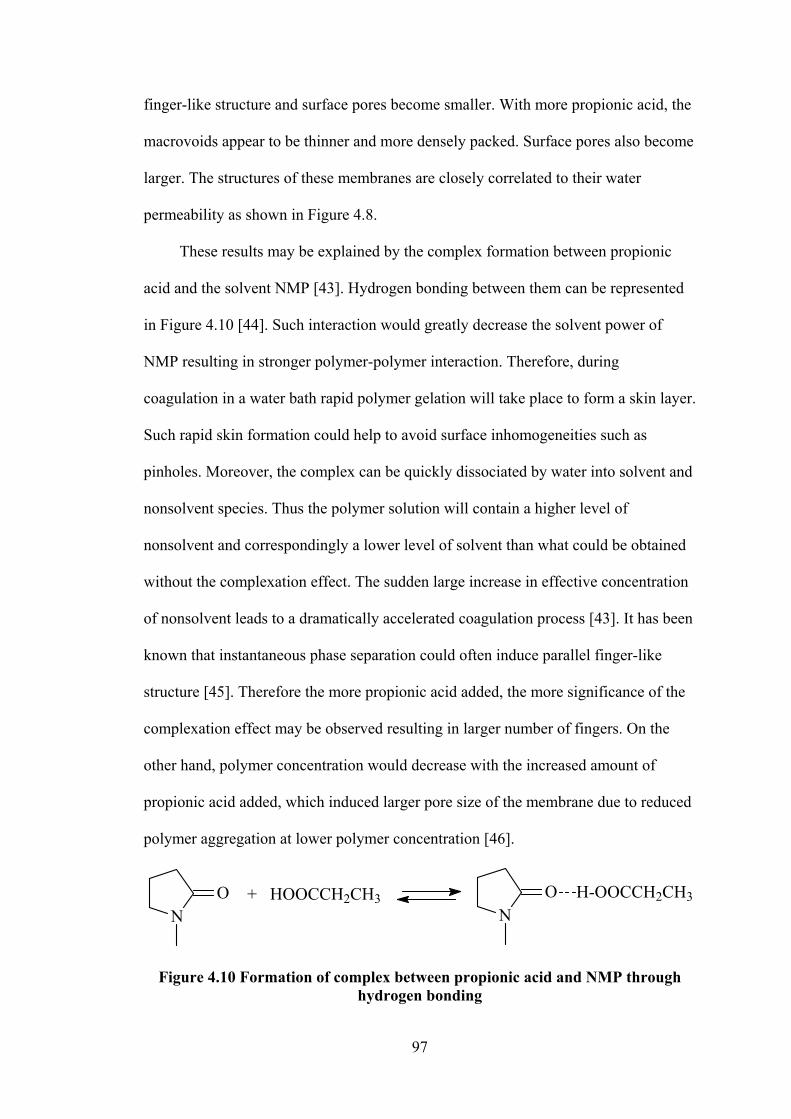
97
finger-like structure and surface pores become smaller. With more propionic acid, the
macrovoids appear to be thinner and more densely packed. Surface pores also become
larger. The structures of these membranes are closely correlated to their water
permeability as shown in Figure 4.8.
These results may be explained by the complex formation between propionic
acid and the solvent NMP [43]. Hydrogen bonding between them can be represented
in Figure 4.10 [44]. Such interaction would greatly decrease the solvent power of
NMP resulting in stronger polymer-polymer interaction. Therefore, during
coagulation in a water bath rapid polymer gelation will take place to form a skin layer.
Such rapid skin formation could help to avoid surface inhomogeneities such as
pinholes. Moreover, the complex can be quickly dissociated by water into solvent and
nonsolvent species. Thus the polymer solution will contain a higher level of
nonsolvent and correspondingly a lower level of solvent than what could be obtained
without the complexation effect. The sudden large increase in effective concentration
of nonsolvent leads to a dramatically accelerated coagulation process [43]. It has been
known that instantaneous phase separation could often induce parallel finger-like
structure [45]. Therefore the more propionic acid added, the more significance of the
complexation effect may be observed resulting in larger number of fingers. On the
other hand, polymer concentration would decrease with the increased amount of
propionic acid added, which induced larger pore size of the membrane due to reduced
polymer aggregation at lower polymer concentration [46].
NO + HOOCCH2CH3
NO H-OOCCH2CH3
Figure 4.10 Formation of complex between propionic acid and NMP through hydrogen bonding

98
4.3.2.2 Preparation and characterization of PEI modified polyimide (PI-PEI) NF membranes
Figure 4.7 (ii) shows the chemical reaction between PMDA-ODA polyimide and
PEI. It can be seen that the resultant PI-PEI NF membrane has a fully cross-linked
structure and contains ether, amide, amine, ammonium and phenyl groups on the
surface. Such chemical characteristics make the membrane positively charged and
rather hydrophilic. This positive charge permits the adsorption of a layer of negatively
charged polyelectrolyte (SPEEK) to prepare a near neutrally charged NF membrane
due to charge compensation.
0 10 20 30 40 50 60 70 80 90 1000
10
20
30
40
50
60
70
80
90
100
NaCl Galactose
0.0
0.5
1.0
1.5
2.0
2.5
3.0
3.5
Pur
e w
ater
per
mea
bilit
y (m
3 m-2da
y-1)
Reation time (min)
Rej
ectio
n to
NaC
l and
Gal
acto
se (%
)
Figure 4.11 Effect of reaction time of polyimide membranes with PEI on the
water permeability, NaCl rejection and galactose rejection performance of the PI-20% membrane sample.
Figure 4.11 shows the effect of reaction time on the water permeability, NaCl
rejection and galactose rejection performance of the PI-20% membrane. With
increasing modification time, water flux decreased gradually and finally reached a
stable value after 1 h. Meanwhile, both galactose rejection and salt rejection increased

99
until a maximum value was reached. The rejection of galactose may be determined
primarily by the surface pore size of the membrane while the rejection of salt may be
determined by both the surface pore size and surface charge of the membrane [1].
Therefore, these results indicate that both surface pore size and surface chemistry
became stable with 1 h modification. The optimum separation performance of the
obtained membrane would be 67.9% NaCl rejection and 93% galactose rejection with
a 1.1 m3m-2day-1 water flux.
Table 4.3 Desalination performance of the various membranes Samples Flux (m3m-2day-1) Rejection (%) PI-10% 0.5 78 PI-40% 1.6 48.6 PI-60% 2.9 25.7
Prepared under the same modification and test conditions, the other three PI
membranes demonstrated a trade-off trend between salt rejection and permeation flux
(Table 4.3). For each membrane, surface chemistry should be the same after
modification. However, their surface pore size may maintain the same order as the
initial PI membranes assuming that same amount of PEI was anchored onto the pore
wall. Larger pores would allow faster mass transport and consequently lower salt
retention and vice versa. We selected the PI-20% membrane for further studies
because both the salt rejection and permeate flux were reasonably high.
Figure 4.12 shows the change in static contact angles of the PEI modified
polyimide membranes in dependence on the modification time. The initial membrane
(PI-20%) was relatively hydrophobic with a contact angle of 75 ± 8°. With increasing
reaction time contact angle was observed to decrease gradually and finally reach a
stable value of 59 ± 4° after 1 h. This considerable decrease of contact angle suggests
that membrane hydrophilicity was improved by introducing hydrophilic functional
groups like amines and ammonium onto membrane surface. These results are in good

100
agreement with the desalination data, confirming that highest modification degree was
reached within 1 h to give a fully modified PI-PEI membrane. Surprisingly, the 30
min modified membrane showed a contact angle of 48 ± 4°, lower than that of the
membrane with longer modification time. It is likely that at 30 min, the large PEI
molecules could only partly bond to the membrane surface. The nonbonding parts of
PEI may cover the membrane surface so that contact angle became very low due to
the hydrophilic amine groups.
0 10 20 30 40 50 60 70 80 900
10
20
30
40
50
60
70
80
90
C
onta
ct a
ngle
(deg
ree)
Reaction time (min)
Figure 4.12 Contact angle of the PEI modified polyimide membranes in dependence on the modification time.
Figure 4.13 shows the rejection to various salts as a function of the feed
concentration for the PEI modified polyimide membranes. A rejection sequence of
CaCl2 > MgSO4 > NaCl > Na2SO4 indicates a positive charge for the membrane [33].
Additionally, the decrease in salt rejection with increasing salt concentration is
consistent with the Donnan exclusion model. As ionic strength increases the

101
membrane charge is shielded, resulting in a lower effective charge and consequently
lower salt rejection [1].
0 50 100 150 2000
10
20
30
40
50
60
70
80
90
100
Concentration (mmol/L)
Salt
reje
ctio
n (%
)
NaCl Na2SO4
CaCl2 MgSO4
Figure 4.13 Rejection to various salts as a function of the feed concentration for
the PEI modified polyimide membranes.
4.3.2.3 Preparation and characterization of SPEEK-coated PI-PEI NF membranes
SPEEK is a negatively charged polyelectrolyte which can be adsorbed firmly
onto the positively charged PI-PEI membranes due to electrostatic attractions. During
coating process, a pressure of 13.8 bar was applied to pass a vigorously stirred
SPEEK solution through the PI-PEI membrane. It has been shown that pressure may
compact the coating film and make it uniform and free of defects [58]. A low
concentration of 0.3 g/L was used in order to control the film thickness and make the
membrane charge nearly neutral [35]. If a high concentration of several grams per
liter was used, excessive material may deposit on the membrane resulting in
membrane charge overbalanced [47]. In addition, a short adsorption time of 10 min
was used as referred to the optimum preparation conditions of PVS coating (see

102
section 4.3.1.2). The resultant PI-PEI/SPEEK NF membranes showed a pure water
flux of about 1 m3m-2day-1 when tested at room temperature and 13.8 bar.
0 50 100 150 2000
10
20
30
40
50
60
70
80
90
100
Concentration (mmol/L)
Salt
reje
ctio
n (%
)
NaCl Na2SO4
CaCl2 MgSO4
Figure 4.14 Rejection to various salts as a function of the feed concentration for the SPEEK-coated PI-PEI NF membranes.
The PI-PEI/SPEEK NF membrane was measured with regard to its rejection to
four charged solutes CaCl2, MgSO4, NaCl, and Na2SO4. The results are shown in
Figure 4.14. Within the concentration range between 10 and 200 mmol/L, a similar
rejection value to CaCl2, MgSO4, and Na2SO4 can be observed to be around 95%. The
rejection to NaCl was around 80%, lower than the other three salts. Therefore, this
membrane could remove multivalent ions, both cations and anions, more efficiently
than monovalent ions. This cannot be explained by Donnan exclusion. It is probable
that the negative charge of SPEEK balanced the positive charge of the P84-PEI
membrane resulting in a slightly negative surface layer. The overall membrane charge
then became almost neutral and the Donnan exclusion effect did not govern the ion

103
separation behavior. Instead, the hydrated diameter of each ion and the diffusion
coefficient of each salt determined the different retentions [1, 48].
4.3.2.4 Characterization of membranes at different preparation stages
Figure 4.15 shows the ATR-FTIR spectra of membranes at different preparation
stages. The PMDA/ODA polyimide (PI) membrane exhibits several characteristic
bands as follows: 1778 cm-1 (symmetric C=O stretching, imide I), 1722 cm-1
(asymmetric C=O stretching, imide I), and 1378 cm-1 (C-N-C stretching, imide II).
The peaks at 1500 cm-1 and 1245 cm-1 are from the C-C stretching of benzene ring
and the C-O-C stretching of ODA, respectively [49]. On the other hand, the typical
polyamic acid absorption bands at 1660 cm-1 (C=O stretching, amide I) and 1550 cm-1
(C-N stretching, amide II) [50], and typical isoimide bands at 1800 cm-1 [51] are
4000 3500 3000 2500 2000 1500 1000
Abs
orpt
ion
Wavenumber (cm-1)
PI
PI-PEI
PI-PEI/SPEEK
amines, N-H
O-H
imide I C=O
benzene ring in PIimide II C-N
C-O
amide I C=Oamide II C-N
C=O in SPEEK
Benzene ring in SPEEK
SO3
-
Figure 4.15 ATR-FTIR spectra of membranes at different preparation stages.

104
totally absent. Therefore, this membrane has an identical infrared spectrum to the
polyimide film cured by thermal process [49, 50, 51], indicating the polyamic acid
was completely transformed to polyimide under these reaction conditions.
After reaction with PEI, the absorption peaks of the imide I bands almost
disappeared. Meanwhile, the characteristic peaks of amide groups at 1644 cm-1 (C=O
stretching, amide I) and 1547 cm-1 (C-N stretching, amide II) appeared [52]. The band
at 3267 cm-1 (N-H vibrations) indicates the existence of free amine groups. From the
FTIR data, one can conclude that within 1 h of reaction, the imide bonds were
completely transformed into amide bonds, resulting in the amine modifier covalently
bound to the PI membrane with free amine functionalities.
When SPEEK was coated, a few new absorption peaks of SPEEK clearly
appeared at 1600 cm-1 (C=O stretching), 1472 cm-1 (phenyl ring), 1084 cm-1
(symmetric O=S=O), 1027 cm-1 (S=O stretching) and 3450 cm-1 (O-H), indicating
SPEEK was successfully deposited on the membrane surface.
Figure 4.16 SEM spectra of the PI-PEI and the PI-PEI/SPEEK NF membranes.
Figure 4.16 shows SEM morphology of the PI-PEI and the PI-PEI/SPEEK NF
membranes. No pore could be observed on the surface of these two membranes. The
PI-PEI membrane looks a little rough while the PI-PEI/SPEEK membrane is very

105
smooth which could be attributed to the preparation method. This smooth surface is
beneficial for fouling resistance.
4.3.2.5 Antifouling property of the PI-PEI/SPEEK membrane in comparison with the PI-PEI and NTR-7450 membranes
Three NF membranes PI-PEI, PI-PEI/SPEEK and commercial NTR-7450 were
used as representative of positively charged, near neutrally charged and negatively
charged membranes respectively. The NTR-7450 membrane was selected because it
has similar sulfonated surface with the PI-PEI/SPEEK membrane. However, The
NTR-7450 membrane has higher permeability than the PI-PEI/SPEEK membrane.
Therefore, a lower pressure of 10.3 bar (150 psi) was used for NTR-7450 while a
pressure of 13.8 bar was used for both the PI-PEI and the PI-PEI/SPEEK membranes
which resulted in similar water fluxes for three of them. It has been shown that the
initial flux, rather than applied pressure, seems to directly affect the extent of flux
reduction [53]. With similar initial fluxes and the same other experimental conditions,
the difference in degree of flux decline during fouling tests may reflect different
fouling resistance of these membrane with different surface charging. Their fouling
resistance was measured in dead-end mode using three model foulants of BSA, HA
and SA as representative of proteins, NOM and polysaccharides, respectively.
Figure 4.17 shows flux decline during dead-end filtration of a feed solution
containing 1% (w/v) BSA in 0.01 M PBS. For each membrane, the water flux at any
given time was normalized to the initial stabilized flux after compaction. The initial
fluxes for each membrane are shown in the legend. For all the membranes, fluxes
decreased with the increase of filtration time. The flux decline may be caused by both
membrane fouling and concentration of the feed solution due to the high retention of
the solutes. In order to remove the concentration effect, at certain filtration time (90

106
min or 120 min), the permeate was refilled into the feed to restore the initial feed
concentration. Then the flux would be restored to a higher value which may be caused
primarily by the fouling effect. By this definition, the PI-PEI/SPEEK membrane had
very little fouling since the flux was almost fully recovered after feed refill. Both the
PI-PEI and the NTR-7450 membranes showed similar flux profile. The foulant-
caused flux decline of these was much more than that of the PI-PEI/SPEEK
membrane. These results suggest that the neutrally charged membrane has much
better fouling resistance than both the positively charged and the negatively charged
membranes. Although the overall charge of BSA is close to neutral, it has a variety of
functional groups including amines and carboxylic acid, which provide both positive
sites and negative sites respectively. It is likely that these charged sites could be
adsorbed on an oppositely charged surface via electrostatic interactions. However, for
a membrane with a low surface charge, such electrostatic interaction could be
minimized resulting in very little BSA adsorption.
0 30 60 90 120 150 180 210 240 270 3000.0
0.1
0.2
0.3
0.4
0.5
0.6
0.7
0.8
0.9
1.0
1.1
Neutrally charged membrane: PI-PEI/SPEEK, J0 = 0.95 m
3m
-2day
-1
Positively charged membrane: PI-PEI, J0 = 1.05 m
3m
-2day
-1
Negatively charged membrane: NTR 7450, J0 = 1.10 m
3m
-2day
-1
Time (min)
Nor
mal
ized
flux
(J/J
0)
Figure 4.17 Dead-end filtration of model protein solution (bovine serum albumin,
1.0 g/L, 13.8 bar) with PI-PEI, PI-PEI/SPEEK and NTR-7450

107
0 30 60 90 120 150 180 210 240 270 3000.0
0.1
0.2
0.3
0.4
0.5
0.6
0.7
0.8
0.9
1.0
1.1
Nor
mal
ized
flux
(J/J
0)
Time (min)
Neutrally charged membrane: PI-PEI/SPEEK, 250 psi, J0 = 1.00 m
3m
-2day
-1
Positively charged membrane: PI-PEI, 250 psi, J0 = 1.44 m
3m
-2day
-1
Negatively charged membrane: NTR 7450, 150 psi, J0 = 0.96 m
3m
-2day
-1
Figure 4.18 Dead-end filtration of model NOM solution (humic acid, 1.0 g/L, 1
mM CaCl2, 13.8 bar) with PI-PEI, PI-PEI/SPEEK and NTR-7450
0 30 60 90 120 150 180 210 240 270 3000.0
0.1
0.2
0.3
0.4
0.5
0.6
0.7
0.8
0.9
1.0
1.1
Time (min)
Nor
mal
ized
flux
(J/J
0)
Neutrally charged membrane: PI-PEI/SPEEK, J0 = 1.12 m
3m
-2day
-1
Positively charged membrane: PI-PEI, J0 = 1.40 m
3m
-2day
-1
Negatively charged membrane: NTR 7450, J0 = 0.94 m
3m
-2day
-1
Figure 4.19 Dead-end filtration of model polysaccharide solution (sodium
alginate, 1.0 g/L, 13.8 bar) with PI-PEI, PI-PEI/SPEEK and NTR-7450

108
Flux decline caused by 1.0 g/L HA or 1.0 g/L SA is shown in Figure 4.18 and
Figure 4.19 respectively. The HA solution also contains 1mM CaCl2 to enhance
fouling tendency of humic acid because Ca2+ ions can bridge the carboxyl groups of
humic acid. Both figures show the same sequence of flux decline: PI-PEI/SPEEK <
NTR-7450 < PI-PEI indicating the fouling resistance of the three membranes has a
reversed order. Both the HA and SA contain a lot of carboxylic groups and thus are
negatively charged. As expected, the positively charged membrane could adsorb the
oppositely charged foulants due to charge attractions giving the highest flux decline.
Although a negatively charged membrane could repulse negatively charged small
molecules like surfactants, it may not be true for large complicated polymers like HA
and SA. Similar to BSA, HA and SA may also have some positive sites. The charge
interaction with a negative surface could be stronger than that with a neutral surface.
Therefore, the neutral membrane would show the lowest foulant adsorption by
eliminating any charge related interactions.
4.3.3 Resistance to activated sludge of the PI-PEI/SPEEK and the P84-PEI/PVS membranes in comparison with the NTR-7450 membrane
The results from above studies suggest that the newly designed NF membranes
by coating a layer of negatively charged polyelectrolytes onto the surface of positively
charged NF membranes should exhibit lower fouling and produce higher quality
effluents in MBR operations compared with UF membranes conventionally
employed. For potential MBR application, fouling tendency of three membranes, PI-
PEI/SPEEK, P84-PEI/PVS and commercial NTR-7450 was preliminarily investigated
in dead-end mode using activated sludge taken from an aerobic bioreactor. Figure
4.20 compares the normalized flux data for the three NF membranes. The PI-
PEI/SPEEK membrane showed less flux decline for the entire time range and
correspondingly better resistance to activated sludge than the NTR-7450 membrane.

109
However, the P84-PEI/PVS membrane showed much worse resistance to activated
sludge than both the PI-PEI/SPEEK and the NTR-7450. This surprising result may be
related to other surface characteristics such as hydrophilicity, surface roughness and
pore structure. Since the activated sludge may consist of complicated components
including salts, organics, colloidal and particles, further detailed studies are required
to characterize and modify the membrane surface properties for use in MBR
application.
0 30 60 90 120 150 180 210 240 270 3000.0
0.1
0.2
0.3
0.4
0.5
0.6
0.7
0.8
0.9
1.0
1.1
Time (min)
Nor
mal
ized
flux
(J/J
0)
PI-PEI/sPEEK, J0 = 0.99 m3m-2day-1
NTR-7450, J0 = 1.20 m3m-2day-1
P84-PEI/PVS, J0 = 1.24 m3m-2day-1
Figure 4.20 Dead-end filtration of model activate sludge solution (MLSS: 3000 –
4300 mg/L, 13.8 bar) with PI-PEI/SPEEK, NTR-7450 and P84-PEI/PVS
4.4 Conclusions
In order to prepare a fouling resistant NF membrane for potential MBR
application, we designed two kinds of membrane systems. The first system consisted
of a partially modified P84 polyimide membrane with PEI and a surface coating using
PVS or PVA. By decreasing the extent of chemical modification which was carried

110
out at a low reaction temperature and controlled time, membrane brittleness was
improved due to the decreased degree of cross-linking. Several initial P84 membranes
were prepared from casting solutions with various concentrations from 19% to 25%.
Their pore size and water permeability varied considerably. After modification with
PEI and coating with PVS or PVA, the final membranes showed properties in a broad
range between loose ultrafiltration to nanofiltration. These membranes may meet the
needs in various industrial applications such as MBR.
Another system involved preparation of a nearly neutrally charged NF membrane
developed by adsorption of a layer of negatively charged SPEEK onto the surface of a
positively charged NF membrane. Still, the positively charged NF membranes were
prepared by chemical modification of PMDA-ODA polyimide membranes using PEI.
The modified PI-PEI membrane showed a rejection sequence of CaCl2 > MgSO4 >
NaCl > Na2SO4, which could be explained by Donnan repulsion effect. After coating
SPEEK, the PI-PEI/SPEEK membrane could remove multivalent ions more
efficiently (> 95%) than monovalent ions (80%) due to the size effect; a rejection
sequence of CaCl2 ≈ MgSO4 ≈ Na2SO4> NaCl was observed. When using bovine
serum albumin (BSA), humic acid and sodium alginate as the model foulants, the
neutrally charged membrane exhibited much better fouling resistance than both the
positively charged and negatively charged membranes. This result suggests that the
foulants would be less likely to deposit onto a neutral membrane due to the
elimination of the charge interaction between the membrane and the foulants.
In an attempt to apply these two systems in an MBR process, it was found that
the second membrane system PI-PEI/SPEEK showed much better resistance to
activated sludge than the first membrane system P84-PEI/PVS. Although these two
membranes had similar surface chemistry and surface charging, they may have other

111
differences in surface properties such as hydrophilicity, roughness and pore structure,
which needs further detailed studies in the future.
4.5 References [1] A.I. Schäfer, A.G. Fane, T.D. Waite (Eds.), Nanofiltration - Principles and
Applications, Elsevier Ltd., 2005.
[2] R.W. Baker (Ed.), Membrane technology and applications, John Wiley & Sons, Ltd., Chichester, 2004.
[3] Bailey, B.; Lamsal, R.; Farzana, N.; Walsh, M. E.; Gagnon, G. A. Water reclamation and reuse. Water Environment Research 80(10) (2008) 1281.
[4] R.J. Petersen, Composite reverse osmosis and nanofiltration membranes, J. Membr. Sci., 83 (1993) 81.
[5] Pabby, A. K.; Rizvi, S. S. H.; Sastre, A. M. Membrane bioreactors for wastewater treatment in Handbook of Membrane Separations Casey, E., Eds 2009, 1007.
[6] K. Kimura, Y. Hane, Y. Watanabe, G. Amy, N. Ohkuma, Irreversible membrane fouling during ultrafiltration of surface water, Water Research 38 (14-15) (2004) 3431.
[7] M.F.A. Goosen, S.S. Sablani, H. Al-Hinai, S. Al-Obeidani, R. Al-Belushi, D. Jackson, Fouling of reverse osmosis and ultrafiltration membranes: A critical review, Sep. Sci. Technol. 39 (10) (2004) 2261.
[8] N. Hilal, O.O. Ogunbiyi, N.J. Miles, R. Nigmatullin, Methods employed for control of fouling in MF and UF membranes: a comprehensive review, Sep. Sci. Technol. 40 (2005) 1957.
[9] A. Bhattacharya, P. Ghosh, Nanofiltration and reverse osmosis membranes: Theory and application in separation of electrolytes, Reviews in chemical Engineering, 20 (2004) 111.
[10] M. Elimelech, X. Zhu, A.E. Childress, S. Hong, Role of membrane surface morphology in colloidal fouling of cellulose acetate and composite aromatic polyamide reverse osmosis membranes, J. Membr. Sci. 127 (1997) 101.
[11] X. Zhu, M. Elimelech, Colloidal fouling of reverse osmosis membranes: measurements and fouling mechanisms, Environ. Sci. Technol. 31 (1997) 3654.
[12] E.M. Vrijenhoek, S. Hong, M. Elimelech, Influence of membrane surface properties on initial rate of colloidal fouling of reverse osmosis and nanofiltration membranes, J. Membr. Sci. 188 (2001) 115.
[13] E.M.V. Hoek, S. Bhattacharjee, M. Elimelech, Effect of membrane surface roughness on colloid-membrane DLVO interactions, Langmuir 19 (2003) 4836.
[14] C.R. Reiss, J.S. Taylor, C. Robert, Surface water treatment using nanofiltration --pilot testing results and design considerations, Desalination 125 (1999) 97.

112
[15] M. Kabsch-Korbutowicz, K. Majewska-Nowak, T. Winnicki, Analysis of
membrane fouling in the treatment of water solutions containing humic acids and mineral salts, Desalination 126 (1999) 179.
[16] A.G. Fane, C.J.D. Fell, A review of fouling and fouling control in ultrafiltration, Desalination 62 (1987) 117.
[17] P.J. Evans, M.R. Bird, A. Pihlajamäki, M. Nyström, The influence of hydrophobicity, roughness and charge upon ultrafiltration membranes for black tea liquor clarification, J. Membr. Sci. 313 (2008) 250.
[18] A. Weis, M.R. Bird, M. Nyström, C. Wright, The influence of morphology, hydrophobicity and charge upon the long-term performance of ultrafiltration membranes fouled with spent sulphite liquor, Desalination 175 (2005) 73.
[19] B. Van der Bruggen, M. Mänttäri, M. Nyström, Drawbacks of applying nanofiltration and how to avoid them: A review, Sep. Purif. Technol. 63 (2008) 251.
[20] M. Mänttäri, L. Puro, J. Nuortila-Jokinen, M. Nyström, Fouling effects of polysaccharides and humic acid in nanofiltration, J. Membr. Sci. 165 (2000) 1.
[21] A. Al-Amoudi, R.W. Lovitt, Fouling strategies and the cleaning system of NF membranes and factors affecting cleaning efficiency, J. Membr. Sci. 303 (2007) 4.
[22] J. Gilron, S. Belfer, P. Väisänen, M. Nyström, Effects of surface modification on antifouling and performance properties of reverse osmosis membranes, Desalination 140 (2001) 167.
[23] I. Pinnau, J.H. Ly, R.W. Baker, Reverse osmosis membrane and process, US patent 7,490,725 B2 (2009).
[24] C. Bartels, M. Wilf, W. Casey, J. Campbell, New generation of low fouling nanofiltration membranes, Desalination 221 (2008) 158.
[25] J.-H. Choi, K. Fukushi, K. Yamamoto, Comparison of treatment efficiency of submerged nanofiltration membrane bioreactors using cellulose triacetate and polyamide membrane, Water Science & Technology 51 (2005) 305.
[26] J.-H. Choi, K. Fukushi, K. Yamamoto, A submerged nanofiltration membrane bioreactor for domestic wastewater treatment: the performance of cellulose acetate nanofiltration membranes for long-term operation, Sep. Purif. Technol., 52 (2007) 470.
[27] S. Liang, Y. Zhao, C. Liu, L. Song, Effect of solution chemistry on the fouling potential of dissolved organic matter in membrane bioreactor systems, J. Membr. Sci., 310 (2008) 503.
[28] R. Valadez-Blanco, F.C. Ferreira, R.F. Jorge, A.G. Livingston, A membrane bioreactor for biotransformations of hydrophobic molecules using organic solvent nanofiltration (OSN) membranes, J. Membr. Sci., 317 (2008) 50.
[29] B.N. Tsai, C.H. Chang, D.J. Lee, J.Y. Lai, Fractionation of organic matters in sludge rejected by NF membrane, Desalination, 234 (2008) 386.
[30] P. Le-Clech, V. Chen, A.G. Fane, Fouling in membrane bioreactors used in wastewater treatment, J. Membr. Sci., 284 (2006) 17.

113
[31] S. Judd (Editor), The MBR Book: Principles and Applications of Membrane
Bioreactors for Water and Wastewater Treatment, Elsevier Ltd., 2006.
[32] F. Meng, S.-R. Chae, A. Drews, M. Kraume, H.-S. Shin, F. Yang, Recent advances in membrane bioreactors (MBRs): Membrane fouling and membrane material, Water Research, 43 (2009) 1489.
[33] C. Ba, J. Langer, J. Economy, Chemical modification of P84 copolyimide membranes by polyethylenimine for nanofiltration, J. Membrane Sci. (2009), 327(1-2), 49.
[34] J. Economy, J. Wang, C. Ba, Design of advanced membranes and substrates for water purification and desalination, Nanotechnology Applications for Clean Water, D. Mamadou, J. S. Duncan, N. Savage, A. Street, R. C. Sustich (Eds.), Elsevier Ltd., 2008.
[35] C. Ba, D.A. Ladner, J. Economy, Using protective polyelectrolyte films to improve fouling resistance of a positively charged NF membrane, J. Membr. Sci. 347 (2010) 250.
[36] W. Yuan, A.L. Zydney, Humic acid fouling during microfiltration, J. Membr. Sci. 157 (1999) 1.
[37] J. Wang, Y. Yao, Z. Yue, J. Economy, Preparation of polyelectrolyte multilayer films consisting of sulfonated poly(ether ether ketone) alternating with selected anionic layers, J. Membr. Sci. 337 (2009) 200.
[38] A. Lui, F.D.F. Talbot, A. Fouda, T. Matsuura and S. Sourirajan, Studies on the solvent exchange technique for making dry cellulose acetate membranes for the separation of gaseous mixtures, J. Appl. Polym. Sci. 36 (1988) 1809.
[39] B.V.d. Bruggen, J. Schaep, D. Wilms, C. Vandecasteele, Influence of molecular size, polarity and charge on the retention of organic molecules by nanofiltration, J. Membr. Sci. 156 (1999) 29.
[40] M. Dubois, K.A. Gilles, J.K. Hamilton, P.A. Rebers, F. Smith, Colorimetric method for determination of sugars and related substances, Anal. Chem. 28 (1956) 350.
[41] K. Boussu, C. Vandecasteele, B. Van der Bruggen, Study of the characteristics and the performance of self-made nanoporous polyethersulfone membranes, Polymer, 47 (2006) 3464.
[42] C. Ba, J. Economy, Preparation of polyimide for use as substrate in a thermally stable composite membrane, J. Membr. Sci. Submitted.
[43] H. Ohya, V.V. Kudryavtsev, S.I. Semenova, Polyimide Membranes: Applications, Fabrications, and Properties, Gordon and Breach, Tokyo, 1996.
[44] R.E. Kesting, A.K. Fritzsche, M.K. Murphy, A.C. Handermann, C.A. Cruse, R.F. Malon, U.S. Pat. 4,880,441, 1989.
[45] M. Mulder, Basic Principles of Membrane Technology, Kluwer, London, 1996.

114
[46] K. Boussu, C. Vandecasteele, B. Van der Bruggen, Study of the characteristics
and the performance of self-made nanoporous polyethersulfone membranes, Polymer, 47 (2006) 3464.
[47] L. Ouyang, R. Malaisamy, M.L. Bruening, Multilayer polyelectrolyte films as nanofiltration membranes for separating monovalent and divalent cations, J. Membr. Sci. 310 (2008) 76.
[48] J.M.M. Peeters, J.P. Boom, M.H.V. Mulder, H. Strathmann, Retention measurements of nanofiltration membranes with electrolyte solutions, J. Membr. Sci. 145 (1998) 199.
[49] K.H. Yu, Y.H. Yoo, J.M. Rhee, M.-H. Lee, S.-C. Yu, Synthesis of poly[(amic acid)-co-(amic ester)] precursors and studies of their imidization using FT-IR and FT-Raman spectroscopy, Mat. Res. Innovat. 7 (2003) 51.
[50] J. Yang, M.-H. Lee, A water-soluble polyimide precursor: synthesis and characterization of poly(amic acid) salt, Macromol. Res. 12 (2004) 263.
[51] Y. J. Kimt, J.S. Kim, K.-Y. Choi, Studies of the formation of polyisoimides and their imidization in solution state, J. Ind. Eng. Chem. 7 (2001) 400.
[52] X. Qiao, T.-S. Chung, Diamine modification of P84 polyimide membranes for pervaporation dehydration of isopropanol, AIChE, 52 (2006) 3462.
[53] C.Y. Tang, Y.-N. Kwon, J.O. Leckie, Fouling of reverse osmosis and nanofiltration membranes by humic acid – Effects of solution composition and hydrodynamic conditions, J. Membr. Sci. 290 (2007) 86.

115
CHAPTER 5
PREPARATION OF PMDA-ODA POLYIMIDE MEMBRANE FOR USE AS SUBSTRATE IN A THERMALLY STABLE COMPOSITE MEMBRANE
5.1 Introduction
Today, thin-film-composite (TFC) membranes, prepared by coating a very thin
layer of aromatic polyamide onto a polysulfone substrate, are well accepted for water
desalination because of their high rejection rate and high water permeability [1].
However, it is still a challenge to develop chemically and thermally stable polymeric
membranes which can withstand harsh environments including pH extremes, oxidants
like chlorine, organic solvents, and very low or high temperatures, etc. while
maintaining or even enhancing the separation capacity of the commercial TFC
membranes [1, 2]. Such membranes are highly desired for many industrial processes.
For example, in the sugar industry, a temperature of around 95 ˚C is desired to avoid
repeated cooling and heating in the sugar production process, and to reduce microbial
growth [3]. The pulp and paper industry also needs membranes which can resist high
temperatures of 70 - 90 ˚C and alkaline conditions [3]. Therefore it is of interest to
develop thermally stable membranes to overcome the limitation of 45 ˚C for the
commercial membranes [4, 5, 6, 7]. For this purpose, high performance polymers like
polyimides (PIs) may be considered for developing a new generation of membranes
for water purification and desalination [8].
Due to their unique properties, polyimides have been developed into
membranes for separation of gases, vapors and liquids [9]. Polyimide membranes
exhibit excellent resistance to almost all chemical agents. Their thermal resistance

116
allows separations to be performed for a long time at elevated temperatures [10].
Specifically, poly(pyromellitic dianhydride-co-4,4’-oxydianiline) (PMDA/ODA PI)
has a very high glass transition temperature of approximately 400 ˚C and excellent
resistance to most non-oxidizing acids at room temperature and almost all organic
solvents [11]. However, because the PMDA/ODA PI is both insoluble and infusible,
any products, including membranes, can only be processed from its precursor,
polyamic acid (PAA), which requires an additional step to transform the PAA into PI
by either thermal or chemical treatments. So far, studies have focused on its
fabrication into symmetric membranes or composite membranes for separation of
gases and organics [8, 12, 13, 14, 15]. A dense symmetric membrane, prepared from
PAA solution via solvent evaporation followed by chemical imidization, has also been
applied for water desalination. Although the salt rejection was high, the water flux
was very low [16].
There are several problems with developing PMDA/ODA PI asymmetric
membranes from PAA using the phase inversion method. Firstly, because of the
hydrophilic carboxylic groups, PAA has strong interaction with water, which makes
the phase inversion slow. The resultant PAA membranes usually contain large
amounts of macrovoids, which make the membranes mechanically very weak [17].
Secondly, PAA is known to be thermally unstable even at room temperature and tends
to hydrolysis with water [18]. Thirdly, when transforming the PAA into PI by the
thermal process, the pores of the membranes tend to collapse, which results in a
shrinking of the PI membranes. Consequently, dense membranes are obtained with

117
very low permeability [19]. To solve these problems, several approaches have been
reported to modify the PAA to decrease its hydrophilicity and improve its hydrolytic
stability as well. For example, partially imidized PAA was used for membrane
development and the effect of PAA imidization on solution characteristics and
membrane morphology was studied [20]. With a benzimidazole additive, the
carboxylic groups of PAA were blocked so as to decrease the hydrophilicity of PAA
[19]. PAA amine salts, prepared by reaction with tertiary amines like triethylamine,
have shown improved hydrolytic stability [21]. However, the PAA amine salt
polymers are soluble in water and thus may not be suitable for developing asymmetric
membranes by the phase inversion method. In order to prevent membrane shrinking
during the thermal imidization process, a chemical process using acetic anhydride as
dehydration agent and triethylamine as catalyst provides an alternative option [9].
Because of their strong coordination with the transition metal ions, the
carboxylic groups of PAA can be neutralized by cations, such as Zn2+, Ni2+ and Cu2+,
to form ionomers. These divalent cations may act as cross-linkers so that these
ionomers behave as thermoplastic elastomers [22]. Immersion of PAA films or fibers
into aqueous solutions of transition metal salts leads to chelation of a certain amount
of metals onto the PAA, confirming the strong interaction between the PAA and the
metal ions [23]. The improvements in physical properties and chemical stability after
coordination with metal ions may benefit the development of asymmetric
PMDA/ODA PI membranes. To the best of our knowledge, no related studies have
been reported on preparation of PI membranes using this method.

118
In this study, we added predetermined amounts of zinc chloride (ZnCl2) into a
PAA solution to modulate the physical properties of the casting dope. We selected
ZnCl2 instead of zinc acetate (ZnAc2) as an additive because ZnCl2 could be readily
dissolved in PAA/NMP solution while even small amounts of ZnAc2 would
precipitate the polymer. The change in viscosity of the polymer solution was
measured with increasing amounts of the ZnCl2 added. Then the ZnCl2-containing
casting dope was cast onto a polyester support followed by immersing into a water
bath to prepare an asymmetric porous PAA membrane. The effect of ZnCl2 on the
morphology of PI membrane was then investigated. By chemical imidization, the
PAA membrane was transformed into PI membrane which could then be used as
substrate for depositing a thin layer of cross-linked aromatic polyamide by interfacial
polymerization. This composite membrane could be used for water desalination with
much better thermal stability than the commercial composite membranes based on
polysulfone substrate.
5.2 Experimental
5.2.1 Chemicals
Poly(pyromellitic dianhydride-co-4,4’-oxydianiline) amic acid solution (PAA)
was purchased from Aldrich as a 15% solution in N-methyl-2-pyrrolidone (NMP) and
stored in a freezer. Trimesoyl chloride (TMC; Aldrich, 98%) was distilled under
reduced pressure and stored in a desiccator to prevent hydrolysis of the acyl chloride
groups. m-Phenylenediamine (MPDA; Aldrich, ≥ 99%) and anhydrous zinc chloride

119
(ZnCl2; Aldrich, ≥ 98%) were used as received. All the other reagents and solvents
were of analytical grade and used as received.
5.2.2 Preparation of the polyimide membranes
Three casting solutions were prepared by adding 0%, 6% and 24% ZnCl2 into
the 15% PAA/NMP solution. With more than 24% ZnCl2, the polymer solution was
so highly viscous that membrane processing became difficult. The percentage of
added ZnCl2 was based on the polymer solution not on the polymer itself. For
example, to make a casting solution with 6% ZnCl2, 6 g of anhydrous ZnCl2 was
added to 100 g of the 15% PAA/NMP solution. The mixture was then stirred by a
mechanical stirrer until the zinc chloride was totally dissolved. After that, the solution
was degassed under vacuum to remove all the bubbles. The casting solution was then
cast onto a polyester support (Calendered PET from Crane Nonwovens) and
immersed immediately into a water coagulation bath at room temperature. The
membrane thickness was controlled at roughly 100 micron. After 30 min, the
membrane was removed from the water bath and washed thoroughly with deionized
(DI) water. Then the PAA membrane was dried by an isopropanol-hexane
displacement sequence [24]: the membrane was immersed in the isopropanol for 90
min during which the isopropanol was refreshed 3 times. Subsequently, the
isopropanol was replaced by hexane using the same procedure. Chemical imidization
was performed by immersing the PAA membranes into a mixture of acetic anhydride
(Ac2O) and triethylamine (TEA) (volume 4:1) at 100 ˚C for 36 hours, as shown in

120
Scheme 5.1. The resultant PI membranes were then washed using isopropanol several
times and stored in isopropanol.
Scheme 5.1 Synthesis of polyimide from polyamic acid precursor via
chemical treatment.
5.2.3 Preparation of the composite membranes
The composite membranes were prepared by the interfacial polymerization of
MPDA with TMC on the surface of the PI membrane support. The PI membrane was
dipped into an aqueous solution of MPDA. After removing excess liquid on the
membrane surface using soft paper tissues, the membrane was immersed into a
hexane solution of TMC, which resulted in an in-situ formation of a barrier layer over
the surface of the polyimide substrate. The resulting composite membrane was dried
at room temperature in air for two minutes to evaporate hexane and then stored in DI
water prior to characterization. The preparation parameters including the monomer
concentrations, immersion times, and post annealing were evaluated in order to obtain
optimal desalination performance. For each data point, a minimum of two membrane
samples were tested and averaged.
5.2.4 Membrane desalination performance measurements
Desalination performance of the composite membranes was examined using a
dead-end filtration cell (Sterlitech HP4750) and 300 mL of a 2.0 g/L NaCl aqueous
feed solution under 55.2 bar (800 psig). The feed solution was stirred at a rate of 1100
rpm in the cell using a standard magnetic stirrer (Corning Stirrer/Hot Plate, Model

121
PC-420) to minimize concentration polarization. Each membrane was compacted at a
pressure of 55.2 bar for nine hours prior to measurements to ensure a steady state was
obtained. The permeated solution was then refilled into the feed and permeate
samples were collected as appropriate. The permeation flux F was determined by
measuring the permeation volume V (20 mL, 6.7% recovery) flowing across the
membrane of area A (14.6 cm2) in the time period Δt, F (m3m-2day-1) = V/(A × Δt).
The salt rejection was calculated as R = (1 – σp/σf) × 100%, where σp and σf were the
conductivity of the permeate and the feed respectively. The conductivity of the NaCl
solution was measured with a bench-top conductivity meter (Oakton CON 510).
5.2.5 Membrane thermal stability measurements
The thermal stability of the TFC membrane was evaluated by measuring the
change of water flux and salt rejection with temperature increasing from 25 ˚C to 95
˚C under a constant pressure of 27.6 bar (400 psi) and a 2.0 g/L NaCl solution.
Heating of the testing solution was performed by immersing the dead-end filtration
cell in a temperature controlled water bath.
5.2.6 Characterization techniques
The viscosities of the casting solutions containing various amounts of ZnCl2
were measured using an Ubbelohde capillary viscometer in a thermostated water bath
at 29.0 ± 0.1 ˚C. The relative viscosity value of each ZnCl2-containing casting
solution was determined by normalizing its efflux time with respect to that of ZnCl2-
free polymer solution.

122
Characterization of membrane chemistry and morphology was conducted by
attenuated total reflectance Fourier transform infrared spectroscopy (ATR-FTIR), X-
ray photoelectron spectroscopy (XPS), scanning electron microscopy (SEM) and
atomic force microscopy (AFM). All membrane samples were dried using the solvent
exchange method to prevent the porous structure from collapsing upon drying [25].
ATR-FTIR spectra were collected at room temperature over a scanning range of
600 - 4000 cm-1 with a resolution of 4.0 cm-1, using a Nexus 670 FT-IR (Thermo
Electron Corporation, Madison, WI) with a Golden Gate™ MKII Single Reflectance
ATR (Specac Inc., Woodstock, GA). The spectrometer was installed with a deuterated
triglycine sulfate-potassium bromide (DTGS-KBr) detector and KBr beam splitter.
Spectra collection was performed using FT-IR software (OMNIC, Thermo Electron
Corporation, Madison, WI).
XPS experiments were performed on a Physical Electronics PHI Model 5400
surface analysis system using an achromatic Mg Kα (1253.6 eV) X-ray source
operated at 300 W.
SEM images were obtained using a Hitachi S-4700 with 15.0 kV accelerating
voltage. For cross-sectional observations the polyimide layer was peeled off of the
polyester support and fractured after immersion in liquid nitrogen. All samples were
coated by sputtering with gold and palladium before testing.
AFM was performed in air using a Veeco / Digital Instruments Dimension 3100
AFM. Surface roughness of the membranes was obtained by surface image analysis.

123
5.3 Results and discussion
5.3.1 Effect of ZnCl2 additive on viscosities of the casting solutions
Figure 5.1 shows the change of viscosities of the polymer solutions by adding
up to 10% ZnCl2. With more ZnCl2, the solution became too viscous to be measured
by the viscometer. It can be seen that initially the solution viscosity increased linearly
until 6% ZnCl2 was added. With more ZnCl2 from 6% to 10%, the solution viscosity
increased more rapidly. An intersection at 6% can be clearly observed, at which point
the molar ratio of Zn2+ to 2COOH can be calculated to be 1.2, close to equality.
Figure 5.1 Change of viscosities of the PAA solutions by adding ZnCl2. Viscosity was measured using an Ubbelohde Capillary Viscometer in a thermostated water
bath at 29.0 ± 0.1 ˚C.
These results may be explained by the interaction between Zn2+ and both the
polymer PAA [23] and the solvent NMP [26]. Due to the strong coordination

124
interaction between Zn2+ ion and carboxylic groups [27], initially each Zn2+ ion
preferably binds to two PAA carboxylic groups in an intermolecular manner forming
an ionic cross-linking network, as shown in Figure 5.2. The ionic cross-linking would
decrease the mobility of the polymer chains resulting in enhanced viscosity. In
addition, in the presence of zinc ions, the charge of the PAA is reduced due to the
charge screening effect as well as the complex formation. This ionic cross-linking and
charge decrease can reduce the hydrophilicity of the PAA and thus are favorable for
membrane formation. At the point of 6% ZnCl2 added, however, the complexation
reaches a maximum value. With more ZnCl2, a stable complex can be formed
between Zn2+and the NMP, which would reduce the solvating power of NMP for the
polymer and increase the solution viscosity further.
Figure 5.2 Possible intermolecular cross-linking structure formed by the interaction between Zn2+ and polyamic acid.
125
5.3.2 Preparation and characterization of the polyimide substrate membranes
5.3.2.1 Effect of ZnCl2 additive on membrane morphologies
In this study, we prepared three kinds of membranes from polyamic acid
solution containing 0%, 6% and 24% ZnCl2 respectively and then imidized the
polyamic acid into polyimide. These PI membranes will be referred to as PI-0%, PI-
6% and PI-24% membranes. Figure 5.3 presents SEM images of the membrane cross-
sections and surfaces. The PI-0% membrane shows a highly porous structure
containing a large amount of macrovoids. Most of the macrovoids extend deeply to
the bottom of the membrane. Consequently, these macrovoids lead to mechanical
weakness and the membrane easily ruptured in high pressure operations. When 6%
ZnCl2 was added to the casting solution, the macrovoids become smaller showing a
parallel finger-like structure. Meanwhile, a sponge-like structure formed at the
membrane bottom. When the ZnCl2 content in the solution was raised to 24%, the
content of the sponge-like structure increased significantly while the number of the
macrovoids decreased. While the PI-0% membrane contains a lot of micropores on
the surface with the diameter ranging from 10 to 20 nm, at 6% ZnCl2 additive the pore
diameter decreased to 5 - 8 nm, and at 24% ZnCl2 additive no pores were detected.
Therefore, the ZnCl2 additive played an important role to suppress the macrovoid
formation in the membranes, which made the membranes mechanically stronger.
Meanwhile, the membrane surface became less porous after adding ZnCl2 to the
casting solution.

126
Figure 5.3 Cross-sectional (left) and surface (right) morphologies of the polyimide substrate membranes developed from polyamic acid solutions with
different amount of ZnCl2 additive.
Morphological changes of these membranes may be closely related to the
properties of the casting solutions. Before adding ZnCl2, the PAA/NMP solution had
low viscosity. Due to the strong mutual affinity between water and NMP, rapid
solvent/nonsolvent exchange occurred during the quench step. This process, so-called
instantaneous phase separation, can commonly result in membranes having a
microporous skin layer and a finger-like substructure [28, 29]. The addition of 6%

127
ZnCl2 could facilitate polymer precipitation during quenching in water through the
formation of a cross-linked structure as mentioned before. Consequently, the resultant
membrane has a relatively dense surface which can hinder the exchange diffusion
between the solvent and the nonsolvent. This decreased diffusion rate could delay the
phase separation process so that the growth of the macrovoids was suppressed [30].
This effect became more evident when 24% ZnCl2 was added to the casting solution.
The diffusion between the solvent and the nonsolvent became even more difficult due
to the denser membrane surface as a result of very high viscosity of the casting
solution [31]. Similar effects on membrane structure have been observed when using
inorganic salt additives in various polymer-solvent systems [17, 32, 33].
Figure 5.4 AFM images of the surface morphologies of the polyimide substrate membranes developed from polyamic acid solutions with different amount of
ZnCl2 additive. Scanning area: 10 µm×10 µm.
Figure 5.4 shows the three-dimensional AFM images of the three membrane
surfaces. The PI-0%, PI-6% and PI-24% membranes have surface roughness of 68.5
nm, 37.4 nm and 3.4 nm (root mean square RMS roughness), respectively. The
reduction in surface roughness by adding ZnCl2 may be attributed, in part, to the
reduction of the surface pore size as illustrated by SEM. Moreover, it can be seen

128
from Figure 5.3 that there are some spherical protuberances in PI-0% and PI-6%
membrane surfaces, which may also contribute to the membrane roughness. However,
there is no such structure in the PI-24% membrane surface. It is likely that such
spherical globules were induced by polymer aggregation during the phase inversion
process. By coordinating with Zn2+ ions the polymer chains may exist in a gel-like
structure which could restrain the polymer aggregation and make the membrane
smooth.
5.3.2.2 Effect of ZnCl2 additive on membrane permeability
Permeability of the three polyimide membranes was tested at 13.8 bar and room
temperature using tap water as the feed. The results are shown in Figure 5.5. Clearly,
the permeate flux decreased with the increase of operating time, indicating membrane
compaction happened. It is of interest to compare the initial fluxes of the three
membranes prepared with 0%, 6% and 24% ZnCl2. These values are 29.4 ± 16.8, 8.8
± 2.8 and 17.3 ± 0.81 m3m-2day-1 respectively. The PI-6% membrane is less
permeable than the PI-0% membrane, which may be explained by the fact that the PI-
6% membrane has a smaller pore size than the PI-0% membrane. However,
surprisingly, the PI-24% membrane shows higher permeability than the PI-6%
membrane. It is likely that by using 24% ZnCl2 a large number of fine pores were
formed so that the overall membrane porosity was increased [17]. On the other hand,
it can be observed that the more ZnCl2 was used, the less flux variation from
membrane to membrane was found, which suggests that the membrane properties
became more stable and uniform by using ZnCl2 as additive.

129
Figure 5.5 Pure water permeability of the polyimide substrate membranes
developed from polyamic acid solutions with different amount of ZnCl2 additive. Experiments were conducted at 13.8 bar and room temperature.
5.3.2.3 Characterization of the chemical composition of the polyimide membrane
It is of interest to investigate the chemical composition of the membranes after
imidization. ATR-FTIR and XPS were used to characterize the conversion of
polyamic acid to polyimide and the presence of Zn2+ after imidization, respectively.
The membrane sample was prepared with 24% ZnCl2 and the results are displayed in
Figure 5.6 and Figure 5.7, respectively.
The ATR-FTIR spectrum exhibits a few characteristic bands of PMDA/ODA
polyimide as follows: 1778 cm-1 (symmetric C=O stretching, imide I), 1722 cm-1
(asymmetric C=O stretching, imide I), and 1378 cm-1 (C-N-C stretching, imide II).
The peaks at 1500 cm-1 and 1245 cm-1 are from the C-C stretching of benzene ring
and the C-O-C stretching of ODA, respectively [34]. On the other hand, the typical

130
polyamic acid absorption bands at 1660 cm-1 (C=O stretching, amide I) and 1550 cm-1
(C-N stretching, amide II) [35], and typical isoimide bands at 1800 cm-1 [36] are
totally absent. Therefore, this membrane has identical infrared spectrum to the
polyimide film cured by thermal process [49, 50, 51], indicating the polyamic acid
was completely transformed to polyimide under these reaction conditions.
Figure 5.6 ATR-FTIR spectrum of the polyimide membrane after chemical
imidization. The membrane was prepared with 24% ZnCl2 additive.
From the XPS survey spectrum, one can see that only carbon, oxygen and
nitrogen atoms are present on the membrane surface. No zinc atoms (Zn 2p at 1021
eV) could be detected. This result is in good agreement with the ATR-FTIR result. It
is likely that the Zn2+ ions were dissolved into the reagent mixture of Ac2O/TEA
during the imidization process. Therefore, it can be concluded that the only role of

131
ZnCl2 was to regulate membrane morphology and permeability and it can be
completely removed during membrane preparation process.
Figure 5.7 XPS survey spectrum of the polyimide membrane after chemical
imidization. The membrane was prepared with 24% ZnCl2 additive.
5.3.3 Preparation and characterization of the composite membranes using polyimide membranes as substrates
5.3.3.1 Effect of the PI substrate membranes on desalination performance
The three polyimide membranes PI-0%, PI-6% and PI-24% were employed as
substrates for fabrication of composite RO membranes. The polyamide thin films
were prepared by immersing the polyimide substrate membranes in a 1.0%
MPDA/H2O solution for 30 s and then in a 0.02% TMC/hexane solution for 5 s.
These preparation parameters were optimized using the PI-24% membrane as

132
substrate, and these will be shown in detail in the following parts. The membrane
performance data in terms of water flux and salt rejection are shown in Table 5.1.
Table 5.1 Effect of different substrate membranes on desalination performancea. Membrane samples Fluxb (m3m-2day-1) Rejectionb (%)
PI-0% 0.80 ± 0.04 61.4 ± 15.1 PI-6% 0.60 ± 0.01 95.3 ± 0.4
Notes: aThin film preparation conditions: 1.0% MPDA/H2O, 30 s; 0.02% TMC/hexane, 5 s. bTest conditions: 2.0 g/L NaCl solution, 55.2 bar and room temperature, 9 h compaction at 55.2 bar.
It can be seen that the PI-0% membrane is not a good support for the composite
membrane because the salt rejection is low. It is likely that this substrate membrane
could be ruptured at high pressure, which could induce defects to the top polyamide
film. By using the PI-6% membrane as a substrate, the composite membrane shows
better salt rejection but less water flux. In this case, the substrate membrane may have
additional resistance to water transport. Therefore, we used the PI-24% membrane as
substrate for further parametric studies because of its good mechanical stability. In
addition, its smooth surface may facilitate the formation of a uniform thin film.
5.3.3.2 Effect of concentration of the monomers on desalination performance
In Table 5.2 are presented the desalination data of a given thin film composite
membrane prepared by interfacial polymerization of MPDA and TMC at various
concentrations. At a constant concentration of TMC (0.15%), permeate flux was
found to decline with an increase of the MPDA concentration. However, best salt
rejection was obtained with 1% MPDA/H2O solution. Therefore, the concentration of
MPDA was fixed at 1% and various concentrations of TMC were studied. Generally,

133
by decreasing the concentration of TMC, the permeate flux was improved while the
salt rejection did not show significant change. Comparatively, a low concentration of
0.02% TMC gave the best membrane performance. With a high TMC content of 4%,
the membrane showed high permeate flux but low salt rejection.
Table 5.2 Effect of monomer concentration on desalination performancea. CMPDA (w/v) CTMC (w/v) Fluxb (m3m-2day-1) Rejectionb (%)
0.5% 0.15% 0.81 95.7 ± 0.2 1.0% 0.15% 0.71 98.1 2.0% 0.15% 0.67 ± 0.02 96.8 ± 0.9 4.0% 0.15% 0.62 ± 0.07 95.9 ± 0.6 1.0% 0.01% 1.06 96.9 1.0% 0.02% 1.13 ± 0.04 97.8 ± 0.7 1.0% 0.05% 1.15 ± 0.09 96.8 ± 0.8 1.0% 0.1% 0.96 ± 0.04 96.9 ± 0.7 1.0% 0.2% 0.83 ± 0.03 96.2 ± 0.8 1.0% 0.4% 1.13 ± 0.32 93.8 ± 1.3
Notes: aThin film preparation conditions: using PI-24% membrane as substrate, 60 s in MPDA/H2O, 10 s in TMC/hexane. bTest conditions: 2.0 g/L NaCl solution, 55.2 bar and room temperature, 9 h compaction at 55.2 bar.
The effect of TMC on membrane surface morphology was studied by SEM. The
result is shown in Figure 5.8. The membrane prepared with 0.02% TMC shows the
typical ridge-and-valley structure with some polymer strands on the surface [37].
When TMC concentration increases to 0.15%, the membrane shows a dense surface,
which may explain the membrane performance of low permeate flux and high salt
rejection. However, when TMC concentration increases to 4%, some porous defects
appear on the membrane surface, which likely result in the observed high permeate
flux and low salt rejection.

134
Figure 5.8 SEM images of polyamide thin films prepared with various concentration of TMC.

135
The relationship between preparation conditions of the polyamide thin film and
membrane performance has been studied by many others in recent years [38, 39, 40].
Generally, the permeate flux depends primarily on the film thickness and surface
hydrophilicity while salt rejection is mainly governed by surface chemistry, pore size
and charge [38, 40]. With different concentrations and ratios of the two monomers,
the reaction rate and degree of polymerization were different. Therefore, the
polyamide may contain various amounts of functional groups such as carboxylic acid
and amine groups, which, in turn, may induce various changes in pore size and charge
density [39]. Nevertheless, most studies on the optimization of preparation conditions
of the polyamide thin films are usually based on trial-and-error procedures.
5.3.3.3 Effect of immersion time on desalination performance
With fixed concentrations of the two monomers, various immersion times in
both of them were studied. Table 5.3 shows the desalination performance of the
resultant membranes. With 10 s immersion in MPDA and 10 s immersion in TMC,
the membrane shows high permeate flux but low salt rejection. It is likely that the
loading of MPDA in the membrane was not sufficient to prepare a uniform thin film.
The MPDA loading became sufficient with an immersion time of 30 s because the
resultant membranes show consistently good desalination performance. However,
with a greater immersion time of 120 min, membrane performance decreased slightly.
Similarly, the optimal reaction time in TMC solution was observed to be 5 - 10 s.
More or less reaction time decreased the desalination performance of the resultant
membranes.

136
Table 5.3 Effect of immersion time in MPDA and TMC on desalination performance.
Immersion time in MPDA (s)
Immersion time in TMC (s)
Flux (m3m-2day-1) Rejection (%)
10 10 1.40 ± 0.13 94.5 ± 2.4 30 10 1.13 ± 0.02 97.5 ± 0.1 120 10 1.10 ± 0.12 96.0 ± 0.9 30 3 1.31 ± 0.14 91.0 ± 2.3 30 5 1.13 ± 0.04 97.4 ± 0.1 30 20 1.10 ± 0.16 97.3 ± 1.2
Notes: Membrane prepared with 1% MPDA/H2O and 0.02% TMC/hexane. Test conditions: 2.0 g/L NaCl solution, 55.2 bar and room temperature, 9 h compaction at 55.2 bar.
5.3.3.4 Effect of post annealing on desalination performance
We also studied the effect of annealing on the desalination performance of the
membranes. The results are shown in Table 5.4. Although annealing has been
commonly used for improving membrane selectivity due to the densification of the
selective skins [41], this treatment afforded no apparent improvement for this system.
For example, after annealing at 50 ˚C for 5 min, the water flux decreased slightly
while the salt rejection remained constant. By annealing at 80 ˚C for 5 min, however,
membrane curling became noticeable and defects were likely induced in the
membrane active layer. Therefore, salt rejection was reduced significantly.
Table 5.4 Effect of post thermal treatment on desalination performance. Annealing
temperature (oC) Annealing time
(min) Flux (m3m-2day-1) Rejection (%)
50 5 1.07 ± 0.02 97.6 ± 0.4 80 5 1.10 ± 0.08 94.8 ± 0.7
Notes: Membrane preparation conditions: 1% MPDA/H2O, 30 s and 0.02% TMC/hexane, 5 s. Test conditions: 2.0 g/L NaCl solution, 55.2 bar and room temperature, 9 h compaction at 55.2 bar.
Based on these studies, it can be concluded that the optimal conditions for
obtaining good composite membranes of polyamide were achieved by immersion in

137
1.0% MPDA/H2O solution for 30 - 60 s and then immersion in 0.02% TMC/hexane
solution for 5 - 10 s without any annealing treatment. The rejection of the membrane
prepared under such conditions for 2.0 g/L NaCl aqueous solution is about 98%, and
the flux is about 1.1 m3m-2day-1 when tested at 55.2 bar and room temperature.
5.3.4 Thermal stability of the composite membranes
Figure 5.9 Effect of operating temperature on membrane performance. Test conditions: 27.6 bar, 2.0 g/L NaCl aqueous solution.
Thermal stability of the composite membrane was tested by measuring its
permeation characteristics under various solution temperatures. The results are shown
in Figure 5.9. The testing pressure was 27.6 bar (400 psi) instead of 55.2 bar (800 psi)
because at elevated temperatures permeate flux will increase rapidly. For this reason,
low pressure was required to measure the flux in a controlled manner. As the feed
temperature increases from 25 ˚C to 95 ˚C, the water flux increases 5 - 6 times from

138
0.74 m3m-2day-1 to 3.95 m3m-2day-1, while the salt rejection stays roughly constant.
The thermal stability of this membrane may be attributed to the high mechanical
strength of the polyimide substrate, which can resist pore expansion as temperature
increases. Therefore, these results suggest that this membrane provides a unique
solution for hot water desalination. In addition, this membrane provides a feasible
way to improve water flux by increasing the operating temperature without any drop
in salt rejection.
5.4 Conclusions
Thermally stable RO membranes were developed using PMDA/ODA PI
membranes as substrate and MPDA/TMC polyamide as the top thin film. We
prepared the PI substrate membranes from PAA and then imidized the PAA into a PI
substrate membrane. Zinc chloride was introduced into the PAA solution where an
ionic cross-linking structure was formed by coordination of Zn2+ ions with carboxylic
groups of PAA. As a result, membrane structure and permeability were effectively
regulated. By using 24% ZnCl2, the resultant PI membranes show a smooth surface
with good permeability and mechanical strength. These properties are favorable for
preparation of a stable and high performance composite membrane. In addition,
chemical imidization by AC2O/TEA at 100 ˚C was found to convert the PAA to PI
completely and the ZnCl2 additive was totally removed after membrane preparation.
Composite RO membranes were prepared by coating a thin layer of aromatic
polyamide via interfacial polymerization. Detailed parametric studies were conducted
and the optimized RO membranes based on polyimide showed a salt rejection of 98%

139
with a permeate flux of 1.1 m3m-2day-1 when tested with a 2.0 g/L NaCl solution at
55.2 bar and room temperature. The key advantage of the polyimide-based membrane
is its high thermal stability. As the feed temperature increases from 25 ˚C to 95 ˚C, the
water flux increases 5 - 6 times while the salt rejection remains almost constant.
5.5 References [1] R.J. Petersen, Composite reverse osmosis and nanofiltration membranes, J.
Membr. Sci. 83 (1993) 81.
[2] N. Vainrot, M.S. Eisen, and R. Semiat, Membranes in desalination and water treatment, MRS Bulletin, 33 (2008), 16.
[3] A.I. Schäfer, A.G. Fane, T.D. Waite (Eds.), Nanofiltration - Principles and Applications, Elsevier Ltd., 2005.
[4] M. Manttari,A. Pihlajamaki, E. Kaipainen, M.Nystrom, Effect of temperature and membrane pre-treatment by pressure on the filtration properties of nanofiltration membranes, Desalination 145 (2002) 81.
[5] C. Wu, S. Zhang, D. Yang, J. Wei, C. Yan, X. Jian, Preparation, characterization and application in wastewater treatment of a novel thermal stable composite membrane, J. Membr. Sci. 279 (2006) 238.
[6] J. Wei, X. Jian, C. Wu, S. Zhang, C. Yan, Influence of polymer structure on thermal stability of composite membranes, J. Membr. Sci. 256 (2005) 116.
[7] M.J.H. Snow, D. de Winter, R. Buckingham, J. Campbell, J. Wagner, New techniques for extreme conditions: high temperature reverse osmosis and nanofiltration, Desalination 105 (1996) 57.
[8] U. Razdan, S.V. Joshi and V.J. Shah, Novel membrane processes for separation of organics, Current Science, 85 (2003) 761.
[9] H. Ohya, V.V. Kudryavtsev, S.I. Semenova, Polyimide Membranes: Applications, Fabrications, and Properties, Gordon and Breach, Tokyo, 1996.
[10] Y.N. Sazanov, Applied significance of polyimides, Russ. J. Appl. Chem., 74 (2001) 1253.
[11] T. Takekoshi, Polyimides - Fundamentals and Applications, Ed. M. K. Ghosh and K. L. Mittal, Marcel Dekker, New York, 1996.

140
[12] S.I. Semenova, H. Ohya, T. Higashijima and Y. Negshi, Dependence of
permeability through polyimide membranes on state of gas, vapor, liquid and supercritical fluid at high temperature, J. Membr. Sci. 67 (1992) 29.
[13] H. Yanagishita, D. Kitamoto, K. Haraya, T. Nakane, T. Okadab, H. Matsuda, Y. Idemoto, N. Koura, Separation performance of polyimide composite membrane prepared by dip coating process, J. Membr. Sci. 188 (2001) 165.
[14] H. Yanagishita, J. Arai, T. Sandoh, H. Negishi, D. Kitamoto, T. Ikegami, K. Haraya, Y. Idemoto, N. Koura, Preparation of polyimide composite membranes grafted by electron beam irradiation, J. Membr. Sci. 232 (2004) 93.
[15] S. Niyogi, B. Adhikari, Preparation and characterization of a polyimide membrane, Eur. Polym. J. 38 (2002) 1237.
[16] A. Walch, H. Lukas, A. Klimmek, W. Pusch, Structure and hyperfiltration properties of polyimide membranes, J. Polym. Sci. Polym. Letters Ed. 12 (1974) 697.
[17] H.J. Lee, J. Won, H. Lee, H. Lee, and Y.S. Kang, Solution properties of poly(amic acid)-NMP containing LiCl and their effects on membrane morphologies, J. Membr. Sci. 196 (2002) 267.
[18] J.A. Kreuz, Hydrolyses of polyamic acid solutions, J. Polym. Sci. Polym. Chem. 28 (1990) 3787.
[19] A. Polotskya, V. Cherkasovaa, I. Potokina, G. Polotskayab and T. Meleshkob, Chemically and thermally resistant polyimide ultrafiltration membranes prepared from polyamic acid, Desalination 200 (2006) 341.
[20] H.J. Lee, J. Won, H.C. Park, H. Lee, and Y.S. Kang, Effect of poly(amic acid) imidization on solution characteristics and membrane morphology, J. Membr. Sci. 178 (2000) 35.
[21] Y. Ding, B. Bikson and J.K. Nelson, Polyimide membranes derived from poly(amic acid) salt precursor polymers. 1. Synthesis and characterization, Macromolecules, 35 (2002) 905.
[22] X. Yu, B. P. Grady, R. S. Reiner and S. L. Cooper, Properties of polyamic acid ionomers, J. Appl. Polym. Sci. 47(1993) 1673.
[23] B.A. Zhubanov, I.A. Arkhipova and I.D. Shalabaeva, Interaction of carboxyl- containing polyimides and polyamides with metals, Acta Polymerica 39 (1988) 443.

141
[24] A. Lui, F.D.F. Talbot, A. Fouda, T. Matsuura and S. Sourirajan, Studies on the
solvent exchange technique for making dry cellulose acetate membranes for the separation of gaseous mixtures, J. Appl. Polym. Sci. 36 (1988) 1809.
[25] C. Ba, J. Langer, J. Economy, Chemical modification of P84 copolyimide membranes by polyethylenimine for nanofiltration, J. Membr. Sci. 327 (2009) 49.
[26] S.K. Madan, Amides as ligands. VII. Complexes of N-methyl-y-butyrolactam with nontransition metals, Inorganic Chemistry, 6 (1967) 421.
[27] K. Koh, A.G. Wong-Foy, A.J. Matzger, A crystalline mesoporous coordination copolymer with high microporosity, Angew. Chem. Int. Ed. 46 (2007) 1.
[28] A.J. Reuvers, J.W.A. van den Berg, C.A. Smolders, Formation of membranes by means of immersion precipitation. Part IA. Model to describe mass transfer during immersion precipitation, J. Membr. Sci. 34 (1987) 45.
[29] W. Albrecht, Th. Weigel, M. Schossig-Tiedemann, K. Kneifel, K.-V. Peinemann, D. Paul, Formation of hollow fiber membranes from poly(ether imide) at wet phase inversion using binary mixtures of solvents for the preparation of the dope, J. Membr. Sci. 192 (2001) 217.
[30] F.G. Paulsen, S.S. Shojaie, W.B. Krantz, Effect of evaporation step on macrovoid formation in wet-cast polymeric membranes, J. Membr. Sci. 91 (1994) 265.
[31] M.A. Frommer, R.M. Messalem, Mechanism of membrane formation. VI. Convective flows and large void formation during membrane precipitation, Ind. Eng. Chem. Prod. Res. Dev. 12 (1973) 328.
[32] J.-S. Park, S.-K. Kim, K.-H. Lee, Effect of ZnCl2 on formation of asymmetric PEI membrane by phase inversion process, J. Ind. Eng. Chem. 6 (2000) 93.
[33] S.R. Kim, K.H. Lee, M.S. Jhon, The effect of ZnC12 on the formation of polysulfone membrane, J. Membr. Sci. 119 (1996) 59.
[34] K.H. Yu, Y.H. Yoo, J.M. Rhee, M.-H. Lee, S.-C. Yu, Synthesis of poly[(amic acid)-co-(amic ester)] precursors and studies of their imidization using FT-IR and FT-Raman spectroscopy, Mat. Res. Innovat. 7 (2003) 51.
[35] J. Yang, M.-H. Lee, A water-soluble polyimide precursor: synthesis and characterization of poly(amic acid) salt, Macromol. Res. 12 (2004) 263.
[36] Y. J. Kimt, J.S. Kim, K.-Y. Choi, Studies of the formation of polyisoimides and their imidization in solution state, J. Ind. Eng. Chem. 7 (2001) 400.
142
[37] S.-Y. Kwak, S.G. Jung, Y.S. Yoon, D.W. Ihm, Details of surface features in
aromatic polyamide reverse osmosis membranes characterized by scanning electron and atomic force microscopy, J. Polym. Sci. part B: Polym. Phys. 37 (1999) 1429.
[38] I.J. Roh, A.R. Greenberg, V.P. Khare, Synthesis and characterization of interfacially polymerized polyamide thin films, Desalination 191 (2006) 279.
[39] A.L. Ahmad, B.S. Ooi, Properties - performance of thin film composites membrane: study on trimesoyl chloride content and polymerization time, J. Membr. Sci. 255 (2005) 67.
[40] A.P. Rao, S.V. Joshi, J.J Trivedi, C.V. Devmurari, V.J. Shah, Structure – performance correlation of polyamide thin film composite membranes: effect of coating conditions on film formation. J. Membr. Sci. 211 (2003) 13.
[41] A.P. Rao, N.V. Desai, R. Rangarajan, Interfacially synthesized thin film composite RO membranes for seawater desalination, J. Membr. Sci. 124 (1997) 263.

143
AUTHOR’S BIOGRAPHY
Chaoyi Ba was born in Puyang City, Henan Province, P. R. China in 1977. In
1995, he was enrolled in the Chemistry department at Peking University. In 1999, he
graduated with a Bachelor of Science degree in Chemistry. In the same year, Chaoyi
was exempted from the graduate entrance examination and entered the Institute of
Chemistry in the Chinese Academy of Sciences. In 2002, he got his Masters degree in
Polymeric Chemistry and Physics. After that, he worked as a research associate for
over one year in Shanghai Institute of Organic Chemistry in the Chinese Academy of
Sciences. In August 2004, he was enrolled in the Materials Science and Engineering
department at the University of Illinois at Urbana-Champaign and joined the research
group of Professor James Economy. His doctoral dissertation is entitled “Design of
Advanced Reverse Osmosis and Nanofiltration Membranes for Water Purification”.
He has authored or co-authored 9 research publications.