design of an integrated smart home...
TRANSCRIPT

DESIGN OF AN INTEGRATED SMART HOME CONTROL
Semuil Tjiharjadi* * Department of Computer Engineering, Maranatha Christian University
Jl. Suria Sumantri 65, Bandung – 40164. Indonesia Email:[email protected]
ABSTRACT
Having a comfortable home is everyone's dream, to design buildings that have beautiful architecture
and comfortable to live. In technological era now, home is not only need to have a beautiful
architecture design and comfortable but it also requires a variety of electronic devices that able to
detect the condition of the house and turned on the right device to suit the required conditions. For this
reason an integrated control device is now needed to be able to control all electronic devices at home
easily. This paper tells a design of an integrated smart home control. This device can detect room
temperature, light intensity, motion detection so it can determine the actions necessary to regulate the
condition of a smart home. This control is also equipped with remote control technology using
SMS that allows users the system knows the condition of the house and gave orders for the
computer to adjust the integrated control. It also has mobile location tracking system uses GPS
technology that can detect the user's location. In this design also used a computer and microcontroller
ATMega16 ACR that will get data from room temperature sensors, sensor and motion sensor light
intensity as input data. This design then give the command in relays and stepper motors to run the
devices you need to set the conditions of the available rooms. Sensor readings can also be
accessed through the web that is programmed using ASP.Net. While in the position tracking module, the
system can track the phone based on Android operating system.
Keywords: smart home, home automation, technology innovation, integrated control, SMS gateway, home application. 1 INTRODUCTION
The objective of this paper, provide convenient and better controllable application that integrates in smart home application.[1] This is starter project for further development of the smart house with the green technology in the future.[2]
The main purpose of this paper is to produce a
powerful control application and can be accessed from a variety of technologies that are currently developing. This is an integrated control system and is the combination of microcontroller technology, SMS Gateway, and the web. The system has a temperature sensor, motion detector and light intensity. System also can control 8 relays and two stepper motors.
2. MODEL
Design of an Integrated Smart Home Control is
a concept that attempts to show how technology products can be applied to assist residents in doing homework wherever located.[3] A simple example is a person can monitor the condition of the home from the office where work even turn on or turn off home appliances. A smart house, among others, there is home entertainment facilities, health care to the home security.[4] Some of the goals are expected to provide security and comfort of living inhabitants.[5] 2.1 Atmega 16
At present the use of a microcontroller can be found on various equipment, such equipment is available at home, such as digital telephone, microwave, oven, television, washing machines,
home security systems, PDAs, etc.. Microcontroller can be used for various applications such as for control, industrial automation, data acquisition, telecommunications and others. The advantage of using a microcontroller that is cheap, can be programmed repeatedly, and can be programmed in accordance with the desire. Currently there are family microcontroller market, namely the Intel
8048 and 8051 (MCS51), Motorola 68HC11, Microchip PIC, Hitachi H8, and Atmel AVRError! Reference source not found.. 2.2 Temperature sensor
LM35 temperature sensor is used to convert the amount of heat that was captured into voltage quantities to the scale of 10mV / degree Celsius. LM35 IC can operate from temperatures of
6-03 Design Of An Integrated Smart Home Control
165

-40 ° C to 100 ° C. These sensors have a fairly accurate precision. This sensor is very simple with only three legs fruit. The first leg IC LM35 as Vcc (voltage sources), the second leg as the output and the third leg connected to ground. 2.3 Passive Infra Red Sensor
One of the sensors that can be used to detect human movement is a PIR sensor (Passive Infra Red). The sensor works with infra-red based on the phenomenon, while the infrared rays are not visible, but can be detected. Objects which radiate heat, including the bodies of animals and humans, also emit infrared light, with the strongest radiation at a wavelength of 9.4 μm. 2.4 Light Dependent Resistor
Light Dependent Resistor (LDR), has a disk of semiconductor that has two electrodes on its surface. At the time of the dark or dim light, the material of the disc produces a free electron with a relatively small amount, in that way, there are some electrons to transport electrical charge. This means that when the lights dimmed LDR becomes a bad conductor, or may be called LDR also has great resistance when dark or light. 2.5 Stepper motor
Basically, stepper motors are synchronous motors with electronic magnetic fields rotate around the magnetic anchor. Based on the kinds of windings, there are two types of stepper motors are unipolar and bipolar. In this integrated control system used is a bipolar type. Stepper motor speed is basically determined by the speed of data delivery on commutator. The faster the data given the faster it spins. 2.6 SMS Centre
SMS centre (SMSC) served to make the
handling of SMS operation of a wireless network.
When an SMS message sent from a mobile phone,
it will be received by the SMS centre first and then
will be forwarded to the destination number. 2.7 Android
Android platform is a production of Google's
software stack for mobile devices which consist of
operating systems, middleware, and key applications.
Android applications can be developed through the
Standard Development Kit (Android SDK) uses a
similar syntax java programming. It will not run
Android applications directly on the operating system
kernel, but running on Dalvik; a
virtual machine specifically designed for use on embedded systems.[6]
3. DESIGN AND ANALYSIS
3.1 Implementation
Figure 1. Design of an integreated smart house
This integrated system has the following system specifications:
1. Control ATMega16 as sensors and controllers Computer PC as an overall system controller.
2. Censorship Second light sensor (LDR), a temperature sensor (LM35), a motion sensor (PIR).
3. Output hardware Two stepper motors, relay board with 8 relays.
4. Data Communications Communication between the microcontroller and the PC using a serial computer.
5. Tracking position Mobile berOS Android (simulator from the SDK).
6. Database SQL Server 2008.
7. Website ASP.net (only displays the status of the appliance).
8. SMS Gateway
SMS and MMS ActiveExpert 5.0. 9. Display sensor
DundasGauge for. NET Framework. 10. CCTV
CCTV using a Webcam with AviCap connection.
The Proceedings of The 7th ICTS, Bali, May 15th-16th, 2013 (ISSN: 9772338185001)
166

11. Folder
Google Map API 12. The software integrator
VB.Net 2008.
3.2 Data Communication Communication between the microcontroller and the PC are using a serial computer. Serial communication is a serial data transmission (data is sent one by one in sequence).Serial data communication is done by the UART (Universal Asynchronous Receiver Transmitter). IC UART tailor made to change the parallel data into serial data and receive serial data is then converted back into parallel data. 3.3 Android mobile position tracking To perform a location determination of mobile devices there are lots of ways, but which is often used is the Cell Identification (Cell-ID) and Global Positioning System (GPS).Utilization of Cell-ID has
the advantage that they do not require any enhancement by utilizing a network provider facility that allows a cellular customer to know the position of Base Transceiver Station (BTS) station. But the accuracy of Cell-ID technique is very low at around 1-3 kilometers (km). GPS has a much higher accuracy. Therefore, in the development of software for this final was decided to implement a mobile positioning method using GPS because of the level
of accuracy is much higher compared with Cell-ID.[8]
Figure 2. System Hardware 3.4 Hardware In the Figure 2, it shows hardware of the integrated control system at home and position tracking. Seen in figure 2 also, one board ATMega16, a relay board, one PIR sensor, an LM35 temperature sensor, two light sensors (LDR), two stepper
motors, and two batteries 9 volt. Relay board on the application automatically switches are assumed as a host device such as a refrigerator, TV, and lighting. In addition there is also a webcam which is assumed as CCTV system. For tracking the position required an Android phone. In this final simulation only uses the Android SDK. 3.5 System Software
Figure 3. Flowchart of Android program
The first step is to request to appear after the program codes which are used as authentication credentials to users who request the position of the Android phone. After the match, then the program will take the position of the GPS and continue an Android phone by sending the position to the number who request via SMS.[9]
Figure 4. Flowchart of AT Mega 16 program
At the time of the serial connection is executed, the program will initialize the connection from the PC. ATmega16 AVR UCSRA.7 will check
6-03 Design Of An Integrated Smart Home Control
167

registers, if there is a serial shipment there will be a temporary storage of data on the UDR. Data from the UDR was put into the variable "sign". After checking the serial data, then the program will perform character recognition on variable entry "sign." If data on the variable "sign" = "1", it will turn on relay 1. If data on the variable "sign" = "a", it will turn off relay 1 and if the data on variable "sign" = "m", then the motor will rotate stepper1.
Figure 5. Sending program flowchart
Figure 6. Flowchart of SMS receive
Figure 7. Connection display
Figure 8. Sensor display input
Figure 9. Relay and motor display output
The Proceedings of The 7th ICTS, Bali, May 15th-16th, 2013 (ISSN: 9772338185001)
168
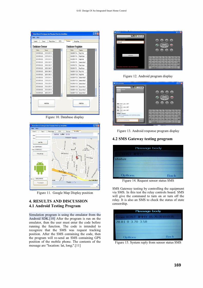
Figure 10. Database display
Figure 11. Google Map Display position
4. RESULTS AND DISCUSSION 4.1 Android Testing Program
Simulation program is using the emulator from the Android SDK.[10] After the program is run on the emulator, then the user must enter the code before running the function. The code is intended to recognize that the SMS was request tracking position. After the SMS containing the code, then the program will re-send an SMS containing GPS position of the mobile phone. The contents of the message are "location: lat, long;".[11]
Figure 12. Android program display
Figure 13. Android response program display
4.2 SMS Gateway testing program
Figure 14. Request sensor status SMS
SMS Gateway testing by controlling the equipment via SMS. In this test the relay controls board. SMS will give the command to turn on or turn off the relay. It is also an SMS to check the status of state censorship.
Figure 15. System reply from sensor status SMS
6-03 Design Of An Integrated Smart Home Control
169

At Figure 15, the image sensor system to send status data format "PIR LDR1 LDR2 Temp."Sample Image 4:17 "28.81 0 3.70 3:58",
meaning temperature Celsius 28.81, PIR = 0 (There is no movement), LDR1 = 3.70 (1-10 scale), LDR1 = 3:58 (1-10 scale). 4.3 Web ASP.Net
Figure 16. Web ASP . Net display
This ASP.Net web page will see the status of a state function of temperature sensors, PIR, and LDR2 LDR1. This user aims to facilitate users to access the system.[12] In this design still many shortcomings that must be repaired and updated. For the future, will be made some improvements such as:
1. Display programs are made more attractive, can be combined with the WPF technology. Net Framework.
2. Due to lack of time in this final, later in development there should be additional features in the database service.
3. Additional circuits for sensor signal isolation, so that the results obtained is stable.
4. Additional features on the web to be able to control the system.
5. CONCLUSION
The conclusion of this paper entitled “Design of
an Integrated Smart Home Control” is the combination of microcontroller technology, SMS Gateway, and the web has been successfully realized. The system has a temperature sensor, motion detector and light intensity. In its control, the system can control 8 relays and two stepper motors.
As a starter project, this is a first piece to develop better, complicated, and sophisticated smart home. Our trend today is green technology; it is a good challenge to develop a smart home with green technology.
REFERENCE [1] Heckman, David, A Small World: Smart
Houses and The Dream of The Perfect Day, Duke University Press, 2008.
[2] Smith, Ralph Lee, Smart House: The Coming Revolution in Housing, GP Pub., 1988.
[3] Trulove, James Grayson, The Smart House, Watson-Guptill, 2002.
[4] Briere, Danny, Pat Hurley, Smart Homes For
Dummies, 3rd
, Indianapolis, Wiley Publishing, Inc., 2007.
[5] Meyer, Gordon, Smart Home Hacks, O’Reilly Media, Inc. California, 2005.
[6] Wardhana, Lingga, Belajar Sendiri : Mikrokontroler AVR Seri ATMega8535 Simulasi, Hardware, dan Aplikasi, Andi Publisher, 2006.
[7] Darcey, Lauren, Shane Conder, Android: Wireless Application Development, Pearson Education, 2012.
[8] El-Rabbany, Ahmed, Introduction to GPS: The Global Positioning System, Artech House, Inc., 2002.
[9] Young, Michael, Google Maps Mashups with Google Mapplets, First Press, 2008.
[10] Meier, Rob, Professional Android Application Development, Wiley Publishing, 2009.
[11] Setiawan, Rachmad, Teknik Akuisisi Data, Graha Ilmu, Yogyakarta, 2008.
[12] Meng Lee, Wei, Practical, Net 2.0 Networking Projects, Apress, 2007.
The Proceedings of The 7th ICTS, Bali, May 15th-16th, 2013 (ISSN: 9772338185001)
170