design of an intelligent tool for the observation and
TRANSCRIPT

Titre:Title:
Design of an intelligent tool for the observation and follow-up of lockout procedures during maintenance activities on industrial machines
Auteurs:Authors: Damien Burlet-Vienney, Yuvin Chinniah et Ary Pizarro-Chong
Date: 2014Type: Article de revue / Journal article
Référence:Citation:
Burlet-Vienney, D., Chinniah, Y. & Pizarro-Chong, A. (2014). Design of an intelligent tool for the observation and follow-up of lockout procedures during maintenance activities on industrial machines. Open Journal of Safety Science and Technology,4(2), p. 106-118. doi:10.4236/ojsst.2014.42012
Document en libre accès dans PolyPublieOpen Access document in PolyPublie
URL de PolyPublie:PolyPublie URL:
https://publications.polymtl.ca/4812/
Version: Version officielle de l'éditeur / Published versionRévisé par les pairs / Refereed
Conditions d’utilisation:Terms of Use: CC BY
Document publié chez l’éditeur officielDocument issued by the official publisher
Titre de la revue:Journal Title:
Open Journal of Safety Science and Technology (vol. 4, no 2)
Maison d’édition:Publisher:
Scientific Research Publishing Inc.
URL officiel:Official URL:
https://doi.org/10.4236/ojsst.2014.42012
Mention légale:Legal notice:
Ce fichier a été téléchargé à partir de PolyPublie, le dépôt institutionnel de Polytechnique Montréal
This file has been downloaded from PolyPublie, theinstitutional repository of Polytechnique Montréal


Open Journal of Safety Science and Technology, 2014, 4, 106-118 Published Online June 2014 in SciRes. http://www.scirp.org/journal/ojssthttp://dx.doi.org/10.4236/ojsst.2014.42012
How to cite this paper: Burlet-Vienney, D., Chinniah, Y. and Pizarro-Chong, A. (2014) Design of an Intelligent Tool for the Observation and Follow-Up of Lockout Procedures during Maintenance Activities on Industrial Machines. Open Journal of Safety Science and Technology, 4, 106-118. http://dx.doi.org/10.4236/ojsst.2014.42012
Design of an Intelligent Tool for the Observation and Follow-Up of Lockout Procedures during Maintenance Activities on Industrial Machines Damien Burlet-Vienney1, Yuvin Chinniah2, Ary Pizarro-Chong2 1Mechanical and Physicalrisk Prevention Department, Institut de Recherche Robert-Sauvé en Santé et en Sécurité du Travail (IRSST), Montréal, Canada 2Department of Mathematics and Industrial Engineering, Polytechnique Montréal, Montréal, Canada Email: [email protected], [email protected] Received 20 April 2014; revised 20 May 2014; accepted 21 June 2014
Copyright © 2014 by authors and Scientific Research Publishing Inc. This work is licensed under the Creative Commons Attribution International License (CC BY). http://creativecommons.org/licenses/by/4.0/
Abstract Workers performing maintenance, repair and un-jamming operations on industrial machines and processes are required to follow lockout procedures in accordance with occupational health and safety regulations. However, industries seem to have difficulties in the appropriation and imple-mentation of lockout. Reports of severe accidents, often fatal, involving industrial machinery show the extent of the problem concerning the application of lockout procedures. In this context, an in-telligent tool incorporated at the design stage of a machine, which helps to apply and record lock-out procedures, could be useful. Thereby, the design of a laboratory prototype has been explored for a particular maintenance task on an automated plastic injection moulding machine. Its archi-tecture has been based on three electronic cards, sensors and wireless communications. Despite the limitations of the current version of the tool, the feasibility of designing an intelligent tool ca-pable of following and recording lockout procedures is demonstrated.
Keywords Machine, Lockout, Intelligent Tool, Audit, Injection Moulding
1. Introduction Maintenance activities occur regularly during the life of a machine and will occasionally require workers to en-

D. Burlet-Vienney et al.
107
ter a hazardous zone of the machine. Workers performing maintenance, repair and un-jamming operations on industrial machines and processes are required to follow lockout procedures in accordance with occupational health and safety regulations [1]-[4]. In essence, workers need to isolate and secure hazardous energies as well as to dissipate them before intervening on industrial equipment.
Recent publications show that the lack of lockout is an important factor in accidents involving machines dur-ing maintenance activities in the United States [5], Quebec (Canada) [6], France [7], and Great Britain [8]. A study has revealed that a proper application of OSHA 1910.417 in the US, during maintenance and repair opera-tions, could potentially avoid, each year, the death of 122 workers [9] [10].
Simply shutting off a machine, equipment or process may not completely control hazardous energies since re-sidual energy may still be present. Besides, even if the machine, equipment or process has been shut down and residual energy dissipated, an accident can still occur as a result of unexpected start-up due to human error or a malfunction in a control circuit [11]. Hence, the purpose of lockout is to protect personnel from injury from the inadvertent release of hazardous energy on machines, equipment and processes. Lockout is defined in the Ame- rican standard ANSI Z244.1 [12] as the “placement of a lock/tag on an energy isolating device in accordance with an established procedure, indicating that the energy isolating device shall not be operated until removal of the lock/tag in accordance with an established procedure”. Lockout is recognized in Canadian standard CSA Z460-13 as the primary method of hazardous energy control for tasks such as erecting, installing, constructing, repairing, adjusting, inspecting, un-jamming, setting-up, troubleshooting, testing, cleaning, dismantling, servic-ing and maintaining machines, equipment or processes [13]. However, the standard also mentions that if those tasks are integral to the production process or if traditional lockout prohibits completion of those tasks, other methods of risk reduction based on machine risk assessment can be used.
The main steps and the general sequence for a general lockout procedure are as follows: Preparation for shutdown; Machine, equipment or process shutdown (usually by turning off control elements); Machine, equipment, or process isolation (usually by turning off power elements); Application of lockout devices such as padlocks on power devices (e.g., circuit breakers, valves); Controlling stored energy (i.e., de-energization or dissipation of residual energies); and Verification of isolation by doing a startup test or by using measuring instruments.
A lockout procedure is supported by the lockout program which provides guidance to supervisors and workers on what is expected of them. The written program establishes the company’s general policies and procedures for implementing lockout as well as sets specific performance requirements for workers. It also provides the mecha- nism for regulatory compliance. Lockout programs include the following elements [12]-[15]: Identification of the hazardous energy covered by the program; Identification of the types of energy isolating devices; Identification of the types of de-energizing devices; Selection and procurement of protective materials and hardware; Assignment of duties and responsibilities; Determination of shutdown, de-energization, energization and start-up sequences; Written lockout procedures for machines, equipment and processes; Training of personnel; and Auditing of program elements.
Lockout is therefore an important mechanism to prevent accidents and injuries related to machinery. More-over, a new strategy to increase its implantation in industry appears to be necessary. Thus, a possible solution to 1) tackle the lack of implementation of lockout procedures in industry, 2) reduce the number of errors made by workers during lockout procedures, and 3) help in the review or audit process of lockout procedures and pro-grams is explored in this study.
2. Research Objectives The research objectives of the present study are: To evaluate the feasibility of developing an intelligent tool at the design stage of a machine for the observa-
tion and follow-up of lockout procedures in industry. To define the design parameters and technical specifications for such a tool in a laboratory setting by using
an industrial machine possessing numerous hazardous zones.

D. Burlet-Vienney et al.
108
It is expected that in a future research project, the tool will be put to the test in an industrial setting.
3. Method In order to achieve the research objectives, the method detailed below was followed:1) Literature review on the industrial audits of lockout procedures. This review confirmed that a tool for the
observation and follow-up of lockout procedures did not already exist.2) Familiarization with the functioning of an injection moulding machine located at the Quebec occupational
health and safety institute research (IRSST), especially by observing the machine while in operation and by performing functional tests in order to identify hazardous energies and danger zones for this machine.
3) Observation of the application of a lockout procedure on similar machines in industry to identify particulari-ties related to the application of lockout on this type of machine.
4) Drafting of lockout placards for the injection moulding machine.5) Research on sensors and on their proper installation on the injection moulding machine. The sensors are
needed to measure the change of state of the machine during the lockout procedure.6) Definition of the design requirements for the observation and follow-up tool. 7) Assembly of a preliminary prototype and integration on the injection moulding machine to verify the feasi-
bility of the approach.8) Tool performance tests to identify the limits of the tool in its current version.
4. Automated Injection Moulding Machine Based on machine risk assessment [4] [16], this section describes 1) the working principle of the injection moulding machine, 2) its hazardous zones, 3) its isolation devices, and 4) the lockout procedure on this machine.
4.1. Working Principle and Hazardous Zones The plastic injection moulding machine, shown in Figure 1, melts plastic granules contained in a hopper by carrying them to the heating barrel using a rotating screw. The molten plastic is subsequently injected under high pressure into the mould. The molten plastic inside the mould is then cooled down and the solidified plastic parts are ejected after the mould is opened. The automated cycle repeats itself. This machine was selected be-cause it presents a wide range of hazards (e.g., mechanical, thermal, chemical, hydraulic and electric). The haz-ardous zones were then identified in order to better determine the risks incurred by workers intervening on this type of machine. The hazardous zones found on the injection moulding machine are shown in Figure 2.
4.2. Hazardous Energies The implementation of a lockout procedure on a machine begins with the identification of all hazardous energy sources present in and around the machine. Thereby, the hazardous energies listed for the plastic injection moulding machine are:
Figure 1. Injection moulding machine in the laboratory at the IRSST.

D. Burlet-Vienney et al.
109
Figure 2. Hazardous zones of the injection moulding machine.
Electrical energy, namely three-phase low voltage (280 V) supply for the electric motor driving the hydraulic pump, and other components powered at very low voltage (24 V) as the control circuit, fans, etc. The risks to workers are electrification and electrocution.
Hydraulic energy, with some components such as pump, valves and cylinders which operate at maximum pressure of 260 bar (26 MPa). Possible injuries to the worker are contusions, fracture following the rupture of a hose, necrosis caused by small jets of high pressure oil, burns, irritations, etc.
Thermal energy including the plasticization cylinder which operates at a temperature of 380˚C to melt the plastic (Figure 3). Workers can get burnt by hot molten plastic or by the heating barrel.
Mechanical energy, with several moving parts such as the mould (clamping force of 350 kN), the screw, the mould closing mechanism (Figure 4), the injection unit and the ejectors. Injuries to workers range from sim-ple cuts, to serious crushing injuries and death.
4.3. Energy Isolating Devices During a lockout procedure, the hazardous energies must be controlled by energy-isolating devices which are mechanical elements which physically prevent both the transmission and the release of energy [17]. Nonetheless, the fact that energy can no longer be transmitted to the machine does not necessarily mean that the machine in question is at a safe energy level. The stored or potential energies will also have to be taken into account.The plastic injection moulding machine has two energy-isolating devices: The main circuit breaker which isolates the electrical energy supply to the machine. The water valve which isolates the water supply to the mould.
4.4. Lockout Procedures for Injection Moulding Machine The following section details the five main steps of the lockout procedure for the injection moulding machine: shutdown, isolation, application of lockout devices, dissipation and verification. Normal shutdown is carried out by pushing on the control knob (thus turning the electrical motor off) and by
setting to the “OFF” position the rotary switch in the machine’s local electrical panel. Isolation is the stage at which the worker puts the isolation devices in “OFF” position. Isolation is carried out
here by lowering the main circuit breaker lever and by closing the water valve. The application of lockout devices is the step during which the worker blocks or locks an energy isolating
device in order to prevent an inadvertent release of energy from the machine such as, for example, the acci-dental re-supply of electrical power. For the injection moulding machine, two locks with a multi-hasp each are enough for a worker. The first lock is intended for the lockup of the main circuit breaker. The second one locks up the water valve.
The dissipation of stored energies implies the elimination of all the potential and residual energies or the evacuation of hazardous substances. This step requires that the machine be taken to its lowest energy level. Measures must also be taken to prevent re-accumulation of these energies. The only hazardous energies stored by the injection moulding machine are the potential energy in the closing mechanism as well as the thermal energy. The absence of accumulators and capacitors that would store respectively hydraulic and

D. Burlet-Vienney et al.
110
Figure 3. Plasticization cylinder.
Figure 4. Mould closing mechanism with a hold and a sensor.
electrical energy simplifies this step. With regards to thermal energy, its dissipation happens naturally by convection. The potential mechanical energy in the closing mechanism, which exists because vertical actua-tors could move under their own weight, is controlled by means of a hold, shown in Figure 4.
The verification step consists of validating the effectiveness of the lockout by a restart test and/or by making measurements which confirm the absence of energy in the system. This verification ensures a redundancy for each step of the lockout and can, when this step is carried out correctly, protect the worker against errors made during the procedure. For the injection moulding machine, a restart test should be performed by fol-lowing the usual start-up procedure, i.e. by carrying out a reset and by pushing on the start button in the con-trol panel.
5. Design Requirements for an Electronic Tool for the Observation and Follow-Up of Lockout Procedures
5.1. Function Analysis A function analysis of the tool was carried out. In summary, the system will have to be equipped with intelli-
D. Burlet-Vienney et al.
111
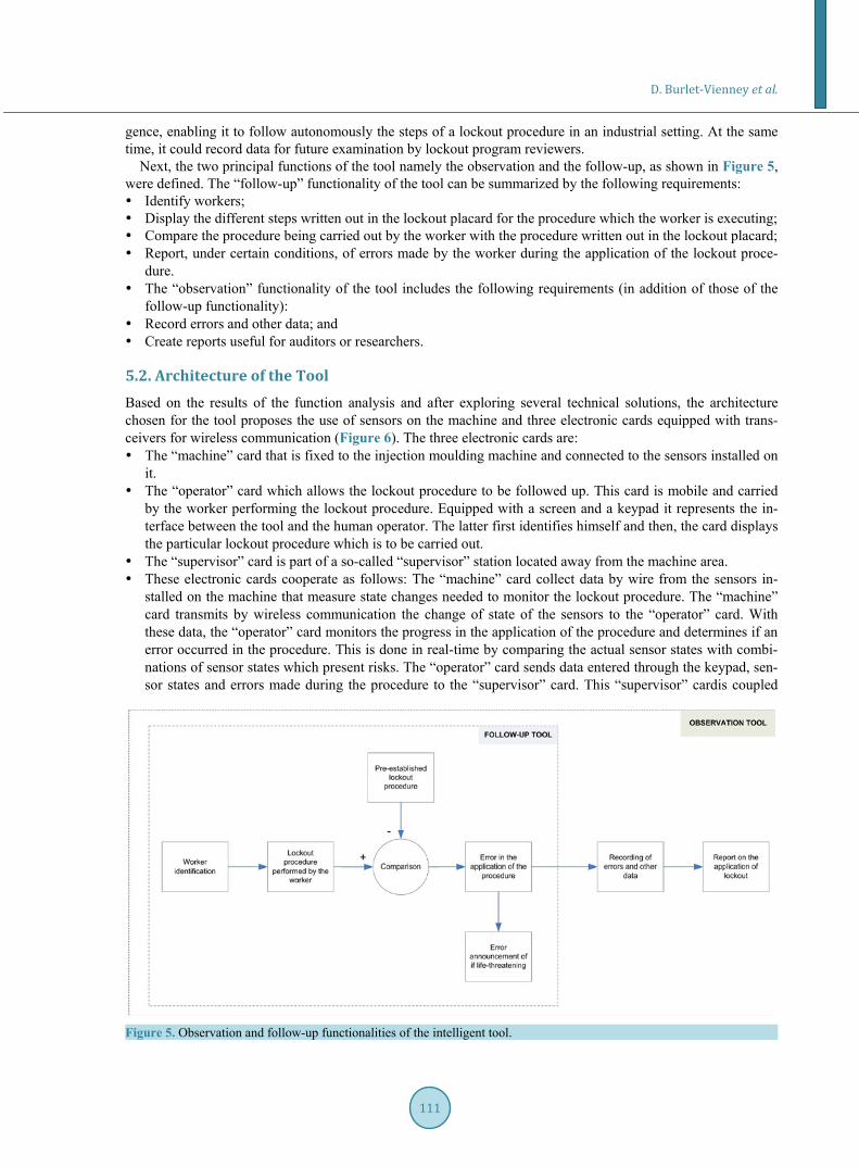
gence, enabling it to follow autonomously the steps of a lockout procedure in an industrial setting. At the same time, it could record data for future examination by lockout program reviewers.
Next, the two principal functions of the tool namely the observation and the follow-up, as shown in Figure 5, were defined. The “follow-up” functionality of the tool can be summarized by the following requirements: Identify workers; Display the different steps written out in the lockout placard for the procedure which the worker is executing; Compare the procedure being carried out by the worker with the procedure written out in the lockout placard; Report, under certain conditions, of errors made by the worker during the application of the lockout proce-
dure. The “observation” functionality of the tool includes the following requirements (in addition of those of the
follow-up functionality): Record errors and other data; and Create reports useful for auditors or researchers.
5.2. Architecture of the Tool Based on the results of the function analysis and after exploring several technical solutions, the architecture chosen for the tool proposes the use of sensors on the machine and three electronic cards equipped with trans-ceivers for wireless communication (Figure 6). The three electronic cards are: The “machine” card that is fixed to the injection moulding machine and connected to the sensors installed on
it. The “operator” card which allows the lockout procedure to be followed up. This card is mobile and carried
by the worker performing the lockout procedure. Equipped with a screen and a keypad it represents the in-terface between the tool and the human operator. The latter first identifies himself and then, the card displays the particular lockout procedure which is to be carried out.
The “supervisor” card is part of a so-called “supervisor” station located away from the machine area. These electronic cards cooperate as follows: The “machine” card collect data by wire from the sensors in-
stalled on the machine that measure state changes needed to monitor the lockout procedure. The “machine”card transmits by wireless communication the change of state of the sensors to the “operator” card. With these data, the “operator” card monitors the progress in the application of the procedure and determines if an error occurred in the procedure. This is done in real-time by comparing the actual sensor states with combi-nations of sensor states which present risks. The “operator” card sends data entered through the keypad, sen-sor states and errors made during the procedure to the “supervisor” card. This “supervisor” cardis coupled
Figure 5. Observation and follow-up functionalities of the intelligent tool.

D. Burlet-Vienney et al.
112
Figure 6. Overall picture of the chosen solution.
with a computer via a Universal Serial Bus (USB) connection. The computer is used as support for the re-cording of data sent by the “operator” card but also serves as a database for worker identification, passwords, various standard lockout procedures, and so on. Further explanations are given in the Section 5.3.
The solution, based on the three electronic cards, has the following advantages: The use of three cards, each responsible for one of the tool’s functions, offers more flexibility for software
development and for the choice of hardware, when compared to the use of a single, more complex card. In this solution, each card represents a separate module which can be developed independently.
The sensors will be connected to the “machine” card by wire. Compared to possible solutions having sensors with integrated wireless communication, the sensors will be of smaller size, will not disturb the normal func-tioning of the machine and will be less sensitive to interference.
The signal from the “machine” card and consequently the state of the machine’s energies will be accessible everywhere near the machine. Data recording and report generation can then be done away from the work area.
Free from measurement and management of data, the “operator” card is truly mobile and of suitable weight.
5.3. Prototype Development To validate the specification chosen, a prototype was developed in laboratory. The results below present the se-lected hardware and the development of functions “measure”, “follow” and “record”.
5.3.1. Selected Hardware Two types of micro-controllers were used: the PIC18F4550 and the dsPIC30F4011, both from Microchip. The PIC18F4550 micro-controller was selected for its capacity to communicate with a computer via USB and the dsPIC30F4011 micro-controller was selected for its speed of execution—up to 30 million instructions a sec-ond—and because it has the necessary number of ports to input and output signals (30 pins). The “machine” and “operator” cards use the dsPIC30F4011 micro-controller while the “supervisor” card, which is connected to the computer via USB, is fitted with the PIC18F4550.
5.3.2. Measuring States during Lockout Procedure Measuring the shutdown of the machine: While performing a lockout procedure, the worker first proceeds to
machine shutdown. In this study, the worker will use the main switch located on the machine’s electrical panel. A rotary potentiometer, shown in Figure 7, measures the position of the main switch. This solution

D. Burlet-Vienney et al.
113
was selected for this feasibility study because it was possible without any significant modifications to the machine hardware. In a normal shutdown procedure, the worker would stop the machine by first pushing on the control knob. Then, he would rotate the main machine switch.
Measuring the isolation of hazardous energies: Firstly, electrical energy isolation is confirmed by measuring the voltage downstream of the main circuit breaker. The sensor used is the voltage monitor PILZ PU3Z, shown in Figure 8, which continuously measures the voltage and sends a corresponding output signal. This device incorporates a high level of safety features. Secondly, for the isolation of the water circuit, an induc-tive proximity sensor, shown in Figure 9, was used. The sensor, model Turckuprox BI3U-M12-AP6X, de-tects the presence of the valve’s metallic lever when the latter is in the closed position. Note that this solution should be improved concerning the possibility of bypassing and issues with the reliability of information.
Measuring the application of lockout devices: Measuring the application of lockout devices consists of vali-dating the use of the locks on the energy-isolating devices. An electronic lock model 3510 from the RCI company, shown in Figure 10, was used to transmit this information. This lock has one part which is fixed and another which is attached to the main circuit breaker lever. When the latter is in the isolating position, the moving part of the lock fits into the fixed part and the lock is secured by the manual activation of a switch. The electronic lock is fed by a 24 V line, and therefore its output signal is 24 V when locked and 0V otherwise. This system is thus used to measure and validate the application of lockout devices on the main circuit breaker and on the water valve.
Measuring the dissipation of accumulated energies: As mentioned previously, residual energies are me-chanical and thermal in nature. At this stage, even if there is no hydraulic power accumulated in the injection moulding machine, the pressure in the hydraulic system will still be measured.
Figure 7. Rotary potentiometer installed on the electrical panel.
Figure 8. Inductive proximity sensor installed on the water circuit.

D. Burlet-Vienney et al.
114
Figure 9. Inductive proximity sensor installed on the wa-ter circuit.
Figure 10. Electronic lock installed on the main circuit breaker lever.
- Thermal energy: The sensor used to measure if the thermal energy was dissipated was installed in the vicin-ity of the plasticization cylinders. The constraints on the choice of the sensor were an environment whose temperature went up to 350˚C and its dimensions, which needed to be small. The sensor selected is a tem-perature switch by Stancor. Its change of state and resistance was regulated and tested for 43˚C, a tempera-ture value that is considered safe.
- Mechanical energy: When the movement of the mould is stopped, the hydraulic cylinders of the closing mechanism store potential energy. It is thus important to mechanically block the cylinder before performing

D. Burlet-Vienney et al.
115
an intervention on the machine. A proximity inductive sensor, identical to that used for the water valve, de-tects the presence of a hold installed in the machine’s closing mechanism. To ensure that the hold remains installed, the state of the proximity sensor must be read periodically. It’s important that the hold be installed last, after the verification step, for safety reasons.
- Hydraulic energy: To detect oil pressure, a pressure sensor was installed in one of the available entries of the hydraulic system. The selected pressure sensor is Endress Hauser Ceraphant PTP31. This sensor shows on a screen the numerical value of the pressure in the machine’s hydraulic system. It sends a corresponding 24V signal to confirm the absence of hydraulic pressure.
Measuring the verification step during the lockout procedure: This stage is often comprised of a restart test. The principle by which this step is measured is the same as that used for machine shutdown: the position of the rotary switch is measured. More precisely, one will have 1) to detect the moving of the switch from the OFF to the ON position, 2) to check, respectively, by using the voltage monitor and the pressure sensor, the absence of voltage in the electrical circuit and the absence of pressure in the hydraulic system, and 3) to de-tect the moving of the switch from the ON to the OFF position. If the “machine” card collects the data in that order, the verification step is considered to have been successfully accomplished.
5.3.3. Follow-Up Functionality This objective can be subdivided in three functions: 1) identifying the worker, 2) displaying the lockout proce-dure and 3) alerting the worker when he makes a life-threatening mistake. Identifying the worker. Before beginning the lockout procedure, the worker will have to identify himself by
entering his username and password using the keypad located on the “operator” card. The information is then validated through the “supervisor” card. Other information such as “work yet to be performed” could be added in the future by repeating the same procedure used to obtain the worker’s name and password. With this information in hand, it will be possible to analyze with greater certainty the conditions under which the lockout procedure took place.
Displaying the lockout procedure. The “operator” card shows the steps of the lockout procedure with an LCD screen. These data are from the database associated with the “supervisor” card.
Managing the interruptions. All errors in the lockout procedure (e.g., wrong sequence, omission of a step) will be recorded by the “supervisor” card. However, a decision was made to warn the worker only if a mis-take he made had ill-consequences for his health and safety. This decision aims to make the observation of the lockout procedure as intervention-free as possible. However, a feedback with the employee for all errors made during the application of the procedures will be done later. Thus, the supervisor may use the error re-porting during a periodic update or an audit.
To program the software alerts, every step of the lockout procedure was represented by a letter, then logical sequences have been defined to ensure a safe lockout procedure for the worker. To better understand this logic, consider the installation of the electronic lock on the main circuit breaker. The installation of the electronic lock on the main circuit breaker must occur after the machine is stopped and the main circuit breaker is off. The re-start test and the installation of the hold must necessarily happen after this step. If one of these conditions is not satisfied and the worker installs the lock, an audio-visual alarm will notify him of his mistake. Continuing this example, if the worker checks the water pressure or the temperature before installing the electronic lock on the main circuit breaker, he performs the wrong sequence. Nonetheless, he does not make an error which has imme-diate ill-consequences to his health or his safety.
5.3.4. Recording and Evaluation The recording functionality is performed by the “supervisor” card in conjunction with the computer. Together they: 1) record and validate worker identification via the “operator” card, 2) record each action executed by the worker using data sent by the “machine” card, and 3) record all errors made during the lockout procedure. The end result of these recordings is the generation of reports which can be useful for auditors. Thus, to match all the information and obtain a useful report, programming work and creation of graphical interfaces has been done using an object-oriented programming software developed under the Java Enterprise Edition platform.
6. Discussion In this section, the results of experimental studies on the prototype are presented and the main limitations of the

D. Burlet-Vienney et al.
116
tool are identified.
6.1. Experimental Studies A working prototype of the tool was then assembled (Figure 11). Several series of tests were performed to en-sure that the tool in its current architecture is viable, but also for issues related to its development. The tests re-corded focused on 1) the startup and the overall functioning of the three electronic cards, 2) the wireless com-munications, 3) the authentication module, 4) the processing of information collected by sensors, and 5) the triggering of the alarm in case of dangerous error for the worker. Test results showed that the tool was function-ing as expected but had some reliability issues. Also, it is necessary to improve the reliability of the tool accord-ing to the principles outlined in the following paragraph.
6.2. Reliability of the Prototype The reliability of the electronic tool and its peripherals remains problematic. A defect or an accumulation of de-fects could potentially lead to a loss of one or several tool functionalities. Possible degradations include: mal-functioning sensors, disconnected cables in the machine’s junction box, malfunctions of any micro-controller port and defects in the micro-controller’s internal architecture or code.
Appropriate solutions could involve making use of accepted principles of redundancy and monitoring perti-nent to control systems for safety applications. Standards such as IEC 61508-2 [18], IEC 62061 [19] and ISO 13849-1:2006 [20] could be consulted to improve reliability when designing and developing the electronic tool. There could for example be, in the same card, two micro-controllers having the same responsibilities. The in-formation received by each micro-controller would be compared and, if identical, would be displayed on the screen or otherwise sent to another card. The safety of the software will have to be reconsidered on the basis of the principles of safe programming stated in standards such as IEC 61508-2 (2010) and IEC 62061 (2005). The relevance of certified safety components such as safety programmable logic controllers (safety PLC) built for safety, controllers of discrepancy, and safety position switches with positively driven contacts will have to be explored.
Moreover, the tool will have to be robust with regards to electromagnetic interferences emitted by neighbour-ing machines. It will also have to be resistant to harsh environments containing, for example, large amounts of moisture or dust.
6.3. Improvement to Be Made Several hardware solutions should be reconsidered since some of them were chosen temporarily. These are: Replace the switch of the electronic lock by a key switch to control the removal of the padlock. Install an electronic lock on the water valve, or replace it with a lockable electronic valve.
Figure 11. Integration of the three electronic cards onto the injection moulding machine.

D. Burlet-Vienney et al.
117
Replace the proximity sensors by devices more reliable and difficult to bypass (e.g., safety electro-mechani- cal switch).
Change the hold to the mould closing mechanism to make it accommodate a padlock.
6.4. Flexibility and Industrial Trial The tool will have to demonstrate a certain degree of flexibility before its trial in industry. In a factory, each maintenance, repair or un-jamming task can require its own procedure. However, the current version of the tool can be used for only one particular lockout procedure. Another aspect related to flexibility is the tool’s ability to observe and follow-up the application of lockout procedures spread out over several work shifts. Moreover, it would be necessary to consider repair or maintenance operations involving the simultaneous presence of several workers, for example, during complex lockout procedures. Lastly, to make the tool less cumbersome and less prone to wiring problems, the use of wireless sensors will have to be explored. This approach would make the tool more versatile and would solve the problem of distance between 1) the machine and the energy-isolating devices and 2) sensor locations (danger zones) and the “machine” card. The problem of distance is bound to emerge in a factory setting, especially with large machines or industrial processes.
7. Conclusions In this paper, an intelligent tool was developed to observe and follow lockout procedures on an injection mould-ing machine in a laboratory setup. The tool consisted of three wireless communication electronic cards: The “machine” card installed on the injection moulding machine which measures state changes of energies,
isolating devices, and lockout devices during the application of the lockout procedure. The “operator” card which allows workers to identify themselves at the beginning of the procedure, which
displays the steps of the lockout procedure written for the injection moulding machine and warns if an error that can lead to a dangerous situation occurs.
The “supervisor” card that authenticates workers, records the data collected during the lockout procedure, and generates a report for each lockout procedure applied.
The prototype developed and the tests carried out showed the feasibility of such a tool. Also, this type of equipment could certainly be incorporated into the design of some machines to facilitate the application of lockout procedures by workers, support the audit and be used as an educational tool for training purposes. This study is in line with the principle of risk reduction through design, which is the most effective method to reduce risks [21] [22].
References [1] Occupational Health and Safety Administration (1989) OSHA 1910.147—Regulations Standards—29 CFR, The Con-
trol of Hazardous Energy (Lockout/Tagout). https://www.osha.gov/pls/oshaweb/owadisp.show_document?p_id=9804&p_table=STANDARDS
[2] Quebec Government (2014) Regulation Respecting Occupational Health and Safety (c. S-2.1, s.223). http://www2.publicationsduquebec.gouv.qc.ca/dynamicSearch/telecharge.php?type=3&file=/S_2_1/S2_1R13_A.HTM
[3] The European Parliament and of the Council (2006) Directive 2006/42/CE on Machinery. http://eur-lex.europa.eu/LexUriServ/LexUriServ.do?uri=OJ:L:2006:157:0024:0086:EN:PDF
[4] International Standard Organization (2010) Safety of Machinery—General Principles for Design—Risk Assessment and Risk Reduction (ISO 12100:2010). The Organization, Geneva.
[5] Bulzachelli, M.T., Vernick, J.S., Sorock, G.S., Webster, D.W. and Lees, P.S.J. (2008) Circumstances of Fatal Lock-out/Tagout Related Injuries in Manufacturing. American Journal of Industrial Medicine, 51, 728-734. http://dx.doi.org/10.1002/ajim.20630
[6] Chinniah, Y. and Burlet-Vienney, D. (2013) Study on Lockout Procedures for the Safety of Workers Intervening on Equipment in the Municipal Sector in Québec. International Journal of Occupational Safety and Ergonomics, 19, 495-411.
[7] Blaise, J.-C. and Welitz, G. (2010) Operating on Machinery out of Production Modes: Principles and Accidentology. Proceedings of the 6th International Conference Safety of Industrial Automated Systems—SIAS 2010, Tampere, 14-15 June 2010.
[8] Shaw, S. (2010) Machinery Accidents—Contributory Factors. Proceedings of the 6th International Conference Safety

D. Burlet-Vienney et al.
118
of Industrial Automated Systems—SIAS 2010, Tampere, 14-15 June 2010. [9] US Department of Labor Statistics (2007) Census of Fatal Occupational Injuries. Archived Data—Fatality Rates (Em-
ployment-Based) 1992-2007. http://www.bls.gov/iif/oshcfoiarchive.htm#rates [10] Bulzachelli, M.T., Vernick, J.S., Webster, W. and Lees P.S.J. (2007) Effects of the Occupational Safety and Health
Administration’s Control of Hazardous Energy (Lockout/Tagout) Standard on Rates of Machinery-Related Fatal Oc-cupational Injury. Injury prevention, 13, 334-338. http://dx.doi.org/10.1136/ip.2007.015677
[11] Kelley, S. (2001) LockOutTagOut: A Practical Approach. The American Society of Safety Engineers, Des Plaines. [12] American National Standard Institute/American Society of Safety Engineers (2003) Control of Hazardous Energy,
Lockout/Tagout and Alternative Methods (ANSI/ASSE Z244). The American Society of Safety Engineers, Des Plaines.
[13] Canadian Standards Association (2013) Control of Hazardous Energy: Lockout and Other Methods (CSA Z460-13). The Association, Mississauga.
[14] Chinniah, Y. (2010) Equipment Lockout—A Review of Written Lockout Programs in Quebec. Professional Safety, 55, 38-43.
[15] Burlet-Vienney, D., Jocelyn, S., Chinniah, Y., Daigle, R. and Massé, S. (2009) Verifying the Content of Lockout Pro-grams. http://www.irsst.qc.ca/media/documents/PubIRSST/RF-635.pdf
[16] Chinniah, Y., Paques, J.-J. and Champoux, M. (2007) Risk Assessment and Risk Reduction: A Machine Safety Case Study from Quebec. Professional Safety, 52, 49-56.
[17] Canadian Standards Association (2004) Safeguarding of Machinery (CSA Z432-04). The Association, Mississauga. [18] International Electrotechnical Commission (2010) Functional Safety of Electrical/Electronic/Programmable Electronic
Safety-Related Systems—Part 2: Requirements for Electrical/Electronic/Programmable Electronic Safety-Related Sys-tems (IEC 61508-2). The Commission, Geneva.
[19] International Electrotechnical Commission (2005) Safety of Machinery—Functional Safety of Safety-Related Electri-cal, Electronic and Programmable Electronic Control Systems (IEC 62061). The Commission, Geneva.
[20] International Standard Organization (2006) Safety of Machinery—Safety-Related Parts of Control Systems—Part 1: General Principles for Design (ISO 13849-1:2006). The Commission, Geneva.
[21] American National Standard Institute/ American Society of Safety Engineers (2011) Prevention through Design: Guidelines for Addressing Occupational Hazards and Risks in Design and Redesign Processes (ANSI/ASSE Z590.3). The American Society of Safety Engineers, Des Plaines.
[22] Manuele, F.A. (2008) Prevention through Design. Professional Safety, 53, 28-40.