design of an ultrasonic motor with multi-vibrators · design of an ultrasonic motor with...
TRANSCRIPT
Li et al. / J Zhejiang Univ-Sci A (Appl Phys & Eng) 2016 17(9):724-732
724
Design of an ultrasonic motor with multi-vibrators*
Chong LI1, Cun-yue LU†‡1, Yi-xin MA1, Shi-yang LI1, Wei-qing HUANG2 (1Department of Instrument Science and Engineering, Shanghai Jiao Tong University, Shanghai 200240, China)
(2Precision Driving Lab, Nanjing University of Aeronautics and Astronautics, Nanjing 210016, China) †E-mail: [email protected]
Received Nov. 25, 2015; Revision accepted May 27, 2016; Crosschecked Aug. 23, 2016
Abstract: This paper presents and verifies a new idea for constructing an ultrasonic motor (USM). The stator contains several vibrators fabricated by bonding piezoelectric ceramics (PZTs) to a metal base. When two alternating current (AC) voltages with a 90° phase difference are applied to the PZTs, longitudinal and bending modes are excited in the vibrator. The bending vibrations of the vibrators are stacked to form the torsional vibration of the stator, ultimately generating longitudinal-torsional composite vi-bration. Both vibrators and the stator are excited to the resonance state. A standing wave is formed by superposition of longitudinal and torsional modes. The proposed motor is an in-plane vibration motor because the vibrations of the stator are in the circum-ferential plane. The finite element method (FEM) is used to validate the feasibility of the proposed motor. The fabricated stator contains five vibrators. The tested resonance frequencies of longitudinal and torsional modes are 44.42 kHz and 43.83 kHz, re-spectively. The stall torque is 0.3 N·m and no-load speed is 45 r/min. The highest efficiency is 30%. The applied driving voltage is 100 Vo-p (peak voltage) at 43.9 kHz. The designed motor is a parallel-actuated integral motor. It allows the vibrators to operate synchronously, and overcomes asynchronous issues that occur in traditional multi-vibrator motors.
Key words: Ultrasonic motor (USM), Standing wave, In-plane vibration, Multi-vibrator http://dx.doi.org/10.1631/jzus.A1500316 CLC number: TM356
1 Introduction Ultrasonic motors (USMs) use the inverse
piezoelectric effect of piezoelectric elements to excite micro-vibrations of the stator. The key advantages of USMs over conventional electromagnetic motors are compactness, quick response, and no electromagnetic interference (Yang et al., 2009; He et al., 2011; Al-Budairi et al., 2013). Therefore, USMs are widely used in robotics, precision instruments, and aerospace engineering.
To generate the required output displacement, the frequency of the applied electric field should ap-
proach the resonance frequency of the USM. The effective bandwidth of USMs is only several Hertz, which greatly limits their applications. Previous studies have noted a specific increase in the band-width of multi-vibrator motors when these vibrators work synchronously (Jin et al., 2011; Park and He, 2012; Hou et al., 2013). Other studies have reported the superimposition of output torque by concurrently using multiple piezoelectric vibrators (Zhao, 2010; Zhu et al., 2010; Oh et al., 2012). Therefore, multi-vibrator motors have become a popular re-search topic.
Motors with multi-vibrators are mainly classi-fied into two types: those with independent multi- vibrators and those with integrated multi-vibrators (Petit and Gonnard, 2009; Liu et al., 2012a; 2012b; 2013; Lu et al., 2013). Liu et al. (2013) developed a USM with four independent vibrators, achieving an efficiency of 22%. The vibrators may display varying characteristics because of machining and rigging
Journal of Zhejiang University-SCIENCE A (Applied Physics & Engineering)
ISSN 1673-565X (Print); ISSN 1862-1775 (Online)
www.zju.edu.cn/jzus; www.springerlink.com
E-mail: [email protected]
‡ Corresponding author
* Project supported by the National Natural Science Foundation of China (No. 11174206), the Open Fund of State Key Laboratory of Ocean Engineering (No. 0507), and the Shanghai Aerospace Science and Technology Innovation Fund (No. 201347), China
ORCID: Chong LI, http://orcid.org/0000-0002-7485-7248 © Zhejiang University and Springer-Verlag Berlin Heidelberg 2016
Li et al. / J Zhejiang Univ-Sci A (Appl Phys & Eng) 2016 17(9):724-732
725
errors, which decrease the stability and efficiency of the motor when the vibrators are excited at the same frequency (Zhao, 2010). Therefore, the main chal-lenge for independent multi-vibrator motors is how to achieve the collaboration of all vibrators. Integrated multi-vibrator motors refer to motors whose vibrators are interlinked to form an integrated structure (Guo et al., 2003; Liu et al., 2012b; Cheon et al., 2015; Yang et al., 2015). Petit and Gonnard (2009) developed an integrated stator. In the design, vibrators were uni-formly distributed along the circumference of two rings. This approach enabled the vibrators to coher-ently actuate the rotor. However, the vibrators are in the non-resonant state, resulting in reduced motor efficiency (approximately 20%). The multi-vibrator motors generally employ Langevin-type vibrators which are large and structurally sophisticated. Thus, such motors are difficult to miniaturize.
To enhance the efficiency of integrated multi- vibrator motors while miniaturizing the motor size, a novel method for constructing a motor with multi- vibrators is proposed. The motor adopts patch-type vibrators. The vibrator is constructed by bonding piezoelectric ceramics (PZTs) to a metal base. Com-pared with Langevin vibrators, the proposed vibrator is more suitable for miniaturization. The vibrators are connected to form the stator which is used to con-struct linear motors or rotary motors. The vibrators and the stator are driven at the resonance state, which is beneficial for improving motor efficiency. The PZTs are used to excite the longitudinal and torsional modes of the cylindrical stator. The finite element method (FEM) is adopted to compare the perfor-mances of stators with varying numbers of vibrators and analyze the driving principle of the designed motor. Finally, a prototype motor with five vibrators is fabricated, and its vibration and mechanical output characteristics are measured.
2 Construction methods Linear motors using in-plane longitudinal and
bending modes have been mass-produced and widely used, because they are simple in structure and have advantages of increased performance and compact-ness (Zhao, 2010). Based on the design principle of in-plane vibration motors, an improved vibrator is
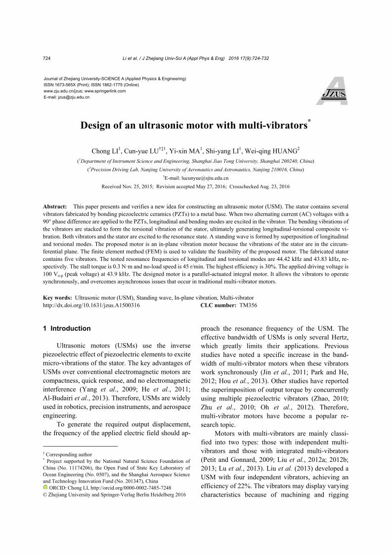
developed. Fig. 1 shows the vibrator, constructed by bonding two PZTs (I and II) to the metal base. PZTs are polarized along the thickness direction.
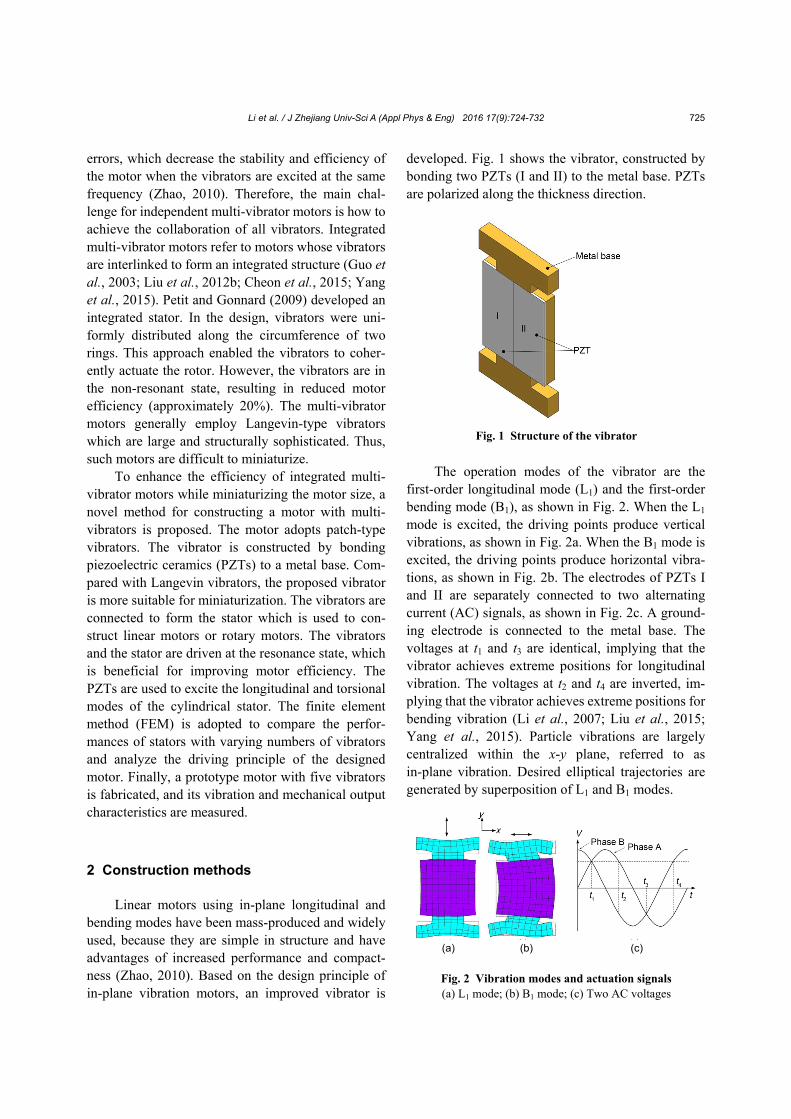
The operation modes of the vibrator are the first-order longitudinal mode (L1) and the first-order bending mode (B1), as shown in Fig. 2. When the L1 mode is excited, the driving points produce vertical vibrations, as shown in Fig. 2a. When the B1 mode is excited, the driving points produce horizontal vibra-tions, as shown in Fig. 2b. The electrodes of PZTs I and II are separately connected to two alternating current (AC) signals, as shown in Fig. 2c. A ground-ing electrode is connected to the metal base. The voltages at t1 and t3 are identical, implying that the vibrator achieves extreme positions for longitudinal vibration. The voltages at t2 and t4 are inverted, im-plying that the vibrator achieves extreme positions for bending vibration (Li et al., 2007; Liu et al., 2015; Yang et al., 2015). Particle vibrations are largely centralized within the x-y plane, referred to as in-plane vibration. Desired elliptical trajectories are generated by superposition of L1 and B1 modes.
Fig. 2 Vibration modes and actuation signals (a) L1 mode; (b) B1 mode; (c) Two AC voltages
(a) (b) (c)
Fig. 1 Structure of the vibrator

Li et al. / J Zhejiang Univ-Sci A (Appl Phys & Eng) 2016 17(9):724-732
726
Several vibrators are connected to form a struc-ture, as shown in Fig. 3. The vibrator is indicated by dotted lines. The L1 and B1 modes of each vibrator are simultaneously excited by applying two AC voltages with a 90° phase difference, and then the corre-sponding L1 and B1 modes of the flat multi- vibrator structure are formed. The structure is suitable for constructing linear motors.
A cylindrical multi-vibrator structure is formed
by folding multiple flat vibrators along the x direc-tion. The folded structure, as shown in Fig. 4, is used as the stator of the proposed motor. Fig. 4 indicates that the diameter of the stator is proportional to the number of vibrators. The vertical vibrations of the flat vibrators are converted into axial vibrations of the cylindrical stator. The horizontal vibrations of the flat vibrators are converted into circumferential vibrations of the cylindrical stator. Therefore, the bending mode of the flat multi-vibrator structure is converted into the torsional mode of the cylindrical multi-vibrator structure.
The first-order longitudinal mode (L1) and the second-order torsional mode (T2) of the stator are indicated in Fig. 5. The stator consists of five vibra-
tors. When the two modes are excited simultaneously, an elliptical motion is generated at the driving tip of the stator. This structure can be used to construct rotary motors. Fig. 5b illustrates the conversion from the B1 mode of a single vibrator to the T2 mode of the cylindrical stator. Under the effect of two AC volt-ages with a phase difference of 90°, all the vibrators produce bending vibrations. However, the bending vibrations of the vibrators are restricted by each other because all the vibrators are part of the cylindrical stator. The angle between the bending vibration di-rections of two adjacent vibrators is 72° (2π/5). This paper uses the differences in the bending vibration directions of the vibrators to form the torsional vi-bration of the stator. That is, the torsional vibration of the cylindrical stator is formed by the superimposition of the bending vibrations of multiple vibrators.
3 Simulation analysis
The dimensions of the ring vibrator can be de-
rived using the dimensions of the flat vibrator. The parameters of the two structures are shown in Fig. 6. The length, width, and thickness of the flat vibrator are L, H, and T, respectively. h1 represents the height of the driving terminals, h2 represents the symmet-rical groove depths, and d1 and d2 both represent the symmetrical groove widths. Among these parame-ters, H and T are directly converted to the height and thickness of the ring vibrator. L is converted to the arc length of the ring vibrator. The radius parameter R corresponding to the midline of the ring vibrator can be deduced from the parameter L. The relation-ship between the two parameters is
,R L (1)
Fig. 3 Flat multi-vibrator structure
Fig. 5 Vibration modes of the stator (a) L1 mode; (b) T2 mode
(a) (b)
Fig. 4 Stators with varying numbers of ring vibrators(a) Three vibrators; (b) Four vibrators; (c) Five vibrators
(a) (b) (c)

Li et al. / J Zhejiang Univ-Sci A (Appl Phys & Eng) 2016 17(9):724-732
727
where φ is the central angle of the ring vibrator de-termined by 2/n (n represents the number of vibra-tors). The groove radians (φ1 and φ2) on two ends of the ring vibrator are deduced from the groove widths (d1 and d2) of the flat vibrator, which can be ex-pressed as follows:
1 12 ( 2 ),L d R (2)
2 22 ( 2 ),L d R (3)
where L−2d1 represents the arc length of the ring vi-brator adhering to the PZTs; L−2d2 represents the arc length of the ring vibrator at the thin diameter; φ−2φ1 and φ−2φ2 represent the corresponding central angles.
FEM analysis was carried out to validate the proposed stator. The FEM software, ANSYS, was employed to separately analyze the vibration modes of the flat multi-vibrator structure and the cylindrical multi-vibrator structure.
The dimensions of the ring vibrator were cal-culated from the parameter values listed in Table 1. The thickness of the PZTs, the thickness of the metal base to which the PZTs were adhered, and the thickness of the other metal base were set at 0.5 mm, 2.5 mm, and 3 mm, respectively. To build the FEM model, the stator is meshed using 3D coupled-field solid elements SOLID5. The element has eight nodes with up to six degrees of freedom at each node. The finite element model of the stator consists of 2820 elements and 4560 nodes, as shown in Fig. 5. Prop-erties of the materials used for the simulation model are listed in Table 2. Phosphor bronze was used for the metal body. PZT–8 was employed in piezoelec-tric elements. Resonance frequencies of the L1 mode (fL) and the B1 mode (fB) of the flat structures with five and ten vibrators were calculated. The frequency difference of the two modes (Δf) was also obtained. The results are listed in Table 3.
Table 1 Size of the flat vibrator
Parameter Value (mm) Parameter Value (mm)
L 20 d2 5
H 30 h1 4
h 17.8 h2 2.1
d1 1.1 T 3
Table 2 Material constants
Material Density (kg/m3) Poisson’s ratio Elastic modulus (×1010 N/m2) Piezoelectric constant (C/m2)
PZT 7500 0.31
13.9 7.78 7.43 0 0 0
13.9 7.43 0 0 0
11.5 0 0 0
2.56 0 0
3.06 0
2.56
0 0 1.23
0 0 1.23
0 0 2.89
0 4.96 0
4.96 0 0
0 0 0
Cu 8900 0.30 11.7
Material Mechanical qual-
ity factor, Qm Relative dielectric
constant, ε1/ε0 Relative dielectric constant,
ε3/ε0
PZT 800 370 635
Cu
Table 3 Resonance frequencies of the flat multi-vibrator structures
n fL (kHz) fB (kHz) Δf (kHz)
5 45.826 48.534 2.708
10 46.452 47.386 0.934 Fig. 6 Parameters of the flat and ring vibrators

Li et al. / J Zhejiang Univ-Sci A (Appl Phys & Eng) 2016 17(9):724-732
728
For stators with three and four vibrators, the arc lengths of the PZTs are relatively large and the re-quired PZTs are difficult to process. Therefore, this paper analyzed the performances of stators with five to seven vibrators. The peak value of the excitation voltages was set at 100 V. Results are listed in Table 4. UR, Uθ, and Uz respectively represent the radial, tangential, and axial displacements of point a (Fig. 4). Table 4 indicates that the resonance fre-quencies of the L1 mode (fL1) and T2 mode (fT2) of the stators are all close, despite the differences in the number of vibrators. The radial displacement is rel-atively small, which is consistent with the design of the circumferential in-plane vibration. Tables 3 and 4 show that an increase in the number of vibrators causes the resonance frequencies of the flat multi- vibrator structure to approach those of the cylindrical stator. The reason is that a structure with a fixed number of flat vibrators constitutes a finite surface, while a cylindrical multi-vibrator structure contain-ing the corresponding number of vibrators constitutes an infinite surface. If fL is close to fB of a structure with an infinite number of flat vibrators, then fL1 is also close to fT2 of the cylindrical stator with corre-sponding dimensions.
To analyze the driving characteristics of the motor, transient analysis was performed under a free edge boundary condition. Table 4 shows that the output displacement was the highest when the stator contained five vibrators. Thus, the number of vibra-tors for the transient analysis was set at five. Two AC voltages with a frequency of 46.8 kHz, a peak value of 100 V, and a phase difference of 90° were applied to the PZTs. Forty sample points were selected in each excitation cycle. The FEM model of the ring vibrator is illustrated in Fig. 7. Because all vibrators operated synchronously, the vibration characteristics of the stator were determined by one vibrator. Along the direction indicated in Fig. 7, 15 nodes on the
outer edge of the ring vibrator were successively selected and coded in ascending order. The dis-placement curves of the selected nodes are shown in Fig. 8. The displacement curves of nodes 1 and 15 coincide completely.
Fig. 8a shows that the longitudinal displace-
ments vary according to a sine law. Differences in the amplitudes are relatively large, and the amplitudes of the nodes at the two ends of the arrow are greater than those of the nodes at the center. In addition, the lon-gitudinal displacements of nodes 2 and 4 are differ-ent, indicating deviations in the amplitude of the nodes corresponding to two sides of the vibrator. This is due to the local deformations at the driving terminals when the B1 mode of the vibrator is con-verted into the T2 mode of the stator. The defor-mation causes longitudinal vibrations of the selected nodes to vary. Moreover, the groove changes the stiffness of the stator, which also causes deviations in the longitudinal displacements. These factors create a specific amount of phase difference in the longitu-dinal displacements of the nodes. In other words, the longitudinal displacements of the nodes are asynchronous.
Fig. 8b shows that the tangential displacements also vary according to a sine law. The tangential displacements are synchronous. Differences in the amplitudes are relatively small, and the amplitudes of the nodes at the center of the arrow are greater than those of the nodes at the two ends. Figs. 8a and 8b indicate that the longitudinal and torsional dis-placements of nodes 2 and 3 are approximate. It is beneficial to the stable operation of the motor when these nodes are selected as the driving points.
Table 4 Performances of the stators with varying num-bers of vibrators
n fL1
(kHz) fT2
(kHz) UR
(μm) Uθ
(μm) Uz
(μm)
5 46.852 46.818 0.22 1.78 1.65
6 46.568 46.751 0.17 1.28 1.59
7 46.862 46.570 0.13 1.08 1.29
Fig. 7 FEM model of the ring vibrator

Li et al. / J Zhejiang Univ-Sci A (Appl Phys & Eng) 2016 17(9):724-732
729
4 Experiments
A prototype motor was fabricated, as shown in Fig. 9. The motor consists of a stator, two rotors, and the preloading mechanism. The stator contains five vibrators. The rotors are pressed to each end of the stator by coiled springs. In order to produce perfect bonding between the PZT plate and the metal base, we first fabricated the PZT plate, and then slightly adjusted the dimensions of the metal base according to the fabricated PZT plate. The inner diameter, outer diameter, and height of the fabricated stator are 28 mm, 35 mm, and 30 mm, respectively.
A scanning laser Doppler vibrometer (LDVS) was used to measure the vibration characteristics of the fabricated stator, as shown in Fig. 10. The L1 and T2 modes of the stator are simultaneously excited when the metal base is grounded, the upper surface electrode of PZT I in each vibrator is connected to an excitation signal, and the electrode of PZT II is left
floating. The test method is shown in Fig. 11. The stator is placed horizontally. A reflective tape is ad-hered along the length direction of the stator, as shown in zone A of Fig. 11. The reflective tape uni-directionally returns the vertical incident laser along the original path. The angle between line OP and x axis is θ. When the direction of the incident laser is shown in Fig. 11, the tangential vibration of the point P (i.e., v) has a vibration component in the vertical direction (the direction of the incident laser). Under the influences of Poisson’s ratio and the grooves, the axial vibration of point P also produces a vibration component in the vertical direction. It is the physical basis for using an LDVS to simultaneously test the resonance frequencies of the L1 and T2 modes. The frequency response curve is illustrated in Fig. 12.
Fig. 8 Longitudinal displacement (a) and torsional dis-placement (b) curves of the nodes Note: for interpretation of the references to color in this figurelegend, the reader is referred to the web version of this article
8.504 8.512 8.520 8.528 8.536 8.544 8.552-3
-2
-1
0
1
2
3
Tor
sion
al d
ispl
ace
men
t (μ
m)
Time (ms)
1 2 3 4 5 6 7 8 9 10 11 12 13 14 15
(b)
(a)
8.504 8.512 8.520 8.528 8.536 8.544 8.552-2.1
-1.4
-0.7
0.0
0.7
1.4
2.1 1 2 3 4 5 6 7 8 9 10 11 12 13 14 15
Long
itud
inal
dis
pla
cem
ent
(m
)
Time (ms)
Fig. 10 Stator vibration test system
Fig. 9 The prototype motor
Fig. 11 Test method of longitudinal-torsional compositevibration
O O

Li et al. / J Zhejiang Univ-Sci A (Appl Phys & Eng) 2016 17(9):724-732
730
When the upper surface electrodes of PZTs I and II are connected to the same excitation signal, only the L1 mode is excited. During the L1 mode measure-ment, the stator was placed as shown in Fig. 4. The corresponding sweep curve is also shown in Fig. 12. A comparison between the two curves indicates that the resonance frequencies of the L1 and T2 modes are 44.42 kHz and 43.83 kHz, respectively. The fre-quency difference of the two modes is 0.59 kHz. Because of processing errors, a 2.432 kHz difference in the resonance frequency of the L1 mode and a 2.988 kHz difference in the T2 mode between test results and the FEM analysis are produced.
During the experiment, five vibrators were synchronously driven by two AC voltages with a 90° phase difference. When the frequency of the exciting signals changed, the vibration conditions of the motor changed accordingly. The vibrators achieved an ideal vibration state when the exciting frequency ap-proached the resonance frequency of the motor, which maximizes the vibration amplitudes of the stator. In the testing process, specific amounts of pre-stress (3 N) and voltage (100 Vo-p) were applied to the prototype motor. Fig. 13 shows the output speed under different exciting frequencies. It is discovered that the no-load speed is 45 r/min at about 43.9 kHz. The experimental results imply that the motor achieves ideal performance when the exciting fre-quency is 43.9 kHz. The following measurements fixed the exciting frequency at this value.
The load characteristics of the motor are shown in Fig. 14. The discrete points illustrated in the figure are the data points obtained from the tests, and the solid lines represent the curves after fitting. The ap-plied driving voltage is 100 Vo-p. When two AC
voltages with a 90° phase difference are applied to the PZTs, the motor reaches a maximum speed of 45 r/min and a maximum torque of 0.3 N·m. The speed and torque of the motor approximate a linear relationship. As the output torque increases, the effi-ciency begins to decrease once it reaches a specific peak value. The highest efficiency is 30% at about 53% of the stall torque. These results verify the va-lidity of the design. Compared with the motor pro-posed by Petit et al. (2009) (diameter: 20 mm; height: 52 mm; efficiency: 20%), the motor developed in this paper is compact and highly efficient, and allows multiple vibrators to operate synchronously. In addi-tion, the dimensions of the designed motor can be scaled down. Therefore, an improvement in pro-cessing technology can further reduce the size of the proposed motor.
5 Conclusions
This paper proposed a method to fabricate a
novel USM. The stator contains five patch-type
Fig. 12 Vibration scan results of the prototype motor
43.0 43.5 44.0 44.5 45.00.0
1.5
3.0
4.5
6.0 Longitudinal and torsional vibrations Longitudinal vibration
Frequency (kHz)
Ma
gn
itud
e (
mm
/s)
0
3
6
9
12
Ma
gn
itud
e (
mm
/s)
Fig. 13 Plot of speed versus driving frequency
Experiment values Fitted curve
43.0 43.5 44.0 44.5 45.00
10
20
30
40
50
Spe
ed (
r/m
in)
Frequency (kHz)
Fig. 14 Load characteristics of the motor
0.00 0.05 0.10 0.15 0.20 0.25 0.30
0
10
20
30
40
50
Norque (Nm)
Spe
ed (
r/m
in)
0
7
14
21
28
35 Speed Efficiency
Eff
icie
ncy
(%)
Li et al. / J Zhejiang Univ-Sci A (Appl Phys & Eng) 2016 17(9):724-732
731
vibrators, constructed by bonding PZTs to a metal base. The vibrators and stator are excited to the res-onance state, thereby improving the motor efficiency. Compared with Langevin-type vibrators, the vibrator is more suitable for miniaturization. PZTs are used to excite the L1 and B1 modes of the vibrators. Several vibrators are connected to form a linear structure. The linear structure is folded horizontally to form a cy-lindrical stator that can be used to construct rotary motors. Once the vibrator is folded, the horizontal vibrations of the flat vibrators are converted into circumferential vibrations of the ring vibrators, thereby converting the B1 mode of the flat vibrators into the T2 mode of the stator. The vibrations on the x-y surface of flat vibrators are converted into the vibrations on the circular surface of the stator.
Based on the design principle, a rotary motor is proposed. FEM analysis is performed to compare the performances of stators with varying numbers of vibrators. Simulation results indicate that the radial displacement of the stator is relatively small, which is consistent with the design. Increasing the number of vibrators does not significantly change the resonance frequencies of the L1 and T2 modes of the stators. Finally, a prototype motor is fabricated and tested. When the driving voltage is 100 Vo-p at 43.9 kHz, the stall torque is 0.3 N·m and no-load speed is 45 r/min. Because the vibrators of the proposed motor operate in resonance, the efficiency of the motor is relatively high. The highest efficiency is 30%. The motor overcomes asynchronous issues that occur in tradi-tional multi-vibrator motors during coordinated op-erations. The design method can serve as a theoretical basis for the design of multi-vibrator motors and promote the application of USMs in parallel operation.
References Al-Budairi, H., Lucas, M., Harkness, P., 2013. A design ap-
proach for longitudinal-torsional ultrasonic transducers. Sensors and Actuators A: Physical, 198:99-106. http://dx.doi.org/10.1016/j.sna.2013.04.024
Cheon, S.K., Jeong, S.S., Ha, Y.W., et al., 2015. Driving characteristics of an ultrasonic rotary motor consisting of four line contact type stators. Ceramics International, 41(1):S618-S624. http://dx.doi.org/10.1016/j.ceramint.2015.03.218
Guo, J.F., Gong, S.J., Liu, X., et al., 2003. The study of char-acteristics on the L-T ultrasonic motor. Acta Acusita, 29(4):334-340 (in Chinese).
He, S.Y., Chiarot, P.R., Park, S., 2011. A single vibration mode tubular piezoelectric ultrasonic motor. IEEE Transactions on Ultrasonics, Ferroelectrics and Fre-quency Control, 58(5):1049-1061. http://dx.doi.org/10.1109/TUFFC.2011.1905
Hou, X.Y., Lee, H.P., Ong, C.J., et al., 2013. Development and numerical characterization of a new standing wave ul-trasonic motor operating in the 30-40 kHz frequency range. Ultrasonics, 53(5):928-934. http://dx.doi.org/10.1016/j.ultras.2012.10.016
Jin, J.M., Wan, D.D., Yang, Y., et al., 2011. A linear ultrasonic motor using (K0.5Na0.5)NbO3 based lead-free piezoelec-tric ceramics. Sensors and Actuators A: Physical, 165(2): 410-414. http://dx.doi.org/10.1016/j.sna.2010.10.017
Li, X., Chen, W.S., Xie, T., et al., 2007. Novel high torque bearingless two-sided rotary ultrasonic motor. Journal of Zhejiang University-SCIENCE A, 8(5):786-792. http://dx.doi.org/10.1631/jzus.2007.A0786
Liu, Y.X., Liu, J.K., Chen, W.S., et al., 2012a. A rotary ul-trasonic motor using radial bending mode of ring with nested PZT excitation. Journal of Zhejiang University- SCIENCE A (Applied Physics & Engineering), 13(3): 189-196. http://dx.doi.org/10.1631/jzus.A1100225
Liu, Y.X., Chen, W.S., Feng, P., et al., 2012b. A square-type rotary ultrasonic motor with four driving feet. Sensors and Actuators A: Physical, 180:113-119. http://dx.doi.org/10.1016/j.sna.2012.04.024
Liu, Y.X., Chen, W.S., Feng, P., et al., 2013. A rotary piezo-electric motor using bending vibrators. Sensors and Ac-tuators A: Physical, 196:48-54. http://dx.doi.org/10.1016/j.sna.2013.03.035
Liu, Y.X., Chen, W.S., Xu, D.M., et al., 2015. Improvement of a rectangle-shape linear piezoelectric motor with four driving feet. Ceramics International, 41(1):S594-S601. http://dx.doi.org/10.1016/j.ceramint.2015.03.247
Lu, X.L., Hu, J.H., Yang, L., et al., 2013. A novel dual stator- ring rotary ultrasonic motor. Sensors and Actuators A: Physical, 189:504-511. http://dx.doi.org/10.1016/j.sna.2012.11.009
Oh, J.H., Yuk, H.S., Lim, K.J., 2012. Study on the ring type stator design technique for a traveling wave rotary type ultrasonic motor. Japanese Journal of Applied Physics, 51(51):539-545. http://dx.doi.org/10.7567/JJAP.51.09MD13
Park, S., He, S.Y., 2012. Standing wave brass-PZT square tubular ultrasonic motor. Ultrasonics, 52(7):880-889. http://dx.doi.org/10.1016/j.ultras.2012.02.010
Petit, L., Gonnard, P., 2009. A multilayer TWILA ultrasonic motor. Sensors and Actuators A: Physical, 149(1):113- 119. http://dx.doi.org/10.1016/j.sna.2008.09.020
Yang, L., Jin, J.M., Zhao, C.S., 2009. An ultrasonic rotary motor by using longitudinal-torsional vibration converter with holes. Journal of Vibration, Measurement & Diag-nosis, 29(2):133-136 (in Chinese).

Li et al. / J Zhejiang Univ-Sci A (Appl Phys & Eng) 2016 17(9):724-732
732
Yang, X.H., Liu, Y.X., Chen, W.S., et al., 2015. Miniaturiza-tion of a longitudinal-bending hybrid linear ultrasonic motor. Ceramics International, 41(1):S607-S611. http://dx.doi.org/10.1016/j.ceramint.2015.03.248
Zhao, C.S., 2010. Ultrasonic Motors Technologies and Ap-plications. Science Press, Beijing, China.
Zhu, H., Li, Z.R., Zhao, C.S., 2010. An efficient approach to optimize the vibration mode of bar-type ultrasonic mo-tors. Ultrasonics, 50(4-5):491-495. http://dx.doi.org/10.1016/j.ultras.2009.10.010
中文概要
题 目:一种多振子超声电机的设计
目 的:对超声电机而言,当多个压电振子并联时,由于
以同一设计方案制作的电机振子往往具有不同
的动态特性,因此会使得多振子电机的效率有所
下降。即多振子电机工作的关键是如何使多个振
子协同一致地驱动转子。为提高集成型多振子电
机的效率和简化电机结构,提出一种构造贴片式
多振子旋转超声电机的方法。
创新点:1. 提出圆周面内驱动的概念,发展已有的面内驱
动概念(x-y 面);2. 提出一种模态转换方法, 通过
多个振子弯曲振动的叠加形成设计电机的扭转
振动;3. 电机工作时,不仅各个振子处于共振状
态,而且连接而成的定子同样处于共振状态,有
利于提高电机的效率;4. 验证多振子同步驱动的
机理。
方 法:1. 振子采用贴片式结构,由极化方向沿厚度方向
的压电陶瓷和金属基体粘结而成;与使用兰杰文
振子相比,使用贴片式振子易于简化电机的结
构。2. 各个振子首尾相连形成电机的定子,既可
用于构造直线电机,又可转换成旋转电机。3. 通
过有限元方法对不同振子数构成的电机定子进
行性能比较,并且分析设计电机的驱动机理;此
外,通过仿真分析确定电机的最优尺寸。4. 根据
设计结果,加工原理样机,并且对加工的样机进
行实验研究,探讨设计方法的可行性。
结 论:1. 根据仿真分析结果,最终加工的电机定子包含
5 个振子。2. 定子中各个振子的振动特性完全相
同,振子同步工作。3. 样机定子的内径为 28 mm,
外径为 35 mm,高为 30 mm;测得定子的纵振和
扭转频率分别为 44.42 kHz 和 43.83 kHz;当激励
电压的频率为 43.9 kHz、峰值为 100 V 时,电机
的空载转速为 45 r/min,堵转力矩为 0.3 N·m,最
大效率约为 30%。4. 本文所设计的电机,是一种
多振子并行驱动的整体式电机,具有结构紧凑和
多振子同步工作等优点,能够克服常规的多振子
电机在协同工作时出现的不同步问题;该设计方
法可以为多振子电机的设计提供理论基础,推动
超声电机在并行驱动方面的应用。
关键词:超声电机;驻波;面内振动;多振子