design of armor for protection against blast and …thouless/tanaz(2015).pdfdesign of armor for...
TRANSCRIPT

Design of Armor for Protection against Blast and
Impact
Tanaz Rahimzadeha, Ellen M. Arrudaa,b,c,∗, M. D. Thoulessa,d,∗
aDepartment of Mechanical Engineering, University of Michigan, Ann Arbor, MI48109, USA
bDepartment of Biomedical Engineering, University of Michigan, Ann Arbor, MI48109, USA
cMacromolecular Science & Engineering Program, University of Michigan, AnnArbor, MI 48109, USA
dDepartment of Materials Science & Engineering, University of Michigan, AnnArbor, MI 48109, USA
Abstract
The features of blast and impact that can damage a delicate target supported by astructure include both the peak pressure and the impulse delivered to the structure.This study examines how layers of elastic and visco-elastic materials may be assem-bled to mitigate these features. The impedance mismatch between two elastic layersis known to reduce the pressure, but dissipation is required to mitigate the trans-mitted impulse in light-weight armor. A novel design concept called impact or blasttuning is introduced in which a multi-layered armor is used to tune the stress wavesresulting from an impact or blast to specific frequencies that match the damping fre-quencies of visco-elastic layers. The material and geometrical parameters controllingthe viscous dissipation of the energy within the armor are identified for a simplifiedone-dimensional system, to provide insight into how the optimal design of multi-usearmor might be based on this concept.
Keywords:Blast mitigation, Armor, Material design, Energy dissipation, Multilayeredstructures, Viscoelasticity, Frequency tuning, Impact
∗Corresponding authors at: Department of Mechanical Engineering, University of Michigan, AnnArbor, MI 48109, USA.
Email addresses: [email protected], [email protected]
Preprint submitted to Journal of the Mechanics and Physics of Solids September 22, 2015
1. Introduction
Pressure waves propagate through a structure subjected to a blast or impact. The
mechanics for the two phenomena are similar, although the time scales associated with
a blast are significantly smaller. The resultant damage can be of a structural nature
if there is collapse or other loss of structural integrity, or of a functional nature if del-
icate components within a target fail. Furthermore, there are two distinct attributes
of pressure waves impinging upon a target that can cause failure: directly-transmitted
stresses, and stresses induced by the response to the impulse delivered by the pres-
sure waves. As will be discussed in this paper, the relative importance of the two
attributes depends on the characteristic time scale for the dynamic response of the
target, compared to that of the impact or blast. Different strategies are needed to
mitigate them, and good armor design requires a match between the properties of the
target and the armor, and between these and the nature of the threat.
As detailed in the following paragraphs, there has been much work done on the
mechanics of blast and its relationship to the optimization of blast-resistant struc-
tures. Less work has been done on tailoring material architectures for armor to be
used as external protection of delicate structures, such as the brain in a skull. This
provides the focus of the current work, in which the mechanics for the mitigation of
blast and impact by armor is developed, and then used as the basis for a proposed
design for multi-use armor incorporating visco-elastic materials.
The pressure, P , exerted on the surface of a structure subjected to a blast or
impact rises to a peak value of Po, and then decays over time, t, so that
P (t) = Pof(t/to), (1)
2

where t0 is a characteristic time for the blast or impact. For a blast, the initial rise
is almost instantaneous, and Po and to depend upon the type and mass of explosive
material, the distance from the source of the explosion, and the nature of the fluid-
structure interaction [1, 2, 3, 4, 5, 6, 7]. For an impact, Po and to depend on the
mass, velocity, and mechanical properties of the structure and impacting projectile.
The peak pressure is one of the important characteristics of a blast or impact. The
other important characteristic is the impulse exerted on the surface of the structure:
I0 =
∫ ∞0
P (t) dt (2)
This impulse is responsible for the transfer of kinetic energy which can cause damage
to the structure or to the components within it.
Armor plating provides an example of a structure designed to absorb blast-born
energy directly, without structural failure. This form of armor can be visualized as
clamped plates that undergo bending and stretching in response to the blast, resulting
in plastic deformation that dissipates energy [1, 8, 9, 10, 11, 12, 13, 14]. Additional
contributions to energy dissipation can be provided by adding a polymer such as
polyurea [15] to the back surface of the plates [16, 17, 18]. An alternative approach
for the design of blast-resistant structures is to incorporate an energy-dissipating core,
in the form of foams or trusses, between two face-plates. These sandwich structures
dissipate energy when the impulse of the pressure wave transmits momentum to a
face-plate, which then deforms the core. The structures can be designed with metallic
cores and face-plates [8, 19, 20, 21, 22, 23, 24, 25, 26, 27, 28, 29, 30], composite face-
plates and polymeric cores [15, 31, 32, 33, 34, 35, 36], or metal-polymer hybrids [37].
Other approaches to dissipate the energy from a blast include the use of air blad-
3
ders and fluid-filled chambers [38, 39, 40, 41, 42, 43, 44], granular systems [45, 46, 47],
and filled foams [48]. These approaches rely on variations in the mass and stiffness
of the components to disperse and attenuate the blast. An active, rather than a pas-
sive, approach to blast mitigation has recently been proposed by Wadley et al. [49],
using a pre-compressed crushable foam that is relaxed just prior to the arrival of the
blast-borne impulse, creating momentum opposing that acquired from the blast.
Studies on the interactions between blast, armor, and targets have been limited to
the specific analysis of a combat helmet [50, 51, 52, 53, 54], among which a numerical
study [50] has shown how the replacement of foam by polyurea as a suspension pad
may reduce the peak compressive stress in the brain and its velocity. Beyond this
type of empirical study, there has been little focus in the literature on understanding
the features of a blast that sensitive targets need to be protected against, and how
armor might be optimized to achieve this. This provides the focus for the present
paper. The original motivation was provided by design against brain injuries, but it
is recognized that sensitive targets requiring protection against blast and impact can
be generalized to any dynamical systems, such as those containing MEMS devices [55].
In this paper, we first present a brief discussion on what features of a blast or
impact need to be mitigated by armor designed to protect delicate targets, and what
approaches can be adopted to do so. We then suggest a novel approach to do this,
which involves using a multi-layer design to tune the pressure waves induced by a
blast or impulse to the critical damping frequency of a visco-elastic material. By
means of this tuning we promote an efficient dissipation of energy. We illustrate this
concept of what we call impact or blast tuning by means of a simplified finite-element
analysis, and discuss its advantages over other approaches.
4

2. Mechanics of damage from impact and blast
Recently, there has been much publicity about the damage that can be caused to
brain tissue by blast, and by impacts to the head in sports or vehicle crashes. The
physiological origin of the damage is not well understood, although it is generally
agreed to be the consequence of excessive axonal deformation arising from local de-
viatoric stresses [56, 57, 58]. Local stresses may also be responsible for the failure of
delicate mechanical objects. Therefore, for the purposes of evaluating possible mit-
igation strategies, it is necessary to identify the important features of any pressure
waves induced by blast or impact that may travel through armor to damage a target.
A simplified, but typical, system that might need to be protected from blast and
impact can be modelled as a two-component dynamical system consisting of the target
and supporting structure. The supporting structure and target are masses coupled
by a spring, and the structure is attached to a rigid foundation by a second spring.
The motivation for this assumption is a simple model of a head that can be envisaged
as a brain coupled to a skull through cerebrospinal fluid, with the motion of the skull
being resisted by its attachment to the rest of the body by the neck.
As discussed in the Appendix, the magnitude of the stresses acting on the target
in such a system may be controlled either by the magnitude of the pressure wave
induced by blast or impact, Po, or by the magnitude of the impulse delivered by the
pressure wave, Io. The relative importance between the two parameters depends on
the magnitude of to, the length of the interaction between the pressure pulse and
the supporting structure (skull), compared to the characteristic time, τtarget, for the
5

dynamic response of the supporting structure and target. If to is significantly greater
than τtarget, Po is important. Conversely, if to, is significantly less than τtarget, Io is
important.
This important appreciation that either the pressure or the impulse can cause
damage was recognized as long ago as 1943 [59], and is reflected in empirical head-
injury criteria [60, 61, 62]. However, it is often only the peak acceleration of the
supporting structure (skull) that is measured in instrumented studies of impact [63,
64, 65, 66, 67, 68], assuming that it is only this that acts as a proxy for the damaging
stresses. In this work, we will focus on how both the pressure and the impulse trans-
mitted to a structure can be mitigated by armor.
3. Blast mitigation approaches
The role of well-designed armor is to ensure that the magnitude of the pressure
wave and its impulse, and the length of the interaction time between the pressure
wave and the structure, are controlled to keep any resultant stresses acting on the
target below a critical threshold. This may be done by adjusting any, or all, of the
three parameters, depending on the nature of the threat and the properties of the
target. In this section, we will summarize the general strategies that can be used in
armor design. It is important to appreciate that, in this paper, we ignore the role
that the layer of armor facing the threat may have on determining the pressure waves
that travel through it. This will be addressed elsewhere for impact studies.
Impedance-mismatch can be used to mitigate the peak pressure transmitted through
armor. If an incident compressive stress wave of amplitude σi traveling in an elastic
6

material A passes through an interface with another elastic material B that is normal
to the direction of propagation, the amplitude of the transmitted compressive stress
wave, σt in B is given by [69]
σt =2√EBρB√
EAρA +√EBρB
σi , (3)
where E is the modulus, ρ is the density, and the subscripts A and B indicate the
two materials. As indicated by this equation, the magnitude of a transmitted stress
wave is reduced by making the acoustic impedance, defined as√Eρ, of the second
material much smaller than that of the first material.
The transmitted impulse is affected by energy dissipation within the armor, and
by the relative masses of the armor and protected system. If there is no energy
dissipation, a simple, rigid-body-dynamics analysis indicates that the ratio between
the impulse transmitted to the structure, It, and the original impulse imparted to the
armor, Io, is [70]
ItIo
=2(ms/ma)
(ms/ma) + 1, (4)
where ma is the mass of the armor, and ms is the mass of the structure and target.
Therefore, one approach for mitigating impulse is to use massive armor (ma >> ms).
An approach that relies on heavy armor conflicts with a common design criterion
of minimizing mass. An alternative approach is to reduce the transmitted impulse
by dissipating energy within the armor. Rigid-body dynamics shows that there is
a limit to this approach, in that the minimum ratio for It/Io, corresponding to a
perfectly-inelastic collision, is given by [70]
ItIo
=(ms/ma)
(ms/ma) + 1. (5)
7

If this reduction in impulse is not enough to protect the target, an alternative design
approach is needed: either more massive armor, or an increase in the interaction time
(to) to move the design space to one in which it is the pressure, not the impulse, that
needs to be mitigated (see Appendix).
Energy can be dissipated in armor using mechanisms such as plasticity and visco-
elasticity, as well as friction and delamination. Plastic deformation and delamination
are irreversible, and are limited to a single use. For example, once an element of
material has plastically deformed, it is unable to dissipate energy from subsequent
stress waves of the same magnitude. Visco-elastic deformation can dissipate energy
over multiple cycles. However, the efficiency with which energy is dissipated within
visco-elastic materials depends on the amplitudes and frequencies of any stress waves
traveling through them. In general, the stresses induced by a blast or impact exhibit a
broad range of frequency components, only a few of which will be associated with the
optimal damping of a particular visco-elastic material. Therefore, the introduction of
a layer of visco-elastic material into armor, without thought about its characteristic
frequencies, may not be useful. This consideration led us to a novel concept we call
impact or blast tuning, in which a multi-layer construction is used to tune the stresses
induced by impacts and blasts to frequencies that can be matched to the optimal
energy-dissipating frequencies of a visco-elastic layer.
An additional consideration raised by Eqns. 4 and 5 is that there is a limit to the
possible reduction in transmitted impulse, which depends on the mass of the armor.
However, as mentioned above, if the time scale of a pressure pulse is increased it may
be possible to move the design space out of the regime in which damage is corre-
lated to impulse. This may be achieved as a direct consequence of the conservation
8

of momentum if the average pressure of a pulse is lowered. It may also be achieved
in visco-elastic materials as a consequence of dispersion associated with frequency-
dependent elastic properties. While there are effects of dispersion in the approach we
propose, it is important to appreciate that our approach relies primarily on dissipa-
tion.
4. The concept of tuning
In this section, the principles of linear visco-elasticity are used to introduce the
concept of tuning. We assume that a visco-elastic material can be represented as
a standard-linear solid (SLS), consisting of a linear-elastic spring in parallel with
a Maxwell element (a linear-elastic spring and a linear-viscous damper connected
in series). The parameters describing the constitutive properties are the unrelaxed
modulus, Eu, the relaxed modulus, Er, and the relaxation time, τ . (In this paper, the
use of the word “modulus” for a polymer always implies the “storage modulus” or the
“real part” of the complex modulus.) If such a material is subjected to an oscillating
stress at an angular frequency ω, the ratio of the loss modulus to the storage modulus
is given by [71]
tan δ =(Eu − Er)τω
τ 2ω2Eu + Er
. (6)
The energy dissipated in the material scales with tan δ. The maximum value of this
quantity is given by
(tan δ)max =Eu − Er
2√ErEu
, (7)
at a critical frequency of [71]
ωcrit =
√Er/Eu
τ= 2πfcrit. (8)
9
Hence, it can be seen that an optimally dissipative material is one in which the fre-
quency of the stress wave matches the critical frequency, and the difference in the
unrelaxed and relaxed moduli is as large as possible.
The problem with using visco-elastic materials to dissipate the energy of a blast
(or impulsive impact) is that the impulse is usually delivered to the armor in the
form of a single pulse, which induces stress waves that are represented by a wide
range of frequencies in the Fourier domain. Both of these considerations, the single
pulse and the wide range of characteristic frequencies, might appear to make visco-
elastic materials unattractive for energy dissipation in this application. However, as
explained below, it is possible to use a multi-layered structure to tune the stresses
to characteristic frequencies that can then be dissipated by an appropriate choice of
visco-elastic materials.
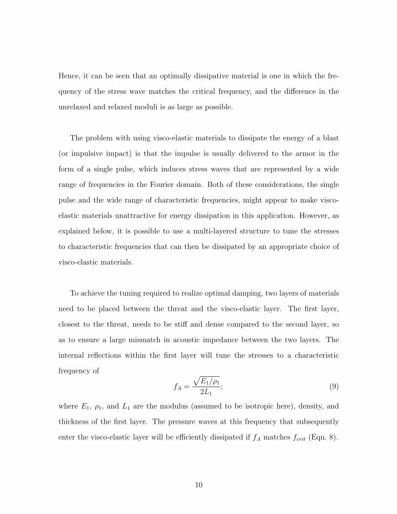
To achieve the tuning required to realize optimal damping, two layers of materials
need to be placed between the threat and the visco-elastic layer. The first layer,
closest to the threat, needs to be stiff and dense compared to the second layer, so
as to ensure a large mismatch in acoustic impedance between the two layers. The
internal reflections within the first layer will tune the stresses to a characteristic
frequency of
fA =
√E1/ρ12L1
; (9)
where E1, ρ1, and L1 are the modulus (assumed to be isotropic here), density, and
thickness of the first layer. The pressure waves at this frequency that subsequently
enter the visco-elastic layer will be efficiently dissipated if fA matches fcrit (Eqn. 8).
10

The energy dissipated in a visco-elastic material increases with the number of
loading and unloading cycles, and with their amplitude. This adds some additional
considerations to the design of multi-layered armor. First, the impedance mismatch
between the first and second layers must be just large enough to provide good tun-
ing without excessively reducing the amplitude of the stresses that eventually get
transmitted into the energy-absorbing layer. For a similar reason, to ensure a rea-
sonable amplitude of stress waves for dissipation, the impedance of the third layer
must be relatively high compared to the impedance of the second layer. Furthermore,
the need to have many stress cycles within the visco-elastic layer suggests that the
tuned frequency should be as high as possible, consistent with finding a suitable corre-
sponding visco-elastic material. The higher the frequency, the less material is needed
to dissipate the energy (for a given wave speed). The potential materials challenge
from a development perspective is that the frequencies associated with this tuning
will be in a range for which the properties of polymers have only received limited
study [72, 73, 74, 75].
It was noted from the results of the finite-element analyses described in the next
section that, in addition to fA, two other, significantly lower, characteristic frequen-
cies, fB and fC , enter the visco-elastic layer in a tuned system. These other two
frequencies have periods corresponding to the times for the tuned wave to traverse
the third and second layers, respectively. Spectral analyses of the waves in the first
element of the visco-elastic material indicated that, for a typical well-designed sys-
tem, about 45% of the impulse was carried by fA, about 40% was carried by fB, and
about 15% was carried by fC and its harmonics.
In the present implementation, we have analyzed a system with only one critical
11

frequency, so only the high-frequency, fA, component is dissipated. In principle, one
might consider implementing a design with additional visco-elastic materials, or with
a material having multiple relaxation times, to mitigate the other frequencies. How-
ever, it should be noted that, even if the lower frequencies are not dissipated, they
serve a useful purpose by transmitting some of the impulse through the armor at a
lower velocity. As discussed in Section 2, one strategy for blast and impact mitiga-
tion is to increase the transmission time so that the peak pressure (which can then
be controlled by impedance mismatch), rather than impulse, dominates the response
of the target.
5. Finite-element analysis of blast mitigation
In this paper, we used a commercial finite-element code, ABAQUS Explicit [76],
to analyze blast mitigation. In these analyses, the internal interactions within the
protected structure, between the supporting structure and the delicate target, were
not addressed. It was assumed that the characteristics of the pressure pulse that
the structure can support without damage to the target are known from a separate
analysis of the protected structure. We, therefore, compared the maximum ampli-
tude of the stress wave, Pt, and impulse, It, transmitted through the armor to an
elastic structure behind it, to the corresponding values of Po and Io of the original
pressure pulse applied to the surface of the armor. The relative ratios of Pt/Po and
It/Io were taken as the two primary measures of performance of the armor, and used
for comparisons between different designs.
The armor and the protected structure were modeled using three-dimensional,
eight-node brick elements with reduced integration. The geometry is shown in Fig. 1.
12

Figure 1: Geometry of the armor and protected structure exposed to a time-varying normal load,P (t), analyzed in the finite-element model.
The displacements along one set of xz- and xy-faces were constrained in the y- and z-
directions, respectively. The other xz- and xy-faces were traction-free. The interfaces
between the internal layers of the armor were bonded. The protected structure was
a solid, linear-elastic block. The interface between the structure and the armor was
frictionless. A pressure P (t) was applied to the external surface of the armor, along
the x-direction (Fig. 1). This pressure decayed linearly to zero from an initial value
of Po during a time to. It was verified that the major conclusions of the study were
not sensitive to this particular choice of P (t).
The peak pressure transmitted to the protected structure, Pt, was taken to be
the maximum value of the longitudinal stress at the internal surface of the armor, as
calculated from the finite-element calculations. Determining the transmitted impulse
was more complicated. As will be discussed in more detail later, two distinct types of
behavior were observed. In one type of behavior, momentum was transferred to the
structure/target system in a single broad pulse. In the other type of behavior, mo-
mentum was transferred over a large number of broad pulses separated by significant
periods of time. Owing to the time scales involved, only the impulse delivered in the
first broad pulse was considered. Therefore, rather than comparing Io to the total
13

transmitted impulse, we compared it to the effective transmitted impulse Ieff , deter-
mined by integrating the longitudinal stress at the internal surface of the armor over
the first broad pulse delivered to the structure. The calculations for the transmit-
ted impulse were verified by comparing it to the momentum of the protected structure.
Since a commercial code was used, considerable care was taken to reduce the ef-
fects of any spurious numerical artifacts to below an acceptable level of numerical
uncertainty that we indicate on our plots. For example, the default bulk-viscosity pa-
rameter was set to zero, and double-precision was used for the solutions. Additional
concerns were that the effects of the two non-dimensional groups involving the time-
step and mesh size should be no larger than the uncertainties introduced by any of the
other unspecified non-dimensional groups (see Section 6). We did this by ensuring an
adequate number of time steps and nodes for the highest frequency and shortest wave-
length of interest. To satisfy the first requirement, the highest frequency seen in any
of the three layers and its associated period were identified, and the time increment
was set to be no more than 20% of this period. To satisfy the second requirement, the
shortest wavelength in a simulation was identified, and the largest element size was
set to be no more than 20% of that wavelength. We also ensured that the Courant-
Friedriches-Lewy condition was met by setting the Courant number to 0.2. Finally,
we verified that any changes introduced in the solutions by further spacial or temporal
refinement were insignificant within the limits of the quoted error bars. Examples of
the form of the stress waves at different locations within the armor are given in Fig. 2.
14

Figure 2: An example of a spatial plot showing how the magnitudes of the stress waves vary as afunction of distance through the armor for a well-tuned system (fcrit/fA = 1), and two poorly-tunedsystems (fcrit/fA = 0.01 and 100). (b) shows a detail of (a). These plots were taken at a normalizedtime of fAt = 46. The values of the other groups are given by Ecritρ3/E2ρ2 = 1, Er/Eu = 0.001and t3/t1 = 100. The non-dimensional groups are explained in Section 6.
15
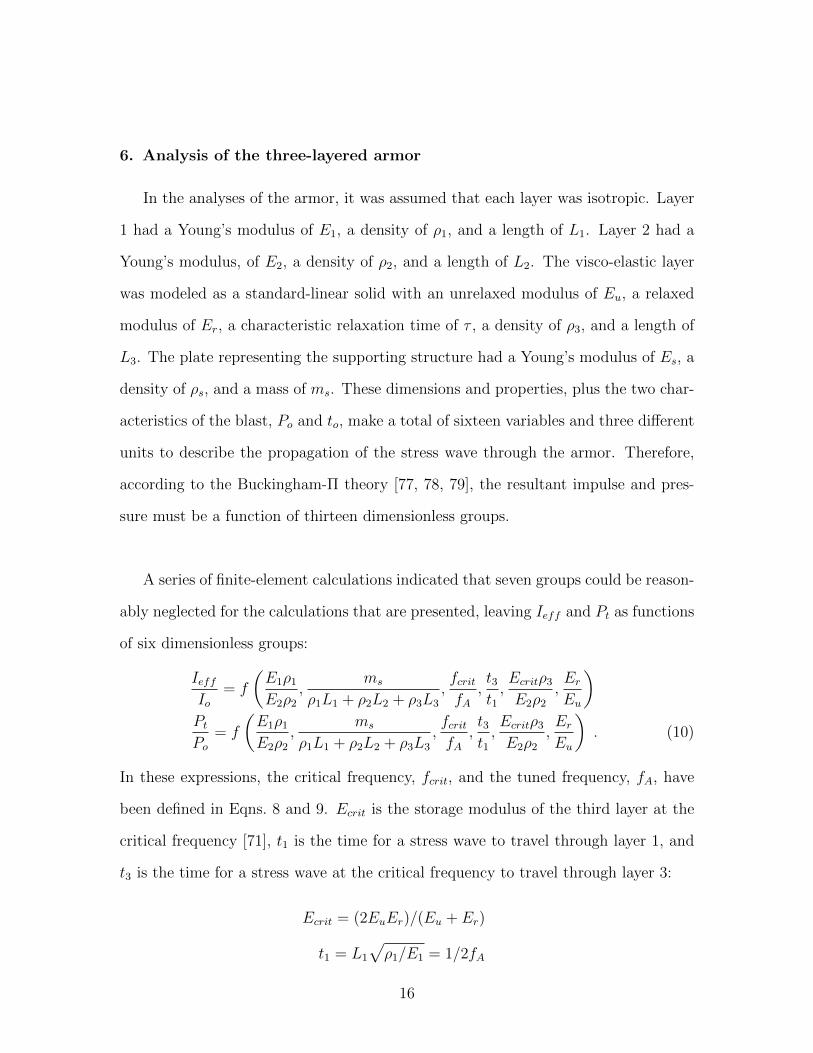
6. Analysis of the three-layered armor
In the analyses of the armor, it was assumed that each layer was isotropic. Layer
1 had a Young’s modulus of E1, a density of ρ1, and a length of L1. Layer 2 had a
Young’s modulus, of E2, a density of ρ2, and a length of L2. The visco-elastic layer
was modeled as a standard-linear solid with an unrelaxed modulus of Eu, a relaxed
modulus of Er, a characteristic relaxation time of τ , a density of ρ3, and a length of
L3. The plate representing the supporting structure had a Young’s modulus of Es, a
density of ρs, and a mass of ms. These dimensions and properties, plus the two char-
acteristics of the blast, Po and to, make a total of sixteen variables and three different
units to describe the propagation of the stress wave through the armor. Therefore,
according to the Buckingham-Π theory [77, 78, 79], the resultant impulse and pres-
sure must be a function of thirteen dimensionless groups.
A series of finite-element calculations indicated that seven groups could be reason-
ably neglected for the calculations that are presented, leaving Ieff and Pt as functions
of six dimensionless groups:
IeffIo
= f
(E1ρ1E2ρ2
,ms
ρ1L1 + ρ2L2 + ρ3L3
,fcritfA
,t3t1,Ecritρ3E2ρ2
,Er
Eu
)Pt
Po
= f
(E1ρ1E2ρ2
,ms
ρ1L1 + ρ2L2 + ρ3L3
,fcritfA
,t3t1,Ecritρ3E2ρ2
,Er
Eu
). (10)
In these expressions, the critical frequency, fcrit, and the tuned frequency, fA, have
been defined in Eqns. 8 and 9. Ecrit is the storage modulus of the third layer at the
critical frequency [71], t1 is the time for a stress wave to travel through layer 1, and
t3 is the time for a stress wave at the critical frequency to travel through layer 3:
Ecrit = (2EuEr)/(Eu + Er)
t1 = L1
√ρ1/E1 = 1/2fA
16

t3 = L3
√ρ3/Ecrit . (11)
The first non-dimensional group, E1ρ1/E2ρ2, is the square of the impedance mis-
match between the first two layers. As discussed earlier, this needs to be high enough
to ensure tuning, but low enough to make sure that the stress waves pass through
to the visco-elastic layer where they can be damped. A series of finite-element cal-
culations indicated that the optimal level for the impedance mismatch is about 70.
So, in all the calculations that follow, E1ρ1/E2ρ2 was set to a fixed value of 5,000.
The second non-dimensional group is the relative mass of the protected structure to
the mass of the armor. As indicated in Section 3, the transmitted impulse decreases
with the relative mass of the armor. Therefore, to provide a point of comparison
between the different calculations, ms/ (ρ1L1 + ρ2L2 + ρ3L3) = 1 for all calculations.
The effects of the other four important non-dimensional groups will be seen in the
results that follow. During the calculations, the remaining seven, non-critical, groups
were allowed to vary within fairly broad ranges1. The error bars shown on the figures
are the result of both numerical uncertainties and the variations of these non-critical
groups.
In the results that follow, it will be observed that there are regimes in which the
transmitted impulse appears to be less than 0.5Io: less than that expected to be
transmitted by perfectly-plastic armor. This can be explained by reference to Fig. 3,
which shows how the pressure can be transmitted to the protected structure through
widely spaced pulses. Poorly-tuned armor transmits the impulse over a single broad
10.1 < to/t1 < 10, 0.08 < L1/L2 < 10, 5 < E1/E2 < 25, 000, 7 × 10⁻⁵ < Ecrit/E2 < 60,Esρs/Ecritρ3 > 8, 000, 0.8 < ρs/ρ3 < 2, and 10−5 < Po/E1 < 0.4.
17
pulse. Good tuning and dissipation results in only some of the impulse being trans-
mitted in the first pulse before contact is lost with the protected structure; the rest
of the impulse is then transmitted when there is subsequent contact, sometimes after
multiple internal reflections within the armor. The impulse transmitted to the armor
in the initial pulse is defined as the “effective” impulse, Ieff , since the subsequent
pulses occur so much later that they will probably have no significant effect on the
target (see Appendix).
A well-tuned wave is expected to be optimally damped at fcrit/fA = 1, and the
effectiveness of the damping is expected to increase with the number of cycles that
the pressure wave experiences in the visco-elastic layer. The first concept is illus-
trated by the plots in Figs. 4 and 5 that show minima in the effective impulse and
transmitted pressure at fcrit/fA = 1. The second concept is illustrated by the plots in
Figs. 6 and 7 that show how the effective impulse and transmitted pressure decrease
as the time for the stress wave to traverse the visco-elastic layer is increased. This
travel time can be increased either by increasing the thickness of the visco-elastic
layer, or by decreasing the wave speed.
Figures 4 and 6 show that there is no significant reduction in the effective im-
pulse if Er/Eu ≥ 0.1, because there is no energy dissipation, even for well-tuned
armor. Correspondingly, the drop in the amplitude of the transmitted pressure for
Er/Eu ≥ 0.1 shown in Figs. 5 and 7 is determined only by impedance mismatch.
Finally, it will be noted from the plots in Figs. 4 and 5 that, when Er/Eu is small,
the minima are fairly broad for values of fcrit/fA > 1. This can be explained by
reference to Eqns. 6 and 8; as Er/Eu becomes smaller, tan δ exhibits a broader peak
18
Figure 3: Pressure waves at the beginning, middle, and end of the visco-elastic layer. These areshown in (a) and (b) for a well-tuned system with fA/fcrit = 1, and in (c) for a poorly-tuned systemwith fA/fcrit = 0.01. The values of the other significant groups are given by Ecritρ3/E2ρ2 = 1,Er/Eu = 0.001 and t3/t1 = 100. A detail of the stress waves for (a) is shown in (b). These figuresshow how, in a well-tuned system, the latter parts of the impulse can be transmitted to the protectedstructure in pulses separated by time intervals that are increments of 1/fB . While in a poorly-tunedsystem, the impulse gets transmitted to the protected structure over a single broad pulse.
19
Figure 4: The effective impulse is minimized after passage through a three-layer visco-elastic armorwhen fcrit/fA = 1. The transmitted impulse occurs in a single pulse for Er/Eu > 0.005. For lowervalues of Er/Eu, the impulse is transmitted in a series of pulses, so Ieff < Io/2. When Er/Eu > 0.1,there is negligible dissipation in the armor, and there is no reduction in the transmitted impulse.
Figure 5: A significant reduction in the transmitted peak pressure can be achieved with a well-tuned,three-layer visco-elastic armor. The reduction in this peak pressure is increased as the ratio Er/Eu
is reduced. When Er/Eu > 0.1, there is negligible dissipation in the armor, and any reduction inthe pressure pulse occurs only because of impedance mismatch.
20
Figure 6: For a well-tuned three-layer armor, the effective impulse drops with the time taken for thestress wave to traverse the visco-elastic layer.
Figure 7: For a well-tuned three-layer armor, the maximum amplitude of the transmitted pressuredrops with the time taken for the stress wave to traverse the visco-elastic layer, since this allows anincrease in energy dissipation.
21

skewed to fcrit/fA > 1. As will be discussed later, this may have significant practical
importance from a design perspective in reducing the sensitivity of the performance
of the armor to variations in operating conditions.
7. Comparison with elastic and plastic designs
Armor consisting of only elastic layers will transmit an impulse equal to the ini-
tial impulse, if it has the same mass as the supporting structure. The transmitted
pressure in such a system can be controlled using impedance mismatch between the
two layers. Furthermore, a second layer with a low impedance could increase the
time-scale for the transmission of the impulse sufficiently to make control of the pres-
sure amplitudes a more important design consideration than control of impulse. For
cheap, low-performance armor and helmets, this approach certainly provides a possi-
ble design strategy. Whether it is suitable or not, would depend on the application.
Armor containing a plastic layer to dissipate energy would result in the impulse
always being transmitted over a single broad pulse. If the armor and supporting
structure have equal mass, the magnitude of the transmitted impulse would be in
the range Io to 0.5Io, depending on how efficiently the armor dissipates energy. Fur-
thermore, although energy can be as dissipated with plasticity as efficiently as with
visco-elasticity, the use of plastic armor is limited to a single incident.
8. Conclusions
The stress induced within a target that is part of a dynamical system, such as
the brain within a skull, is determined either by the directly transmitted pressure,
22

or by the transmitted impulse. The relative importance of the two depends on the
duration of the pressure wave impinging upon the protected structure, compared to
the characteristic time of the dynamic response of the system. The design of any
armor used as protection from blast in military applications, or by impact in sport-
ing or industrial applications, needs to consider both of these time scales. Armor
can mitigate both the pressure and the impulse. It can also change the time scale
over which a pressure wave is transmitted, so as to move the design away from one in
which impulse needs to be mitigated, to one in which the pressure needs to be limited.
Impedance mismatch can control the transmitted pressure. Energy dissipation mech-
anisms can mitigate the transmitted impulse. Dispersion (and impedance mismatch)
can increase the interaction time between the supported structure and the threat, so
as to change the damage regime from one controlled by impulse to one controlled by
pressure.
In this paper we have proposed that visco-elastic polymers can be used for protec-
tion over multiple events. However, for this concept to be realized, it is necessary for
the stress waves traveling through the armor to do so at frequencies corresponding to
appropriate dissipative molecular transitions in the polymers. Typically, the energy
of the stress waves induced by blast or impact is broadly distributed over multiple
frequencies. Therefore, this energy must be tuned to a narrow spectrum before it can
be optimally dissipated by the polymer. Here, it is proposed to do this through a
multi-layer design in which the outer layers tune the stress waves to match the critical
damping frequency of the inner visco-elastic layer. As a high-frequency stress wave
travels through this visco-elastic layer, it undergoes multiple loading-unloading cycles
which can result in significant energy dissipation over a short duration.
23

A finite-element analysis of this concept has illustrated several important con-
straints on the design. The outer layer needs to have a high acoustic impedance
compared to its neighbor, so that the wave can be tuned by multiple reflections at
the interface between the two layers. Although, for reasons discussed in Section 6,
the impedance mismatch must not be so high that the stress waves is transmitted
inefficiently through successive layers. The numerical simulations suggest that an
impedance mismatch of about 70, is optimal. Typically, one would expect to use
an outer layer with a relatively high modulus; but it is recognized that the outer
layer may also have to serve other functional purposes, such as resistance to ballistic
penetration. It is also recognized that in sports applications involving impact, more
compliant helmets may increase the characteristic time for transmission of an impulse,
and move the design space to a regime where dissipation of energy is less critical.
There are two significant constraints on the material properties of the visco-elastic
layer used for energy dissipation. First, it needs to have a very low ratio of the re-
laxed modulus to the unrelaxed modulus. This will result in a high value of tan δ
at a critical frequency that matches the tuned frequency from the first layer. Sec-
ond, for realistic thicknesses of the outer layer, the critical frequency of the polymer
will need to be quite high. For example, if the modulus of the outer layer is of the
order of 1-10 GPa, its density is 1000 kg·m−3, and its length is 5 mm, the critical
frequency that needs to be damped will be about 100-300 kHz. This leads to some
experimental challenges in identifying and designing suitable polymers, for it is far
above the range of frequencies at which polymers are typically investigated. However,
ultrasonic methods [72] and dielectric analyses [75] have been used to measure tan δ
and the storage and loss moduli in the MHz range.
24

The glass transition is a possible energy-loss peak to explore for these purposes [73,
74], and it is instructive to consider what value of glass-transition temperature, Tg,
measured in the 1 Hz range, might correspond to a glass transition in the 200 kHz
range at an operating temperature of To. This can be estimated from the WLF
equation [80], for a shift factor of 2× 10⁵:
log(2× 10⁵) =17.5(To − Tg)52 + To − Tg
(12)
This expression results in a glass transition temperature measured at 1 Hz which is
about 23 oC below the operating temperature. For example, if the inside of a helmet
is maintained at body temperature, the required glass-transition temperature would
be about 14 oC. However, there will obviously be a range of operating temperatures,
depending on the external environment. Fortunately, the analysis (Figs. 4 and 5)
shows that the efficacy of the proposed design is relatively insensitive to fcrit, pro-
vided that fcrit/fA > 1 and Er/Eu is very small. In practice, this puts an upper
bound on Tg of about 20-30 oC below the lowest temperature that the armor will ex-
perience in service. Higher temperatures, within a reasonable range, will result in the
system being within the plateau where the response is not very sensitive to fcrit/fA.
In conclusion, this result would seem to indicate that there is plenty of flexibility to
use even higher tuning frequencies than 200kHz, since the required value of Tg is not
particularly low.
9. Acknowledgements
This work has been supported by the ONR under grant ONR N00014-10-1-415.
The authors are grateful for many helpful discussions with Prof. A. M. Waas during
the course of this project.
25

10. References
[1] G.I. Taylor. Pressure and impulse of submarine explosion waves on plates. In
G.K. Batchelor, editor, The Scientific Papers of Sir Geoffrey Ingram Taylor, Vol-
ume III: Aerodynamics and the Mechanics of Projectiles and Explosions, pages
287–303. Cambridge University Press, Cambridge, UK, 1963.
[2] N. Kambouchev, R. Radovitzky, and L. Noels. Fluid-structure interaction effects
in the dynamic response of free-standing plates to uniform shock loading. Journal
of Applied Mechanics, 74(5):1042–1045, 2007.
[3] N. Kambouchev, L. Noels, and R. Radovitzky. Nonlinear compressibility effects
in fluid-structure interaction and their implications on the air-blast loading of
structures. Journal of Applied Physics, 100(063519):1–12, 2006.
[4] N. Kambouchev, L. Noels, and R. Radovitzky. Numerical simulation of the fluid-
structure interaction between air blast waves and free-standing plates. Computers
& Structures, 85(11-14):923–931, 2007.
[5] P.D. Smith and J.G. Hetherington. Blast and Ballistic Loading of Structures.
Butterworth Heinemann, Burlington, MA, USA, 1994.
[6] M.M. Swisdak. Explosion effects and properties: Part II - Explosion effects
in water. Technical Report NSWCIWOL TR 76-116, Naval Surface Weapons
Center, White Oak, Silver Spring, MD 20910, USA, 1978.
[7] M.F. Ashby, A.G. Evans, N.A. Fleck, L.J. Gibson, J.W. Hutchinson, and H.N.G.
Wadley. Metal Foams: A Design Guide. Butterworth Heinemann, Woburn, MA,
USA, 2000.
26

[8] Z. Xue and J.W. Hutchinson. A comparative study of impulse-resistant metal
sandwich plates. International Journal of Impact Engineering, 30(10):1283–1305,
2004.
[9] A.J. Wang and H.G. Hopkins. On the plastic deformation of built-in circular
plates under impulsive load. Journal of the Mechanics and Physics of Solids,
8:22–87, 1954.
[10] A.L. Florence. Clamped circular rigid-plastic plates under central blast loading.
International Journal of Solids Structures, 2:319–335, 1966.
[11] P.S. Symonds and T. Wierzbicki. Membrane mode solutions for impulsively
loaded circular plates. Journal of Applied Mechanics, 46(1):58–64, 1979.
[12] N. Jones. A theoretical study of the dynamic plastic behaviour of beams and
plates with finite-deflections. International Journal of Solids and Structures,
7(8):1007–1029, 1971.
[13] N. Jones. Structural Impact. Cambridge University Press, Cambridge, UK, 2nd
edition, 1989.
[14] Z. Xue and J.W. Hutchinson. Preliminary assessment of sandwich plates subject
to blast loads. International Journal of Mechanical Sciences, 45(4):687–705,
2003.
[15] A.V. Amirkhizi, J. Isaacs, J. McGee, and S. Nemat-Nasser. An experimentally-
based viscoelastic constitutive model for polyurea, including pressure and tem-
perature effects. Philosophical Magazine, 86(36):5847–5866, 2006.
[16] M.R. Amini, A.V. Amirkhizi, and S. Nemat-Nasser. Numerical modeling of re-
27

sponse of monolithic and bilayer plates to impulsive loads. International Journal
of Impact Engineering, 37(1):90–102, 2010.
[17] M.R. Amini, J. Isaacs, and S. Nemat-Nasser. Investigation of effect of polyurea
on response of steel plates to impulsive loads in direct pressure-pulse experiments.
Mechanics of Materials, 42(6):628–639, 2010.
[18] M.R. Amini, J. Isaacs, and S. Nemat-Nasser. Experimental investigation of re-
sponse of monolithic and bilayer plates to impulsive loads. International Journal
of Impact Engineering, 37(1):82–89, 2010.
[19] V.S. Deshpande, A. Heaver, and N.A. Fleck. An underwater shock simulator.
Proceedings of the Royal Society A, 462(2067):1021–1041, 2006.
[20] N.A. Fleck and V.S. Deshpande. The resistance of clamped sandwich beams to
shock loading. Journal of Applied Mechanics, 71(3):1–16, 2004.
[21] E. Ferri, E. Antinucci, M.Y. He, J.W. Hutchinson, F.W. Zok, and A.G. Evans.
Dynamic buckling of impulsively loaded prismatic cores. Journal of Mechanics
of Materials and Structures, 1(8):1345–1365, 2006.
[22] S. Lee, F. Barthelat, J.W. Hutchinson, and H.D. Espinosa. Dynamic failure of
metallic pyramidal truss core materials: Experiments and modeling. Interna-
tional Journal of Plasticity, 22(11):2118–2145, 2006.
[23] D.D. Radford, G.J. McShane, V.S. Deshpande, and N.A. Fleck. Dynamic com-
pressive response of stainless-steel square honeycombs. Journal of Applied Me-
chanics, 74(4):658–667, 2007.
[24] Z. Xue and J.W. Hutchinson. Crush dynamics of square honeycomb sandwich
28

cores. International Journal for Numerical Methods in Engineering, 65(13):2221–
2245, 2006.
[25] M.T. Tilbrook, D.D. Radford, V.S. Deshpande, and N.A. Fleck. Dynamic crush-
ing of sandwich panels with prismatic lattice cores. International Journal of
Solids and Structures, 44(18-19):6101–6123, 2007.
[26] G.J. McShane, S.M. Pingle, V.S. Deshpande, and N.A. Fleck. Dynamic buckling
of an inclined structure. International Journal of Solids and Structures, 49(19-
20):2830–2838, 2012.
[27] V.S. Deshpande and N.A. Fleck. High strain rate compressive behaviour of
aluminium alloy foams. International Journal of Impact Engineering, 24(3):277–
298, 2000.
[28] P.J. Tan, S.R. Reid, J.J. Harrigan, Z. Zou, and S. Li. Dynamic compressive
strength properties of aluminium foams. Part I: Experimental data and observa-
tions. Journal of the Mechanics and Physics of Solids, 53(10):2174–2205, 2005.
[29] A. Vaziri and J.W. Hutchinson. Metal sandwich plates subject to intense air
shocks. International Journal of Solids and Structures, 44(6):2021–2035, 2007.
[30] F. Zhu, Z. Wang, G. Lu, and G. Nurick. Some theoretical considerations on the
dynamic response of sandwich structures under impulsive loading. International
Journal of Impact Engineering, 37(6):625–637, 2010.
[31] G.J. Dvorak and A.P. Suvorov. Protection of sandwich plates from low-velocity
impact. Journal of Composite Materials, 40(15):1317–1331, 2005.
[32] Y.A. Bahei-El-Din, G.J. Dvorak, and O.J. Fredricksen. A blast-tolerant sandwich
29

plate design with a polyurea interlayer. International Journal of Solids and
Structures, 43(25-26):7644–7658, 2006.
[33] Y.A. Bahei-El-Din and G.J. Dvorak. Wave propagation and dispersion in sand-
wich plates subjected to blast loads. Mechanics of Advanced Materials and Struc-
tures, 14(6):465–475, 2007.
[34] A. Yehia, Y.A. Bahei-El-Din, and G.J. Dvorak. Enhancement of blast resistance
of sandwich plates. Composites B, 39(1):120–127, 2008.
[35] S. A. Tekalur, A. Shukla, and K. Shivakumar. Blast resistance of polyurea based
layered composite materials. Composite Structures, 84(3):271–281, 2008.
[36] N. Gardner, E. Wang, P. Kumar, and A. Shukla. Blast mitigation in a sandwich
composite using graded core and polyurea interlayer. Experimental Mechanics,
52(2):119–133, 2011.
[37] M.Z. Hassan, Z.W. Guan, W.J. Cantwell, G.S. Langdon, and G.N. Nurick. The
influence of core density on the blast resistance of foam-based sandwich struc-
tures. International Journal of Impact Engineering, 50:9–16, 2012.
[38] G.E. Morgan. US Patent 3609764 - Energy absoring and sizing means for helmets,
1971.
[39] V. Ponomarev and I. Ponomaryova. US Patent 7017705 - Blast compression
wave absorbing device, 2006.
[40] S. Zhuang, G. Ravichandran, and D.E. Grady. An experimental investigation
of shock wave propagation in periodically layered composites. Journal of the
Mechanics and Physics of Solids, 51(2):245–265, 2003.
30
[41] V.F. Nesterenko. Shock (blast) mitigation by “soft” condensed matter. In Mate-
rials Research Society Symposium Proceedings, volume PROC-759-MM4.3, 2002.
[42] W.F. Hartman, B.A. Boughton, and M.E. Larsen. Blast mitigation capabilities of
aqueous foam. Technical Report SAND2006-0533, Sandia National Laboratories,
Albuquerque, NM 87185, USA, 2006.
[43] R.M. Allen, D.J. Kirkpatrick, A.W. Longbottom, A.M. Milne, and N.K. Bourne.
Experimental and numerical study of free-field blast mitigation. AIP Conference
Proceedings, 706(1):823–826, 2004.
[44] B.E. Gelfand, M.V. Silnikov, A.I. Mikhailin, and A.V. Orlov. Attenuation of
blast overpressures from liquid in an elastic shell. Combustion, Explosion and
Shock Waves, 37(5):607–612, 2001.
[45] A. Leonard and C. Daraio. Stress wave anisotropy in centered square highly
nonlinear granular systems. Physical Review Letters, 108(21):1–4, 2012.
[46] V.F. Nesterenko. Dynamics of Heterogeneous Materials. Springer-Verlag, New
York, NY, USA, 2001.
[47] C. Daraio, V.F. Nesterenko, E. Herbold, and S. Jin. Energy trapping and shock
disintegration in a composite granular medium. Physical Review Letters, 96(5):1–
4, 2006.
[48] B.R. Schimizze, S.F. Son, R. Goel, A.P. Vechart, and L.R. Young. An experi-
mental and numerical study of blast induced shock wave mitigation in sandwich
structures. Applied Acoustics, 74(1):1–9, 2013.
[49] H.N.G. Wadley, K.P. Dharmasena, M.Y. He, R.M. McMeeking, A.G. Evans,
31
T. Bui-Thanh, and R. Radovitzky. An active concept for limiting injuries caused
by air blasts. International Journal of Impact Engineering, 37(3):317–323, 2010.
[50] M. Grujicic, G. Arakere, and T. He. Material-modeling and structural-mechanics
aspects of the traumatic brain injury problem. Multidiscipline Modelling in Ma-
terials and structures, 6:335–363, 2010.
[51] M. Grujicic, W.C. Bell, B. Pandurangan, and T. He. Blast-wave impact-
mitigation capability of polyurea when used as helmet suspension-pad material.
Materials and Design, 31(9):4050–4065, 2010.
[52] L. Zhang, R. Makwana, and S. Sharma. Brain response to primary blast wave us-
ing validated finite element models of human head and advanced combat helmet.
Frontiers in neurology, 4(88):1–12, 2013.
[53] S.G. Ganpule, L. Gu, A.L. Alai, and N. Chandra. Role of helmet in the mechanics
of shock wave propagation under blast loading conditions. Computer Methods in
Biomechanics and Biomedical Engineering, 15(11):1233–1244, 2012.
[54] D. Stewart, L.R. Young, R. Goel, G. Christou, and M.D. Gilchrist. Evaluating
the performance of helmet linings incorporating fluid channels. Journal of ASME
International, 7(10):1–7, 2010.
[55] J. Kimberley, J. Lambros, I. Chasiotis, J. Pulskamp, R. Polcawich, and
M. Dubey. Mechanics of energy transfer and failure of ductile microscale beams
subjected to dynamic loading. Journal of the Mechanics and Physics of Solids,
58(8):1125–1138, 2010.
[56] S.J. Stritch. Shearing of nerve fibres as a cause of brain damage due to head
injury: A pathological study of twenty cases. Lancet, 278:443–448, 1961.
32

[57] N.C. Nevin. Neuropathological changes in the white matter following head injury.
Journal of Neuropathology and Experimental Neurology, 26:77–84, 1967.
[58] V.E. Johnson, W Stewart, and Smith D.H. Axonal pathology in traumatic brain
injury. Experimental Neurology, 246:35–43, 2013.
[59] A.H.S. Holbourn. Mechanics of head injuries. Lancet, 242:438–441, 1943.
[60] E.S. Gurdjian, H.R. Lissner, F.R. Latimerr, B.F. Haddad, and J.E. Webster.
Quantitative determination of acceleration and intercranial pressure in experi-
mental head injury. Neurology, 3:417–423, 1953.
[61] W.N. Hardy, T.B. Khalil, and A.I King. Literature review of head injury biome-
chanics. International Journal of Impact Engineering, 15(4):561–586, 1994.
[62] J. S. Ruan and P. Prasad. Coupling of a finite element human head model with
a lumped parameter hybrid III dummy model: Preliminary results. Journal of
Neurotrauma, 12(4):725–734, 2007.
[63] L.E. Goldstein, A.M. Fisher, C.A. Tagge, X.L. Zhang, L. Velisek, J.A. Sullivan,
C. Upreti, J.M. Kracht, M. Ericsson, M.W. Wojnarowicz, C.J. Goletiani, G.M.
Maglakelidze, N. Casey, J.A. Moncaster, O. Minaeva, R.D. Moir, C.J. Nowinski,
R.A. Stern, R.C. Cantu, J. Geiling, J.K. Blusztajn, B.L. Wolozin, T. Ikezu,
T.D. Stein, A.E. Budson, N.W. Kowall, D. Chargin, A. Sharon, S. Sudad, G.F.
Hall, W.C. Moss, R.O. Cleveland, R.E. Tanzi, P.K. Stanton, and A.C. McKee.
Chronic traumatic encephalopathy in blast-exposed military veterans and a blast
neurotrauma mouse model. Science Translational Medicine, 4(134):1–14, 2012.
[64] J.M. Meythaler, J.D. Peduzzi, E. Eleftheriou, and T.A. Novack. Current con-
33

cepts: Diffuse axonal injuryassociated traumatic brain injury. Archives of Phys-
ical Medicine and Rehabilitation, 82(10):1461–1471, 2001.
[65] H.W. Henn. Crash tests and head injury criteria. Teaching Mathematics and its
Applications, 17(4):162–170, 1998.
[66] S.P. Broglio, J.T. Eckner, T. Surma, and J.S. Kutcher. Post-concussion cognitive
declines and symptomatology are not related to concussion biomechanics in high
school football players. Journal of Neurotrauma, 28(10):1–8, 2011.
[67] S.P. Broglio, B. Schnebel, J.J. Sosnoff, S. Shin, X. Fend, X. He, and J. Zimmer-
man. Biomechanical properties of concussions in high school football. Medicine
and Science in Sports and Exercise, 42(11):2064–2071, 2010.
[68] R.M. Greenwald, J.T. Gwin, J.J. Chu, and J.J. Crisco. Head impact severity
measures for evaluating mild Traumatic Brain Injury risk explosure. Neuro-
surgery, 62(4):789–798, 2008.
[69] H. Kolsky. Stress Waves in Solids. Dover Publications, New York, NY, USA,
2nd edition, 2012.
[70] R.C. Hibbeler. Engineering Mechanics: Statics and Dynamics. Macmillan Pub-
lishing Company, New York, NY, USA, 5th edition, 1989.
[71] A.S. Wineman and K.R. Rajagopal. Mechanical Response of Polymers: An
Introduction. Cambridge University Press, Cambridge, UK, 2000.
[72] I. Alig, F. Stieber, and S. Wartewig. Ultrasonic examination of the dynamic
glass transition in amorphous polymers. Journal of Non-Crystalline Solids, 131-
133:808–811, 1991.
34
[73] C.M. Rowland and R. Casalini. Effect of hydrostatic pressure on the viscoelastic
response of polyurea. Polymer, 48:5747–5752, 2007.
[74] R.B. Bogoslovov, C.M. Rowland, and R.M Gamache. Impact-induced glass tran-
sition in elastomeric coatings. Applied Physics Letters, 90(221910):1–3, 2007.
[75] A.J. Hsieh, T.L. Chantawansri, W. Hu, K.E. Strawhecker, D.T. Casem, J.K. Elia-
son, K.A. Nelson, and E.M. Parsons. New insight into microstrcuture-mediated
segmental dynamics in select model poly(urethane urea) elastomers. Polymer,
55:1883–1892, 2014.
[76] ABAQUS version 6.8-1, User Documentation, Dassault Systems, 2008.
[77] J.W. Srutt. On the equation of the stability of the flow of liquids. Philosophical
Magazine, 34:59–70, 1892.
[78] A Vaschy. Sur les lois de similitude en physique. Annales Telegraphiques, 19:25–
28, 1892.
[79] E. Buckingham. On physically similar systems: illustrations of the use of dimen-
sional equations. Physical Reviews, 4(4):345–376, 1914.
[80] M.L. Williams, R.F. Landel, and L.D. Ferry. The temperature dependence of
relaxation mechanisms in amorphous polymers and other glass-forming liquids.
Journal of the American Chemical Society, 77(14):3701–3707, 1955.
[81] D. Denny-Brown and W.R. Russell. Experimental cerebral concussion. Brain,
64(2-3):93–164, 1941.
[82] MATLAB SIMULINK R2011a, MathWorks, 2011.
35
Appendix A.
There is a general tendency in the brain injury literature to measure the accelera-
tion of the head as a proxy for the stresses acting on the brain [63, 64, 65, 66, 67, 68].
However, it was recognized more than 70 years ago [59] that this is valid only for
impacts of long duration. For short impacts and blasts, it is the change in velocity of
the head that indicates the level of the stresses in the brain. The head is a complex
dynamical system, so the force transmitted to the brain cannot simply be taken to be
the force applied to the skull. The purpose of this Appendix is to use a very simple
dynamical system to illustrate this point, since identifying the correct mechanics is
crucial for evaluating design concepts for armor.
As shown in Fig. A.1, a delicate target supported by a structural support is mod-
eled as two point masses coupled by two springs. The structural support is repre-
sented by a mass m1 that is attached to a rigid foundation by a spring of stiffness k1.
The force pulse transmitted from the blast, either directly or as modified by passage
through the armor, F (t), is applied to this structural support. In a simple model of
the head, this structural support is the skull, and the spring represents the stiffness
of the neck. The importance of this spring has been demonstrated experimentally by
showing that bracing the neck decreases the severity of brain damage [63, 81]. The
delicate target is represented by a mass m2 that is attached to the structural support
by a spring of stiffness k2. For example, in a simple model of the head, the target is
the brain, and the spring represents the cerebrospinal fluid.
The load that can cause damage to the target is given by
F2(t) = k2[x1 − x2] = m2x2 (A.1)
36

Figure A.1: Dynamic model of a structural support of mass m1 attached to a rigid foundation by aspring of stiffness k1, and coupled to a delicate target of mass m2 through a spring of stiffness k2.A pressure force F (t) is transmitted to the structure either directly from the blast, or through thearmor.
where x2 is the displacement of the target, and x1 is the displacement of the structure
(Fig. A.1). The relationship between the force imposed on the structure, F (t), and
the force acting on the target, F2(t), is given by
F2(t) = F (t)− [m1x1 + k1x1] (A.2)
A calculation of the pressure that acts on the target is obtained by solving these two
equations, subject to an assumption that the structure and target are assumed to
be initially at rest (x1 = x2 = x1 = x2 =0), and the transmitted force is a decaying
triangular pulse with a peak force Ft and a duration of tt.
A non-dimensional analysis of this problem indicates that the maximum force
acting on the target and on the supporting structure are both of the form
Pimax
Pt
= f
(m1
m2
,k1k2,
√k2m2
tt
), (A.3)
where i = 1 indicates the supporting structure and i = 2 indicates the delicate target.
A MATLAB SIMULINK [82] calculation was performed to show how F1max and F2max
vary with√k2/m2tt for a range of masses and spring constants.
37

Figure A.2: Maximum pressure exerted on the structure, F1max/Ft, and on the delicate target,
F2max/Ft, as a function of normalized time,
√k2/m2tt. The maximum pressure on the structure
is relatively constant and approximately equal to the amplitude of the transmitted pressure. Themaximum pressure on the target depends on the transmitted impulse when the transmitted pulse isshorter than the natural period of the target. It depends on the amplitude of the transmitted pressureonly when the pulse is longer than the natural period of the target.
Figure A.2 shows how the maximum force acting on the supporting structure is
relatively constant and approximately equal to Pt. This is what would be measured
by placing an accelerometer on the supporting structure. However, it can also be seen
from this figure that the maximum force on the target depends on the transmitted im-
pulse when the duration of the pulse is shorter than the natural period of the target.
The maximum force on the target only depends on the amplitude of the transmit-
ted force when the duration of the pulse is longer than the natural period of the target.
38

Although this is a relatively simple dynamical model, there are several important
conclusions about protecting targets from damage arising from blast or impact. The
first is that the maximum force on the target does not necessarily correlate with the
maximum force applied to the structure. A practical implication of this is that a
simple measurement of maximum acceleration of a skull may give no indication of
the force that a brain experiences. Acceleration measurements are useful as part of
a complete time-history record. The second is that the correct protective strategy
depends on the duration of the blast or impact compared to the natural frequency
of the target one is trying to protect. If the duration of the impact is long, then it
is the amplitude of the transmitted pressure that has to be reduced. This can be
done by mismatch of impedance. If the duration of the impact is short, then it is the
transmitted impulse that has to be minimized.
39