design of cold-formed stainless steel lipped channel ... · design of cold-formed stainless steel...
TRANSCRIPT

Design of cold-formed stainless steel lipped channel-
sections with web openings subjected to web crippling
under End-One-Flange loading condition
Amir M. Yousefi1, James B.P. Lim*1, Asraf Uzzaman2, Ying Lian3, G. Charles Clifton1, Ben Young4
1Department of Civil and Environmental Engineering, The University of Auckland,
New Zealand 2 Department of Mechanical and Aerospace Engineering, The University of Strathclyde,
75 Montrose Street, Glasgow G1 1XJ, UK 3 SPACE, David Keir Building, Queen’s University, Belfast, BT9 5AG, UK
4 Department of Civil Engineering, The University of Hong Kong, Pokfulam Road,
Hong Kong
(Received: ; Revised: ; Accepted: )
Abstract: This paper presents a numerical investigation on the web
crippling strength of cold-formed stainless steel lipped channel-sections with
circular web openings under end-one-flange (EOF) loading condition. In
order to take into account the influence of the circular web openings, a
parametric study involving 1,992 finite element analyses was performed,
covering duplex EN1.4462, austenitic EN1.4404 and ferretic EN1.4003
stainless steel grades; from the results of the parametric study, strength
reduction factor equations are proposed. The web crippling strengths
predicted by the reduction factor equations are first compared to the
strengths calculated using the equations recently proposed for cold-formed
carbon steel lipped channel-sections. It is demonstrated that the strength
reduction factor equations proposed for cold-formed carbon steel are
unconservative for the stainless steel grades by up to 7%. Unified strength
reduction factor equations are then proposed that can be applied to all three
stainless steel grades.
Key words: Cold-formed stainless steel, Lipped channel-section, Web crippling, Finite element
analysis, Strength reduction factor.

Nomenclature
A Web opening ratio;
a Diameter of circular web opening;
bf Overall flange width of section;
bl Overall lip width of section;
COV Coefficient of variation;
d Overall web depth of section;
E Young’s modulus of elasticity;
h Depth of the flat portion of web;
L Length of the specimen;
N Length of the bearing plate;
PASCE Nominal web crippling strength obtained from American Code;
PAS/NZS Nominal web crippling strength obtained from Australian/New Zealand Code;
PFEA Web crippling strength per web predicted from finite element (FEA);
PBS Nominal web crippling strength obtained from British Code;
PEuro Nominal web crippling strength obtained from Euro Code;
Pm Mean value of analysed-to-predicted load ratio;
R Reduction factor;
RP Proposed reduction factor;
ri Inside corner radius of section;
θ Angle between web and bearing surface
t Thickness of section;
VP Coefficient of variation of Analysed-to-predicted load ratio;
x Horizontal clear distance of the web openings to the near edge of the bearing plate;
β Reliability index;

1 Introduction
Cold-formed stainless steel sections increasingly are been used in the construction
industry, for both architectural as well as structural applications (Nethercot et. al. 2011,
Theofanous and Gardner 2011, Kiymaz and Seckin 2014) and the use of web openings in
such sections is becoming increasingly popular (Lawson et. al. 2015) (see Figure 1). Such
openings, however, result in the sections being more susceptible to web crippling as a form
of localized buckling, especially under concentrated loads applied to the bearing flange in
the vicinity of the openings.
The authors have recently proposed strength reduction factor equations for the web
crippling strength of cold-formed stainless steel lipped channel-sections with circular web
openings under the interior-one-flange (IOF) loading condition (Yousefi et al. 2016). The
equations covered three stainless steel grades: duplex grade EN 1.4462; austenitic grade EN
1.4404 and ferritic grade EN 1.4003. Other than Yousefi et al. (2016), no previous research
has considered the web crippling strength of cold-formed stainless steel lipped channel-
sections with circular web openings under either of the one or two-flange loading conditions.
The work extended that of Lian et al. (2016a,b) considering cold-formed stainless steel
instead of cold-formed carbon steel. Conducting a parametric study of 2,218 cold-formed
stainless steel lipped channel-sections with various dimensions and thicknesses, the strength
reduction factor equations proposed by Lian et al. (2016a,b) were shown to be conservative
by 2% for the duplex grade and around 9% for the austenitic and ferritic grades.
For cold-formed carbon steel with circular web openings, Lian et al. (2016c,d) have
considered the end-one-flange (EOF) loading condition. The work of Lian et al. (2016c,d)
was a continuation of the work of Uzzaman et al. (2012a,b,c, 2013), who considered the
two-flange loading condition. For cold-formed stainless steel lipped channel-sections
without openings, only Kroyink et al. (1996) has considered the web crippling strength.
Zhou and Young (2006, 2007, 2008, 2013) have considered the web crippling strength of
cold-formed stainless steel tubular sections; Keerthan and Mahendran (2012) and Keerthan
et. al. (2014) considered the web crippling strength of hollow flange channel beams.
Research by Lawson et al. (2015), while concerned with circular web openings, focussed on
the bending strength of the sections and not on the web crippling strength under
concentrated loads.
This paper considers the case of the web crippling strength of cold-formed stainless
steel lipped channel-sections under the end-one-flange (EOF) loading condition (see Figures
2 and 3) and applicability of the proposed equations by Lian et al. (2016c,d) to three
stainless steel grades, namely the duplex grade EN 1.4462; austenitic grade 1.4404 and
ferritic grade 1.4003. Typical stress-strain curves for the three grades were taken from Chen
and Young (2006) and Arrayago et. al. (2015).
2 Experimental investigation and finite element modelling
For cold-formed carbon steel, Lian et al. (2016c,d) recently conducted 74 end-one-
flange (EOF) laboratory tests on lipped channel-sections with circular web openings
subjected to web crippling (see Figure 3). Figure 4 shows the definition of the symbols used
to describe the dimensions of the cold-formed carbon steel lipped channel-sections
considered in the test programme. The laboratory tests were used to validate a non-linear
geometry elasto-plastic finite element model in ABAQUS (2014), which was then used for a
parametric study, from which design recommendations are proposed in the form of strength
reduction factor equations, relating the loss of strength due to the holes to the strength of the
web without openings. The size of the circular web openings was varied in order to
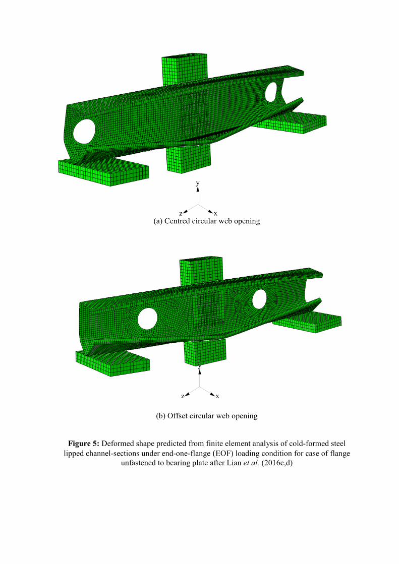
investigate the effect of the web opening size on the web crippling strength. Full details of
both the laboratory tests and finite element models (see Figure 5) can be found in Lian et al.
(2016c,d).
The models have been labeled such the nominal dimension of the model and the length
of the bearing plate as well as the ratio of the diameter of the circular web openings to the
depth of the flat portion of the webs (a/h) can be determined from the labeling system. As an
example, the label “142-N100-A0.2-FR” means the following. The first notation is the
nominal depth of the models in millimeters. The notation ''N100'' indicates the length of
bearing in millimeters (i.e. 100 mm). The notation ''A0.2'' indicates the ratio of the diameter
of the openings to the depth of the flat portion of the webs (a/h) and are one of 0.2, 0.4, 0.6
and 0.8 (i.e. A0.2 means a/h = 0.2; A0.4 means a/h = 0.4 etc). Plain lipped channel-sections
(i.e. without circular web openings) are denoted by ''A0''. The flange unfastened and fastened
cases are identified as ''FR'' and ''FX'', respectively.
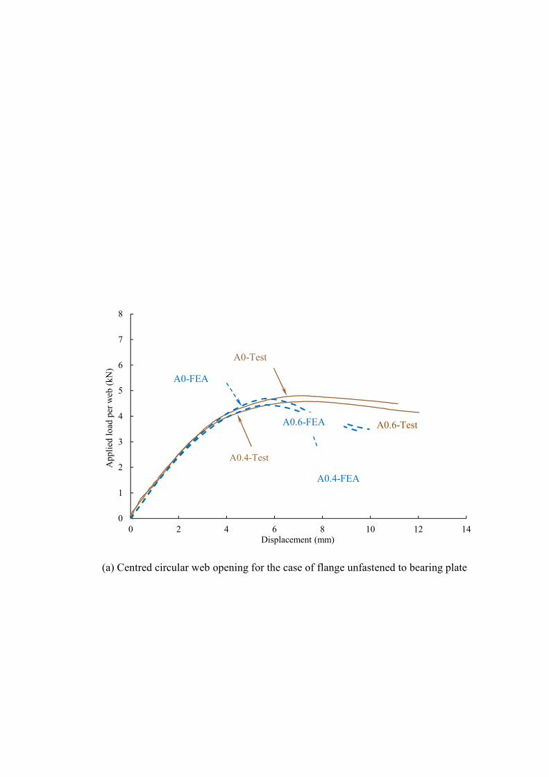
Figure 6 compares the experimental and numerical load-displacement curves for a
cold-formed carbon steel lipped channel-section, 142×60×13-t1.3-N100-FR, covering the
cases both with and without the circular web openings. As can be seen, there is good
agreement between the failure loads of the tested specimens and the finite element results.
While there is a difference in the post-ultimate range of the load-displacement curves, where
larger displacements were found in the tests compared with the numerical predictions, this
difference can be attributed to the fact that in the finite element model linear cartesian
connector elements were used to simulate bolt-hole elongation instead of physically
modelling the bolts. The stiffness of the connector elements was 10 kN/mm, which Lim and
Nethercot (2004a,b) suggest would be suitable. In addition, further displacement in the post-
ultimate range of the load-displacement curves can be attributed to slip between the channel
sections and the test rig, which was observed in the laboratory tests.

For cold-formed stainless steel lipped channel-sections, the numerical failure loads
with and without circular web openings were then determined for the three stainless steel
grades: duplex grade EN 1.4462; austenitic grade 1.4404 and ferritic grade 1.4003 (see
Table 1). These results were compared with the failure loads calculated in accordance with
ASCE 8-02 (2002), BS 5950-5 (1998) and Eurocode-3 (2006) (see Table 2). The failure
loads predicted from the finite element analyses are generally similar to the standard
codified failure loads of the sections.
3 Parametric study for stainless steel grades
In this study, in order to investigate the effect of circular web openings on the web
crippling strength of cold-formed stainless steel lipped channel-sections, a total of 1,992
finite element models of lipped channel-sections with various dimensions and thicknesses
were considered for the three stainless steel grades: duplex EN1.4462, austenitic EN1.4404
and ferritic EN1.4003. The web crippling strength predicted was influenced primarily by the
ratio of the circular web opening depth to the flat portion of the web, the ratio of the bearing
length to the flat portion of the web and the location of the web opening as defined by the
distance of the web opening from the edge of the bearing divided by the flat portion of the
web (Lian et al. (2016a,b) and Uzzaman et al. (2012a,b,c, 2013)). In order to find the effect
of a/h, N/h and x/h on the web crippling strength of channel sections with circular web
openings, parametric studies were carried out considering the circular web openings,
different bearing plate lengths, the cross-section sizes and location of the circular web
openings. The cases of both flanges fastened and flanges unfastened to the bearing plates
were considered.
The specimens consisted of three different section sizes, having thicknesses (t) ranging
from 1.23 mm to 6.0 mm and web slenderness (h/t) values ranging from 111.7 to 157.8. The

ratios of the diameter of the circular web openings (a) to the depth of the flat portion of the
webs (h) were 0.2, 0.4, 0.6 and 0.8. The ratios of the distance of the web openings (x) to the
depth of the flat portion of the web (h) were 0.2, 0.4 and 0.6. Bearing plates of lengths (N)
equal to 100 mm, 120 mm and 150 mm are considered. For each series of specimens, the
web crippling strengths of the sections without the web openings were obtained. Thus, the
ratio of the web crippling strengths for sections with web openings divided by the sections
without web openings, which is the strength reduction factor (R), was used to quantify the
degrading influence of the web openings on the web crippling strengths.
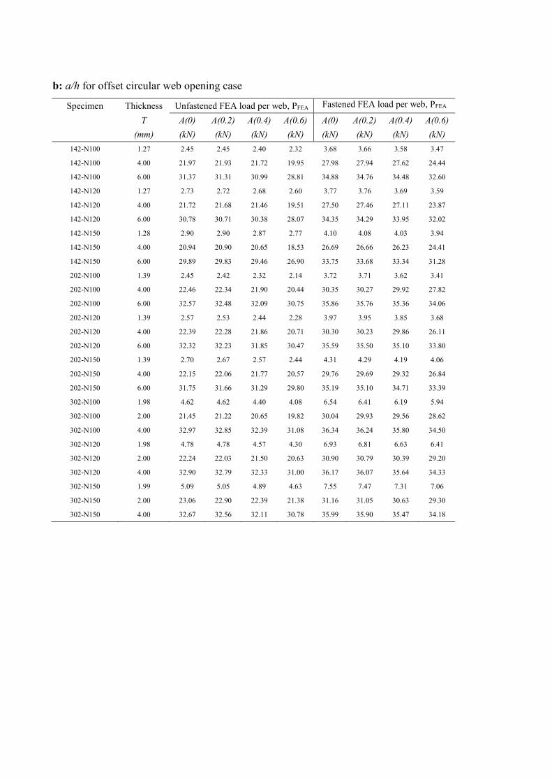
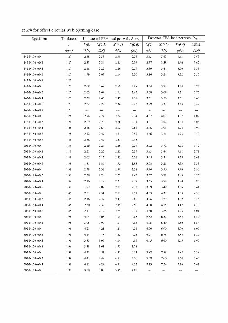
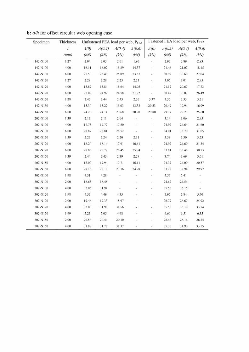
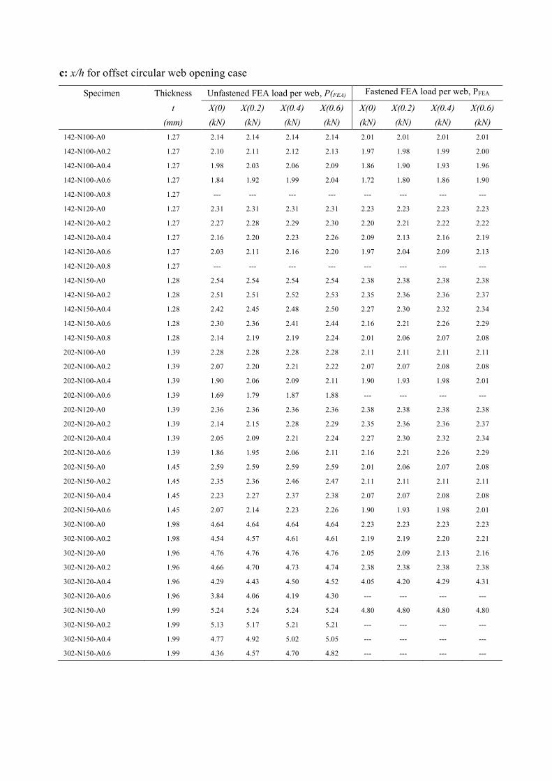
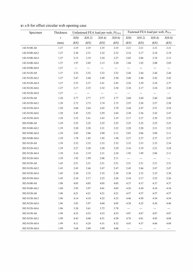
A total of 1,992 specimens was analysed in the parametric study investigating the
effect of the ratios of a/h, N/h and x/h. The web crippling strengths (PFEA) per web predicted
from the FEA are summarised in Tables 3 to 5 for the duplex grade EN 1.4462, austenitic
grade 1.4404 and ferritic grade 1.4003. As can be seen from Tables 3 to 5, the failure load of
the cold-formed stainless steel sections reduces as web openings are present and continues to
reduce with increase in the size of web openings. The results demonstrate that the failure
load obtained from the cold-formed stainless steel sections with the case of flanges fastened
to bearing plate is in average 30% higher than the case of flanges unfastened to bearing
plates for the sections with and without web openings. In addition, for the case of web
openings with a horizontal clear distance to the near edge of the bearing plate, the web
crippling strength of the sections is higher than the case of web openings located centred
above the bearing plates. Moreover, for the same section with different span and bearing
plate, the failure loads were found to be different among the results. Based on the results, it
was found that the failure load increases as the length of the bearing plates increases and as
the length of the sections increases. The effect of the ratios of a/h and x/h on the reduction
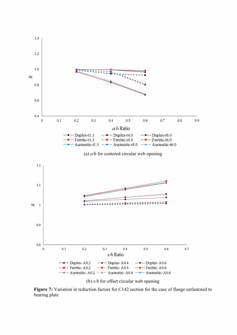
factor of the web crippling strength is shown in Figure 7 for the C142 specimen.
Figure 7(a) shows the ratio of the circular web opening depth to the flat portion of the
web (a/h) versus the strength reduction factor, for the three stainless steel grades. As can be
seen, the reduction in strength increases as the parameter a/h increases for all three stainless
steels, in particular for the ferritic grade with lower thickness (1.3mm). The reduction in
strength of the ferritic grade 6 mm thick section is smallest and the reduction in strength
increases as the section becomes thinner. It can be seen that when the a/h ratio increases
from 0.2 to 0.6, the reduction in strength for the ferritic grade increases by 29%. It also can
be seen that for sections of 4 mm thickness, due to different mechanical properties and more
rounded stress-strain curves of austenitic and ferritic stainless steel grades, compared to the
duplex grade, that there was a small reduction in strength for those two grades. From Figure
7(b) it can be seen that the reduction in strength is sensitive to the horizontal distance of the
web openings to the bearing plate. As the ratio of x/h decreases from 0.6 to 0.2, the strength
reduction factor decreases by 7%. Also, it can again be seen that the reduction in strength is
less for the austenitic grade compared to that of the other two stainless steel grades.
4 Reduction factor comparison with Lian et al. (2016c,d)
For ease of reference, the reduction factor equations proposed by Lian et al. (2016c,d)
are summarised below:
For centered web opening:
Free case 0.96 0.34( ) 0.09( )P
a NR
h h= − + (1)
Fixed case 0.93 0.41( ) 0.16( )P
a NR
h h= − + (2)
For offset web opening:
Free case 0.97 0.26( ) 0.14( )P
a xR
h h= − + (3)
Fixed case: 0.97 0.14( ) 0.07( )P
a xR
h h= − + (4)
where the limits for the reduction factor in Eqns. 1 to 4 are 8.157/ ≤th , 97.120/ ≤tN ,
,15.1/ ≤hN / 0.8a h ≤ , and 090θ = .
In order to evaluate the applicability of the proposed equations to cold-formed
stainless steel grades, an extensive statistical analysis has been performed on all four
proposed equations. Table 6 compares the reduction factors determined from the finite
element models to Eqns. 1 to 4 for cases of centred and offset web opening where the flange
is unfastened to the bearing plate.
As can be seen from Table 6, the four equations proposed by Lian et al. (2016c,d) for
carbon steel are unconservative for the three stainless steel grades, especially for sections
with centred web openings. Examining the strength reduction factor ratios obtained from the
finite element analyses, with the exception of the offset web opening fixed case which has a
mean reduction factor ratio of 1.00 and coefficient of variation (COV) of 0.01, the other
reduction factors from Lian et al. (2016c,d) are unconservative for the stainless steel grades,
especially for the ferritic and austenitic stainless steel grades. For example, for the centred
web opening case for ferritic grade, the mean value of the web crippling reduction factor
ratio is 0.93 and 0.98 for the cases of flange unfastened and fastened to the bearing plate,
respectively; the corresponding values of COV are 0.10 and 0.06, respectively. In the next
section, new equations are proposed for each of the three stainless steel grades.
5 Proposed strength reduction factors
Tables 3 to 5 show the dimensions considered and web crippling strengths of the
duplex, austenitic and ferritic stainless steel sections predicted from the finite element
analysis. Using bivariate linear regression analysis, two unified strength reduction factor
equations (Rp) for three stainless steel grades with web openings are proposed. The
equations are as follows:
Centred web opening ( ) ( ) 1 (5)p
a NR
h hα γ λ= − − ≤
Offset web opening ( ) ( ) 1 (6)p
a xR
h hρ µ ζ= + + ≤
The limits for the reduction factor Eqns. 5 and 6 remain 8.157/ ≤th , 97.120/ ≤tN ,
,15.1/ ≤hN / 0.8a h ≤ , and � = 90°. The coefficients α, γ, λ, ρ, µ and ζ of the equations are
calibrated with the stainless steel analysis results, and the coefficients are presented in Table
7.
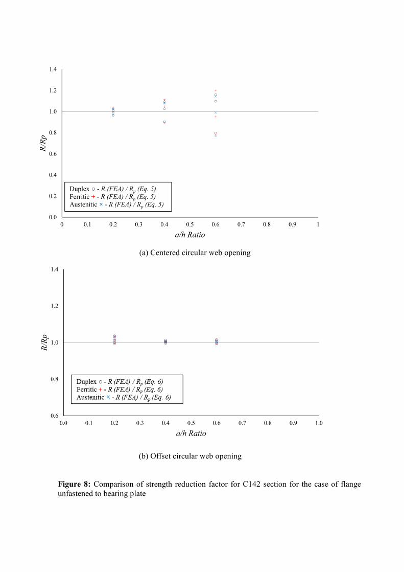
6 Comparison of numerical results with proposed reduction factors
For the three stainless steels grades, the values of the strength reduction factor (R)
obtained from the numerical results are compared with the values of the proposed strength
reduction factor (Rp) calculated using Eqns. 5 and 6. The results for C142 are shown in
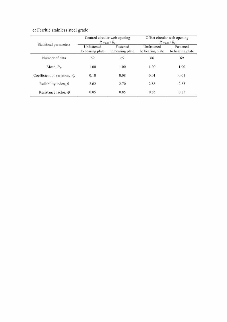
Figure 8. In order to evaluate the accuracy of proposed equations, extensive statistical
reliability analyses are performed. The results are summarized in Table 8. It should be noted,
in calculating the reliability index, the resistance factor of φ=0.85 was used, corresponding
to the reliability index β from the NAS specification. The load combination of 1.2DL +
1.6LL as specified in the NAS specification was used in the reliability analysis, where DL is
the dead load and LL is the live load. In this study, Mm= 1.10 and VM= 0.10, which are the
mean and coefficients of variation for the material properties factors, Fm= 1.00 and VF=
0.05, which are the mean and coefficients of variation for the fabrication factors, and Vq=
0.21, which is the coefficient of variation of load effect were used. According to the NAS
specification, design rules are reliable if the reliability index is more than 2.5. As can be
seen in Table 8, the proposed reduction factors are a good match with the numerical results
for the both cases of flanges unfastened and flanges fastened to the bearing plates and
particularly for the duplex stainless steel grade.
For example, for the centred circular web opening, the mean value of the web
crippling reduction factor ratios are 0.99 and 1.00 for the cases of flange unfastened and
flange fastened to the bearing plate, respectively. The corresponding values of COV are 0.09
and 0.08, respectively. Similarly, the reliability index values (β) are 2.62 and 2.69,
respectively. For the offset circular web opening, the mean value of the web crippling
reduction factor ratios are 1.04 and 1.04 for the cases of flange unfastened and flange
fastened to the bearing plate, respectively. The corresponding values of COV are 0.04 and
0.05, respectively. Similarly, the reliability index values (β) are 2.97 and 2.95, respectively.
Therefore, the proposed strength reduction factor equations are able to reliably predict the
influence of the circular web openings on the web crippling strengths of cold-formed
stainless steel lipped channel-sections under the end-one-flange (EOF) loading condition.
7 Conclusions
In this paper, an investigation into the effect of circular web openings on the web
crippling strength of cold-formed stainless steel lipped channel-sections under the end-one-
flange (EOF) loading condition has been conducted. For this purpose, a parametric study of
1,992 lipped channel-sections of various dimensions and thicknesses were considered for
three stainless steel grades: duplex EN1.4462, austenitic EN1.4404 and ferretic EN1.4003.
Cases with and without circular web openings were considered with web openings located
centred above and offset to the bearing plates.
Strength reduction factor equations have been determined. When the strength
reduction factors were compared against those recently proposed for cold-formed carbon
steel by Lian et al. (2016c,d), it was observed that the cold-formed carbon steel strength
reduction factor equations were unconservative for the stainless steel grades by up to 7%.

Based on finite element results, new unified web crippling strength reduction factor
equations are proposed, considering different web opening diameters and location in the web
for both cases of flanges unfastened and flanges fastened to the bearing plates. Reliability
analysis was performed in order to evaluate the reliability of the proposed strength reduction
factor equations. It was demonstrated that the proposed strength reduction factor equations
are generally conservative and agree well with the analysis results. The proposed new
unified strength reduction factor equations are capable of producing reliable and safe design
values when calibrated according to the NAS specification for resistance factor of 0.85
( 0 .8 5)ϕ = for the end-one-flange (EOF) loading condition.
Acknowledgements
The University of Auckland Doctoral Scholarship is greatly acknowledged and the authors
declare that they have no conflict of interest.
References
ABAQUS. (2014). Analysis User’s Manual-Version 6.14-2 ABAQUS Inc., USA.
Arrayago, I., Real, E. and Gardner, L. (2015). "Description of stress–strain curves for
stainless steel alloys", Materials & Design, Vol. 87, pp. 540-552.
ASCE 8-02 (2002). Specification for the Design of Cold-Formed Stainless Steel Structural
Members: SEI/ASCE 8-02, Reston, VA.
BS 5950-5 (1998), Structural use of steelwork in buildings, Part 5 Code of practice for the
design of cold-formed sections. British Standards Institution, London.
Chen, J., and Young, B. (2006). "Stress–strain curves for stainless steel at elevated
temperatures", Engineering Structures, Vol. 28, No. 2, pp. 229-239.
Eurocode-3 (2006), Design of steel structures: Part 1.3: General rules — Supplementary
rules for cold-formed thin gauge members and sheeting, in: ENV 1993-1-3,
European Committee for Standardization, Brussels, Belgium.
Keerthan, P., and Mahendran, M. (2012). "Shear behaviour and strength of LiteSteel beams
with web openings", Advances in Structural Engineering, Vol. 15, No. 2, pp. 171-
184.

Keerthan, P., Mahendran, M. and Steau, E. (2014). "Experimental study of web crippling
behaviour of hollow flange channel beams under two flange load cases", Thin-
Walled Structures, Vol. 85, pp. 207-219.
Kiymaz, G. and Seckin, E. (2014). "Behavior and design of stainless steel tubular member
welded end connections", Steel and Composite Structures, Vol 17, No. 3, pp. 253-
269.
Korvink, S.A., van den Berg, G.J. and van der Merwe, P. (1995). "Web crippling of stainless
steel cold-formed beams", Journal of Constructional Steel Research, Vol. 34, No. 2-
3, pp. 225-248.
Lawson, R. M., Basta, A. and Uzzaman, A. (2015). "Design of stainless steel sections with
circular openings in shear", Journal of Constructional Steel Research, Vol 112, pp.
228-241.
Lian, Y., Uzzaman A., Lim, J.B.P., Abdelal, G., Nash, D. and Young, B. (2016a). "Effect of
web holes on web crippling strength of cold-formed steel channel sections under
Interior-One-Flange loading condition-Part I: tests and finite element analysis",
Proceeding of The 8th International Conference on Steel and Aluminium Structures,
Hong Kong.
Lian, Y., Uzzaman, A., Lim, J.B.P., Abdelal, G., Nash, D. and Young, B. (2016b).
"Parametric studies and design recommendations of Cold-Formed steel sections with
web openings subjected to web crippling", Proceeding of The 8th International
Conference on Steel and Aluminium Structures, Hong Kong.
Lian, Y., Uzzaman A., Lim, J.B.P., Abdelal, G., Nash, D. and Young, B. (2016c). " Effect of
Web Holes on Web Crippling Strength of Cold-Formed Steel Channel Sections
under End-One-Flange Loading Condition-Part I: Tests and Finite Element
Analysis", Thin-Walled Structures.
Lian, Y., Uzzaman, A., Lim, J.B.P., Abdelal, G., Nash, D. and Young, B. (2016d). "Effect of
Web Holes on Web Crippling Strength of Cold-Formed Steel Channel Sections
under End-One-Flange Loading Condition -Part II: Parametric Study and Proposed
Design Equations, Thin-Walled Structures.
Lim, J.B.P. and Nethercot, D.A. (2004a). "Finite element idealisation of a cold-formed steel
portal frame", Journal of Structural Engineering, 130:1, pp.78-94.
Lim, J.B.P. and Nethercot, D.A. (2004b). "Stiffness prediction for bolted moment-
connections between cold-formed steel members", Journal of Constructional Steel
Research, 60:1, pp.85-107.
NAS (2007). North American Specification for the Design of Cold-Formed Steel Structural
Members: American Iron and Steel Institute, AISI S100-2007, AISI Standard.
Nethercot, D. A., Salih, E. L. and Gardner, L. (2011). "Behaviour and design of stainless
steel bolted connections", Advances in Structural Engineering, Vol. 14, No. 4, pp.
647-658.
Theofanous, M., and Gardner L. (2012). "Effect of element interaction and material
nonlinearity on the ultimate capacity of stainless steel cross-sections", Steel and
Composite Structures, Vol. 12, No. 1, pp. 73-92.
Uzzaman, A., Lim, J. B.P., Nash, D, Rhodes J., and Young, B. (2012a). "Web crippling
behaviour of cold-formed steel channel sections with offset web holes subjected to
end-two-flange loading", Thin-Walled Structures, Vol. 50, pp. 76-86.
Uzzaman, A., Lim, J. B.P., Nash, D, Rhodes J., and Young, B. (2012b). "Cold-formed steel
sections with web openings subjected to web crippling under two-flange loading
conditions-part I: Tests and finite element analysis", Thin-Walled Structures, Vol.
56, pp. 38-48.
Uzzaman, A., Lim, J. B.P., Nash, D, Rhodes J., and Young, B. (2012c). "Cold-formed steel
sections with web openings subjected to web crippling under two-flange loading
conditions-part II: Parametric study and proposed design equations", Thin-Walled
Structures, Vol. 56, pp. 79-87.
Uzzaman, A., Lim, J. B.P., Nash, D, Rhodes J., and Young, B. (2013). "Effect of offset web
holes on web crippling strength of cold-formed steel channel sections under end-two-
flange loading condition", Thin-Walled Structures, Vol. 65, pp. 34-48.
Yousefi, A. M., Lim, J.B.P., Uzzaman, A., Lian, Y., Clifton, G.C. and Young, B. (2016).
"Web crippling strength of cold-formed stainless steel lipped channel-sections with
web openings subjected to Interior-One-Flange loading condition", Steel and
Composite Structures, Vol. 21, No. 3, pp. 629-659.
Zhou, F. and Young, B. (2006). "Yield line mechanism analysis on web crippling of cold-
formed stainless steel tubular sections under two-flange loading", Engineering
Structures, Vol. 28, No. 6, pp. 880-892.
Zhou, F. and Young, B. (2007). "Cold-formed high-strength stainless steel tubular sections
subjected to web crippling", Journal of structural engineering, Vol. 133, No. 3, pp.
368-377.
Zhou, F. and Young, B. (2008). "Web crippling of cold-formed stainless steel tubular
sections", Advances in Structural Engineering, Vol. 11, No. 6, pp. 679-691.
Zhou, F. and Young, B. (2013). "Web crippling behaviour of cold-formed duplex stainless
steel tubular sections at elevated temperatures", Engineering Structures, Vol. 57,
pp.51-62.
List of tables
Table 1: Dimensions and web crippling strengths predicted from finite element analysis of
cold-formed stainless steel lipped channel sections
a: For the case of flange unfastened to the bearing plate
b: For the case of flange fastened to the bearing plate
Table 2: Comparison of numerical results with design strength for the case of flange
fastened to the bearing plate without circular web opening
Table 3: Web crippling strengths of duplex stainless steel sections predicted from finite
element analysis
a: a/h for centred circular web opening case

b: a/h for offset circular web opening case
c: x/h for offset circular web opening case
Table 4: Web crippling strengths of austenitic stainless steel sections predicted from finite
element analysis
a: a/h for centred circular web opening case
b: a/h for offset circular web opening case
c: x/h for offset circular web opening case
Table 5: Web crippling strengths of ferritic stainless steel sections predicted from finite
element analysis
a: a/h for centred circular web opening case
b: a/h for offset circular web opening case
c: x/h for offset circular web opening case
Table 6: Comparison of web crippling strength reduction factor for cold-formed stainless
steel lipped channel sections with reduction factor equations proposed by Lian et al.
(2016c,d)
a: Flange unfastened to the bearing plate
b: Flange fastened to the bearing plate
Table 7: Coefficients of the proposed strength reduction factor equations
Table 8: Statistical analysis of strength reduction factor
a: Duplex stainless steel grade
b: Austenitic stainless steel grade
c: Ferritic stainless steel grade

Table 1: Dimensions and web crippling strengths predicted from finite element analysis of cold-formed stainless steel lipped channel-sections
a: For the case of flange unfastened to the bearing plate
Specimen Web Flange Lip Thickness Length Web
opening
Duplex Ferritic Austenitic
d
(mm)
bf
(mm)
bl
(mm)
t
(mm)
L
(mm)
a
(mm)
P(A0)
(kN)
P(Opening)
(kN)
P(Opening)
(kN)
P(A0)
(kN)
P(Opening )
(kN)
P(Opening )
(kN)
P(A0)
(kN)
P(Opening )
(kN)
P(Opening )
(kN)
Offset Centred Offset Centred Offset Centred
142-N100-MA0.6-FR 141.82 60.63 13.66 1.27 720.0 139.27 2.45 2.31 1.66 2.22 2.12 1.5 2.03 1.96 1.38
142-N120-MA0.6-FR 142.24 60.37 13.90 1.27 740.0 139.70 2.71 2.59 1.91 2.46 2.38 1.72 2.28 2.20 1.61
142-N150-MA0.4-FR 142.40 59.79 13.28 1.28 770.0 139.84 2.89 2.87 2.47 2.63 2.62 2.26 2.44 2.42 2.13
202-N100-MA0.4-FR 202.04 64.79 14.78 1.38 899.2 199.28 2.44 2.31 2.05 2.29 2.15 1.90 2.13 2.03 1.76
202-N100-MA0.6-FR 202.04 64.79 14.78 1.38 899.2 199.28 2.44 2.13 - 2.29 2.02 - 2.13 1.95 -
202-N120-MA0.4-FR 202.00 65.00 14.73 1.38 920.0 199.24 2.56 2.44 2.19 2.42 2.29 2.03 2.20 2.19 1.91
202-N120-MA0.6-FR 202.00 65.00 14.73 1.38 920.0 199.24 2.56 2.27 1.72 2.42 2.16 1.60 2.20 2.10 1.49
202-N150-MA0.4-FR 202.01 65.04 14.98 1.38 950.0 199.24 2.7 2.57 2.34 2.57 2.45 2.18 4.84 2.39 3.88
302-N100-MA0.6-FR 303.18 87.91 18.83 1.90 1200.0 299.37 4.62 4.08 - 4.39 3.95 - 4.30 3.89 -
302-N120-MA0.6-FR 303.07 87.95 18.26 1.90 1221.0 299.26 4.75 4.29 - 4.60 4.16 - 4.52 4.11 -
302-N150-MA0.6-FR 303.03 88.54 18.97 1.90 1249.0 299.23 5.01 4.62 - 4.93 4.49 - 4.84 4.45 -

b: For the case of flange fastened to the bearing plate
Specimen Web Flange Lip Thickness Length Web
opening
Duplex Ferritic Austenitic
d
(mm)
bf
(mm)
bl
(mm)
t
(mm)
L
(mm)
a
(mm)
P(A0)
(kN)
P(Opening)
(kN)
P(Opening )
(kN)
P(A0)
(kN)
P(Opening )
(kN)
P(Opening )
(kN)
P(A0)
(kN)
P(Opening )
(kN)
P(Opening )
(kN)
Offset Centred Offset Centred Offset Centred
142-N100-MA0.6-FX 142.49 60.33 13.79 1.29 720.0 139.27 3.68 3.47 2.67 3.11 2.98 2.28 2.94 1.96 2.12
142-N120-MA0.6-FX 142.38 60.21 13.68 1.29 740.0 139.70 3.77 3.58 2.82 3.22 3.11 2.42 3.05 2.20 2.28
142-N150-MA0.4-FX 142.18 60.12 13.19 1.28 770.0 139.84 4.09 4.02 3.57 3.55 3.50 3.16 3.37 2.42 3.00
202-N100-MA0.4-FX 201.99 64.87 14.76 1.37 900.0 199.28 3.72 3.62 3.06 3.26 3.17 2.73 3.165 2.03 2.62
202-N100-MA0.6-FX 201.99 64.87 14.76 1.37 900.0 199.28 3.72 3.40 - 3.26 3.03 - 3.16 1.95 -
202-N120-MA0.4-FX 202.05 64.99 14.82 1.41 920.0 199.24 3.96 3.84 3.30 3.52 3.41 2.96 3.40 2.19 2.85
202-N120-MA0.6-FX 202.05 64.99 14.82 1.41 920.0 199.24 3.96 3.67 2.78 3.52 3.30 2.45 3.40 2.10 2.28
202-N150-MA0.4-FX 202.00 64.93 15.00 1.41 950.0 199.24 4.31 4.18 3.67 3.89 3.79 3.32 3.76 2.39 3.24
302-N100-MA0.6-FX 303.20 88.24 18.66 1.96 1199.0 299.37 6.53 5.93 - 5.80 5.36 - 5.62 3.89 -
302-N120-MA0.6-FX 303.50 88.53 18.36 1.93 1219.0 299.26 6.93 6.40 - 6.21 5.89 - 6.02 4.11 -
302-N150-MA0.6-FX 303.85 88.71 18.41 1.90 1248.3 299.23 7.55 7.05 - 6.85 6.48 - 6.63 4.45 -
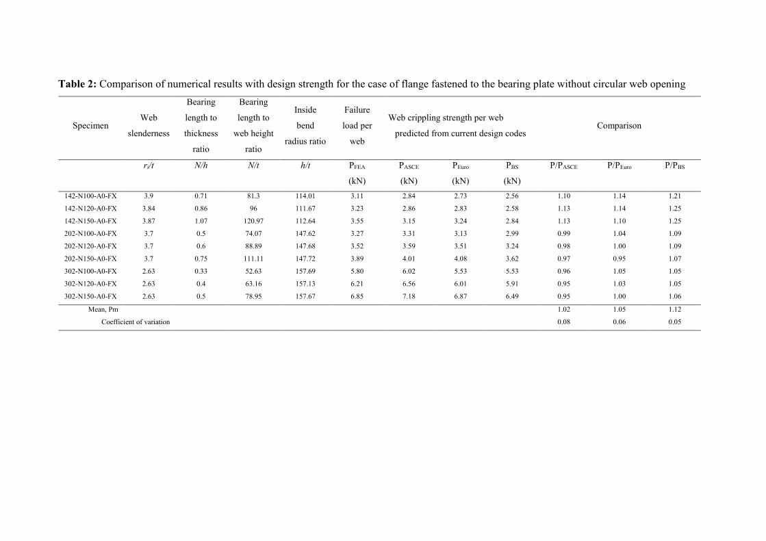
Table 2: Comparison of numerical results with design strength for the case of flange fastened to the bearing plate without circular web opening
Comparison Web crippling strength per web
predicted from current design codes
Failure
load per
web
Inside
bend
radius ratio
Bearing
length to
web height
ratio
Bearing
length to
thickness
ratio
Web
slenderness Specimen
P/PBS P/PEuro P/PASCE PBS
(kN)
PEuro
(kN)
PASCE
(kN)
PFEA
(kN)
h/t N/t N/h ri/t
1.21 1.14 1.10 2.56 2.73 2.84 3.11 114.01 81.3 0.71 3.9 142-N100-A0-FX
1.25 1.14 1.13 2.58 2.83 2.86 3.23 111.67 96 0.86 3.84 142-N120-A0-FX
1.25 1.10 1.13 2.84 3.24 3.15 3.55 112.64 120.97 1.07 3.87 142-N150-A0-FX
1.09 1.04 0.99 2.99 3.13 3.31 3.27 147.62 74.07 0.5 3.7 202-N100-A0-FX
1.09 1.00 0.98 3.24 3.51 3.59 3.52 147.68 88.89 0.6 3.7 202-N120-A0-FX
1.07 0.95 0.97 3.62 4.08 4.01 3.89 147.72 111.11 0.75 3.7 202-N150-A0-FX
1.05 1.05 0.96 5.53 5.53 6.02 5.80 157.69 52.63 0.33 2.63 302-N100-A0-FX
1.05 1.03 0.95 5.91 6.01 6.56 6.21 157.13 63.16 0.4 2.63 302-N120-A0-FX
1.06 1.00 0.95 6.49 6.87 7.18 6.85 157.67 78.95 0.5 2.63 302-N150-A0-FX
1.12 1.05 1.02 Mean, Pm
0.05 0.06 0.08 Coefficient of variation

Table 3: Web crippling strengths of duplex stainless steel sections predicted from finite element
analysis
a: a/h for centred circular web opening case
Specimen Thickness Unfastened FEA load per web, PFEA
Fastened FEA load per web, PFEA
t A(0) A(0.2) A(0.4) A(0.6) A(0.8) A(0) A(0.2) A(0.4) A(0.6) A(0.8)
(mm) (kN) (kN) (kN) (kN) (kN) (kN) (kN) (kN) (kN) (kN)
142-N100 1.27 2.45 2.37 2.05 1.66 - 3.68 3.55 3.07 2.67 -
142-N100 4.00 21.99 21.79 20.74 20.32 - 27.98 27.94 27.74 25.84 -
142-N100 6.00 31.36 31.33 31.16 30.27 - 34.88 34.84 34.66 33.75 -
142-N120 1.27 2.71 2.64 2.29 1.91 - 3.77 3.63 3.23 2.82 -
142-N120 4.00 20.98 20.92 20.89 20.06 - 27.50 27.47 27.33 26.70 -
142-N120 6.00 30.87 30.74 30.59 30.09 - 34.35 34.32 34.16 33.58 -
142-N150 1.28 2.89 2.80 2.47 2.12 1.76 4.10 3.96 3.58 3.18 2.74
142-N150 4.00 20.93 20.85 20.50 19.96 17.25 26.69 26.67 26.57 26.13 22.95
142-N150 6.00 29.89 29.86 29.73 29.35 27.24 33.75 33.72 33.57 33.20 29.84
202-N100 1.39 2.45 2.38 2.05 - - 3.72 3.57 3.06 - -
202-N100 4.00 22.46 21.89 18.06 - - 30.35 30.12 26.59 - -
202-N100 6.00 32.57 32.51 31.97 - - 35.86 35.79 35.46 - -
202-N120 1.39 2.57 2.49 2.20 1.73 - 3.97 3.80 3.31 2.78 -
202-N120 4.00 22.39 22.36 19.47 14.64 - 30.30 30.18 29.30 22.41 -
202-N120 6.00 32.32 32.27 32.00 29.37 - 35.59 35.53 35.28 33.46 -
202-N150 1.39 2.70 2.62 2.34 1.92 - 4.31 4.13 3.68 3.08 -
202-N150 4.00 22.15 21.73 21.01 16.68 - 29.76 29.68 29.32 27.55 -
202-N150 6.00 31.75 31.70 31.50 30.65 - 35.19 35.14 34.92 34.17 -
302-N100 1.98 4.62 4.47 - - - 6.54 6.29 - - -
302-N100 4.00 21.45 20.16 - - - 30.04 28.95 - - -
302-N100 6.00 32.97 32.78 - - - 36.34 36.23 - - -
302-N120 1.98 4.78 4.61 3.82 - - 6.93 6.63 5.36 - -
302-N120 4.00 22.24 20.91 16.82 - - 30.90 30.13 24.93 - -
302-N120 6.00 32.90 32.78 31.39 - - 36.17 36.09 35.36 - -
302-N150 1.99 5.02 4.89 4.00 - - 7.55 7.20 5.94 - -
302-N150 4.00 23.06 21.87 17.95 - - 31.16 30.78 27.71 - -
302-N150 6.00 32.67 32.58 31.94 - - 35.99 35.92 35.57 - -
b: a/h for offset circular web opening case
Specimen Thickness Unfastened FEA load per web, PFEA Fastened FEA load per web, PFEA
T A(0) A(0.2) A(0.4) A(0.6) A(0) A(0.2) A(0.4) A(0.6)
(mm) (kN) (kN) (kN) (kN) (kN) (kN) (kN) (kN)
142-N100 1.27 2.45 2.45 2.40 2.32 3.68 3.66 3.58 3.47
142-N100 4.00 21.97 21.93 21.72 19.95 27.98 27.94 27.62 24.44
142-N100 6.00 31.37 31.31 30.99 28.81 34.88 34.76 34.48 32.60
142-N120 1.27 2.73 2.72 2.68 2.60 3.77 3.76 3.69 3.59
142-N120 4.00 21.72 21.68 21.46 19.51 27.50 27.46 27.11 23.87
142-N120 6.00 30.78 30.71 30.38 28.07 34.35 34.29 33.95 32.02
142-N150 1.28 2.90 2.90 2.87 2.77 4.10 4.08 4.03 3.94
142-N150 4.00 20.94 20.90 20.65 18.53 26.69 26.66 26.23 24.41
142-N150 6.00 29.89 29.83 29.46 26.90 33.75 33.68 33.34 31.28
202-N100 1.39 2.45 2.42 2.32 2.14 3.72 3.71 3.62 3.41
202-N100 4.00 22.46 22.34 21.90 20.44 30.35 30.27 29.92 27.82
202-N100 6.00 32.57 32.48 32.09 30.75 35.86 35.76 35.36 34.06
202-N120 1.39 2.57 2.53 2.44 2.28 3.97 3.95 3.85 3.68
202-N120 4.00 22.39 22.28 21.86 20.71 30.30 30.23 29.86 26.11
202-N120 6.00 32.32 32.23 31.85 30.47 35.59 35.50 35.10 33.80
202-N150 1.39 2.70 2.67 2.57 2.44 4.31 4.29 4.19 4.06
202-N150 4.00 22.15 22.06 21.77 20.57 29.76 29.69 29.32 26.84
202-N150 6.00 31.75 31.66 31.29 29.80 35.19 35.10 34.71 33.39
302-N100 1.98 4.62 4.62 4.40 4.08 6.54 6.41 6.19 5.94
302-N100 2.00 21.45 21.22 20.65 19.82 30.04 29.93 29.56 28.62
302-N100 4.00 32.97 32.85 32.39 31.08 36.34 36.24 35.80 34.50
302-N120 1.98 4.78 4.78 4.57 4.30 6.93 6.81 6.63 6.41
302-N120 2.00 22.24 22.03 21.50 20.63 30.90 30.79 30.39 29.20
302-N120 4.00 32.90 32.79 32.33 31.00 36.17 36.07 35.64 34.33
302-N150 1.99 5.09 5.05 4.89 4.63 7.55 7.47 7.31 7.06
302-N150 2.00 23.06 22.90 22.39 21.38 31.16 31.05 30.63 29.30
302-N150 4.00 32.67 32.56 32.11 30.78 35.99 35.90 35.47 34.18
c: x/h for offset circular web opening case
Specimen Thickness Unfastened FEA load per web, P(FEA) Fastened FEA load per web, PFEA
t X(0) X(0.2) X(0.4) X(0.6) X(0) X(0.2) X(0.4) X(0.6)
(mm) (kN) (kN) (kN) (kN) (kN) (kN) (kN) (kN)
142-N100-A0 1.27 2.38 2.38 2.38 2.38 3.63 3.63 3.63 3.63
142-N100-A0.2 1.27 2.33 2.34 2.35 2.36 3.57 3.58 3.60 3.62
142-N100-A0.4 1.27 2.18 2.22 2.26 2.29 3.39 3.44 3.50 3.53
142-N100-A0.6 1.27 1.99 2.07 2.14 2.20 3.16 3.24 3.32 3.37
142-N100-A0.8 1.27 --- --- --- --- --- --- --- ---
142-N120-A0 1.27 2.68 2.68 2.68 2.68 3.74 3.74 3.74 3.74
142-N120-A0.2 1.27 2.63 2.64 2.65 2.63 3.68 3.69 3.71 3.73
142-N120-A0.4 1.27 2.39 2.43 2.47 2.39 3.51 3.56 3.61 3.63
142-N120-A0.6 1.27 2.22 2.29 2.36 2.22 3.29 3.37 3.43 3.47
142-N120-A0.8 1.27 --- --- --- --- --- --- --- ---
142-N150-A0 1.28 2.74 2.74 2.74 2.74 4.07 4.07 4.07 4.07
142-N150-A0.2 1.28 2.69 2.70 2.70 2.71 4.01 4.02 4.04 4.06
142-N150-A0.4 1.28 2.56 2.60 2.62 2.65 3.86 3.91 3.94 3.96
142-N150-A0.6 1.28 2.42 2.47 2.53 2.57 3.66 3.71 3.75 3.79
142-N150-A0.8 1.28 2.38 2.47 2.53 2.55 --- --- --- ---
202-N100-A0 1.39 2.26 2.26 2.26 2.26 3.72 3.72 3.72 3.72
202-N100-A0.2 1.39 2.21 2.22 2.22 2.37 3.63 3.64 3.68 3.71
202-N100-A0.4 1.39 2.05 2.17 2.23 2.26 3.45 3.54 3.55 3.61
202-N100-A0.6 1.39 1.81 1.86 1.92 1.98 3.08 3.21 3.33 3.38
202-N120-A0 1.39 2.38 2.38 2.38 2.38 3.96 3.96 3.96 3.96
202-N120-A0.2 1.39 2.28 2.28 2.29 2.42 3.67 3.71 3.93 3.96
202-N120-A0.4 1.39 2.16 2.19 2.21 2.37 3.65 3.74 3.80 3.85
202-N120-A0.6 1.39 1.92 2.07 2.07 2.22 3.39 3.49 3.56 3.61
202-N150-A0 1.45 2.51 2.51 2.51 2.51 4.33 4.33 4.33 4.33
202-N150-A0.2 1.45 2.46 2.47 2.47 2.60 4.26 4.29 4.32 4.34
202-N150-A0.4 1.45 2.30 2.32 2.35 2.50 4.08 4.15 4.17 4.19
202-N150-A0.6 1.45 2.11 2.19 2.25 2.37 3.80 3.88 3.93 4.01
302-N100-A0 1.98 4.05 4.05 4.05 4.05 6.52 6.52 6.52 6.52
302-N100-A0.2 1.98 3.95 3.97 4.01 4.05 6.35 6.49 6.50 6.54
302-N120-A0 1.96 4.21 4.21 4.21 4.21 6.90 6.90 6.90 6.90
302-N120-A0.2 1.96 4.14 4.18 4.22 4.23 6.71 6.78 6.85 6.89
302-N120-A0.4 1.96 3.83 3.97 4.04 4.05 6.45 6.60 6.65 6.67
302-N120-A0.6 1.96 3.38 3.61 3.72 3.78 --- --- --- ---
302-N150-A0 1.99 4.53 4.53 4.53 4.53 7.88 7.88 7.88 7.88
302-N150-A0.2 1.99 4.43 4.48 4.51 4.50 7.58 7.60 7.64 7.67
302-N150-A0.4 1.99 4.11 4.24 4.31 4.32 7.19 7.24 7.26 7.41
302-N150-A0.6 1.99 3.68 3.89 3.99 4.06 --- --- --- ---

Table 4: Web crippling strengths of austenitic stainless steel sections predicted from finite element
analysis
a: a/h for centred circular web opening case
Specimen Thickness Unfastened FEA load per web, PFEA
Fastened FEA load per web, PFEA
t A(0) A(0.2) A(0.4) A(0.6) A(0.8) A(0) A(0.2) A(0.4) A(0.6) A(0.8)
(mm) (kN) (kN) (kN) (kN) (kN) (kN) (kN) (kN) (kN) (kN)
142-N100 1.27 1.73 1.39 - 2.94 2.91 2.54 2.13 - 2.04 1.99
142-N100 4.00 15.56 13.07 - 21.50 21.47 21.29 19.28 - 16.11 16.06
142-N100 6.00 25.32 24.91 - 31.03 31.00 30.85 29.87 - 25.50 25.45
142-N120 1.27 1.94 1.61 - 3.05 2.99 2.66 2.28 - 2.28 2.22
142-N120 4.00 15.64 14.42 - 21.15 21.13 21.02 20.58 - 15.87 15.83
142-N120 6.00 24.90 24.69 - 30.53 30.50 30.39 29.69 - 25.02 24.99
142-N150 1.28 2.13 1.82 1.51 3.37 3.28 3.01 2.66 2.26 2.45 2.38
142-N150 4.00 15.18 14.86 13.32 20.53 20.51 20.44 20.17 18.28 15.30 15.27
142-N150 6.00 24.09 23.91 22.66 29.80 29.78 29.68 29.14 26.14 24.20 24.17
202-N100 1.39 1.76 - - 3.17 3.10 2.62 - - 2.13 2.09
202-N100 4.00 14.33 - - 24.96 24.62 20.77 - - 17.78 17.27
202-N100 6.00 28.51 - - 34.08 34.03 33.72 - - 28.87 28.85
202-N120 1.39 1.91 1.50 - 3.41 3.31 2.86 2.29 - 2.26 2.21
202-N120 4.00 15.41 11.41 - 24.96 24.85 22.94 17.46 - 18.20 17.85
202-N120 6.00 28.79 24.53 - 33.87 33.83 33.62 30.09 - 28.83 28.84
202-N150 1.39 2.09 1.68 - 3.76 3.65 3.24 2.64 - 2.44 2.37
202-N150 4.00 16.59 13.32 - 24.41 24.35 24.09 21.35 - 18.00 17.84
202-N150 6.00 28.14 28.04 - 33.34 33.30 33.13 32.14 - 28.16 28.16
302-N100 1.98 - - - 5.62 5.53 - - - 4.31 4.20
302-N100 4.00 - - - 24.72 24.49 - - - 18.63 17.79
302-N100 6.00 - - - 35.65 35.55 - - - 32.05 31.81
302-N120 1.98 3.57 - - 6.02 5.88 4.66 - - 4.53 4.39
302-N120 4.00 14.46 - - 26.79 26.14 20.54 - - 19.46 18.51
302-N120 6.00 29.86 - - 35.60 35.51 34.64 - - 32.08 31.96
302-N150 1.99 3.89 - - 6.64 6.45 5.31 - - 4.85 4.69
302-N150 4.00 15.58 - - 28.54 27.98 23.09 - - 20.56 19.48
302-N150 6.00 30.75 - - 35.99 35.92 35.57 - - 31.88 31.81
b: a/h for offset circular web opening case
Specimen Thickness Unfastened FEA load per web, PFEA Fastened FEA load per web, PFEA
t A(0) A(0.2) A(0.4) A(0.6) A(0) A(0.2) A(0.4) A(0.6)
(mm) (kN) (kN) (kN) (kN) (kN) (kN) (kN) (kN)
142-N100 1.27 2.04 2.03 2.01 1.96 - 2.93 2.89 2.83
142-N100 4.00 16.11 16.07 15.89 14.37 - 21.46 21.07 18.15
142-N100 6.00 25.50 25.43 25.09 23.87 - 30.99 30.60 27.04
142-N120 1.27 2.28 2.28 2.25 2.21 - 3.05 3.01 2.95
142-N120 4.00 15.87 15.84 15.64 14.05 - 21.12 20.67 17.73
142-N120 6.00 25.02 24.97 24.58 21.72 - 30.49 30.07 26.49
142-N150 1.28 2.45 2.44 2.43 2.36 3.37 3.37 3.33 3.21
142-N150 4.00 15.30 15.27 15.03 13.33 20.53 20.49 19.94 16.99
142-N150 6.00 24.20 24.14 23.68 20.70 29.80 29.77 29.23 25.60
202-N100 1.39 2.13 2.11 2.04 - - 3.14 3.06 2.95
202-N100 4.00 17.78 17.72 17.50 - - 24.92 24.64 21.60
202-N100 6.00 28.87 28.81 28.52 - - 34.01 33.70 31.05
202-N120 1.39 2.26 2.24 2.20 2.11 - 3.38 3.30 3.23
202-N120 4.00 18.20 18.14 17.91 16.61 - 24.92 24.60 21.34
202-N120 6.00 28.83 28.77 28.45 25.94 - 33.81 33.48 30.73
202-N150 1.39 2.44 2.43 2.39 2.29 - 3.74 3.69 3.61
202-N150 4.00 18.00 17.94 17.71 16.11 - 24.37 24.00 20.57
202-N150 6.00 28.16 28.10 27.76 24.98 - 33.28 32.94 29.97
302-N100 1.98 4.31 4.28 - - - 5.56 5.41 -
302-N100 2.00 18.63 18.48 - - - 24.67 24.54 -
302-N100 4.00 32.05 31.94 - - - 35.56 35.15 -
302-N120 1.98 4.53 4.49 4.35 - - 5.97 5.84 5.70
302-N120 2.00 19.46 19.33 18.97 - - 26.79 26.67 25.92
302-N120 4.00 32.08 31.98 31.56 - - 35.50 35.10 33.74
302-N150 1.99 5.23 5.05 4.68 - - 6.60 6.51 6.35
302-N150 2.00 20.56 20.44 20.10 - - 28.46 28.16 26.24
302-N150 4.00 31.88 31.78 31.37 - - 35.30 34.90 33.55
c: x/h for offset circular web opening case
Specimen Thickness Unfastened FEA load per web, P(FEA) Fastened FEA load per web, PFEA
t X(0) X(0.2) X(0.4) X(0.6) X(0) X(0.2) X(0.4) X(0.6)
(mm) (kN) (kN) (kN) (kN) (kN) (kN) (kN) (kN)
142-N100-A0 1.27 2.14 2.14 2.14 2.14 2.01 2.01 2.01 2.01
142-N100-A0.2 1.27 2.10 2.11 2.12 2.13 1.97 1.98 1.99 2.00
142-N100-A0.4 1.27 1.98 2.03 2.06 2.09 1.86 1.90 1.93 1.96
142-N100-A0.6 1.27 1.84 1.92 1.99 2.04 1.72 1.80 1.86 1.90
142-N100-A0.8 1.27 --- --- --- --- --- --- --- ---
142-N120-A0 1.27 2.31 2.31 2.31 2.31 2.23 2.23 2.23 2.23
142-N120-A0.2 1.27 2.27 2.28 2.29 2.30 2.20 2.21 2.22 2.22
142-N120-A0.4 1.27 2.16 2.20 2.23 2.26 2.09 2.13 2.16 2.19
142-N120-A0.6 1.27 2.03 2.11 2.16 2.20 1.97 2.04 2.09 2.13
142-N120-A0.8 1.27 --- --- --- --- --- --- --- ---
142-N150-A0 1.28 2.54 2.54 2.54 2.54 2.38 2.38 2.38 2.38
142-N150-A0.2 1.28 2.51 2.51 2.52 2.53 2.35 2.36 2.36 2.37
142-N150-A0.4 1.28 2.42 2.45 2.48 2.50 2.27 2.30 2.32 2.34
142-N150-A0.6 1.28 2.30 2.36 2.41 2.44 2.16 2.21 2.26 2.29
142-N150-A0.8 1.28 2.14 2.19 2.19 2.24 2.01 2.06 2.07 2.08
202-N100-A0 1.39 2.28 2.28 2.28 2.28 2.11 2.11 2.11 2.11
202-N100-A0.2 1.39 2.07 2.20 2.21 2.22 2.07 2.07 2.08 2.08
202-N100-A0.4 1.39 1.90 2.06 2.09 2.11 1.90 1.93 1.98 2.01
202-N100-A0.6 1.39 1.69 1.79 1.87 1.88 --- --- --- ---
202-N120-A0 1.39 2.36 2.36 2.36 2.36 2.38 2.38 2.38 2.38
202-N120-A0.2 1.39 2.14 2.15 2.28 2.29 2.35 2.36 2.36 2.37
202-N120-A0.4 1.39 2.05 2.09 2.21 2.24 2.27 2.30 2.32 2.34
202-N120-A0.6 1.39 1.86 1.95 2.06 2.11 2.16 2.21 2.26 2.29
202-N150-A0 1.45 2.59 2.59 2.59 2.59 2.01 2.06 2.07 2.08
202-N150-A0.2 1.45 2.35 2.36 2.46 2.47 2.11 2.11 2.11 2.11
202-N150-A0.4 1.45 2.23 2.27 2.37 2.38 2.07 2.07 2.08 2.08
202-N150-A0.6 1.45 2.07 2.14 2.23 2.26 1.90 1.93 1.98 2.01
302-N100-A0 1.98 4.64 4.64 4.64 4.64 2.23 2.23 2.23 2.23
302-N100-A0.2 1.98 4.54 4.57 4.61 4.61 2.19 2.19 2.20 2.21
302-N120-A0 1.96 4.76 4.76 4.76 4.76 2.05 2.09 2.13 2.16
302-N120-A0.2 1.96 4.66 4.70 4.73 4.74 2.38 2.38 2.38 2.38
302-N120-A0.4 1.96 4.29 4.43 4.50 4.52 4.05 4.20 4.29 4.31
302-N120-A0.6 1.96 3.84 4.06 4.19 4.30 --- --- --- ---
302-N150-A0 1.99 5.24 5.24 5.24 5.24 4.80 4.80 4.80 4.80
302-N150-A0.2 1.99 5.13 5.17 5.21 5.21 --- --- --- ---
302-N150-A0.4 1.99 4.77 4.92 5.02 5.05 --- --- --- ---
302-N150-A0.6 1.99 4.36 4.57 4.70 4.82 --- --- --- ---
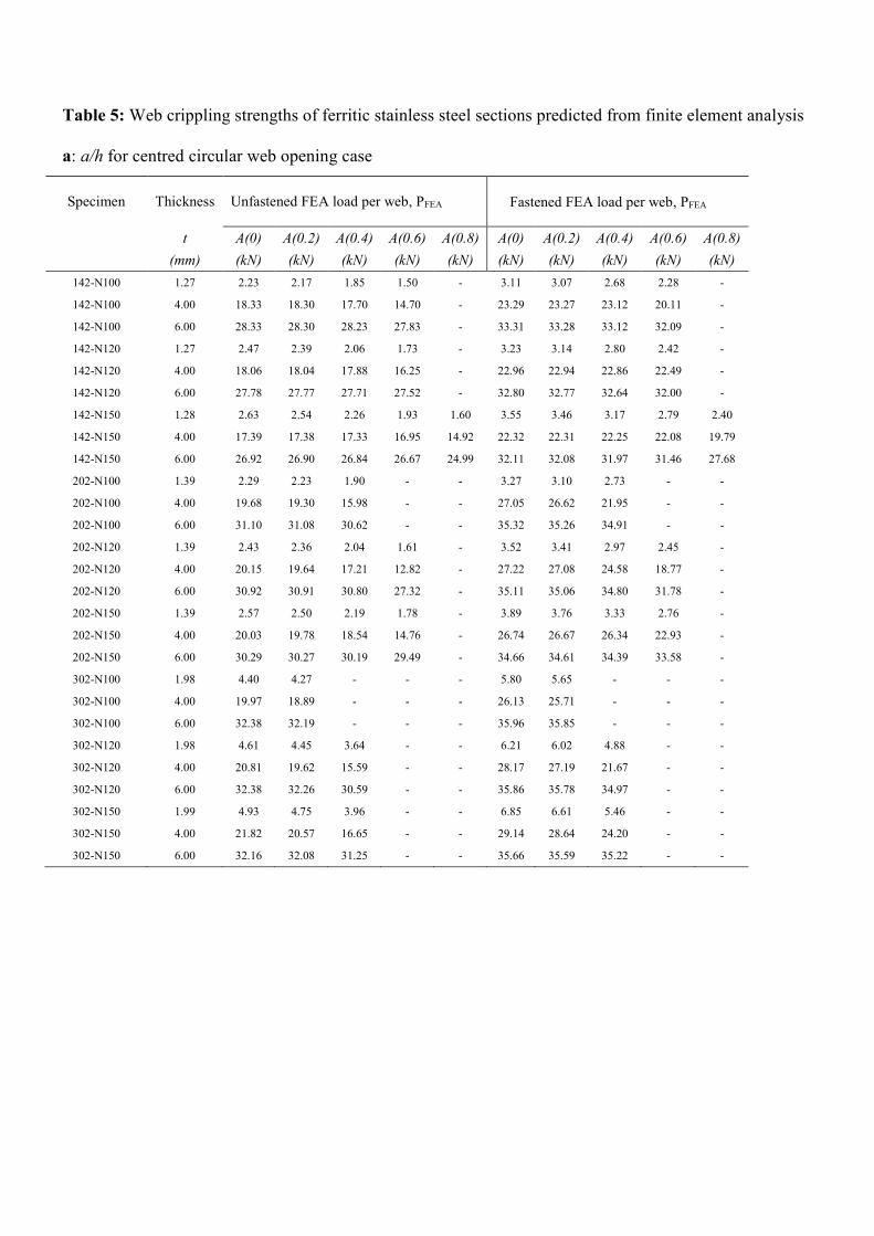
Table 5: Web crippling strengths of ferritic stainless steel sections predicted from finite element analysis
a: a/h for centred circular web opening case
Specimen Thickness Unfastened FEA load per web, PFEA
Fastened FEA load per web, PFEA
t A(0) A(0.2) A(0.4) A(0.6) A(0.8) A(0) A(0.2) A(0.4) A(0.6) A(0.8)
(mm) (kN) (kN) (kN) (kN) (kN) (kN) (kN) (kN) (kN) (kN)
142-N100 1.27 2.23 2.17 1.85 1.50 - 3.11 3.07 2.68 2.28 -
142-N100 4.00 18.33 18.30 17.70 14.70 - 23.29 23.27 23.12 20.11 -
142-N100 6.00 28.33 28.30 28.23 27.83 - 33.31 33.28 33.12 32.09 -
142-N120 1.27 2.47 2.39 2.06 1.73 - 3.23 3.14 2.80 2.42 -
142-N120 4.00 18.06 18.04 17.88 16.25 - 22.96 22.94 22.86 22.49 -
142-N120 6.00 27.78 27.77 27.71 27.52 - 32.80 32.77 32.64 32.00 -
142-N150 1.28 2.63 2.54 2.26 1.93 1.60 3.55 3.46 3.17 2.79 2.40
142-N150 4.00 17.39 17.38 17.33 16.95 14.92 22.32 22.31 22.25 22.08 19.79
142-N150 6.00 26.92 26.90 26.84 26.67 24.99 32.11 32.08 31.97 31.46 27.68
202-N100 1.39 2.29 2.23 1.90 - - 3.27 3.10 2.73 - -
202-N100 4.00 19.68 19.30 15.98 - - 27.05 26.62 21.95 - -
202-N100 6.00 31.10 31.08 30.62 - - 35.32 35.26 34.91 - -
202-N120 1.39 2.43 2.36 2.04 1.61 - 3.52 3.41 2.97 2.45 -
202-N120 4.00 20.15 19.64 17.21 12.82 - 27.22 27.08 24.58 18.77 -
202-N120 6.00 30.92 30.91 30.80 27.32 - 35.11 35.06 34.80 31.78 -
202-N150 1.39 2.57 2.50 2.19 1.78 - 3.89 3.76 3.33 2.76 -
202-N150 4.00 20.03 19.78 18.54 14.76 - 26.74 26.67 26.34 22.93 -
202-N150 6.00 30.29 30.27 30.19 29.49 - 34.66 34.61 34.39 33.58 -
302-N100 1.98 4.40 4.27 - - - 5.80 5.65 - - -
302-N100 4.00 19.97 18.89 - - - 26.13 25.71 - - -
302-N100 6.00 32.38 32.19 - - - 35.96 35.85 - - -
302-N120 1.98 4.61 4.45 3.64 - - 6.21 6.02 4.88 - -
302-N120 4.00 20.81 19.62 15.59 - - 28.17 27.19 21.67 - -
302-N120 6.00 32.38 32.26 30.59 - - 35.86 35.78 34.97 - -
302-N150 1.99 4.93 4.75 3.96 - - 6.85 6.61 5.46 - -
302-N150 4.00 21.82 20.57 16.65 - - 29.14 28.64 24.20 - -
302-N150 6.00 32.16 32.08 31.25 - - 35.66 35.59 35.22 - -

b: a/h for offset circular web opening case
Specimen Thickness Unfastened FEA load per web, PFEA Fastened FEA load per web, PFEA
t A(0) A(0.2) A(0.4) A(0.6) A(0) A(0.2) A(0.4) A(0.6)
(mm) (kN) (kN) (kN) (kN) (kN) (kN) (kN) (kN)
142-N100 1.27 2.23 2.22 2.18 2.12 3.11 3.10 3.05 2.98
142-N100 4.00 18.33 18.31 18.20 16.73 23.29 23.27 23.16 20.53
142-N100 6.00 28.32 28.28 28.07 25.53 33.31 33.26 32.97 30.04
142-N120 1.27 2.47 2.46 2.44 2.38 3.23 3.22 3.17 3.11
142-N120 4.00 18.06 18.03 17.92 16.28 22.96 22.94 22.82 20.02
142-N120 6.00 27.78 27.75 27.51 24.72 32.80 32.75 32.45 29.43
142-N150 1.28 2.63 2.63 2.62 2.54 3.55 3.55 3.51 3.44
142-N150 4.00 17.39 17.37 17.25 15.42 22.32 22.31 22.15 19.14
142-N150 6.00 26.92 26.88 26.60 23.56 32.11 32.06 31.71 28.53
202-N100 1.39 2.29 2.26 2.15 2.02 3.27 3.25 3.18 3.03
202-N100 4.00 19.68 19.60 19.33 18.44 27.05 27.00 26.79 24.54
202-N100 6.00 31.10 31.03 30.74 29.20 35.32 35.23 34.86 33.21
202-N120 1.39 2.43 2.40 2.29 2.16 3.52 3.49 3.41 3.31
202-N120 4.00 20.15 20.07 19.82 18.82 27.22 27.18 24.60 24.37
202-N120 6.00 30.92 30.85 30.55 28.88 35.11 35.03 33.48 32.96
202-N150 1.39 2.57 2.54 2.45 2.32 3.89 3.87 3.79 3.70
202-N150 4.00 20.03 19.97 19.73 18.47 26.74 26.70 26.47 23.60
202-N150 6.00 30.29 30.22 29.91 28.02 34.66 34.58 34.21 32.39
302-N100 1.98 4.40 4.39 4.21 3.95 5.80 5.72 5.55 5.36
302-N100 2.00 19.97 19.79 19.32 18.62 26.13 26.06 25.88 25.60
302-N100 4.00 32.38 32.27 31.82 30.54 35.96 35.86 35.43 34.14
302-N120 1.98 4.61 4.57 4.42 4.17 6.21 6.15 6.01 5.89
302-N120 2.00 20.81 20.64 20.22 19.51 28.17 28.10 27.84 27.06
302-N120 4.00 32.38 32.27 31.82 30.50 35.86 35.76 35.33 34.02
302-N150 1.99 4.93 4.90 4.75 4.49 6.85 6.81 6.70 6.49
302-N150 2.00 21.82 21.67 21.25 20.41 29.14 29.07 28.74 27.60
302-N150 4.00 32.16 32.06 31.61 30.29 35.66 35.56 35.14 33.84
c: x/h for offset circular web opening case
Specimen Thickness Unfastened FEA load per web, P(FEA) Fastened FEA load per web, PFEA
t X(0) X(0.2) X(0.4) X(0.6) X(0) X(0.2) X(0.4) X(0.6)
(mm) (kN) (kN) (kN) (kN) (kN) (kN) (kN) (kN)
142-N100-A0 1.27 2.35 2.35 2.35 2.35 2.21 2.21 2.21 2.21
142-N100-A0.2 1.27 2.30 2.31 2.32 2.33 2.16 2.17 2.18 2.19
142-N100-A0.4 1.27 2.15 2.19 2.24 2.27 2.02 2.06 2.10 2.13
142-N100-A0.6 1.27 1.97 2.05 2.13 2.20 1.84 1.92 2.00 2.05
142-N100-A0.8 1.27 --- --- --- --- --- --- --- ---
142-N120-A0 1.27 2.52 2.52 2.52 2.52 2.44 2.44 2.44 2.44
142-N120-A0.2 1.27 2.47 2.48 2.49 2.50 2.40 2.40 2.42 2.42
142-N120-A0.4 1.27 2.33 2.37 2.41 2.45 2.26 2.30 2.34 2.37
142-N120-A0.6 1.27 2.17 2.25 2.32 2.38 2.10 2.17 2.24 2.30
142-N120-A0.8 1.27 --- --- --- --- --- --- --- ---
142-N150-A0 1.28 2.77 2.77 2.77 2.77 2.60 2.60 2.60 2.60
142-N150-A0.2 1.28 2.72 2.73 2.74 2.75 2.55 2.56 2.57 2.58
142-N150-A0.4 1.28 2.60 2.64 2.65 2.70 2.44 2.47 2.51 2.54
142-N150-A0.6 1.28 2.45 2.52 2.59 2.64 2.30 2.36 2.42 2.47
142-N150-A0.8 1.28 2.32 2.41 2.43 2.35 2.17 2.27 2.29 2.53
202-N100-A0 1.39 2.25 2.25 2.25 2.25 2.25 2.25 2.25 2.25
202-N100-A0.2 1.39 2.20 2.20 2.21 2.22 2.20 2.20 2.21 2.22
202-N100-A0.4 1.39 2.03 2.06 2.09 2.11 2.03 2.06 2.09 2.11
202-N100-A0.6 1.39 1.78 1.85 1.92 1.98 2.37 2.37 2.37 2.37
202-N120-A0 1.39 2.32 2.32 2.32 2.32 2.32 2.33 2.33 2.34
202-N120-A0.2 1.39 2.27 2.28 2.28 2.29 2.16 2.19 2.21 2.24
202-N120-A0.4 1.39 2.16 2.19 2.21 2.24 1.92 1.99 2.06 2.11
202-N120-A0.6 1.39 1.92 1.99 2.06 2.11 --- --- --- ---
202-N150-A0 1.45 2.51 2.51 2.51 2.51 2.51 2.51 2.51 2.51
202-N150-A0.2 1.45 2.45 2.46 2.47 2.47 2.45 2.46 2.47 2.47
202-N150-A0.4 1.45 2.30 2.33 2.35 2.38 2.30 2.33 2.35 2.38
202-N150-A0.6 1.45 2.10 2.17 2.23 2.26 2.10 2.17 2.23 2.26
302-N100-A0 1.98 4.05 4.05 4.05 4.05 4.37 4.37 4.37 4.37
302-N100-A0.2 1.98 3.95 3.97 4.01 4.05 4.26 4.30 4.34 4.34
302-N120-A0 1.96 4.21 4.21 4.21 4.21 4.57 4.57 4.57 4.57
302-N120-A0.2 1.96 4.14 4.18 4.22 4.23 4.46 4.50 4.54 4.54
302-N120-A0.4 1.96 3.83 3.97 4.04 4.05 4.38 4.25 4.36 4.46
302-N120-A0.6 1.96 3.38 3.61 3.72 3.78 --- --- --- ---
302-N150-A0 1.99 4.53 4.53 4.53 4.53 4.87 4.87 4.87 4.87
302-N150-A0.2 1.99 4.43 4.48 4.51 4.50 4.76 4.81 4.85 4.84
302-N150-A0.4 1.99 4.11 4.24 4.31 4.32 4.43 4.57 4.66 4.68
302-N150-A0.6 1.99 3.68 3.89 3.99 4.06 --- --- --- ---
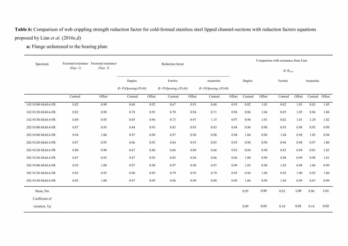
Table 6: Comparison of web crippling strength reduction factor for cold-formed stainless steel lipped channel-sections with reduction factors equations
proposed by Lian et al. (2016c,d)
a: Flange unfastened to the bearing plate
Specimen Factored resistance
(Eqn. 1) Factored resistance
(Eqn. 3)
Reduction factor
Comparison with resistance from Lian
R/ RLian
Duplex
Ferritic
Austenitic
Duplex
Ferritic
Austenitic
R=P(Opening)/P(A0) R=P(Opening )/P(A0) R=P(Opening )/P(A0)
Centred Offset Centred Offset Centred Offset Centred Offset Centred Offset Centred Offset Centred Offset
142-N100-MA0.6-FR 0.82 0.90 0.68 0.92 0.67 0.93 0.68 0.95 0.82 1.03 0.82 1.03 0.83 1.05
142-N120-MA0.6-FR 0.82 0.90 0.70 0.93 0.70 0.94 0.71 0.96 0.86 1.04 0.85 1.05 0.86 1.06
142-N150-MA0.4-FR 0.89 0.95 0.85 0.96 0.73 0.97 1.15 0.97 0.96 1.01 0.82 1.01 1.29 1.02
202-N100-MA0.4-FR 0.87 0.95 0.84 0.93 0.83 0.93 0.83 0.94 0.96 0.98 0.95 0.98 0.95 0.99
202-N100-MA0.6-FR 0.94 1.00 0.97 0.98 0.97 0.98 0.98 0.98 1.04 0.98 1.04 0.98 1.05 0.98
202-N120-MA0.4-FR 0.87 0.95 0.86 0.93 0.84 0.93 0.85 0.95 0.98 0.98 0.96 0.98 0.97 1.00
202-N120-MA0.6-FR 0.80 0.90 0.67 0.88 0.66 0.89 0.66 0.92 0.84 0.98 0.83 0.99 0.83 1.03
202-N150-MA0.4-FR 0.87 0.95 0.87 0.95 0.85 0.94 0.86 0.96 1.00 0.99 0.98 0.99 0.98 1.01
302-N100-MA0.6-FR 0.92 1.00 0.97 0.98 0.97 0.98 0.97 0.99 1.05 0.98 1.05 0.98 1.06 0.99
302-N120-MA0.6-FR 0.85 0.95 0.80 0.95 0.79 0.95 0.79 0.95 0.94 1.00 0.92 1.00 0.92 1.00
302-N150-MA0.6-FR 0.92 1.00 0.97 0.99 0.96 0.99 0.80 0.99 1.06 0.98 1.04 0.99 0.87 0.99
Mean, Pm 0.95 0.99 0.93 1.00 0.96 1.01
Coefficient of
variation, Vp
0.09 0.02 0.10 0.02 0.14 0.03

b: Flange fastened to the bearing plate
Specimen Factored resistance
(Eqn. 2) Factored resistance
(Eqn. 4)
Reduction factor
Comparison with resistance from Lian
R/ RLian
Duplex Ferritic Austenitic Duplex
Ferritic
Austenitic
R=P(Hole)/P(A0) R=P(Hole)/P(A0) R=P(Hole)/P(A0)
Centred Offset Centred Offset Centred Offset Centred Offset Centred Offset Centred Offset Centred Offset
142-N100-MA0.6-FX 0.80 0.93 0.73 0.93 0.73 0.94 0.72 0.94 0.91 1.00 0.92 1.01 0.90 1.02
142-N120-MA0.6-FX 0.80 0.93 0.75 0.93 0.75 0.94 0.75 0.94 0.94 1.00 0.94 1.01 0.94 1.01
142-N150-MA0.4-FX 0.88 0.96 0.78 0.97 0.79 0.97 0.89 0.98 0.88 1.01 0.89 1.02 1.01 1.02
202-N100-MA0.4-FX 0.85 0.96 0.82 0.96 0.84 0.97 0.83 0.98 0.97 1.00 0.99 1.01 0.98 1.02
202-N100-MA0.6-FX 0.93 0.93 0.96 0.91 0.95 0.91 0.98 0.93 1.03 0.98 1.02 0.99 1.05 1.00
202-N120-MA0.4-FX 0.85 0.96 0.83 0.96 0.84 0.97 0.84 0.96 0.98 1.00 0.99 1.01 0.99 1.01
202-N120-MA0.6-FX 0.76 0.93 0.70 0.91 0.70 0.93 0.67 0.93 0.92 0.98 0.91 1.00 0.88 1.00
202-N150-MA0.4-FX 0.85 0.96 0.85 0.96 0.85 0.97 0.86 0.97 1.01 1.01 1.01 1.01 1.02 1.02
302-N100-MA0.6-FX 0.90 0.98 0.96 1.00 0.97 1.00 0.98 1.00 1.07 1.01 1.08 1.02 1.09 1.01
302-N120-MA0.6-FX 0.82 0.96 0.77 0.96 0.79 0.95 0.77 0.95 0.94 1.01 0.96 1.00 0.94 1.00
302-N150-MA0.6-FX 0.90 0.98 0.95 0.96 0.97 0.96 0.97 0.97 1.06 0.98 1.07 0.98 1.08 0.98
Mean, Pm 0.97 1.00 0.98 1.00 0.99 1.01
Coefficient of
variation, Vp
0.06 0.01 0.06 0.01 0.07 0.01
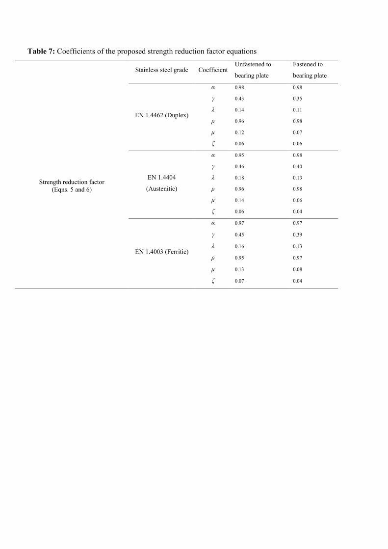
Table 7: Coefficients of the proposed strength reduction factor equations
Stainless steel grade Coefficient Unfastened to
bearing plate
Fastened to
bearing plate
Strength reduction factor
(Eqns. 5 and 6)
EN 1.4462 (Duplex)
α 0.98 0.98
γ 0.43 0.35
λ 0.14 0.11
ρ 0.96 0.98
µ 0.12 0.07
ζ 0.06 0.06
EN 1.4404
(Austenitic)
α 0.95 0.98
γ 0.46 0.40
λ 0.18 0.13
ρ 0.96 0.98
µ 0.14 0.06
ζ 0.06 0.04
EN 1.4003 (Ferritic)
α 0.97 0.97
γ 0.45 0.39
λ 0.16 0.13
ρ 0.95 0.97
µ 0.13 0.08
ζ 0.07 0.04

Table 8: Statistical analysis of strength reduction factor
a: Duplex stainless steel grade
Statistical parameters
Centred circular web opening
R (FEA) / Rp
Offset circular web opening
R (FEA) / Rp
Unfastened
to bearing plate
Fastened
to bearing plate
Unfastened
to bearing plate
Fastened
to bearing plate
Number of data 69 69 84 81
Mean, Pm 0.99 1.00 1.04 1.04
Coefficient of variation, Vp 0.09 0.08 0.04 0.05
Reliability index, β 2.62 2.69 2.97 2.95
Resistance factor, φ 0.85 0.85 0.85 0.85

b: Austenitic stainless steel grade
Statistical parameters
Centred circular web opening
R (FEA) / Rp
Offset circular web opening
R (FEA) / Rp
Unfastened
to bearing plate
Fastened
to bearing plate
Unfastened
to bearing plate
Fastened
to bearing plate
Number of data 69 69 66 69
Mean, Pm 1.00 1.00 1.00 1.00
Coefficient of variation, Vp 0.09 0.08 0.01 0.01
Reliability index, β 2.66 2.70 2.85 2.85
Resistance factor, φ 0.85 0.85 0.85 0.85
c: Ferritic stainless steel grade
Statistical parameters
Centred circular web opening
R (FEA) / Rp
Offset circular web opening
R (FEA) / Rp
Unfastened
to bearing plate
Fastened
to bearing plate
Unfastened
to bearing plate
Fastened
to bearing plate
Number of data 69 69 66 69
Mean, Pm 1.00 1.00 1.00 1.00
Coefficient of variation, Vp 0.10 0.08 0.01 0.01
Reliability index, β 2.62 2.70 2.85 2.85
Resistance factor, φ 0.85 0.85 0.85 0.85

Figure Captions:
Figure 1: Photograph of cold-formed stainless steel lipped channel-sections with circular
web openings after Lawson et. al. (2015)
Figure 2: End-one-flange (EOF) loading condition after Lian et al. (2016c,d)
(a) Circular web opening centred under bearing plate
(b) Circular web openings offset from bearing plate
Figure 3: Experimental analysis of cold-formed steel lipped channel-sections under end-
one-flange (EOF) loading condition for the case of flange unfastened to bearing plate after
Lian et al. (2016c,d);
(a) Centred circular web opening
(b) Offset circular web opening
Figure 4: Definition of symbols
Figure 5: Finite element model of cold-formed steel lipped channel-sections under end-one-
flange (EOF) loading condition for the case of flange unfastened to bearing plate after Lian
et al. (2016c,d);
(a) Centred circular web opening
(b) Offset circular web opening
Figure 6: Comparison of finite element analysis and experimental results with Lian et al.
(2016c,d)
(a) Centred circular web opening for the case of flange unfastened to bearing plate
(b) Offset circular web opening for the case of flange fastened to bearing plate
Figure 7: Variation in reduction factors for C142 section for the case of flange unfastened to
bearing plate
(a) a/h for centered circular web opening
(b) x/h for offset circular web opening
Figure 8: Comparison of strength reduction factor for C142 section for the case of flange
unfastened to bearing plate
(a) with centered circular web opening
(b) with offset circular web opening
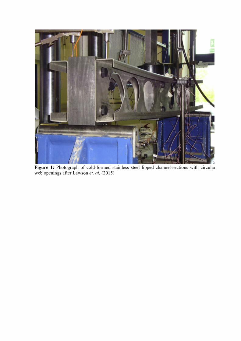
Figure 1: Photograph of cold-formed stainless steel lipped channel-sections with circular
web openings after Lawson et. al. (2015)

(a) Circular web opening centred under bearing plate
(b) Circular web openings offset from bearing plate
Figure 2: End-one-flange (EOF) loading condition after Lian et al. (2016c,d)

(a) Centred circular web opening
(b) Offset circular web opening
Figure 3: Experimental analysis of cold-formed steel lipped channel-sections under end-
one-flange (EOF) loading condition for the case of flange unfastened to bearing plate after
Lian et al. (2016c,d)

Figure 4: Definition of symbols
(a) Centred circular web opening
(b) Offset circular web opening
Figure 5: Deformed shape predicted from finite element analysis of cold-formed steel
lipped channel-sections under end-one-flange (EOF) loading condition for case of flange
unfastened to bearing plate after Lian et al. (2016c,d)
y
z x
y
z x
(a) Centred circular web opening for the case of flange unfastened to bearing plate
0
1
2
3
4
5
6
7
8
0 2 4 6 8 10 12 14
Ap
pli
ed l
oad
per
web
(kN
)
Displacement (mm)
A0.4-Test
A0.6-FEA A0.6-Test
A0-FEA
A0-Test
A0.4-FEA

(b) Offset circular web opening for the case of flange fastened to bearing plate
Figure 6: Comparison of finite element results and experimental test results (Lian et al.
2016c,d)
0
1
2
3
4
5
6
7
8
0 2 4 6 8 10 12 14
Ap
pli
ed l
oad
per
web
(kN
)
Displacement (mm)
A0.4-Test
A0-TestA0-FEA
A0.4-FEA
(a) a/h for centered circular web opening
(b) x/h for offset circular web opening
Figure 7: Variation in reduction factors for C142 section for the case of flange unfastened to
bearing plate
(a) Centered circular web opening
(b) Offset circular web opening
Figure 8: Comparison of strength reduction factor for C142 section for the case of flange
unfastened to bearing plate
0.0
0.2
0.4
0.6
0.8
1.0
1.2
1.4
0 0.1 0.2 0.3 0.4 0.5 0.6 0.7 0.8 0.9 1
R/R
p
a/h Ratio
Duplex ○ - R (FEA) / Rp (Eq. 5)
Ferritic + - R (FEA) / Rp (Eq. 5)
Austenitic × - R (FEA) / Rp (Eq. 5)
0.6
0.8
1.0
1.2
1.4
0.0 0.1 0.2 0.3 0.4 0.5 0.6 0.7 0.8 0.9 1.0
R/R
p
a/h Ratio