design of connecting rod of air compressor: a … · design of connecting rod of air compressor: a...
TRANSCRIPT

ISSN: 2455-2631 © July 2019 IJSDR | Volume 4, Issue 7
IJSDR1907063 International Journal of Scientific Development and Research (IJSDR) www.ijsdr.org 370
DESIGN OF CONNECTING ROD OF AIR COMPRESSOR: A
TOPOLOGY OPTIMIZATION APPROACH
1Aishwarya B. Dhavale, 2Dr.P.M.Bagade
Department of Mechanical Engineering, Padmabhushan Vasantdada
Patil Institute of Technology, Bavdhan,
Savitribai Phule Pune University, India
Abstract: To obtain optimized weight of connecting rod of an air compressor which can withstand the load acting on it due
to compressed gases. The connecting rod is used to convert the rotatory motion of electric motor to the oscillatory motion
of the piston. The rod is subjected to the cyclic loads of compression and tension. The optimized connecting rod with reduced
weight results in the reduced inertial forces in the system. The objective is to design and analysis the structural stress
distribution of connecting rod using real time condition during process. Depending upon loading condition FE analysis of
connecting rod can be done. Based upon loading gas pressure and compressor specification loading can be calculated. The
modeling of the connecting rod is done on Catia V5 and analysis work is done on ANSYS 19.2. The parameters like Von
misses stress, Von misses strain and displacement was obtained from ANSYS software which shows reduction in weight and
improvement in strength The overall results of the analysis are also validated by the analytical method and UTM machine.
Thus the process results in the optimized and effective connecting rod.
Keywords: Connecting Rod, weight, finite element analysis, Topology optimization.
I. INTRODUCTION
Positive displacement compressors are used to draw in and capture a volume of air in a chamber. Their function is to reduce the
volume of the chamber to compress the air. Air pressure is generated by rotating impellers in other types of compressors, positive
displacement is more common and includes the models used by homeowner, woodworkers, mechanics, and contractors. Here air
pressure is increased by reducing the size of the space that contains air. Most of the compressors which are run across doing this
job with a reciprocating piston. In reciprocating compressor a piston is used, which moves inside a cylinder, to compress the air.
When the piston moves down, the air is drawn in. When the piston moves up, the air is compressed. Air intake and exhaust are the
two valves used in an air compressor.
Fig. 1 Reciprocating Compressor
The function of connecting rod in compressors is to transmit the power from crankshaft to the piston to compress the air. The role
of connecting rod in the conversion of rotary motion into reciprocating motion. The lighter connecting rod and the piston will
result in greater compression and less vibration as reciprocating weight is less.
Fig.2 Air Compressor

ISSN: 2455-2631 © July 2019 IJSDR | Volume 4, Issue 7
IJSDR1907063 International Journal of Scientific Development and Research (IJSDR) www.ijsdr.org 371
There are different types of production and material application methods used in the creation of connecting rods. The common types
of connecting rods material are steel and aluminum. The common types of manufacturing processes are casting, forging and
powdered metallurgy. A connecting rod consists of a pin-end, a shank section, and a crank-end. Pin-end and crank-end pinholes at
the upper and lower ends are drilled or machined to permit the accurate fitting of bearings.
Fig.3 Connecting Rod
The optimization of the connecting rod had already started as the early year 1983 by Webster and his team. Nowadays customer
and industries are looking for the best from the best. That’s why optimization is considered important in industries. Optimization
of the component is to reduce the time of production of a component, make it durable and cheaper.
II. LITERATURE REVIEW
[1] J.Chao [2018] analysed the failure of an oblique split connecting rod with serrated joint faces in a medium-speed gas engine at
a cogeneration plant. Engine failure occurred suddenly after 20,000 h of service by malfunctioning without the engine control
system providing an automatic engine shutdown signal. The failure affected two trains, which were mounted on the same crankpin
and to the crankshaft itself. The analysis was concentrated on the connecting rod in which fatigue features on the fracture surface
were observed. The location of the fracture in this connecting rod occurred close to the lower joint within the vicinity of the
connecting rod axis. Beach marks on the fracture surfaces indicated that the crack initiated from the big end internal surface,
approximately 5 mm from the oil groove, away from any geometric stress concentration. To determine the fracture cause, a material
characterization and an analysis of the material state near the fracture initiation point was conducted. The analysis was extended to
the bearing shells of the damaged trains and to the bearing shells of a connecting rod that did not fail. The results suggest that the
mechanism of failure of the engine may have probably been fretting-fatigue produced by the relative micro-movements between
the bearing back and the housing bore.
[2]S.V.UmaMaheswara,T.V.Hanumanta Rao, K. Satyanarayana, B. Nagaraju [2018]. Connecting Rod is an important
component in reciprocating type of I.C engines. The chances of fatigue failure in connecting rod are higher when it is subjected to
alternative compressive and tensile stresses in a cycle of the engine. More over the connecting rod is also subjected to buckling
stress as it acts as a column. Hence, it is necessary to determine the fatigue life of the existing connecting rod materials and also
look for alternative materials. Using the output of a test, which was conducted on computerized variable compression ratio (V.C.R),
Kirloskar Diesel Engine equipment provided with a pressure transducer, kinematic and dynamic analysis of a connecting rod was
carried out at a compression ratio of 16.5. Further the results of Dynamic analysis were utilized for carrying out Quasi-Dynamic
stress analysis. We embarked on performing the kinematic and dynamic analysis of connecting rod using MATLAB at a
compression ratio of 16.5, 17.5 and 18.5 and also at four different critical crank angles with the existing materials namely Forged
Steel, Aluminum Alloy and Titanium alloy. Further, the analysis was performed by using ANSYS workbench for determining the
Vonmises stresses, Deformations, Life and Factor of safety.
[3] C. Juarez, F. Rumiche, A. Rozas, J. Cuisano, P. Lean [2016] This paper presents the results of a failure of analysis connecting
rod of the generator, the generator is a device which converts mechanical energy into electrical and fuel used to run the generator
is diesel The study and analysis included an analysis of the connecting rod material as well as the fracture zone. visual inspection,
fractography, magnetic particle inspection, chemical analysis, tensile and hardness testing, metallographic, and microanalysis were
the experiment and testing techniques performed. AISI/SAE 4140 low alloy steel was used for fabrication of connecting rod, as per
application appropriate chemical composition, mechanical properties, and microstructure were selected. After the analysis
connecting rod was fractured at the body in a section close to the head; the origin of the fracture was located at the con-rod lubrication
channel from a machining tool, embedded in its surface as a result of a deficient manufacturing process. The analyzed area acted as
a nucleation site for cracks that propagate through the connecting rod at section by a fatigue mechanism, reducing its section and
finally producing its catastrophic failure.
[4] G Gopala, Dr L Suresh Kumar, K Vijaya Bahskar Reddy, M Uma MaheshwaraRaod , G Srinivasulu [2017] The paper
deals with the study of an assembly of the Piston, Connecting rod and Crankshaft of a four-wheeler petrol engine. The components
of the assembly have to be rigid and the assembly has to move as a mechanism. Hence, Rigid-body and flexible body analysis were
ISSN: 2455-2631 © July 2019 IJSDR | Volume 4, Issue 7
IJSDR1907063 International Journal of Scientific Development and Research (IJSDR) www.ijsdr.org 372
included. So, the forces in the components as the engine reciprocates have to be calculated and these forces are used to calculate
the dynamic stresses in the component of interest i.e. the connecting rod. It is proposed to replace with two new sets of materials
for the components of the assembly and check the parameters by performing the static, dynamic and thermal analysis In this project,
the main parts of the assembly i.e. engine piston, connecting rod and crankshaft are modeled and assembled as per the given design.
And the Finite Element Analysis is done in Ansys. The meshing is done in Hyper Mesh.
[5] K. Bari, A. Rolfe, A. Christofi, C. Mazzuca and K.V. Sudhakar [2017] This research paper explains an investigation of the
failure of connecting rod from a motorcycle engine considering the root cause of and mechanisms which leads to its premature
failure. Including the root cause, the other task from this study was to improve the existing designs or methods to avoid failures in
the future. These results were validated using a finite element analysis (FEA) simulation. A Scanning Electron Microscope was
used for investigating the mechanisms of fracture modes, optical microscopy for studying the microstructures and visual inspection
were primarily utilized to determine the root cause of the failure. In conclusion, it was determined that the root cause for the
premature failure of the connecting rod was the presence of scale build-up inclusions, which led to micro cracking during fatigue
loading of the component.
[6] Zhou Shia, ShuqingKoua[2018]Quality defects of fracture surface are easily produced in the fracture splitting process of the
connecting rod. Presently, the resulting mechanism of this type of defect is lacking in evidence and there is no effective control
method. Based on fracture mechanics and the actual production, this study simulates the process of connecting rod fracture splitting
using finite element method. Three-dimensional crack propagation state is described, and the stress and deformation of the crack
tip are analyzed. The essence of the fracture surface defects, such as drop dregs, steps, and crack bifurcations, are mainly due to the
change of the crack path and structure during crack propagation. These defects mainly occur at the boundary positions of the fracture
surface such as bolt hole and end faces, which is due to the boundary’s stress and deformation characteristics of the fracture surface.
The boundary is in the plane stress state, the crack tip undergoes shear deformation and has a large plastic zone which leads to a
severe twist of the crack tip opening angle. Fracture-splitting defects were the result obtained by the cause of the crack propagation
path to be twisted and bent.
[7] Slavko Rakić, Dr UgljesaBugaric[2017]This paper presents failure analysis of the connecting rod used in a 12-cylinder diesel
engine set on a special vehicle. The connecting rod was fractured during the engine test in laboratory conditions. Chemical and
metallographic analysis, as well as mechanical testing, have confirmed that the material properties of the connecting rod met the
requirements of standard specification and technical documentation. Stress state of the connecting rod under maximum load was
evaluated by performing Linear finite element (FE) analysis. The output of the FE analysis indicated that the position of the fracture
is consistent with the zone of highest stress. Fractographic analysis has not been able to reveal the main cause of the mechanism of
fracture due to the substantially damaged fracture surface. Inadequate machining, absence of polishing and highest stress in the
region of fracture were identified as the main causes of failure. Hence, the engine was working at maximum load for a longer period
of time that also led to the breakage of the connecting rod.
[8] D.Gopinatha ,Ch.V.Sushma[2015] Every vehicle that uses an internal combustion engine requires at least one connecting rod
depending upon the number of cylinders in the engine. It undergoes high cyclic loads of the order of 108 to109 cycles, which range
from high compressive loads due to combustion, to high tensile loads due to inertia. Therefore, durability of the component is of
critical importance. Because of these factors, the connecting rod has been used as the topic of research for different aspects mainly
production, materials, performance simulation, etc. The main problem definition of research was to explore weight reduction and
create better opportunities for the production of forged steel, aluminium and titanium connecting rods. This has entailed performing
a detailed load analysis. Hence, this study has dealt with two main subjects, first, static load stress analysis of the connecting rod
for three different materials, and second, optimization for the weight of forged steel connecting rod. In this research, firstly a proper
geometrical model was developed using CATIA.
[9] Mohammed Mohsin Ali Ha [2015]The Connecting rod transfers the load on the piston to the crank by causing the latter to
turn, thus converting the reciprocating motion of the piston into a rotary motion of the crankshaft. Connecting rods are subjected to
forces which are generated by mass and fuel combustion. The connecting rod is modeled using CATIA software and FE analysis is
carried out using ANSYS Software. Load distribution plays an important role in fatigue life of the structure. Bush failure changes
the loading direction and distribution. The present study is concentrated around the fatigue life due to concentrated load and cosine
type load distribution on the bigger end.
[10]ZhuJun-chao[2016] Dynamic lubrication analysis of connecting rod is a very complex problem. Some factors have a great
effect on lubrication, such as clearance, oil viscosity, oil supplying hole, and surface roughness. This work establishes the EHD
characteristic of bearing and bush to analyze the peak oil film pressure, min oil film thickness and nodes force with consideration
of deformation and cavitation. Then connecting rod components are created to calculate the stress distribution with consideration
of film lubrication or not. Finally, contract the results of two conditions. The results show that: the stress distribution of two
conditions are different in individual positions, but the stress calculation method considering the oil film lubrication is more
consistent with the actual working conditions.

ISSN: 2455-2631 © July 2019 IJSDR | Volume 4, Issue 7
IJSDR1907063 International Journal of Scientific Development and Research (IJSDR) www.ijsdr.org 373
III. PROBLEM DEFINITION
Each day consumers are looking for the best from the best. That’s why material optimization is really important in the industry.
Material Optimization of the component is to make less time to produce the product that is stronger, lighter and less cost. Influence
of design and weight on performance of the connecting rod. Hence, it is an effect on the manufacture of credibility. The tensile and
compressive stresses are produced due to pressure, and bending stresses are produced due to centrifugal effect & eccentricity. Hence
connecting rods are designed generally of I-section so that maximum rigidity with minimum weight. Significant increments in
weight and performance can be achieved by changing the structural design and also material.
Pneumatic Compressors are subjected to less dynamic loads as compared to automotive engines. Exercise work has been done
on automotive Connecting Rods in terms of thermal and structural optimization.
IV. OBJECTIVES
The main aim of the project is to determine the Von Misses stresses, Shear stresses, and Equivalent Alternating stress,
Total Deformation, Fatigue Analysis and Material Optimization in the existing Connecting rod.
The result comparison between the Aluminum material and Plastic material of connecting rod.
In this Project, the static FEA of the connecting rod has been performed by the use of the software. Hence work can be
extended further to study the effect of loads on the connecting rod under dynamic conditions.
Experimental stress analysis of Model using Strain gauging & lifting load applied through UTM.
Experimental buckling analysis can also be used to calculate the stresses which will provide more reasons to compare the
different values obtained.
Comparative analysis between FEA & Experimental results.
V. METHODOLOGY
1. Modeling current connecting rod.
2. Analyzing for stresses and deformation.
3. Topological optimization for the model.
4. Results from topological optimization will be implementedon the existing model
5. Analyzing for stresses and deformation on the optimized model.
6. Machining the existing connecting rod of air compressor as per the optimization result.
7. Finding high strain portion from CAE software.
8. Mounting strain gauge on the same portion.
9. Preparing fixtures to hold the connecting rod for experimental testing.
10. Correlating results of both CAE and experimental.
SPECIFICATIONS OF COMPRESSOR:
Company of Compressor = Speed
H.P.= 7.5
RPM = 640
Tank in Size = 21*52 (In Inch) = 290 PSI
Working Pressure = 183 PSI = 1.26 MPa
Bore*Stroke = 70*70 (In mm)
ISSN: 2455-2631 © July 2019 IJSDR | Volume 4, Issue 7
IJSDR1907063 International Journal of Scientific Development and Research (IJSDR) www.ijsdr.org 374
Piston Displacement = 27mm
VI. BASIC CALCULATION
Area = l*b = 3.2*3.8 mm2
Pressure = Force / Area
Force = Pressure*Area = 1.26*1216
= 1532.16N
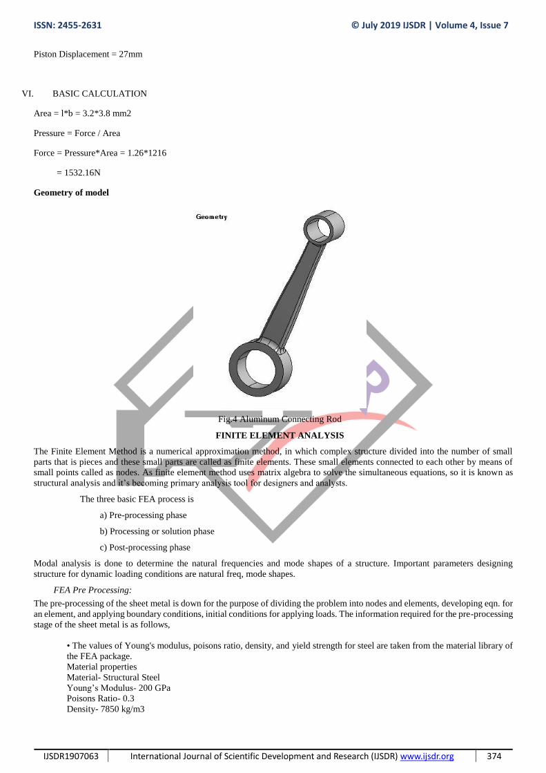
Geometry of model
Fig.4 Aluminum Connecting Rod
FINITE ELEMENT ANALYSIS
The Finite Element Method is a numerical approximation method, in which complex structure divided into the number of small
parts that is pieces and these small parts are called as finite elements. These small elements connected to each other by means of
small points called as nodes. As finite element method uses matrix algebra to solve the simultaneous equations, so it is known as
structural analysis and it’s becoming primary analysis tool for designers and analysts.
The three basic FEA process is
a) Pre-processing phase
b) Processing or solution phase
c) Post-processing phase
Modal analysis is done to determine the natural frequencies and mode shapes of a structure. Important parameters designing
structure for dynamic loading conditions are natural freq, mode shapes.
FEA Pre Processing:
The pre-processing of the sheet metal is down for the purpose of dividing the problem into nodes and elements, developing eqn. for
an element, and applying boundary conditions, initial conditions for applying loads. The information required for the pre-processing
stage of the sheet metal is as follows,
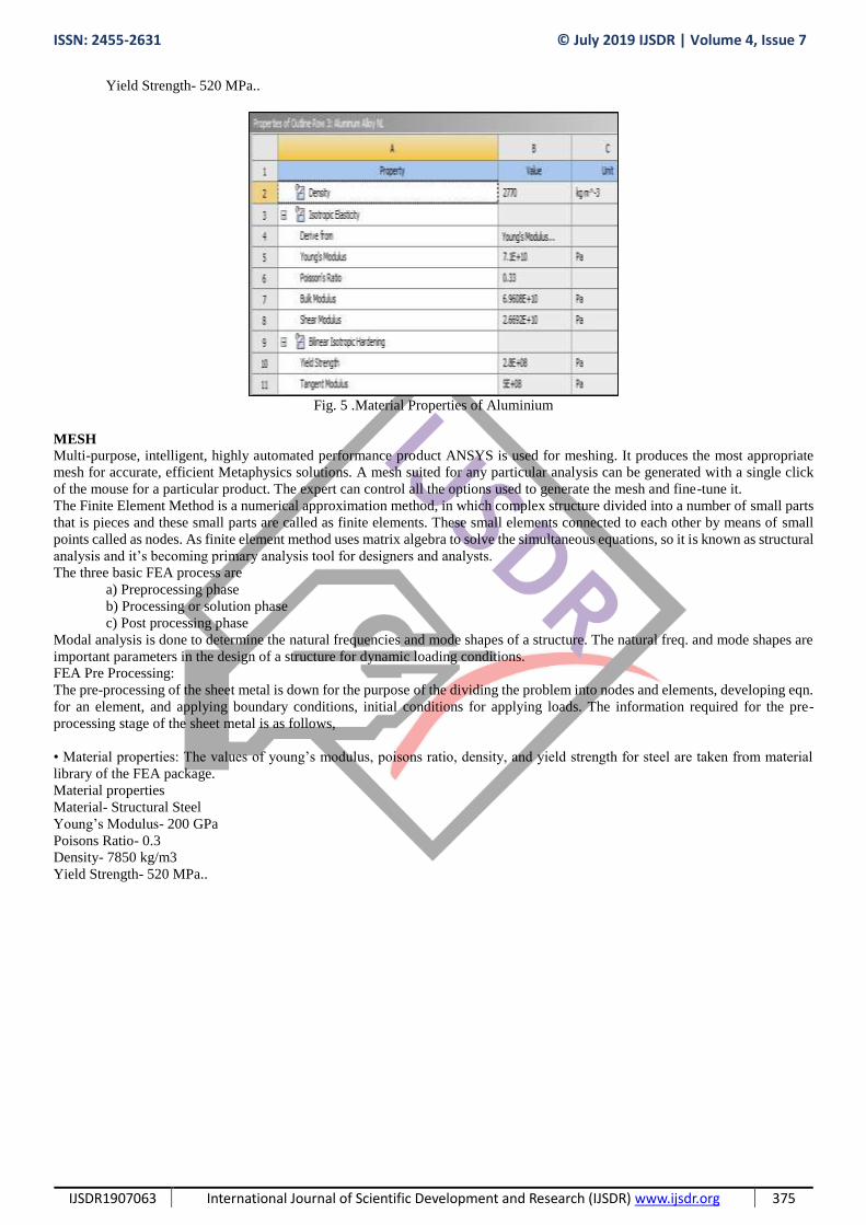
• The values of Young's modulus, poisons ratio, density, and yield strength for steel are taken from the material library of
the FEA package.
Material properties
Material- Structural Steel
Young’s Modulus- 200 GPa
Poisons Ratio- 0.3
Density- 7850 kg/m3
ISSN: 2455-2631 © July 2019 IJSDR | Volume 4, Issue 7
IJSDR1907063 International Journal of Scientific Development and Research (IJSDR) www.ijsdr.org 375
Yield Strength- 520 MPa..
Fig. 5 .Material Properties of Aluminium
MESH
Multi-purpose, intelligent, highly automated performance product ANSYS is used for meshing. It produces the most appropriate
mesh for accurate, efficient Metaphysics solutions. A mesh suited for any particular analysis can be generated with a single click
of the mouse for a particular product. The expert can control all the options used to generate the mesh and fine-tune it.
The Finite Element Method is a numerical approximation method, in which complex structure divided into a number of small parts
that is pieces and these small parts are called as finite elements. These small elements connected to each other by means of small
points called as nodes. As finite element method uses matrix algebra to solve the simultaneous equations, so it is known as structural
analysis and it’s becoming primary analysis tool for designers and analysts.
The three basic FEA process are
a) Preprocessing phase
b) Processing or solution phase
c) Post processing phase
Modal analysis is done to determine the natural frequencies and mode shapes of a structure. The natural freq. and mode shapes are
important parameters in the design of a structure for dynamic loading conditions.
FEA Pre Processing:
The pre-processing of the sheet metal is down for the purpose of the dividing the problem into nodes and elements, developing eqn.
for an element, and applying boundary conditions, initial conditions for applying loads. The information required for the pre-
processing stage of the sheet metal is as follows,
• Material properties: The values of young’s modulus, poisons ratio, density, and yield strength for steel are taken from material
library of the FEA package.
Material properties
Material- Structural Steel
Young’s Modulus- 200 GPa
Poisons Ratio- 0.3
Density- 7850 kg/m3
Yield Strength- 520 MPa..

ISSN: 2455-2631 © July 2019 IJSDR | Volume 4, Issue 7
IJSDR1907063 International Journal of Scientific Development and Research (IJSDR) www.ijsdr.org 376
Fig. 6. Meshing of Aluminium Connecting Rod
Fig. 7. Meshing of Optimized Model
Boundary Condition
A boundary condition of the model is the setting of known value for displacement or an associated load. Either the load or the
displacement can be set for a particular node.The most used types of loading available in FEA study include force, pressure, and
temperature. These can be applied to any points, surfaces, edges, nodes, and elements or remotely offset from a feature of part,
assembly or product.

ISSN: 2455-2631 © July 2019 IJSDR | Volume 4, Issue 7
IJSDR1907063 International Journal of Scientific Development and Research (IJSDR) www.ijsdr.org 377
Fig.8 Boundary Condition on Aluminum` Connecting Rod
Fig. 9 Boundary Condition of Optimized Model
Total Deformation
The total deformation & directional deformation are general terms in finite element methods irrespective of software being used.
Directional deformation can be used as the displacement of the system in any particular axis or user-defined vector. Total
deformation can be defined vector sum all directional displacements of the systems or in space.

ISSN: 2455-2631 © July 2019 IJSDR | Volume 4, Issue 7
IJSDR1907063 International Journal of Scientific Development and Research (IJSDR) www.ijsdr.org 378
Fig.10. Total Deformation of Connecting Rod
Fig. 11. Total Deformation of Optimized Model
Equivalent Stress
Equivalent stress is equivalent to the principal stresses by the equation
Equivalent stress is mostly used in designing product or part because it allows any arbitrary three-dimensional stress state to be
represented as a single positive stress value. Equivalent stress is represented as the maximum equivalent stress failure theory used
to predict any yielding in a ductile material.

ISSN: 2455-2631 © July 2019 IJSDR | Volume 4, Issue 7
IJSDR1907063 International Journal of Scientific Development and Research (IJSDR) www.ijsdr.org 379
The von Mises or equivalent strain εe is expressed as:
Where:
ν' = effective Poisson's ratio
Fig. 12 Equivalent Stress of Connecting Rod
Fig. 13. Equivalent Stress of Optimized Connecting Rod

ISSN: 2455-2631 © July 2019 IJSDR | Volume 4, Issue 7
IJSDR1907063 International Journal of Scientific Development and Research (IJSDR) www.ijsdr.org 380
Minimum principal strain
Fig. 14. Minimum Principle Strain of Connecting Rod
Fig. 15. Minimum Principle Strain of Optimized Connecting Rod
VII. EXPERIMENTAL TESTING
Universal tester is also known as a universal testing machine (UTM which can be used to test the tensile strength and compressive
strength of materials. An earlier name for a tensile testing machine is a tensometer. It can perform many standard tensile and
compression tests on materials, components, and structures (in other words, that it is versatile) hence named as the "universal".
The set-up and usage are detailed in a test method, often published by a standards organization. This specifies the sample
preparation, fixturing, gauge length (the length which is under study or observation), analysis, etc.
The specimen is placed in the machine between the grips and an extensometer if required can automatically record the change in
gauge length during the test. The machine itself can record the displacement between its crossheads on which the specimen is held
even if an extensometer is not fitted. UTM not only records the change in length of the specimen but also all other extending /
elastic components of the component and its drive systems including any slipping of the specimen in the grips.

ISSN: 2455-2631 © July 2019 IJSDR | Volume 4, Issue 7
IJSDR1907063 International Journal of Scientific Development and Research (IJSDR) www.ijsdr.org 381
Once the machine is operated it starts to apply an increasing load as per input on the specimen. The controls system and its associated
software record the load and extension or compression of the specimen throughout the tests.
Fig.16. Experimental Testing
VIII. RESULT & CONCLUSION
The Connecting Rod is optimized. The weight of Connecting rod before optimization is 234.6g and connecting rod after
optimization is 133g. So, the Optimization is done. The strain value obtained after the analysis result is 3.0769 and the strain value
obtained after the experimental testing is 3.267. So, the results are nearly equal. So, the results are validated.
REFERENCES:
[1] J.Chao, “Fretting-fatigue induced failure of a connecting rod” ScienceDirect, Volume 96,February 2019.
[2] S.V.UmaMaheswara,T.V.HanumantaRao,K. Satyanarayana, B. Nagaraju , “Fatigue Analysis of Sundry I.C Engine
Connecting Rods” ScienceDirect, Volume 5, Issue 2, Part 1,2018, Pages 4958-4964.
[3] C. Juarez, F. Rumiche, A. Rozas, J. Cuisano, P. Lean ,“Failure analysis of a diesel generator connecting rod” ScienceDirect,
Volume 7, October 2016, Pages 24-31.
[4] G Gopala, Dr L Suresh Kumar, K Vijaya Bahskar Reddy, M Uma MaheshwaraRaod , G Srinivasulu, “Analysis of Piston,
Connecting rod and Crank shaft assembly”,ScienceDirect, Volume 4, Issue 8, 2019, Pages 7810-7819.
[5] K. Bari, A. Rolfe, A. Christofi, C. Mazzuca and K.V. Sudhakar,“Forensic,Investigation of a Failed Connecting Rod from a
Motorcycle Engine”, Science Direct, Volume 9, October 2017, Pages 9-16.
[6] Zhou Shia, Shuqing Koua, “Analysis of quality defects in the fracture surface of fracture splitting connecting rod based on
three-dimensional crack growth” Science Direct, Volume 10, September 2018, Pages 1022-1029.
[7] Slavko Rakić, Dr UgljesaBugaric , “Failure analysis of a special vehicle engine connecting rod”
Volume 17, September 2017, Pages 98-109.
[8] D.Gopinatha,Ch.V.Sushma,“Design & Optimization of Four-Wheeler Connecting Rod Using Finite Element
Analysis”,Volume 2, Issues 4–5, 2015, Pages 2291-2299
[9] Mohammed Mohsin Ali Ha, Mohamed Haneef “Analysis of Fatigue Stresses on Connecting Rod Subjected to Concentrated
Loads at The Big End” ,Volume 2, Issues 4–5, 2015, Pages 2094-2103.
[10] Zhu Jun-chao, Zhu Han-hua, Fan Shi-dong, Xue Liang-jun, Li You-feng, “A Study on the influence of Oil film lubrication to
the Strength of Engine Connecting Rod Components”,ISSN