design of distillation trays
TRANSCRIPT
Tray Design Techniques at Low Liquid Load Conditions
Daniel R. Summers, P.E.
Sulzer Chemtech USA, Inc. Tulsa, OK 74107
Andrew W. Sloley, P.E.
VECO USA, Inc. Bellingham, WA 98225
Presented at the AIChE Spring Meeting
Distillation Symposium April 23, 2006
Orlando, Florida
Copyright © 2006 by Sulzer Chemtech USA, Inc. & VECO USA, Inc. Unpublished
The AIChE shall not be responsible for statements or opinions contained in its publications
We (as an industry) have a difficult time describing criteria for minimum liquid load in many trayed
distillation applications. At present most people look at two criteria for standard downcomers: minimum
weir loading and spray (blowing) factor. For truncated downcomers a third factor deals with keeping the
downcomer sealed against vapor by-pass. The problem is that the first two are ill defined and little is
understood about them.
Specific services including wash sections of towers, upper sections of low pressure distillation towers and
separation of high boilers all can lead to tray designs that have very low liquid loads. Today many of these
applications use random or structured packings as the preferred tower internal. However, as engineers, our
job is to find economical solutions to problems. Many times the economical solution may still be trays.
This paper is intended to address this issue and help define a design approach with Picket Fence outlet weirs
that can accommodate low liquid load tray design.
Previously, we stated(5), there are low liquid rates that result in trays operating in the spray and/or blowing
regime. "Lack of Liquid on the tray may seem difficult to understand, as the outlet weir keeps a liquid
pool on the tray. How could the tray not have enough liquid?" Many people have a difficult time
describing exactly what minimum liquid load is for trayed towers. As the authors understand it, there are
two criteria at present: minimum weir loading and spray (blowing) factor. The addition of picket fence
weirs to retain more of the liquid droplets over the tray is the most common method to extend a tray's
operating range. This paper is intended to address this issue and to provide a definition of how to design
Picket Fence outlet weirs that can accommodate low liquid load tray design.
According to FRI sieve tray observations(9), when reducing the liquid rate on a tray, below approximately
2.0 gpm/inch of weir loading, the vapor capacity must be reduced to maintain the same entrainment rate.
This has been repeated many times at FRI and they have observed this phenomenon for many devices other
than sieve trays. FRI has gone to "great lengths" of making their vapor capacity correlations have lower
maximum values at very low liquid loads. It is believed that this is a jet flood phenomenon and the
maximum vapor capacity equation is treated as such. This is really a misinterpretation on FRI's part and
that what is being observed, in reality, is a transition between the spray and froth regime as Kister and Haas
pointed out in 1988(10).
To better understand what is happening on a tray at low liquid loads you need to understand what is
happening at the outlet weir. As liquid rate drops on a tray, the froth height reduces. There is the famous
Francis Weir Formula for froth on a tray deck(6):
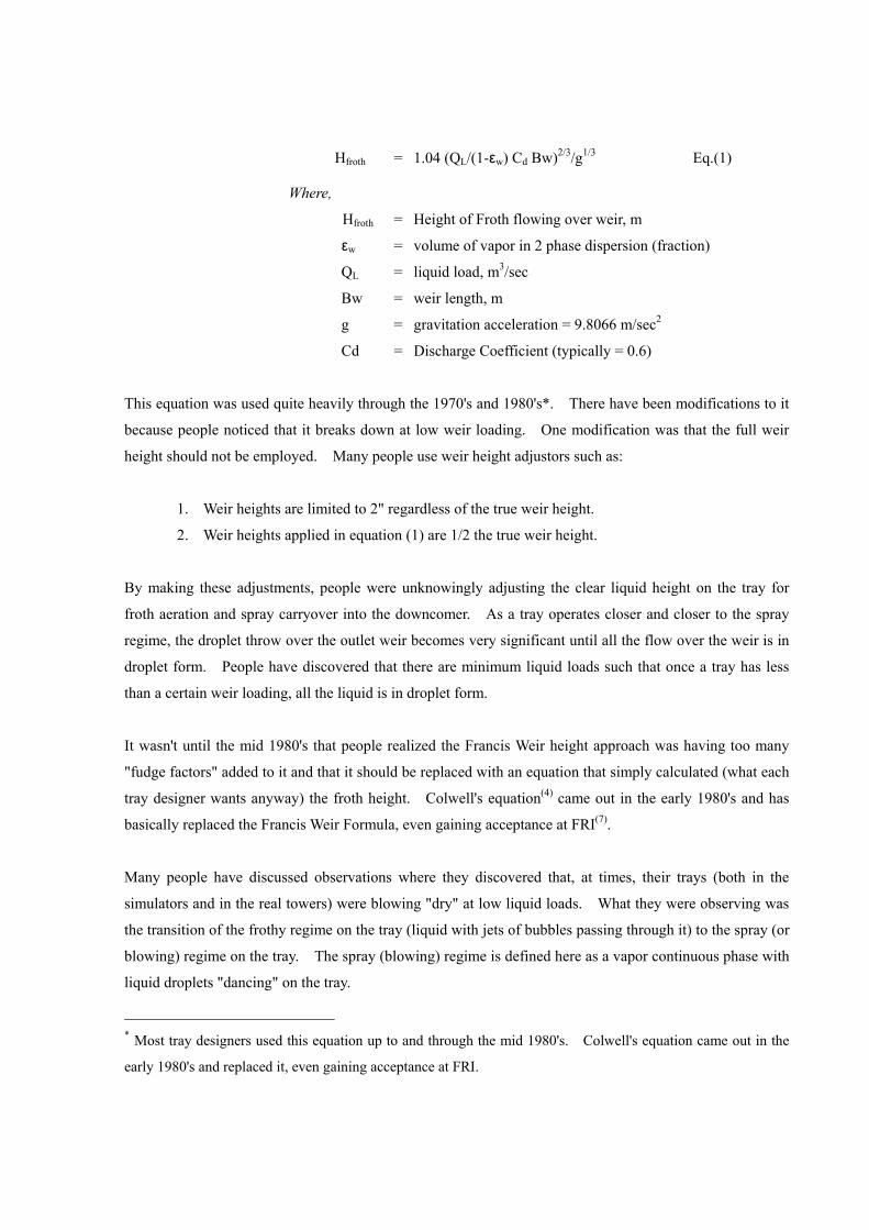
Hfroth = 1.04 (QL/(1-εw) Cd Bw)2/3/g1/3 Eq.(1)
Where,
Hfroth = Height of Froth flowing over weir, m
εw = volume of vapor in 2 phase dispersion (fraction)
QL = liquid load, m3/sec
Bw = weir length, m
g = gravitation acceleration = 9.8066 m/sec2
Cd = Discharge Coefficient (typically = 0.6)
This equation was used quite heavily through the 1970's and 1980's*. There have been modifications to it
because people noticed that it breaks down at low weir loading. One modification was that the full weir
height should not be employed. Many people use weir height adjustors such as:
1. Weir heights are limited to 2" regardless of the true weir height.
2. Weir heights applied in equation (1) are 1/2 the true weir height.
By making these adjustments, people were unknowingly adjusting the clear liquid height on the tray for
froth aeration and spray carryover into the downcomer. As a tray operates closer and closer to the spray
regime, the droplet throw over the outlet weir becomes very significant until all the flow over the weir is in
droplet form. People have discovered that there are minimum liquid loads such that once a tray has less
than a certain weir loading, all the liquid is in droplet form.
It wasn't until the mid 1980's that people realized the Francis Weir height approach was having too many
"fudge factors" added to it and that it should be replaced with an equation that simply calculated (what each
tray designer wants anyway) the froth height. Colwell's equation(4) came out in the early 1980's and has
basically replaced the Francis Weir Formula, even gaining acceptance at FRI(7).
Many people have discussed observations where they discovered that, at times, their trays (both in the
simulators and in the real towers) were blowing "dry" at low liquid loads. What they were observing was
the transition of the frothy regime on the tray (liquid with jets of bubbles passing through it) to the spray (or
blowing) regime on the tray. The spray (blowing) regime is defined here as a vapor continuous phase with
liquid droplets "dancing" on the tray.
* Most tray designers used this equation up to and through the mid 1980's. Colwell's equation came out in the
early 1980's and replaced it, even gaining acceptance at FRI.
The observation of when this phenomenon occurred has always been recorded by simulator operators as
when they could "see through the froth" and observe the tray deck. Armed with an enormous amount of
data, Union Carbide Corporation (UCC) came up with a vapor momentum force equation that helped define
when the vapor would "lift" the liquid from the tray deck. This work is NOT to be confused with the
system limit that FRI has established. What UCC had discovered is that hole velocity, hole size and height
of calculated clear liquid on the tray, all affect this transition. Equation 2.25 in Lockett's book was thus
developed(8) for sieve trays. This equation has been successfully applied at Sulzer Chemtech many times,
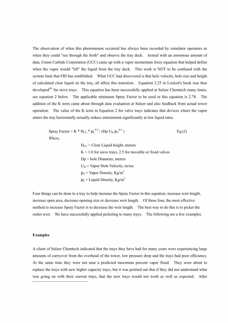
see equation 2 below. The applicable minimum Spray Factor to be used in this equation is 2.78. The
addition of the K term came about through data evaluation at Sulzer and also feedback from actual tower
operation. The value of the K term in Equation 2 for valve trays indicates that devices where the vapor
enters the tray horizontally actually reduce entrainment significantly at low liquid rates.
Spray Factor = K * HCL * ρL0.5 / (Dp UH ρV
0.5 ) Eq.(2)
Where,
HCL = Clear Liquid height, meters
K = 1.0 for sieve trays, 2.5 for movable or fixed valves
Dp = hole Diameter, meters
UH = Vapor Hole Velocity, m/sec
ρV = Vapor Density, Kg/m3
ρL = Liquid Density, Kg/m3
Four things can be done to a tray to help increase the Spray Factor in this equation; increase weir height,
increase open area, decrease opening size or decrease weir length. Of these four, the most effective
method to increase Spray Factor is to decrease the weir length. The best way to do this is to picket the
outlet weir. We have successfully applied picketing to many trays. The following are a few examples.
Examples
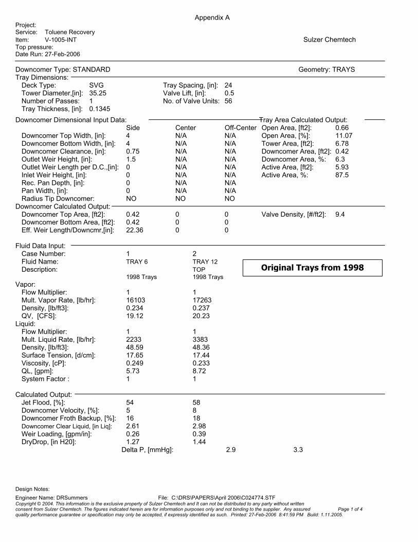
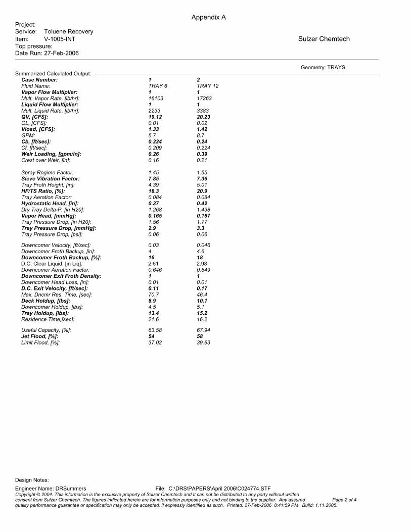
A client of Sulzer Chemtech indicated that the trays they have had for many years were experiencing large
amounts of carryover from the overhead of the tower, low pressure drop and the trays had poor efficiency.
At the same time they were not near a predicted maximum percent vapor flood. They were about to
replace the trays with new higher capacity trays, but it was pointed out that if they did not understand what
was going on with their current trays, that the new trays would not work as well as expected. After
looking at current operating information, it was discovered that the weir loading was extremely low, 0.26
gpm/in. The spray (blowing) factor (equation 2) was too low as well, 1.45. We determined that they
could simply add pickets to the outlet weir and the tower would work fine. This was enacted (we could
have sold a full set of new trays with picket fence weirs – but we were too honest), and they discovered
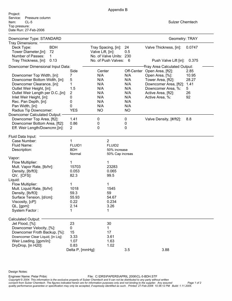
exactly how good the spray (blowing) factor equation really is. The rating sheets and weir layout is shown
Appendix A. This proves beyond doubt that the spray factor is real and can be applied to our trays.
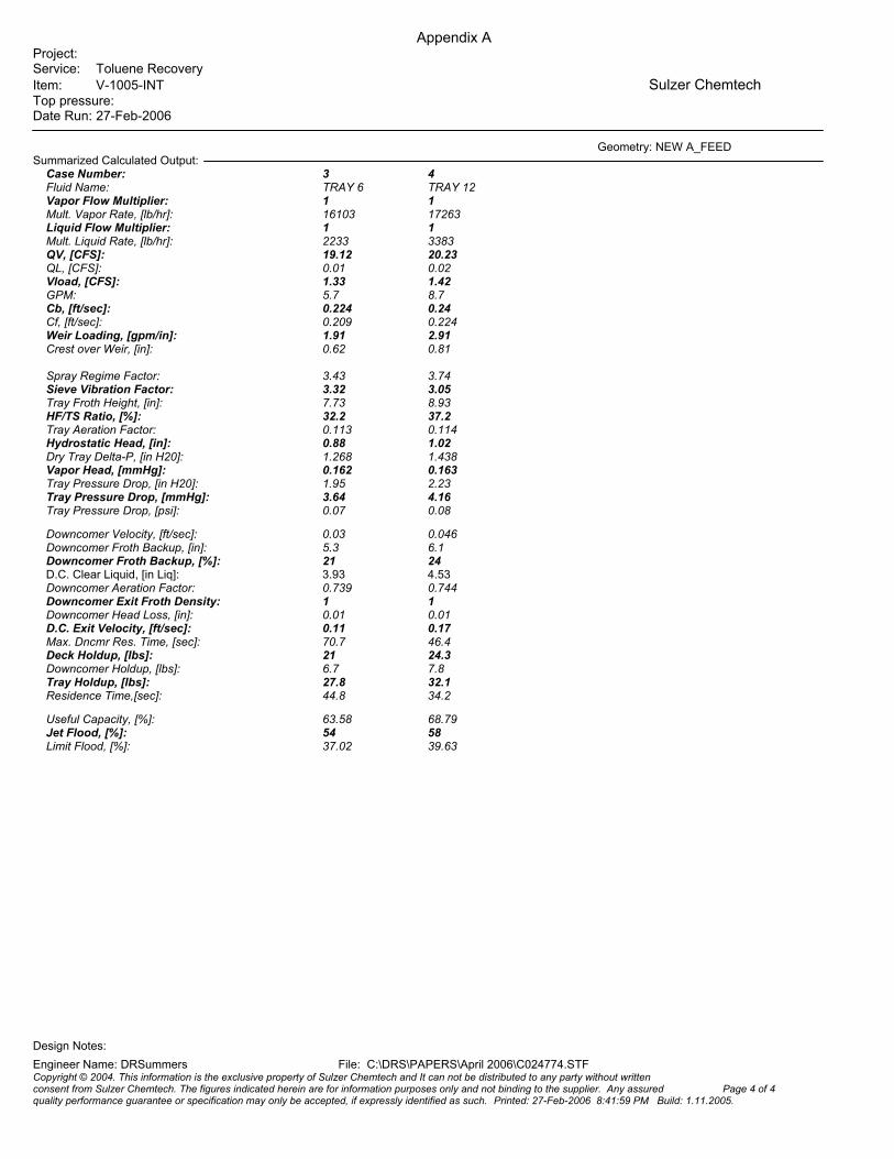
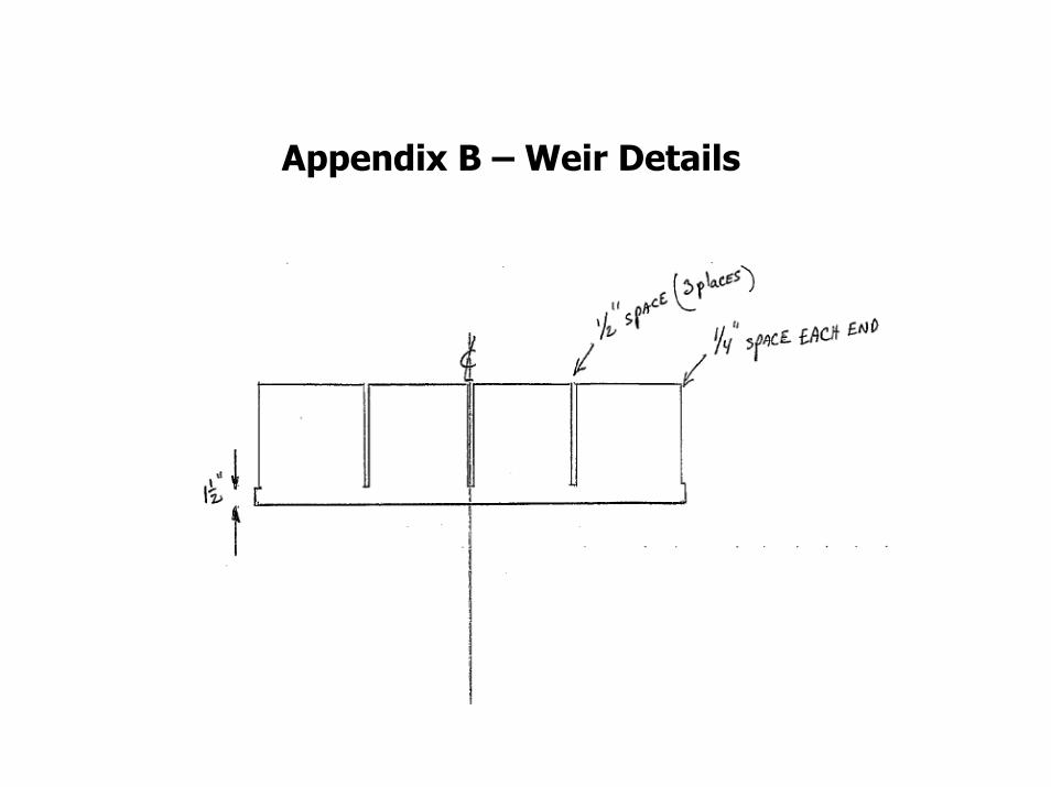
A second example comes from two existing stripper towers in a Caprolactam Plant where they are
experiencing carryover in the overhead and poor tray performance in this slightly fouling service. We
provided a design that reduced the weir length to only 5% of the chord length which is 95% picketing, see
photo in Figure 7. After startup the trays are performing excellently. Appendix B shows the tray rating
sheets after the revamp. The weir length was reduced such that the minimum weir loading is 1 gpm/inch
and the Spray Factor is well above minimum.
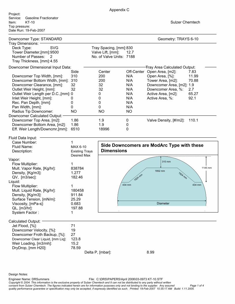
Another current example has recently started up. We replaced the outlet weirs on the 2-pass SVG trays in
a large 9.5 meter/13.1 meter diameter Oil Quench Tower. The client had complained that the existing trays
were entraining excessively. They also noticed that if they raised the operating pressure, the entrainment
went away. This led Sulzer to believe the trays were crossing over into the spray regime. A check of the
spray factor in Appendix C shows that the existing trays have a value of 1.44 which is well below the
allowable 2.78. Basically we used Lockett's equation to get more capacity from this tower. The spray
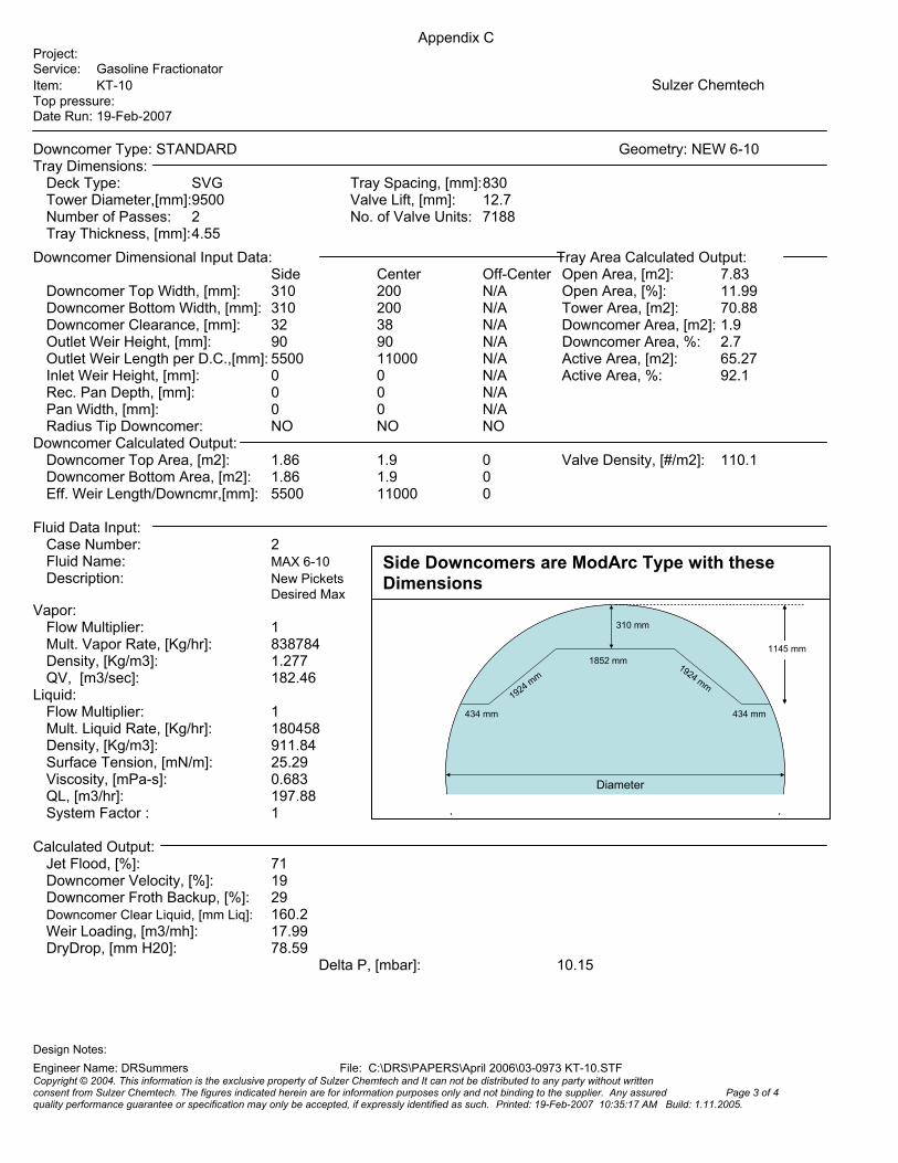
(blowing) factor was very low and by adding 42% picketing (58% effective weir length) the tower got the
desired 20% increase in capacity. Initial feedback is excellent from the client even though the Spray
Factor was only increased to 2.99. Note that for these two pass trays picketing was added to both the side
and center downcomer weir lengths. In addition, this reduction in weir length was not quite enough to
eliminate the spray factor. We could not reduce the weir length any more because the client indicated that
these trays have a tendency to foul. Subsequently, after checking the maximum allowable pressure drop
across the trays, the outlet weir height was also increased to increase the spray factor to acceptable levels.
Since the successful startup, it is important to note that the capacity of this low pressure Gasoline
Fractionator was actually increased by adding obstructions to the outlet weirs.
Design Criteria
Typically, people will establish minimum allowable effective weir lengths. ExxonMobil typically has
indicated that 70% blockages are acceptable and Dow has indicated that 80% blockages are acceptable.
Many people however indicate that 55% blockage of the outlet weir length is the maximum allowable.
Therefore, this leads us to the proper design of picket fence outlet weirs. Picket fence weirs should be
employed to equalize flow on 3 and 4 pass trays; this is well understood. However, they are also needed
to provide a high enough weir loading on any tray to ensure good tray hydraulics and to keep the tray from
going spray fluidized(1).
To ensure good tray hydraulics, the weir loading must stay above a certain minimum. Some people say
0.5 gpm/inch is the lowest value(2,3). This is a good practice and should be abided by at turndown. This
is not a value to be used at design however. Our recommended minimum is 0.5 gpm/inch at turndown.
However, we also have to look very carefully at the spray (blowing) factor and sometimes this factor will
tell us that we must design for a weir loading even higher than 0.5 gpm/inch at turndown. Another criteria
that we may use (this one is very subjective) is to not go below a weir loading of 1.0 gpm/inch at design
loadings.
Once a designer has established the weir loading value to satisfy spray and/or minimum weir loading
criteria, then the minimum effective outlet weir length is established. This calculated weir length can
range between 5% and 95% of the available chord length for picket fence weirs. If the application is a
new design, every effort should be made to reduce the chord length of the downcomer (within reasonable
geometric limitations). It is not the purpose of this discussion to address downcomer and chord length
issues but simply the weir loading. Keep in mind that reducing the chord length to very low constriction
factor values will require the use of Push Valves and/or other flow enhancing devices to ensure good liquid
hydraulics and efficiency on the tray. Constriction factor, for one pass trays, is the ratio of the outlet weir
chord length divided by the tower diameter. For revamps, the designer does not typically have the
flexibility to easily adjust the chord length on the tray (except perhaps with the use of Z-bars). Therefore,
the picket fence weir length reduction can be quite significant.
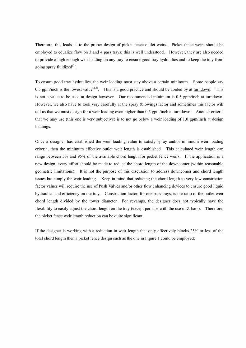
If the designer is working with a reduction in weir length that only effectively blocks 25% or less of the
total chord length then a picket fence design such as the one in Figure 1 could be employed:
Weir Height
Chord Length
Figure 1 – low blockage picket fence outlet weir
This arrangement has a high open area for liquid to flow through and for the up-flowing vapor to "expand"
over the downcomer. Current vapor capacity correlations take advantage of this area/volume over the
downcomer as a place for the vapor to expand and help "drop" the liquid it carries upward. Having as
much as a 25% blockage above the weir does not inhibit this expansion of vapor and limit vapor capacity
on the tray. Please note that the opening/blockages are spread uniformly over the full length of the chord.
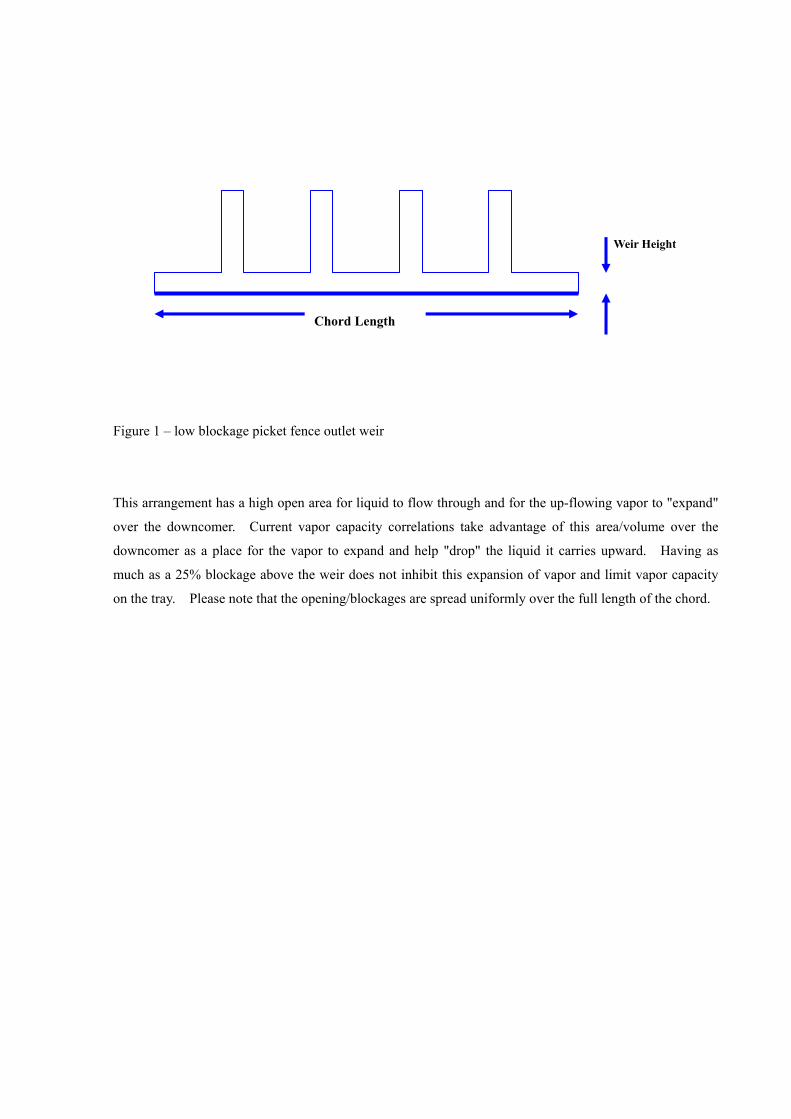
For the range of 25% to 50% blockage, the picket fence weir will look more like that shown in Figure 2:
Weir Height
Chord Length
Figure 2 – medium blockage picket fence outlet weir
For this situation there is a certain amount of blockage that will inhibit a portion of the vapor expansion
over the downcomer. The designer should examine the vapor capacity very carefully to see what the
difference is between the free area and the bubbling area and potentially decrease vapor capacity.
The capacity of a tray can be adjusted to account for this by the loss of free area over the downcomer. At
the present time this is not accounted for. Free area is simply defined as the bubbling area plus the area
over the downcomers (and is sometimes limited to 1.15 times the bubbling area). This limiting of the free
area can be accomplished by proportionalizing the additional area the calculated free area has in excess of
the bubbling area to the effective chord length divided by the true chord length at the outlet weir.
Basically in our tray design programs we would do the following:
1.) Calculated the excess area: Aex = AF -AA
2.) Proportion the excess area: Aex' = Aex(weir length/chord length)
3.) New Free Area would then be: AF = Aex' + AA
where,
Aex = Excess Area
AF = Free Area
AA = Bubbling Area (or Active Area)
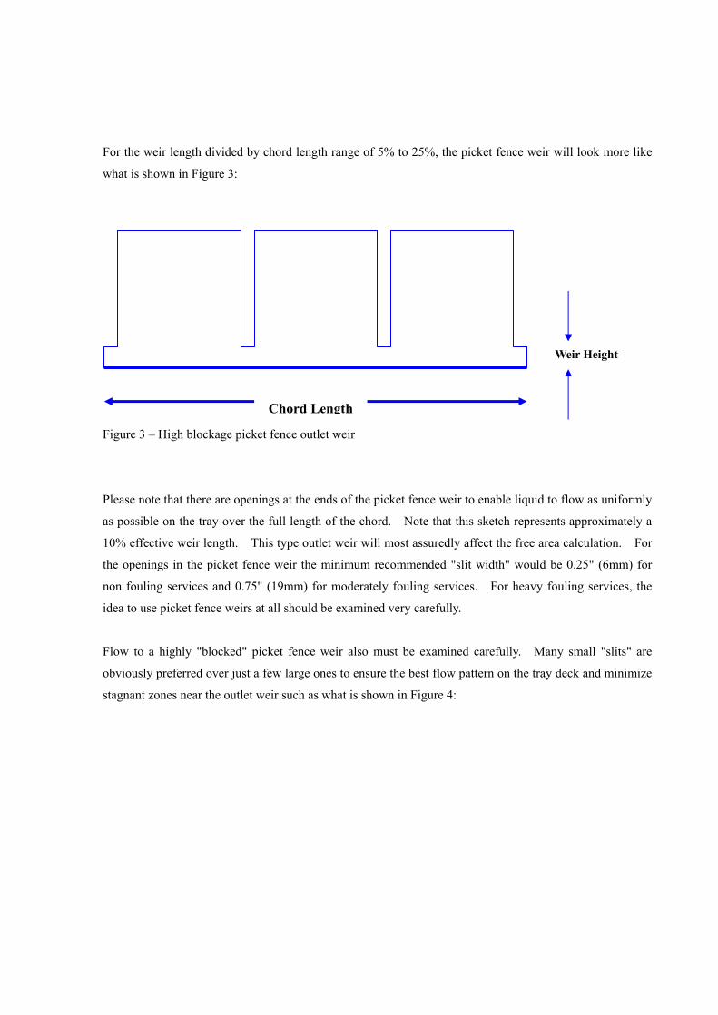
For the weir length divided by chord length range of 5% to 25%, the picket fence weir will look more like
what is shown in Figure 3:
Weir Height
Chord Length Figure 3 – High blockage picket fence outlet weir
Please note that there are openings at the ends of the picket fence weir to enable liquid to flow as uniformly
as possible on the tray over the full length of the chord. Note that this sketch represents approximately a
10% effective weir length. This type outlet weir will most assuredly affect the free area calculation. For
the openings in the picket fence weir the minimum recommended "slit width" would be 0.25" (6mm) for
non fouling services and 0.75" (19mm) for moderately fouling services. For heavy fouling services, the
idea to use picket fence weirs at all should be examined very carefully.
Flow to a highly "blocked" picket fence weir also must be examined carefully. Many small "slits" are
obviously preferred over just a few large ones to ensure the best flow pattern on the tray deck and minimize
stagnant zones near the outlet weir such as what is shown in Figure 4:
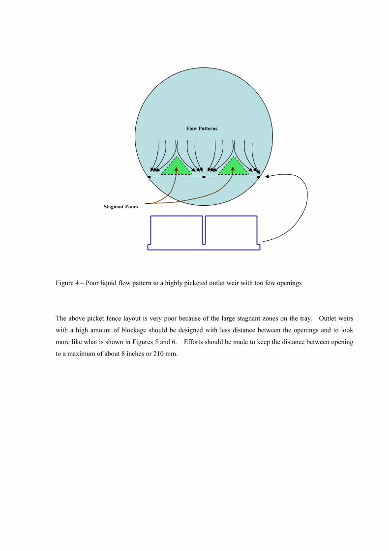
Flow Patterns
Stagnant Zones
Figure 4 – Poor liquid flow pattern to a highly picketed outlet weir with too few openings
The above picket fence layout is very poor because of the large stagnant zones on the tray. Outlet weirs
with a high amount of blockage should be designed with less distance between the openings and to look
more like what is shown in Figures 5 and 6. Efforts should be made to keep the distance between opening
to a maximum of about 8 inches or 210 mm.
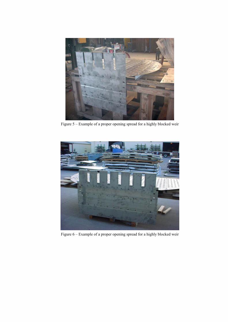
Figure 5 – Example of a proper opening spread for a highly blocked weir
Figure 6 – Example of a proper opening spread for a highly blocked weir
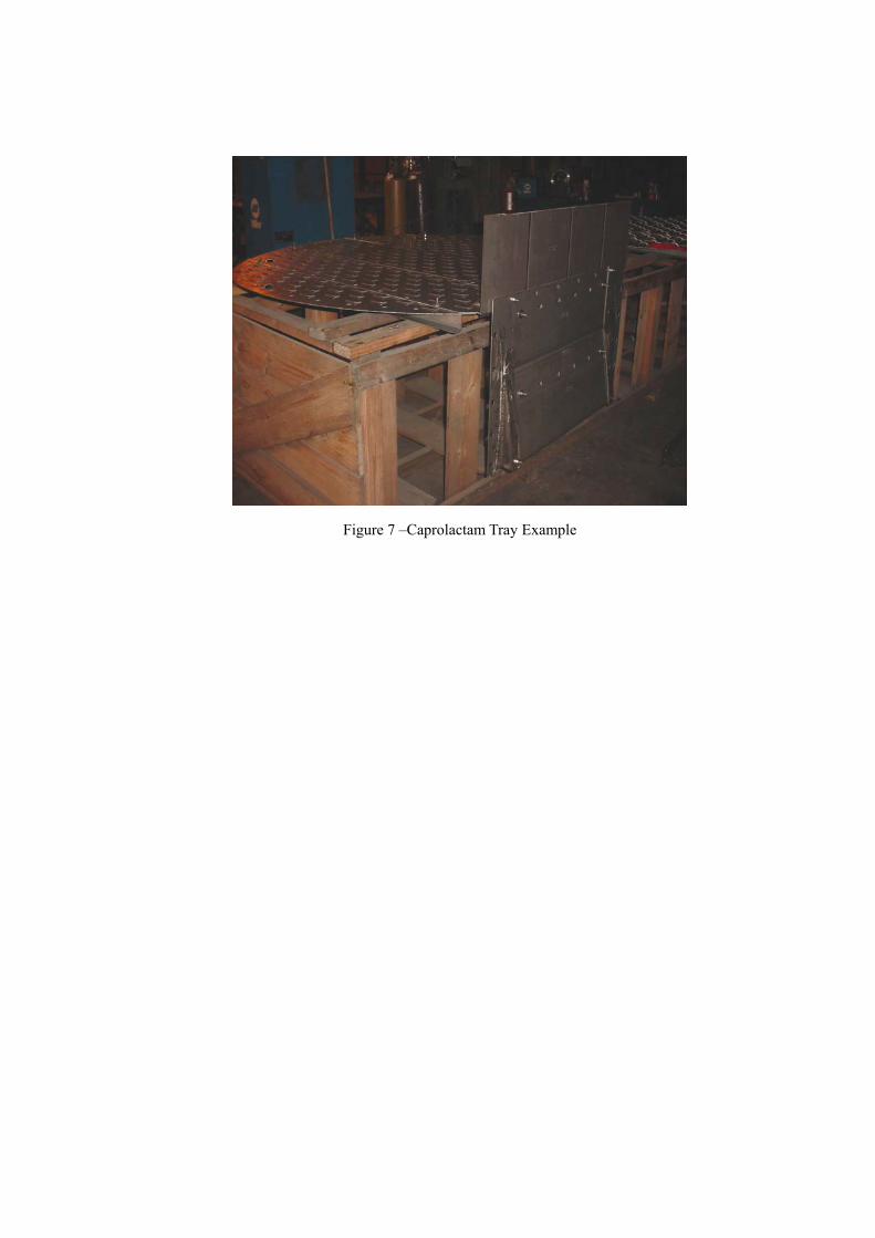
Figure 7 –Caprolactam Tray Example
Conclusions
Based on the above discussion, low liquid load applications can be handled with proper Picket Fence design
techniques. These techniques include:
1. Adjustments to capacity
2. Good Picket Weir Design Practices
3. Proper choice of minimum allowable weir loadings
4. Attention must be paid to the Spray Factor
5. Proper placement of outlet weir openings
6. Minimization of stagnant zones on highly picketed weirs
Blockages to the outlet weir length of 80 to 95% are not unusual and have been used frequently in the
industry to ensure good tray performance at low liquid loads.
References
1. H. Z. Kister, “Distillation Operation”, 1990, pp 162-163
2. M. J. Lockett, “Distillation tray fundamentals”, 1986, p 103
3. A. W. Sloley, “Improve Tray Operations”, Hydrocarbon Processing, June 2001, pp 85-86
4. C. J. Colwell, “Clear Liquid Height and Froth Density on Sieve Trays”, Ind. Eng. Process
Design and Development, 1981, Volume 20, pp 298-307
5. A. Sloley, "Improve Tray Operations", 2001, pp 85-86
6. M. J. Lockett, ”distillation tray fundamentals”, 1986, p 58
7. G.X. Chen, Z Fan, "Models for Liquid Head, Pressure Drop and Weeping of Sieve Trays",
October 15, 1995, FRI Topical Report 119
8. M. J. Lockett, ”distillation tray fundamentals”, 1986, p 35
9. M. Sakata and T. Yanagi, "Performance of a Commercial Scale Sieve Tray", I. Chem. E.
Symposium Series No. 56, 1979, pp 3.2/21-33
10. H. Z. Kister and J. R. Haas, "Entrainment from Sieve Trays in Froth Regime", Ind. Eng. Chem.
Res., 1988, pp 2331-2341
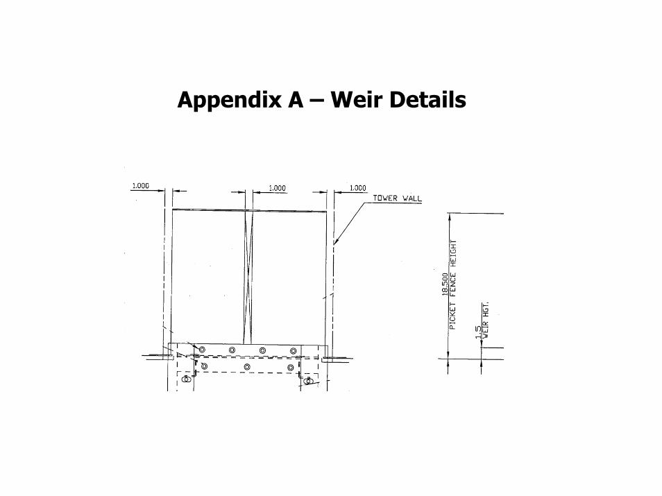
Appendix A – Weir Details
Appendix A Project: Service: Toluene Recovery Item: V-1005-INT Sulzer Chemtech Top pressure: Date Run: 27-Feb-2006 Downcomer Type: STANDARD Geometry: TRAYS Tray Dimensions: Deck Type: SVG Tray Spacing, [in]: 24 Tower Diameter,[in]: 35.25 Valve Lift, [in]: 0.5 Number of Passes: 1 No. of Valve Units: 56 Tray Thickness, [in]: 0.1345
Downcomer Dimensional Input Data: Tray Area Calculated Output: Side Center Off-Center Open Area, [ft2]: 0.66 Downcomer Top Width, [in]: 4 N/A N/A Open Area, [%]: 11.07 Downcomer Bottom Width, [in]: 4 N/A N/A Tower Area, [ft2]: 6.78 Downcomer Clearance, [in]: 0.75 N/A N/A Downcomer Area, [ft2]: 0.42 Outlet Weir Height, [in]: 1.5 N/A N/A Downcomer Area, %: 6.3 Outlet Weir Length per D.C.,[in]: 0 N/A N/A Active Area, [ft2]: 5.93 Inlet Weir Height, [in]: 0 N/A N/A Active Area, %: 87.5 Rec. Pan Depth, [in]: 0 N/A N/A Pan Width, [in]: 0 N/A N/A Radius Tip Downcomer: NO NO NO Downcomer Calculated Output: Downcomer Top Area, [ft2]: 0.42 0 0 Valve Density, [#/ft2]: 9.4 Downcomer Bottom Area, [ft2]: 0.42 0 0 Eff. Weir Length/Downcmr,[in]: 22.36 0 0 Fluid Data Input: Case Number: 1 2 Fluid Name: TRAY 6 TRAY 12 Description: TOP 1998 Trays 1998 Trays Vapor: Flow Multiplier: 1 1 Mult. Vapor Rate, [lb/hr]: 16103 17263 Density, [lb/ft3]: 0.234 0.237 QV, [CFS]: 19.12 20.23 Liquid: Flow Multiplier: 1 1 Mult. Liquid Rate, [lb/hr]: 2233 3383 Density, [lb/ft3]: 48.59 48.36 Surface Tension, [d/cm]: 17.65 17.44 Viscosity, [cP]: 0.249 0.233 QL, [gpm]: 5.73 8.72 System Factor : 1 1 Calculated Output:
Original Trays from 1998
Jet Flood, [%]: 54 58 Downcomer Velocity, [%]: 5 8 Downcomer Froth Backup, [%]: 16 18 Downcomer Clear Liquid, [in Liq]: 2.61 2.98 Weir Loading, [gpm/in]: 0.26 0.39 DryDrop, [in H20]: 1.27 1.44
Delta P, [mmHg]: 2.9 3.3
Design Notes:
Engineer Name: DRSummers File: C:\DRS\PAPERS\April 2006\C024774.STF Copyright © 2004. This information is the exclusive property of Sulzer Chemtech and It can not be distributed to any party without written consent from Sulzer Chemtech. The figures indicated herein are for information purposes only and not binding to the supplier. Any assured Page 1 of 4 quality performance guarantee or specification may only be accepted, if expressly identified as such. Printed: 27-Feb-2006 8:41:59 PM Build: 1.11.2005.
Appendix A Project: Service: Toluene Recovery Item: V-1005-INT Sulzer Chemtech Top pressure: Date Run: 27-Feb-2006 Geometry: TRAYS Summarized Calculated Output: Case Number: 1 2 Fluid Name: TRAY 6 TRAY 12 Vapor Flow Multiplier: 1 1 Mult. Vapor Rate, [lb/hr]: 16103 17263 Liquid Flow Multiplier: 1 1 Mult. Liquid Rate, [lb/hr]: 2233 3383 QV, [CFS]: 19.12 20.23 QL, [CFS]: 0.01 0.02 Vload, [CFS]: 1.33 1.42 GPM: 5.7 8.7 Cb, [ft/sec]: 0.224 0.24 Cf, [ft/sec]: 0.209 0.224 Weir Loading, [gpm/in]: 0.26 0.39 Crest over Weir, [in]: 0.16 0.21 Spray Regime Factor: 1.45 1.55 Sieve Vibration Factor: 7.85 7.36 Tray Froth Height, [in]: 4.39 5.01 HF/TS Ratio, [%]: 18.3 20.9 Tray Aeration Factor: 0.084 0.084 Hydrostatic Head, [in]: 0.37 0.42 Dry Tray Delta-P, [in H20]: 1.268 1.438 Vapor Head, [mmHg]: 0.165 0.167 Tray Pressure Drop, [in H20]: 1.56 1.77 Tray Pressure Drop, [mmHg]: 2.9 3.3 Tray Pressure Drop, [psi]: 0.06 0.06 Downcomer Velocity, [ft/sec]: 0.03 0.046 Downcomer Froth Backup, [in]: 4 4.6 Downcomer Froth Backup, [%]: 16 18 D.C. Clear Liquid, [in Liq]: 2.61 2.98 Downcomer Aeration Factor: 0.646 0.649 Downcomer Exit Froth Density: 1 1 Downcomer Head Loss, [in]: 0.01 0.01 D.C. Exit Velocity, [ft/sec]: 0.11 0.17 Max. Dncmr Res. Time, [sec]: 70.7 46.4 Deck Holdup, [lbs]: 8.9 10.1 Downcomer Holdup, [lbs]: 4.5 5.1 Tray Holdup, [lbs]: 13.4 15.2 Residence Time,[sec]: 21.6 16.2 Useful Capacity, [%]: 63.58 67.94 Jet Flood, [%]: 54 58 Limit Flood, [%]: 37.02 39.63
Design Notes:
Engineer Name: DRSummers File: C:\DRS\PAPERS\April 2006\C024774.STF Copyright © 2004. This information is the exclusive property of Sulzer Chemtech and It can not be distributed to any party without written consent from Sulzer Chemtech. The figures indicated herein are for information purposes only and not binding to the supplier. Any assured Page 2 of 4 quality performance guarantee or specification may only be accepted, if expressly identified as such. Printed: 27-Feb-2006 8:41:59 PM Build: 1.11.2005.
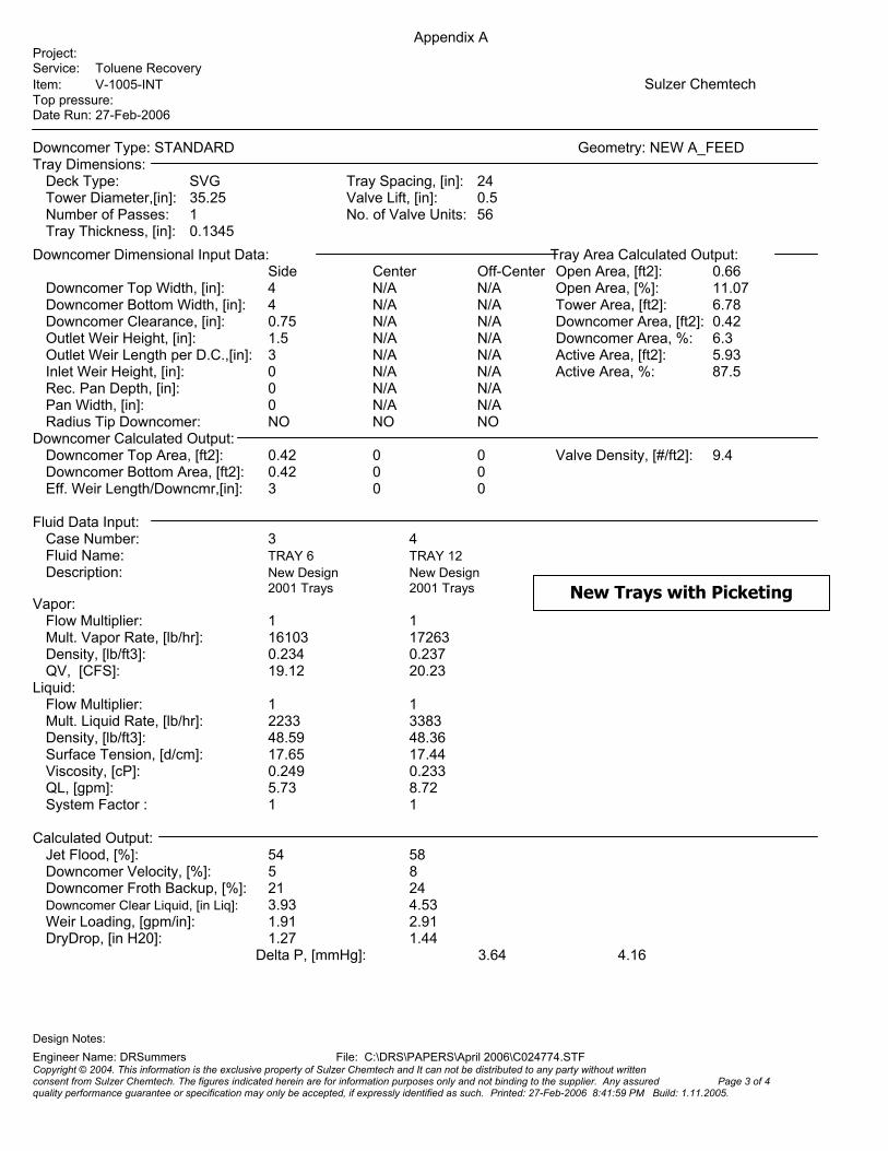
Appendix A Project: Service: Toluene Recovery Item: V-1005-INT Sulzer Chemtech Top pressure: Date Run: 27-Feb-2006 Downcomer Type: STANDARD Geometry: NEW A_FEED Tray Dimensions: Deck Type: SVG Tray Spacing, [in]: 24 Tower Diameter,[in]: 35.25 Valve Lift, [in]: 0.5 Number of Passes: 1 No. of Valve Units: 56 Tray Thickness, [in]: 0.1345
Downcomer Dimensional Input Data: Tray Area Calculated Output: Side Center Off-Center Open Area, [ft2]: 0.66 Downcomer Top Width, [in]: 4 N/A N/A Open Area, [%]: 11.07 Downcomer Bottom Width, [in]: 4 N/A N/A Tower Area, [ft2]: 6.78 Downcomer Clearance, [in]: 0.75 N/A N/A Downcomer Area, [ft2]: 0.42 Outlet Weir Height, [in]: 1.5 N/A N/A Downcomer Area, %: 6.3 Outlet Weir Length per D.C.,[in]: 3 N/A N/A Active Area, [ft2]: 5.93 Inlet Weir Height, [in]: 0 N/A N/A Active Area, %: 87.5 Rec. Pan Depth, [in]: 0 N/A N/A Pan Width, [in]: 0 N/A N/A Radius Tip Downcomer: NO NO NO Downcomer Calculated Output: Downcomer Top Area, [ft2]: 0.42 0 0 Valve Density, [#/ft2]: 9.4 Downcomer Bottom Area, [ft2]: 0.42 0 0 Eff. Weir Length/Downcmr,[in]: 3 0 0 Fluid Data Input: Case Number: 3 4 Fluid Name: TRAY 6 TRAY 12 Description: New Design New Design 2001 Trays 2001 Trays Vapor: Flow Multiplier: 1 1 Mult. Vapor Rate, [lb/hr]: 16103 17263 Density, [lb/ft3]: 0.234 0.237 QV, [CFS]: 19.12 20.23 Liquid: Flow Multiplier: 1 1 Mult. Liquid Rate, [lb/hr]: 2233 3383 Density, [lb/ft3]: 48.59 48.36 Surface Tension, [d/cm]: 17.65 17.44 Viscosity, [cP]: 0.249 0.233 QL, [gpm]: 5.73 8.72 System Factor : 1 1 Calculated Output:
New Trays with Picketing
Jet Flood, [%]: 54 58 Downcomer Velocity, [%]: 5 8 Downcomer Froth Backup, [%]: 21 24 Downcomer Clear Liquid, [in Liq]: 3.93 4.53 Weir Loading, [gpm/in]: 1.91 2.91 DryDrop, [in H20]: 1.27 1.44
Delta P, [mmHg]: 3.64 4.16
Design Notes:
Engineer Name: DRSummers File: C:\DRS\PAPERS\April 2006\C024774.STF Copyright © 2004. This information is the exclusive property of Sulzer Chemtech and It can not be distributed to any party without written consent from Sulzer Chemtech. The figures indicated herein are for information purposes only and not binding to the supplier. Any assured Page 3 of 4 quality performance guarantee or specification may only be accepted, if expressly identified as such. Printed: 27-Feb-2006 8:41:59 PM Build: 1.11.2005.
Appendix A Project: Service: Toluene Recovery Item: V-1005-INT Sulzer Chemtech Top pressure: Date Run: 27-Feb-2006 Geometry: NEW A_FEED Summarized Calculated Output: Case Number: 3 4 Fluid Name: TRAY 6 TRAY 12 Vapor Flow Multiplier: 1 1 Mult. Vapor Rate, [lb/hr]: 16103 17263 Liquid Flow Multiplier: 1 1 Mult. Liquid Rate, [lb/hr]: 2233 3383 QV, [CFS]: 19.12 20.23 QL, [CFS]: 0.01 0.02 Vload, [CFS]: 1.33 1.42 GPM: 5.7 8.7 Cb, [ft/sec]: 0.224 0.24 Cf, [ft/sec]: 0.209 0.224 Weir Loading, [gpm/in]: 1.91 2.91 Crest over Weir, [in]: 0.62 0.81 Spray Regime Factor: 3.43 3.74 Sieve Vibration Factor: 3.32 3.05 Tray Froth Height, [in]: 7.73 8.93 HF/TS Ratio, [%]: 32.2 37.2 Tray Aeration Factor: 0.113 0.114 Hydrostatic Head, [in]: 0.88 1.02 Dry Tray Delta-P, [in H20]: 1.268 1.438 Vapor Head, [mmHg]: 0.162 0.163 Tray Pressure Drop, [in H20]: 1.95 2.23 Tray Pressure Drop, [mmHg]: 3.64 4.16 Tray Pressure Drop, [psi]: 0.07 0.08 Downcomer Velocity, [ft/sec]: 0.03 0.046 Downcomer Froth Backup, [in]: 5.3 6.1 Downcomer Froth Backup, [%]: 21 24 D.C. Clear Liquid, [in Liq]: 3.93 4.53 Downcomer Aeration Factor: 0.739 0.744 Downcomer Exit Froth Density: 1 1 Downcomer Head Loss, [in]: 0.01 0.01 D.C. Exit Velocity, [ft/sec]: 0.11 0.17 Max. Dncmr Res. Time, [sec]: 70.7 46.4 Deck Holdup, [lbs]: 21 24.3 Downcomer Holdup, [lbs]: 6.7 7.8 Tray Holdup, [lbs]: 27.8 32.1 Residence Time,[sec]: 44.8 34.2 Useful Capacity, [%]: 63.58 68.79 Jet Flood, [%]: 54 58 Limit Flood, [%]: 37.02 39.63
Design Notes:
Engineer Name: DRSummers File: C:\DRS\PAPERS\April 2006\C024774.STF Copyright © 2004. This information is the exclusive property of Sulzer Chemtech and It can not be distributed to any party without written consent from Sulzer Chemtech. The figures indicated herein are for information purposes only and not binding to the supplier. Any assured Page 4 of 4 quality performance guarantee or specification may only be accepted, if expressly identified as such. Printed: 27-Feb-2006 8:41:59 PM Build: 1.11.2005.
Appendix B – Weir Details
Appendix B Project: Service: Pressure column Item: CL-5 Sulzer Chemtech Top pressure: Date Run: 27-Feb-2006 Downcomer Type: STANDARD Geometry: TRAY Tray Dimensions: Deck Type: BDH Tray Spacing, [in]: 24 Valve Thickness, [in]: 0.0747 Tower Diameter,[in]: 72 Valve Lift, [in]: 0.5 Number of Passes: 1 No. of Valve Units: 230 Tray Thickness, [in]: 0.13 No. of Push Valves: 6 Push Valve Lift [in]: 0.375
Downcomer Dimensional Input Data: Tray Area Calculated Output: Side Center Off-Center Open Area, [ft2]: 2.85 Downcomer Top Width, [in]: 7 N/A N/A Open Area, [%]: 10.95 Downcomer Bottom Width, [in]: 5 N/A N/A Tower Area, [ft2]: 28.27 Downcomer Clearance, [in]: 1 N/A N/A Downcomer Area, [ft2]: 1.41 Outlet Weir Height, [in]: 1.5 N/A N/A Downcomer Area, %: 5 Outlet Weir Length per D.C.,[in]: 2 N/A N/A Active Area, [ft2]: 26 Inlet Weir Height, [in]: 0 N/A N/A Active Area, %: 92 Rec. Pan Depth, [in]: 0 N/A N/A Pan Width, [in]: 0 N/A N/A Radius Tip Downcomer: YES NO NO Downcomer Calculated Output: Downcomer Top Area, [ft2]: 1.41 0 0 Valve Density, [#/ft2]: 8.8 Downcomer Bottom Area, [ft2]: 0.86 0 0 Eff. Weir Length/Downcmr,[in]: 2 0 0 Fluid Data Input: Case Number: 1 2 Fluid Name: FLUID1 FLUID2 Description: BDH 50% increase Normal 50% Cap increas Vapor: Flow Multiplier: 1 1 Mult. Vapor Rate, [lb/hr]: 15703 23283 Density, [lb/ft3]: 0.053 0.065 QV, [CFS]: 82.3 99.5 Liquid: Flow Multiplier: 1 1 Mult. Liquid Rate, [lb/hr]: 1018 1545 Density, [lb/ft3]: 59.3 59 Surface Tension, [d/cm]: 55.93 54.67 Viscosity, [cP]: 0.22 0.234 QL, [gpm]: 2.14 3.26 System Factor : 1 1 Calculated Output: Jet Flood, [%]: 23 30 Downcomer Velocity, [%]: 0 1 Downcomer Froth Backup, [%]: 15 17 Downcomer Clear Liquid, [in Liq]: 3.33 3.61 Weir Loading, [gpm/in]: 1.07 1.63 DryDrop, [in H20]: 0.83 1.02
Delta P, [mmHg]: 3.5 3.88
Design Notes:
Engineer Name: Petar Pribic File: C:\DRS\PAPERS\APRIL 2006\CL-5-BDH.STF Copyright © 2004. This information is the exclusive property of Sulzer Chemtech and It can not be distributed to any party without written consent from Sulzer Chemtech. The figures indicated herein are for information purposes only and not binding to the supplier. Any assured Page 1 of 2 quality performance guarantee or specification may only be accepted, if expressly identified as such. Printed: 27-Feb-2006 10:36:12 PM Build: 1.11.2005.
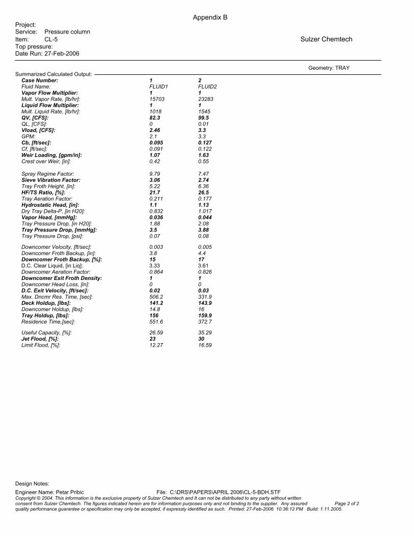
Appendix B Project: Service: Pressure column Item: CL-5 Sulzer Chemtech Top pressure: Date Run: 27-Feb-2006 Geometry: TRAY Summarized Calculated Output: Case Number: 1 2 Fluid Name: FLUID1 FLUID2 Vapor Flow Multiplier: 1 1 Mult. Vapor Rate, [lb/hr]: 15703 23283 Liquid Flow Multiplier: 1 1 Mult. Liquid Rate, [lb/hr]: 1018 1545 QV, [CFS]: 82.3 99.5 QL, [CFS]: 0 0.01 Vload, [CFS]: 2.46 3.3 GPM: 2.1 3.3 Cb, [ft/sec]: 0.095 0.127 Cf, [ft/sec]: 0.091 0.122 Weir Loading, [gpm/in]: 1.07 1.63 Crest over Weir, [in]: 0.42 0.55 Spray Regime Factor: 9.79 7.47 Sieve Vibration Factor: 3.06 2.74 Tray Froth Height, [in]: 5.22 6.36 HF/TS Ratio, [%]: 21.7 26.5 Tray Aeration Factor: 0.211 0.177 Hydrostatic Head, [in]: 1.1 1.13 Dry Tray Delta-P, [in H20]: 0.832 1.017 Vapor Head, [mmHg]: 0.036 0.044 Tray Pressure Drop, [in H20]: 1.88 2.08 Tray Pressure Drop, [mmHg]: 3.5 3.88 Tray Pressure Drop, [psi]: 0.07 0.08 Downcomer Velocity, [ft/sec]: 0.003 0.005 Downcomer Froth Backup, [in]: 3.8 4.4 Downcomer Froth Backup, [%]: 15 17 D.C. Clear Liquid, [in Liq]: 3.33 3.61 Downcomer Aeration Factor: 0.864 0.826 Downcomer Exit Froth Density: 1 1 Downcomer Head Loss, [in]: 0 0 D.C. Exit Velocity, [ft/sec]: 0.02 0.03 Max. Dncmr Res. Time, [sec]: 506.2 331.9 Deck Holdup, [lbs]: 141.2 143.9 Downcomer Holdup, [lbs]: 14.8 16 Tray Holdup, [lbs]: 156 159.9 Residence Time,[sec]: 551.6 372.7 Useful Capacity, [%]: 26.59 35.29 Jet Flood, [%]: 23 30 Limit Flood, [%]: 12.27 16.59
Design Notes:
Engineer Name: Petar Pribic File: C:\DRS\PAPERS\APRIL 2006\CL-5-BDH.STF Copyright © 2004. This information is the exclusive property of Sulzer Chemtech and It can not be distributed to any party without written consent from Sulzer Chemtech. The figures indicated herein are for information purposes only and not binding to the supplier. Any assured Page 2 of 2 quality performance guarantee or specification may only be accepted, if expressly identified as such. Printed: 27-Feb-2006 10:36:12 PM Build: 1.11.2005.
Appendix C Project: Service: Gasoline Fractionator Item: KT-10 Sulzer Chemtech Top pressure: Date Run: 19-Feb-2007 Downcomer Type: STANDARD Geometry: TRAYS 6-10 Tray Dimensions: Deck Type: SVG Tray Spacing, [mm]: 830 Tower Diameter,[mm]: 9500 Valve Lift, [mm]: 12.7 Number of Passes: 2 No. of Valve Units: 7188 Tray Thickness, [mm]: 4.55
Downcomer Dimensional Input Data: Tray Area Calculated Output: Side Center Off-Center Open Area, [m2]: 7.83 Downcomer Top Width, [mm]: 310 200 N/A Open Area, [%]: 11.99 Downcomer Bottom Width, [mm]: 310 200 N/A Tower Area, [m2]: 70.88 Downcomer Clearance, [mm]: 32 32 N/A Downcomer Area, [m2]: 1.9 Outlet Weir Height, [mm]: 32 32 N/A Downcomer Area, %: 2.7 Outlet Weir Length per D.C.,[mm]: 0 0 N/A Active Area, [m2]: 65.27 Inlet Weir Height, [mm]: 0 0 N/A Active Area, %: 92.1 Rec. Pan Depth, [mm]: 0 0 N/A Pan Width, [mm]: 0 0 N/A Radius Tip Downcomer: NO NO NO Downcomer Calculated Output: Downcomer Top Area, [m2]: 1.86 1.9 0 Valve Density, [#/m2]: 110.1 Downcomer Bottom Area, [m2]: 1.86 1.9 0 Eff. Weir Length/Downcmr,[mm]: 6510 18996 0 Fluid Data Input: Case Number: 1 Fluid Name: MAX 6-10 Description: Existing Trays Desired Max Vapor: Flow Multiplier: 1 Mult. Vapor Rate, [Kg/hr]: 838784 Density, [Kg/m3]: 1.277 QV, [m3/sec]: 182.46 Liquid: Flow Multiplier: 1 Mult. Liquid Rate, [Kg/hr]: 180458 Density, [Kg/m3]: 911.84 Surface Tension, [mN/m]: 25.29 Viscosity, [mPa-s]: 0.683 QL, [m3/hr]: 197.88 System Factor : 1 Calculated Output: Jet Flood, [%]: 71 Downcomer Velocity, [%]: 19 Downcomer Froth Backup, [%]: 27 Downcomer Clear Liquid, [mm Liq]: 123.8 Weir Loading, [m3/mh]: 15.2
Side Downcomers are ModArc Type with these Dimensions
DryDrop, [mm H20]: 78.59 Delta P,
Design Notes:
Engineer Name: DRSummers File: CCopyright © 2004. This information is the exclusive property of Sulzer Chemconsent from Sulzer Chemtech. The figures indicated herein are for informaquality performance guarantee or specification may only be accepted, if exp
310 mm
1145 mm
434 mm 434 mm
1852 mm
1924 mm
1924 mm
Diameter
310 mm
1145 mm
434 mm 434 mm
1852 mm
1924 mm
1924 mm
Diameter
[mbar]: 8.99
:\DRS\PAPERS\April 2006\03-0973 KT-10.STF tech and It can not be distributed to any party without written tion purposes only and not binding to the supplier. Any assured Page 1 of 4 ressly identified as such. Printed: 19-Feb-2007 10:35:17 AM Build: 1.11.2005.
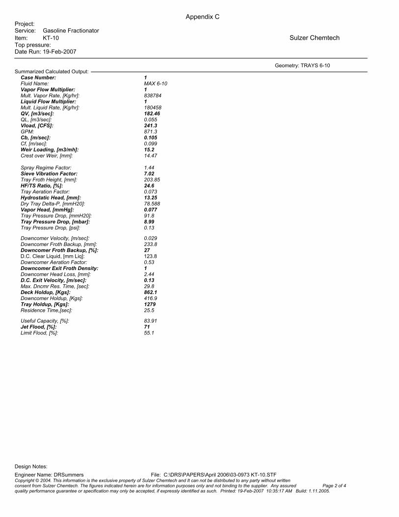
Appendix C Project: Service: Gasoline Fractionator Item: KT-10 Sulzer Chemtech Top pressure: Date Run: 19-Feb-2007 Geometry: TRAYS 6-10 Summarized Calculated Output: Case Number: 1 Fluid Name: MAX 6-10 Vapor Flow Multiplier: 1 Mult. Vapor Rate, [Kg/hr]: 838784 Liquid Flow Multiplier: 1 Mult. Liquid Rate, [Kg/hr]: 180458 QV, [m3/sec]: 182.46 QL, [m3/sec]: 0.055 Vload, [CFS]: 241.3 GPM: 871.3 Cb, [m/sec]: 0.105 Cf, [m/sec]: 0.099 Weir Loading, [m3/mh]: 15.2 Crest over Weir, [mm]: 14.47 Spray Regime Factor: 1.44 Sieve Vibration Factor: 7.02 Tray Froth Height, [mm]: 203.85 HF/TS Ratio, [%]: 24.6 Tray Aeration Factor: 0.073 Hydrostatic Head, [mm]: 13.25 Dry Tray Delta-P, [mmH20]: 78.588 Vapor Head, [mmHg]: 0.077 Tray Pressure Drop, [mmH20]: 91.8 Tray Pressure Drop, [mbar]: 8.99 Tray Pressure Drop, [psi]: 0.13 Downcomer Velocity, [m/sec]: 0.029 Downcomer Froth Backup, [mm]: 233.8 Downcomer Froth Backup, [%]: 27 D.C. Clear Liquid, [mm Liq]: 123.8 Downcomer Aeration Factor: 0.53 Downcomer Exit Froth Density: 1 Downcomer Head Loss, [mm]: 2.44 D.C. Exit Velocity, [m/sec]: 0.13 Max. Dncmr Res. Time, [sec]: 29.8 Deck Holdup, [Kgs]: 862.1 Downcomer Holdup, [Kgs]: 416.9 Tray Holdup, [Kgs]: 1279 Residence Time,[sec]: 25.5 Useful Capacity, [%]: 83.91 Jet Flood, [%]: 71 Limit Flood, [%]: 55.1
Design Notes:
Engineer Name: DRSummers File: C:\DRS\PAPERS\April 2006\03-0973 KT-10.STF Copyright © 2004. This information is the exclusive property of Sulzer Chemtech and It can not be distributed to any party without written consent from Sulzer Chemtech. The figures indicated herein are for information purposes only and not binding to the supplier. Any assured Page 2 of 4 quality performance guarantee or specification may only be accepted, if expressly identified as such. Printed: 19-Feb-2007 10:35:17 AM Build: 1.11.2005.
Appendix C Project: Service: Gasoline Fractionator Item: KT-10 Sulzer Chemtech Top pressure: Date Run: 19-Feb-2007 Downcomer Type: STANDARD Geometry: NEW 6-10 Tray Dimensions: Deck Type: SVG Tray Spacing, [mm]: 830 Tower Diameter,[mm]: 9500 Valve Lift, [mm]: 12.7 Number of Passes: 2 No. of Valve Units: 7188 Tray Thickness, [mm]: 4.55
Downcomer Dimensional Input Data: Tray Area Calculated Output: Side Center Off-Center Open Area, [m2]: 7.83 Downcomer Top Width, [mm]: 310 200 N/A Open Area, [%]: 11.99 Downcomer Bottom Width, [mm]: 310 200 N/A Tower Area, [m2]: 70.88 Downcomer Clearance, [mm]: 32 38 N/A Downcomer Area, [m2]: 1.9 Outlet Weir Height, [mm]: 90 90 N/A Downcomer Area, %: 2.7 Outlet Weir Length per D.C.,[mm]: 5500 11000 N/A Active Area, [m2]: 65.27 Inlet Weir Height, [mm]: 0 0 N/A Active Area, %: 92.1 Rec. Pan Depth, [mm]: 0 0 N/A Pan Width, [mm]: 0 0 N/A Radius Tip Downcomer: NO NO NO Downcomer Calculated Output: Downcomer Top Area, [m2]: 1.86 1.9 0 Valve Density, [#/m2]: 110.1 Downcomer Bottom Area, [m2]: 1.86 1.9 0 Eff. Weir Length/Downcmr,[mm]: 5500 11000 0 Fluid Data Input: Case Number: 2 Fluid Name: MAX 6-10 Description: New Pickets Desired Max Vapor: Flow Multiplier: 1 Mult. Vapor Rate, [Kg/hr]: 838784 Density, [Kg/m3]: 1.277 QV, [m3/sec]: 182.46 Liquid: Flow Multiplier: 1 Mult. Liquid Rate, [Kg/hr]: 180458 Density, [Kg/m3]: 911.84 Surface Tension, [mN/m]: 25.29 Viscosity, [mPa-s]: 0.683 QL, [m3/hr]: 197.88 System Factor : 1 Calculated Output: Jet Flood, [%]: 71 Downcomer Velocity, [%]: 19 Downcomer Froth Backup, [%]: 29 Downcomer Clear Liquid, [mm Liq]: 160.2 Weir Loading, [m3/mh]: 17.99 DryDrop, [mm H20]: 78.59
310 mm310 mm
Side Downcomers are ModArc Type with these Dimensions
Delta P,
Design Notes:
Engineer Name: DRSummers File: CCopyright © 2004. This information is the exclusive property of Sulzer Chemconsent from Sulzer Chemtech. The figures indicated herein are for informaquality performance guarantee or specification may only be accepted, if exp
1145 mm
434 mm 434 mm
1852 mm
1924 mm
1924 mm
Diameter
1145 mm
434 mm 434 mm
1852 mm
1924 mm
1924 mm
Diameter
[mbar]: 10.15
:\DRS\PAPERS\April 2006\03-0973 KT-10.STF tech and It can not be distributed to any party without written tion purposes only and not binding to the supplier. Any assured Page 3 of 4 ressly identified as such. Printed: 19-Feb-2007 10:35:17 AM Build: 1.11.2005.

Appendix C Project: Service: Gasoline Fractionator Item: KT-10 Sulzer Chemtech Top pressure: Date Run: 19-Feb-2007 Geometry: NEW 6-10 Summarized Calculated Output: Case Number: 2 Fluid Name: MAX 6-10 Vapor Flow Multiplier: 1 Mult. Vapor Rate, [Kg/hr]: 838784 Liquid Flow Multiplier: 1 Mult. Liquid Rate, [Kg/hr]: 180458 QV, [m3/sec]: 182.46 QL, [m3/sec]: 0.055 Vload, [CFS]: 241.3 GPM: 871.3 Cb, [m/sec]: 0.105 Cf, [m/sec]: 0.099 Weir Loading, [m3/mh]: 17.99 Crest over Weir, [mm]: 16.19 Spray Regime Factor: 2.99 Sieve Vibration Factor: 3.38 Tray Froth Height, [mm]: 293.41 HF/TS Ratio, [%]: 35.4 Tray Aeration Factor: 0.094 Hydrostatic Head, [mm]: 27.48 Dry Tray Delta-P, [mmH20]: 78.588 Vapor Head, [mmHg]: 0.076 Tray Pressure Drop, [mmH20]: 103.64 Tray Pressure Drop, [mbar]: 10.15 Tray Pressure Drop, [psi]: 0.15 Downcomer Velocity, [m/sec]: 0.029 Downcomer Froth Backup, [mm]: 267.2 Downcomer Froth Backup, [%]: 29 D.C. Clear Liquid, [mm Liq]: 160.2 Downcomer Aeration Factor: 0.6 Downcomer Exit Froth Density: 1 Downcomer Head Loss, [mm]: 2.44 D.C. Exit Velocity, [m/sec]: 0.13 Max. Dncmr Res. Time, [sec]: 31.8 Deck Holdup, [Kgs]: 1635.3 Downcomer Holdup, [Kgs]: 542.2 Tray Holdup, [Kgs]: 2177.4 Residence Time,[sec]: 43.4 Useful Capacity, [%]: 83.91 Jet Flood, [%]: 71 Limit Flood, [%]: 55.1
Design Notes:
Engineer Name: DRSummers File: C:\DRS\PAPERS\April 2006\03-0973 KT-10.STF Copyright © 2004. This information is the exclusive property of Sulzer Chemtech and It can not be distributed to any party without written consent from Sulzer Chemtech. The figures indicated herein are for information purposes only and not binding to the supplier. Any assured Page 4 of 4 quality performance guarantee or specification may only be accepted, if expressly identified as such. Printed: 19-Feb-2007 10:35:17 AM Build: 1.11.2005.