design of embedded and cyber-physical systems using a
TRANSCRIPT
Design of Embedded and Cyber-Physical SystemsUsing a Cross-Level Microarchitectural Pattern of theComputational Process OrganizationVasiliy Pinkevicha, Alexey Platunova and Yaroslav Gorbachevb
aITMO University, Kronverksky prospekt 49, Saint Petersburg, 197101, Russian FederationbLMT Ltd., Birzhevaya liniya 16, Saint Petersburg, 199034, Russian Federation
AbstractThe complexity and low efficiency of the reuse of various computational mechanisms and conceptualsolutions at the architectural and microarchitectural levels during the creation of embedded and cyber-physical systems is still an open problem. The paper proposes a microarchitectural pattern that allowsto represent the structure of the system being designed at various levels of abstraction and to guide thedesign process methodologically. The concept of the kernel, a special functional block, is introduced,which acts as the central reusable element of the pattern. The pattern organization the principles ofthe computational process representation in it are based on the aspect design model, the multi-levelrepresentation of the embedded system, and abstractions of the computing mechanism, platform, vir-tual machine. An example of the application of the proposed approach in some projects of distributedheterogeneous embedded systems is presented.
Keywordsembedded system, cyber-physical system, microarchitecture, SLD, design space exploration,aspect-based design, kernel
1. Introduction
The need for mass design and programming of microprocessor-based controllers is determinedby the further rapid digitalization of society. The era of cyber-physical systems (CPS) and theInternet of things presuppose deep automation of almost all areas of human life and activity[1]. The use of a limited number of standard solutions (info-communication design platforms)for a variety of different tasks, without being able to influence the internal, deep structure ofthese platforms, significantly limits the developer’s capabilities and degrades the quality of theproduct. However, existing custom low-level design and programming technologies for em-bedded systems (ES) and networked (distributed) embedded systems are still very troublesomeand time-consuming. The results of such design are poorly scalable and have a low reuse ratio[1, 2]. Moreover, a paradoxical situation arises when technologies for creating embedded andcyber-physical systems aimed at implementing one of the key propositions of the Industry 4.0
Proceedings of the 12th Majorov International Conference on Software Engineering and Computer Systems, December10–11, 2020, Online & Saint Petersburg, Russia" [email protected] (V. Pinkevich); [email protected] (A. Platunov); [email protected] (Y.Gorbachev)� 0000-0002-8635-5026 (V. Pinkevich); 0000-0003-3003-3949 (A. Platunov); 0000-0001-5419-6422 (Y. Gorbachev)
© 2020 Copyright for this paper by its authors.Use permitted under Creative Commons License Attribution 4.0 International (CC BY 4.0).
CEURWorkshopProceedings
http://ceur-ws.orgISSN 1613-0073 CEUR Workshop Proceedings (CEUR-WS.org)

initiative, namely, creating a fully automated production of customized goods “using a unifiedproduction line”, exclude automation systems themselves from the list of such custom systems.
One of the ways to solve the problem is to improve the technologies for creating complexembedded systems in the direction of developing methods and tools of the microarchitecturallevel in the end-to-end design route [3, 4]. In this case, the microarchitectural representation ofan embedded system or its part (for example, a controller) can be defined as the most importantmeta-level in the hierarchy of the design route abstractions [3, 5, 6, 7].
Here we use the term microarchitecture as the organization of a system or its component ata level below the level of the architectural description (the responsibility of the architect), butabove the level of the final implementation (software code, hardware schematics, etc.). In fact,these are the abstractions and principles of organization that the developer uses when creatingan implementation of the architecture defined in the specification.
This information in many projects (usually low-budget, although quite complex) remainspoorly documented (as good as comments in the source code). This leads to an excessivelylarge gap between the architectural specifications and the implementation. Because of this, theimplementation becomes non-transparent, and the system design is difficult to verify, maintain,and upgrade. As a result, it can become unmanageable.
Complex embedded systems projects in most cases, along with behavioral (functional) re-quirements, are characterized by many so-called non-functional requirements. It is useful todivide them into the final product requirements (for example, performance, reliability, energyefficiency) and requirements related to process/phases of the product life cycle, such as design,testing/certification, replication, maintenance, modernization, etc. The complex nature of ESdesign, which requires the developer to work with the requirements in a balanced manner, isstill poorly supported with industrial-level methods and tools. The above examples of non-functional requirements in hardware and software projects are most often implemented andcontrolled as a residual. The situation is even worse with the technologies and tools for CPScreating, since requirements from the application area related to the automation object areadded to the list of own ES design requirements [8, 9].
A large number of research groups are working to overcome these problems, the resultsof which are methodologies and tools related to the areas of “HW/SW Codesign” [10], ESLD[6, 11], aspect-based design [12, 13], languages for architectural design (architecture descriptionlanguages, ADL) [14], which are based on the advances in systems engineering [9, 15, 16].
This paper proposes a set of formalisms aimed at organizing and managing general andapplication-specific (including local) design routes with an emphasis on the project stages pre-ceding the implementation phase (architectural and microarchitectural design phases). For-malisms allow us to have a holistic view of the architecture of the product being created andits transformation while moving along the design route, as well as actively use and, if necessary,extract reusable design artifacts of various abstraction levels.
2. Problem statement
Existing reuse strategies during ES creation do not provide an opportunity to find an accept-able compromise between the design and development efforts and the quality of the product
being created. As a result, to obtain the optimal result from an engineering point of view, it isnecessary to develop the system essentially from scratch. On the other hand, if it is necessaryto reduce the development costs, a complete solution is used without the possibility of properadaptation to the project requirements. This happens because the traditionally used designplatforms are characterized by at least one of the following disadvantages:
• insufficient documentation of engineering solutions (only final implementation is avail-able);
• weak possibilities for configuring (adapting) the proposed engineering solutions to achievethe required characteristics;
• incomplete coverage of the stack of the necessary ES organization level (only the soft-ware level or only the level of the hardware platform);
• incomplete coverage of the necessary aspects (requirements) of the project.
For example, real-time operating systems (FreeRTOS, eCos, Embedded Linux) represent onlythe level of the system software, and often do not include components for implementing suchimportant service functions as in-system software updates. However, at the same time, theymay have ports for different families of microcontrollers and include rich standard driver li-braries.
The ready-made programmable logic controller (PLC) covers the full stack of levels fromhardware to user programming but is used as a “black box” without the possibility of anysignificant adaptation of its platform to the requirements of the project (adding new servicefunctions, optimization to reduce costs).
A family of microcontrollers with a library of standard drivers (for example, the STM32family and the STM32Cube tools) partially cover the ES hardware and system software layers,but the rest must be developed from scratch. Moreover, even the use of ready-made driverimplementations is often problematic due to their inflexibility and low level of optimization byperformance, memory consumption, etc.
We see the possibility of resolving the existing situation in the use of special design patternsas reusable objects, that cover the full set of organization levels [17, 18] and design aspects[19] for the target class of computing systems, as well as including several levels of descriptionof engineering solutions. We will call such objects microarchitectural design patterns. Thishighlights the critical importance of the microarchitectural level of the project documentationfor the project maintenance.
3. Aspect-based design
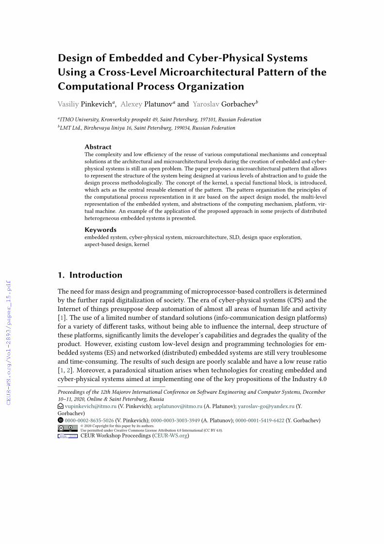
The complex nature of ES projects, combined with their growing complexity, requires the cre-ation of design methods and technologies that will effectively consider, analyze, synthesizeand track the quality of all recognized as essential parts of the ES organization and the infras-tructure existing around it throughout the life cycle, especially at the stages of creation andmodifications. Isolation of such relatively independent parts is a nontrivial process. We will

Figure 1: Steps of the aspect-based design process
refer to such localized parts of a project or target system as aspects. In other words, aspect issome particular design problem within the ES creation problem. Let us emphasize once againthat aspects do exist not within the framework of any stage or step in the development of aproject or target system, but they exist throughout the entire design process or the entire lifecycle of the system (the “weight” of an aspect in a project changes over time and can degen-erate to zero). The set that includes all aspects of the design will be called the aspect space ofthe ES design process. The set that directly belongs to the target system under creation will becalled the aspect space of the target system [19].
So, an aspect is an artificially allocated segment of the design space, reflecting a particularproblem of the project during its implementation (conceptual, local aspect). The designer him-self forms a list of aspects, which he then uses. The designer highlights the conceptual aspectsthat exist throughout the whole project duration and can highlight, if necessary, local aspectsat individual steps of the project (see Fig. 1) [19, 20].
Fig. 2 shows the result of transforming a traditional Y-diagram of a computing system intoan aspect diagram of an ES project:
• the center of the diagram, depending on the chosen interpretation of concentric circles,is the endpoint of the design process (implemented by ES) or the starting point (initialspecifications);
• concentric circles indicate the levels of the target system hierarchy or steps in the designprocess;
• axes correspond to the allocated (conceptual and local) aspects of the project;
• local aspects can cover a limited number of levels or project steps;
• points at the intersections of axes and circles are significant categories of objects or pro-cesses of the target system or ES project [21, 22].

Figure 2: Aspect diagram of a project
The design process for complex ES should involve a hierarchical representation of computa-tional platforms, functional description languages with their translators, and application-levelsolutions in a unified system of abstractions. This representation is aimed at project (func-tional and non-functional) aspects description, management, and maintenance in a uniformstyle, which makes it possible to increase the unification in the design of all ES components.The central idea is the consistent refinement/elaboration of the target system through the hi-erarchy of projects with a decreasing level of abstraction.
Fig. 3 illustrates an ES design process pattern based on the aspect model and composition ofcomputational platforms. Its advantages are:
• parallel balanced work with functional and non-functional requirements;
• generation of architecture from the basis of the proposed system of abstractions;
• combining the design and execution phases of the computational process within a singlespace of engineering solutions;
• a deferred phase of hardware-software partitioning.
4. Microarchitectural pattern
In any relatively complex computing system, the project designer can extract patterns thatallow some variation in implementation within the boundaries of this project. This is importantboth for the successful fulfillment of the requirements of the technical assignment and forimproving the quality of the project itself due to:
• providing a reserve of flexibility to fix bugs;
• the ability to easily adapt to new requirements arising during validation, integration,etc.;

Figure 3: ES design flow based on the aspect model and composition of computational platforms
• providing the potential for modernization;
• providing the possibility to reuse engineering solutions.
The microarchitectural pattern is designed to create complete systems of a certain class, soit is an object of a coarse granularity and has a fairly narrow scope of application. It is a patternfor both the target system and its design process.
The microarchitectural pattern differs from the framework, library, and platform in its coarsergranularity and self-sufficiency, as well as in the mandatory availability of information at thearchitectural and microarchitectural levels, although in a particular case it can be reduced tothem at the implementation level.
The microarchitectural pattern differs from design patterns both in its coarser granularityand specialization, and in its deeper implementation, and there may be several options forimplementing the pattern, both at the microarchitectural level and at the final implementationlevel.
Let us consider the complex microarchitectural pattern applied to the design of the dis-tributed automation systems controllers implemented on a microcontroller platform. Sucha platform includes one or more programmable microprocessors (including homo- and het-erogeneous multicore ones) with a set of coprocessors, input-output controllers, and memorydevices (both included in the microcontroller and external).
Since the microarchitectural pattern corresponds to a complete system, part of the patternis a subsystem focused on some particular task. Like the system as a whole, such a subsystemcannot be implemented using any standard library component, but is a specialized composition

of ready-made and original technical solutions. In the context of a microarchitectural pattern,we will call such a subsystem a kernel. The kernel is a specially allocated functional unit thathas the following properties:
• clearly defined functionality;
• several possible implementation variants at the software, hardware, or software-hardwarelevel;
• vectors of characteristics in various design aspects;
• the ability to scale by functionality and required resources;
• significant potential for reuse in a certain class of projects.
During the design process of distributed automation controllers, it is convenient to representas kernels the following elements:
• components responsible for input/output and networking;
• basic mechanisms for controlling the computational process (timers, interrupt system,scheduler, etc.);
• service functions (diagnostics, remote and in-system updating, configuration, informa-tion security, etc.);
• standard data processing functions (encryption algorithms, work with various data/fileformats, filtering, image processing, etc.);
• virtual machines, translators.
One of the most important properties of the kernel, in contrast to other functional blocks, isits focus for reuse. Firstly, its microarchitectural specification, and then its final implementa-tions. Kernel reuse is possible in the following ways (see Fig. 4a):
1. At the implementation level (source codes and hardware are reused).2. At the microarchitecture level (the way of computations organization and hardware/software
partitioning (if any) is reused).3. At the level of the functional interface (only the functionality and methods of interfacing
with components of the same level are reused).
Design and development of kernels require the biggest part of work when implementing aproject “from scratch”, but the requirements for them are usually weakly connected with theapplied problem being solved and are often not detailed in the system specification. They areprimarily responsible for organizing system and service processes. At the same time, the main(non-functional) applied characteristics and properties of the target system (cost, performance,power consumption, reliability, maintainability, etc.) depend on the quality of implementationof very these objects. In this regard, the set of kernels is the backbone for the controller project,and their design and implementation are the most critical parts of the project.

Figure 4: a) Levels of description and reuse of the kernel. b) An example of combining kernels withinsome organization level of the system
Since kernels can use lower-level kernels, their functionality and interface should be de-signed as versatile and flexible as possible, while keeping the overhead low. In this regard, theallocation of kernels may turn out to be nontrivial and not interfere with the usual functionalityof drivers in existing systems.
The vector of kernel characteristics is determined both by the its functions and by the variantof its implementation, including the characteristics of the lower-level kernels used.
The basis of the microarchitectural pattern is the integration of kernels in a single scalablestructure. Since each kernel can have several implementation options, the pattern is flexibleand adaptable to the requirements of a particular project (see Fig. 4b).
During the design process using a specific pattern, first of all, the required configurationand the necessary expansion of the pattern are defined. This provides conditions for the im-plementation of application functions with a given quality and the fulfillment of non-functionalrequirements. Then, on this basis, the main functionality of the system is developed.
From the target system design process point of view, the microarchitectural pattern solvesthe following tasks:
• specifies a set of requirements for the internal system organization (they are usuallyabsent in the initial specification);
• offers a set of engineering solutions for the target functions implementation;
• provides methodology on the use of engineering solutions;
• defines the segment of the design space in which the target system will be created;
• adjusts the design process by refining aspect weights and identifying local aspects.
Setting target characteristics for the pattern as a whole and each kernel imposes restric-tions on the choice of implementation options for each kernel in the pattern, including thepattern microarchitecture itself. Due to the many options for combinations of characteristics,

the choice of a particular option is a non-trivial task. Provided a kernel characteristics formal-ization exists, mathematical optimization methods are applicable (annealing method, geneticalgorithms, etc., used, i.e. in high-level synthesis tools [10, 23]).
Certain sets of requirements may not have appropriate implementation options within theexisting pattern and the pattern will need to be extended.
Depending on the degree of pattern kernels reuse, the following scenarios for using a patternin the design process are possible:
• direct use, only proper configuration is required;
• partial implementation changes (for example, because of a partial change in hardwarecomponents);
• partial redesign including developing new kernels and microarchitecture changes (forexample, if there are specific requirements or significant changes in hardware compo-nents).
A complete redesign of the pattern should only be required when the requirements or classof the system change radically.
Each new project that required a change in the microarchitectural pattern enriches it withnew engineering solutions. This expands the pattern and therefore increases its value as areusable artifact. To achieve this effect, all engineering solutions in the pattern must be prop-erly designed and documented, the necessary usage methodology must be provided. Thus, themethod of describing a pattern can be considered as a type of architectural style or architecturedescription language [24, 25], focused on displaying the relationships between key objects andgroups of reusable objects in the project.
Specification of a microarchitectural pattern consists of the following elements:
1. Kernels specifications:
• description of functionality, dependencies, characteristics;
• microarchitectural specifications of different implementation variants;
• reusable implementations (including the necessary configuration and automationtools).
2. Guidelines for:
• use of kernels and their integration;
• expansion of kernels with new variants of microarchitectural and target (low-level)implementation;
• development of new kernels.
5. Experiments and results
As an example of the application of the proposed approach, let us consider a pattern devel-oped and used at LMT Ltd. [26] to create controllers for various purposes. The pattern covers

Figure 5: Examples of kernels in the pattern
three levels of controller organization (hardware, system software, and application software) toprovide complete coverage of design tasks. The pattern uses: microcontrollers of the Coldfirefamily; a typical set of circuitry solutions and electronic component base; in-house system andapplication software platforms.
The pattern includes the following kernels:
• low-level input-output drivers (including UART, CAN, I2C, SPI, Ethernet);
• drivers for various protocols of controller networks and the Internet (including Modbus,CANPro, TCP/IP, in-house secure Internet protocol);
• drivers for supporting various memory chips and specialized devices (including DataFlash,GSM modems, radio transceivers);
• mechanisms of organizing parallel processes and interprocess communication;
• service mechanisms (diagnostics, in-system software update);
• a virtual machine of the user application programming language and the library of stan-dard functions.
Depending on their functions, kernels cover one to three levels of organization (see Fig. 5).Let us list and briefly describe some projects implemented using this pattern:1. A PLC for distributed automation systems SCG-4. The controller uses all three levels of
the organization presented in the pattern. A project-specific extension of the pattern is theexternal input/output and synchronization controllers implemented on the FPGA connectedto the microcontroller.
2. Network communicator of SCG-3.6 family for automated city lighting control system andautomated energy measurement system. The controllers do not use the user programminglayer because they have a fixed mission and do not imply changes in functionality by the enduser. They most widely use the set of communication channels and protocols supported by thepattern.
3. Controller of the scanning probe microscope MiniLab. The main mission of this con-troller is the implementation of high-performance digital signal processing to control measur-ing equipment. It is based on two patterns:

• controller of automation systems used as a control and communication core;
• FPGA-based digital signal processing processor with its own specific set of input-outputcontrollers.
The second pattern also implements a three-level organization of the computational processand has its own level of user application programming [27].
Due to the high level of engineering solutions unification within the pattern, all kernel im-plementations are reused in the listed and other projects, which significantly (up to 50-80 %)reduces efforts required for creating a new version of controller.
It is planned to port the pattern to a new family of microcontrollers, which will require tocreate new implementations of all kernels that directly interact with the functional blocks ofthe microcontroller. However, due to the reuse of functional interfaces and microarchitecturalspecifications, it will be possible to carry out practically seamless transfer of the applied func-tionality implementations and application-level user software.
Thus, the proposed approach to the allocation and structuring of reuseable objects in CPS andES projects based on microarchitectural patterns demonstrates high efficiency when creatingseveral systems of similar purpose and/or long-term maintenance of the single system.
In contrast to the existing solutions, the proposed approach involves the conscious formationand reuse of variable patterns at the level of the entire system, instead of developing similarsystems almost "from scratch" on the basis of fine-granularity reusable objects.
Fig. 6 shows an example of a microarchitectural description of the industrial automationcontroller project with focus of the infrastructure for remote data storing to the FLASH memoryarea of application programs. This subsystem is used when updating the user image of thesoftware and recording settings (only the part of the process that is directly responsible fordata transfer is displayed).
The figure contains elements of the computational process connected by arrows that showa logical end-to-end sequence of actions (but do not display secondary transitions, loops, andother feedbacks). The boxes below the description of the actions show the microarchitecturalelements and mechanisms used at each stage (implemented both at the purely software andhardware levels, and with a mixed implementation).
6. Conclusion
Improving the design efficiency of embedded and cyber-physical systems is a very complexand time-consuming task, which today is solved with low-level patterns, prototypes, and theimplementation-level reusable elements. This narrows the search space for design solutions,complicates scalability, and reduces the effectiveness of verification, debugging and testingtools. At the same time, “direct” attempts to implement complex projects at an abstract level,followed by hardware-software partitioning, are “stalling”.
We propose a compromise option that increases the abstraction degree of reusable (docu-mentable) solutions, methodologically “pushing” developers to this design style.
The question of choosing/creating a convenient and effective expressive means for this kindof abstractions with access to the automatic generation of an implementation-level spectrum

Figure 6: Example of a microarchitectural description: infrastructure for remote data storing to thecontroller’s FLASHmemory. A - microarchitectural elements of the external infrastructure, B - microar-chitectural elements of the controller.
of solutions remains open.
References
[1] M. Masin et al., “Cross-layer design of reconfigurable cyber-physical systems,” Design, Au-tomation & Test in Europe Conference & Exhibition (DATE), 2017, Lausanne, 2017, pp.740-745, doi: 10.23919/DATE.2017.7927088.
[2] M. Khalil, “Improving Solution Reuse in Automotive Embedded Applications using a Pat-tern Library Based Approach,” 2019 ACM/IEEE 22nd International Conference on ModelDriven Engineering Languages and Systems Companion (MODELS-C), Munich, Germany,2019, pp. 653-659, doi: 10.1109/MODELS-C.2019.00100.
[3] D. Densmore, R. Passerone, A. Sangiovanni-Vincentelli, “A Platform-Based Taxonomy forESL Design”, IEEE Design and Test of Computers, September 2006.
[4] Edward A. Lee. 2018. Modeling in engineering and science. Commun. ACM 62, 1 (January2019), 35–36. DOI: https://doi.org/10.1145/3231590

[5] Sangiovanni-Vincentelli A., Damm W., Passerone R. Taming Dr. Frankenstein: Contract-Based Design for Cyber-Physical Systems. Eur. J. Control. 2012. Vol. 18. P. 217—238.
[6] B. Bailey, G. Martin, “ESL models and their application”, New York: Springer Publication,2010.
[7] 7. Panagopoulos, G. Papakonstantinou, N. Alexandridis, and T. El-Ghazawi, “A compara-tive evaluation of models and specification languages for Embedded System design”, Lan-guages, Compilers, and Tools for Embedded Systems (LCTES-03), San Diego, Ca., June11-13, 2003.
[8] D. Broman, Ed. A. Lee, S. Tripakis, and M. Toerngren, “Viewpoints, formalisms, languages,and tools for cyber-physical systems”, 6th International Workshop on Multi-ParadigmModeling - MPM’12, October 2012, pp.49–54.
[9] S. Bonnet, F. Lestideau, J.-L. Voirin. Arcadia and Capella on the Field: Real-World MBSEUse Cases. MBSE Symposium, Canberra, October 27th, 2014.
[10] 10. J. Teich, “Hardware/software codesign: the past, the present, and predicting the fu-ture”, Proceedings of the IEEE, 2012, vol. 100, pp.1411 – 1430.
[11] A. Sangiovanni-Vincentelli, “Quo vadis SLD: reasoning about trends and challenges ofsystem-level design”, Proceedings of the IEEE, 95(3), 2007, pp.467-506.
[12] J. M. P. Cardoso, P. C. Diniz, J. G. de F. Coutinho, and Z. M. Petrov, “Compilation andSynthesis for Embedded Reconfigurable Systems: An Aspect-Oriented Approach (GoogleeBook)”, Springer, 2013, p. 215.
[13] A. Platunov, and A. Nickolaenkov, “Aspects in the design of software-intensive systems”,2012 Mediterranean Conference on Embedded Computing (MECO), June 2012, pp.84-87.
[14] P. H. Feiler, D. P. Gluch, and J. J. Hudak, The Architecture Analysis & Design Language(AADL): An Introduction. Software Engineering Institute, 2006.
[15] “ISO/IEC/IEEE 42010 Systems and software engineering — Architecture description.”2011.
[16] Essence – Kernel and Language for Software Engineering Methods. Foundation for theAgile Creation and Enactment of Software Engineering Methods (FACESEM) RFP, 2012.
[17] Kluchev A., Platunov A., Penskoi A. HLD methodology in embedded systems design witha multilevel reconfiguration. Proceedings - 2014 3rd Mediterranean Conference on Embed-ded Computing, MECO 2014 - Including ECyPS 2014, 2014, pp. 36-39
[18] Pinkevich V., Platunov A. Method for Testing and Debugging Flow Formal Specificationin Full-Stack Embedded Systems Designs. 9th Mediterranean Conference on EmbeddedComputing, MECO 2020 - Proceedings - 2020, pp. 9134213
[19] A. Platunov, A. Kluchev, and A. Penskoi, “HLD Methodology: The Role of ArchitecturalAbstractions in Embedded Systems Design”, 14th GeoConference on Informatics, Geoin-formatics and Remote Sensing, 2014, pp. 209–218.
[20] Penskoi A., Platunov A., Andreev V. The Selection Problem and Evaluating Method forArchitectural Design Tools of Embedded Systems. 8th Mediterranean Conference on Em-bedded Computing, MECO 2019 - Proceedings, 2019, pp. 150-154
[21] A. Chattopadhyay, “Ingredients of adaptability: a survey of reconfigurable processors”,VLSI Design, 2013, vol. 2013, p.18.
[22] Pinkevich V., Platunov A. Using architectural abstractions in embedded system design.Proceedings of the 4th Mediterranean Conference on Embedded Computing (MECO 2015),

Works in Progress in Embedded Computing (CD ROM) - 2015, Vol. 1, No. 1, pp. 3-6[23] Platunov A. E., Yanalov R. I. Design of computing platform for cyber-physical systems.
Journal of Instrument Engineering. 2017. Vol. 60, N 10. P. 993—998 (in Russian).[24] Clements P.C. A survey of architecture description languages. Proc. 8th Int. Work. Softw.
Specif. Des. – 1996. – pp. 16–25.[25] Shaw M. Comparing architectural design styles. IEEE Softw. – 1995. – V. 12 – No. 6 – pp.
27–41.[26] LMT Ltd. URL: https://lmt.spb.ru (accessed 01.11.2020)[27] Pinkevich V.Y., Platunov A.E., Penskoi A.V. The Approach to Design of Problem-Oriented
Reconfigurable Hardware Computational Units. Wave Electronics and its Application inInformation and Telecommunication Systems (WECONF 2020) - 2020, pp. 9131512