design of extrusion forming tools - polydynamics, inc. 5 blown film.pdf · 2019-10-03 · blown...
TRANSCRIPT
141
J. Vlachopoulos, R. Castillo, N. Polychronopoulos and S. Tanifuji
5.1 Introduction to Blown Film Extrusion
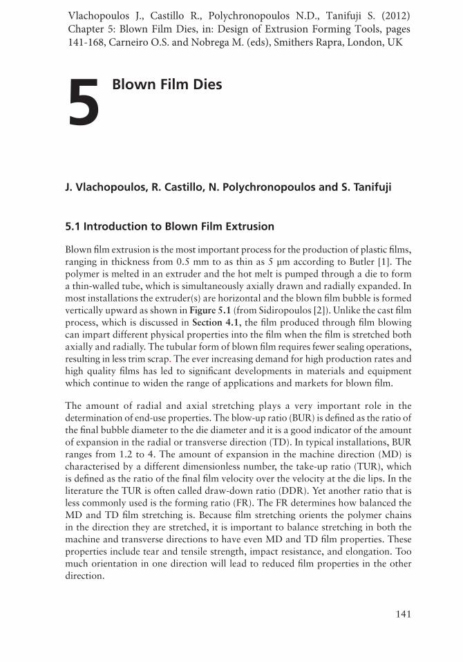
Blown film extrusion is the most important process for the production of plastic films, ranging in thickness from 0.5 mm to as thin as 5 μm according to Butler [1]. The polymer is melted in an extruder and the hot melt is pumped through a die to form a thin-walled tube, which is simultaneously axially drawn and radially expanded. In most installations the extruder(s) are horizontal and the blown film bubble is formed vertically upward as shown in Figure 5.1 (from Sidiropoulos [2]). Unlike the cast film process, which is discussed in Section 4.1, the film produced through film blowing can impart different physical properties into the film when the film is stretched both axially and radially. The tubular form of blown film requires fewer sealing operations, resulting in less trim scrap. The ever increasing demand for high production rates and high quality films has led to significant developments in materials and equipment which continue to widen the range of applications and markets for blown film.
The amount of radial and axial stretching plays a very important role in the determination of end-use properties. The blow-up ratio (BUR) is defined as the ratio of the final bubble diameter to the die diameter and it is a good indicator of the amount of expansion in the radial or transverse direction (TD). In typical installations, BUR ranges from 1.2 to 4. The amount of expansion in the machine direction (MD) is characterised by a different dimensionless number, the take-up ratio (TUR), which is defined as the ratio of the final film velocity over the velocity at the die lips. In the literature the TUR is often called draw-down ratio (DDR). Yet another ratio that is less commonly used is the forming ratio (FR). The FR determines how balanced the MD and TD film stretching is. Because film stretching orients the polymer chains in the direction they are stretched, it is important to balance stretching in both the machine and transverse directions to have even MD and TD film properties. These properties include tear and tensile strength, impact resistance, and elongation. Too much orientation in one direction will lead to reduced film properties in the other direction.
5 Blown Film Dies
Vlachopoulos J., Castillo R., Polychronopoulos N.D., Tanifuji S. (2012) Chapter 5: Blown Film Dies, in: Design of Extrusion Forming Tools, pages 141-168, Carneiro O.S. and Nobrega M. (eds), Smithers Rapra, London, UK
142
Design of Extrusion Forming Tools
Driven nip rolls
Guide rolls
Coolingair flow
Extruder Air ring
Spiral die
Air supply
Freeze line
Solidpolymerfilm
Layflat film
Figure 5.1 Schematic of the film blowing process. Adapted from V. Sidiropoulos, The Effects of Air Cooling on the Film Blowing Process, McMaster University,
Hamilton, ON, Canada, 2000. [Doctoral Thesis] [2]
Extruder sizes range usually from 25 to 200 mm in diameter with length over diameter (L/D) ratios from 20 to 34:1. Smooth barrel extruders are used in most installations, but some rigid materials with low coefficient of friction (e.g., high molecular weight high density polyethylene (HMW-HDPE)) require grooved barrel extruders. Furthermore, film blowing of HMW-HDPE (and some other linear, low melt flow index materials) typically leads to distinctive wine glass shaped or ‘high stalk’ bubbles, where a long and narrow neck extends from 5 to 9 die diameters above the die followed by a quick bubble expansion (BUR ranging from 3.5 to 5). Barrier screw designs have channels machined into their geometry which divide the molten from the solid polymer being processed through the extruder. The purpose of dividing the solid from the molten polymer is to increase melting and hence production rates. The goal
143
Blown Film Dies
of any feed screw design is to provide a stable rate of 100% molten homogeneous polymer to the die attached to the extruder. Die lip gaps usually range from 0.76 to 3 mm and the exiting melt stream is typically drawn down to film thicknesses ranging from 0.01 to 0.5 mm. Coextrusion of three to seven layers (sometimes up to 11) is often used for production of film for food packaging. The applications of coextruded films are highly diverse, and cover various industries from industrial to consumer ones.
The hot melt is cooled externally (and sometimes internally) by annular streams of high velocity air from film cooling devices called air rings. These air rings are situated close to the die lips outside and inside the film bubble and cooling air is blown onto the film as it is being extruded from the die. The cooling air helps to cool the hot melt as it exits the die and stabilises the shape of the molten tubular film. One of the goals of blown film extrusion is to cool the film being produced so that it solidifies at the highest possible rate. The maximum achievable output rate of the production line is often limited by the air cooling capability of the air rings. Specific output rate is a means to determine and compare the production rate of a die irrespective of the die diameter. The specific output rate is determined by dividing the output rate of the die in units of kg/h by the diameter of the die lips in mm. The die specific output rate for lines equipped with dual lip air rings, which cool the bubble from the outside, varies from 0.45 to 1.1 kg/h/mm of die diameter according to Butler [1]. Internal bubble cooling (IBC) increases the cooling capacity of the line by providing cooling from the inside of the bubble. The increased cooling capacity generally produces throughput rates from 0.7 to 2.0 kg/h/ mm of die diameter.
The main function of the die is to distribute the polymer melt evenly so that the thickness measured around the circumference of the tube being produced is uniform. Due to variations in distribution in the die and uneven cooling after the melt exits the die lips, there is always some film thickness nonuniformity. It is virtually impossible to eliminate film thickness variation, but systems have been developed to reduce it through flow modulation of the melt or the cooling air. If the film thickness variation is left unaddressed, when the film is wound up into a roll, thickness nonuniformity will be evident because the thicker or thinner spots (gauge bands) in the film will cause the roll to be of an uneven diameter. A way to address uneven diameter film rolls is to randomise the bands so that when the film is wound into a roll, the thick spots are spread across the width of the roll. Gauge band randomisation (i.e., the distribution of thicker and thinnner bands) can be accomplished by employing various techniques involving rotation or oscillation of the film bubble as it is being produced, by rotating/oscillating the apparatus that collapses the bubble and the nip rolls that pull the film upwards. It is possible that some gauge variation may be caused by the collapsing process itself because the distances from the points where the bubble first touches the collapser to the nip line are not all the same around the bubble circumference, as the cylindrical bubble is flattened.
144
Design of Extrusion Forming Tools
Polymers that are typically used in blown film are low density polyethylene (LDPE), linear low density polyethylene (LLDPE), HDPE and metallocene polyethylene (mPE), although several other polymers are sometimes used including ethylene copolymers, propylene copolymers, polyvinyl chloride, nylon and polypropylene homopolymer [3]. LDPE was produced using a high pressure reactor, and was one of the first polymers to be used for commercial film blowing. By the 1970s LLDPE had been developed and experienced widespread commercial acceptance in blown film extrusions. LLDPE was produced using the Ziegler-Natta catalyst process in a low pressure reactor. LLDPE gave a big boost to the industry with its excellent drawability and varied end use properties and applications. However, compared to LDPE, LLDPE has weaker melt strength and is prone to bubble instability. To address this issue, blends of LDPE/LLDPE, usually at a ratio of 70/30, are frequently used to combine the best of both polymers (the melt strength of LDPE and the drawability of LLDPE). More recently, in the 1990s, the development of metallocenes (mPE) has led to a completely new generation of polyolefin grades with excellent end use properties. Metallocene polyethylenes mPE generally have narrower molecular weight distributions and are less shear thinning than Ziegler-Natta polymers. Some grades have also been developed that include long chain branching, and these are more shear thinning. Metallocene polymers have lower melting and crystallisation points and they are sometimes more difficult to process into blown film than conventional polymers. Inevitably, a lot of tweaking of the equipment is required for successful blown film extrusion of the numerous commercially available polymer grades and their blends.
In film blowing, the final product has to meet specific performance requirements, which are usually set by the customer and often dictated by its end use. In that respect, the appropriate selection of the polymer, manufacturing equipment and process conditions is paramount for achieving the desired film properties and market requirements. Film properties are influenced by a plethora of parameters [4]. The type of monomer and comonomer, molecular weight and molecular weight distribution, chain branching, crystallinity and other parameters influence the behavior of the polymeric material, making it more suitable for some applications and less suitable for others. The common practice of blending different polymers further increases the range of possible properties. On the other hand, and in spite of the various polymer property options that exist, processing equipment (such as extruders, screws, dies, air rings and IBC) should be able to handle various different polymers thereby enabling processors to manufacture the film within the required tolerances, whilst meeting, and sometimes exceeding, production requirements. The effects of the polymer and manufacturing equipment on the film properties are unquestionable. However, modifications in those areas are often difficult and expensive in existing installations. Most manufacturers prefer to fine-tune the film properties by selecting their process parameters wisely. Extrusion temperature, screw speed, BUR, DDR, cooling intensity, freeze-line height, etc., can be easily adjusted and often result in significant changes in

145
Blown Film Dies
the film morphology. The final film properties are dictated by the molecular orientation (frozen-in stresses) and the crystalline structure of the film, which are the result of all the aforementioned parameters [4, 5].
5.2 Flow Distribution Considerations
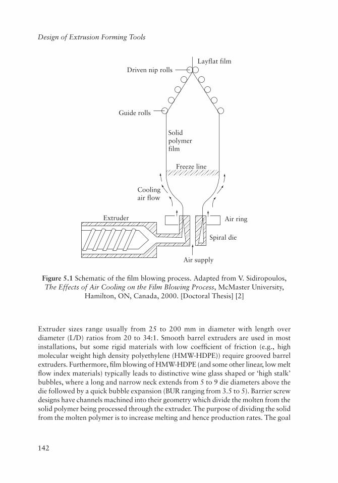
The purpose of an extrusion die is to impart the desired shape to the polymer melt stream produced continuously by the extruder. In blown film extrusion a thin tubular film is formed as the melt flows through the die lips. The die lip gap usually ranges from 0.76 mm to 3 mm and the die diameter from a few centimetres for laboratory lines to more than one metre for industrial installations producing more than one ton of film per hour. Production rates can easily exceed 1kg/h/mm of diameter for LDPE while for LLDPE it is usually less than 1kg/h/mm of diameter. The annular flow is formed in the gap between the inner mandrel and the outer die body. Several types of die have been proposed and built [6] as shown in Figure 5.2, involving mandrels supported by spider legs, screen packs or a breaker plate.
Mandrel support die
Mandrel
Mandrel support
Screen pack die
Screen pack
or Screen plate
Spiral mandrel die
Spiral mandrel distributor
Spider legs
Side-fed die
Mandrel
Figure 5.2 Different types of dies used for blown film extrusion. Adapted from W. Michaeli, Extrusion Dies for Plastics and Rubber, 2nd Edition,
Hanser Publishers, Munich, Germany, 1992 [6]

146
Design of Extrusion Forming Tools
Sometimes, side-fed as opposed to bottom-fed dies are used. The problem with these designs is that they result in the formation of weld lines [7] in the machine direction. These are formed when two polymer streams merge together. Along these merging lines (or weld lines), the polymer is poorly bonded due to very low diffusion coefficients of the large polymer molecules within the highly viscous melt. By far the most common die geometry for blown film production is the spiral mandrel geometry shown schematically in Figure 5.3.
MANDREL BODY
Figure 5.3 Schematic of spiral die. The polymer melt flows from extruder through a melt pipe at the bottom into the runners which guide it to the ports from
where the spirals originate. Reproduced with permission from J. Perdikoulias, Analysis and Design of Annular Dies for Mono- and Multilayer Polymer Flows,
University of Waterloo, Waterloo, ON, Canada, 1997. [Doctoral Thesis]. ©1997, J. Perdikoulias [22]
The polymer is fed by a number of melt tubes ending with a port at the start of each spiral. The melt flows both along the spirals and in the gap between the mandrel and outer body of the die. The flow rate becomes progressively more uniform around the

147
Blown Film Dies
circumference towards the die exit. After the end of the spirals the melt may pass through a low shear relaxation chamber of the type shown in Figure 5.4, for the purpose of reducing the memory of its complex strain history.
Fromspirals
Wide chamberLong final land
Neck-in / Neck-out
Fromspirals
Fromspirals
Figure 5.4 Relaxation chamber designs
Typically, the number of spirals in a mandrel die should be enough to accomplish uniform distribution of the polymer melt before it exits the die. One generally accepted notion among die designers is that a mandrel die should have one spiral per 25 mm of die diameter. Traditionally, it was believed that the more spirals in a mandrel die, the better the distribution would be. This is not so, since the entire length of each spiral can (and should) be used to distribute the polymer melt. With this in mind, fewer spirals can be used to provide adequate distribution and result in a uniform film thickness distribution at the die exit. Each spiral is machined into the outer diameter of the mandrel and travels a certain distance around the mandrel. Typically, a spiral starts deep and becomes progressively shallower the further down its length. The area which separates the spiral channels is known as the land. The gap over the land formed by the outer body that encloses the mandrel is what determines how much polymer flows over the land and how much travels down the spiral. As the spiral becomes shallower, the gap above the land becomes greater, allowing more polymer to travel over the land as opposed to in the spiral channel. The length of the spiral is another variable that is up for discussion amongst die designers. The length of a spiral is determined by the number of ports it overlaps on the mandrel from start to finish.
148
Design of Extrusion Forming Tools
It is sometimes believed that a longer spiral, or a spiral with many overlaps, provides better distribution than a spiral with fewer overlaps. This, also, is not so since polymer distribution has a stronger dependence on the gap size between land and outer body. As noted before, if the entire length of the spiral is used for distribution, a shorter spiral that is properly designed will work better than a longer spiral whose length is not being used fully for distribution. Typically, a die with six to eight overlaps is acceptable for blown film die design. The spiral should be long enough for adequate distribution to take place.
One of the objectives of die design is to process materials whilst minimizing the residence time of the polymer in the die so as to reduce the possibility of degradation. Coextrusion dies are also frequently subjected to changes in materials and layer structures. This also requires the die to have a short residence time so that purge or change-over times are not excessive when switching from one polymer to another. Advances in blown film coextrusion die technology led to the development of flat spiral dies as will be explained in Section 5.5. Apart from ensuring smooth flow surfaces with no hang-up points, both cylindrical and flat spiral dies must have flow passages that are sized to provide adequate velocity and shear stress to keep the material moving along the flow surfaces. The width and depth of the spiral should be chosen to ensure that the polymer is moving with an adequate velocity, shear rate and shear stress. In simplest terms, reducing the residence time of a polymer melt in a die means increasing the velocity and hence increasing the system back pressure. The back pressure being produced is a function of die channel geometry and dimensions should be chosen so that the resulting back pressure is not a limiting factor in the production rate. A compromise exists between the relationship of residence time, output rate and back pressure.
As the molten polymer exits the die, the plastic tube being produced should ideally have a uniform thickness. When this molten tube is inflated (into a bubble) and stretched, any excessively uneven thicknesses tend to be exaggerated around the bubble circumference, resulting in film of an unacceptable quality. Mass flow variation and resultant thickness variations of more than 5% above the end of the spirals is usually unacceptable. In a poorly designed die, polymer melts tend to flow preferentially directly above the ports, resulting in periodic thick and thin patterns as shown schematically in Figure 5.5. Characteristically, the number of thick spots or peaks will correspond to the number of ports in the die. Long die lips and relaxation chambers are sometimes used to reduce the mass flow variation, but they also tend to increase the pressure drop resulting in a reduced production rate. This type of thickness distribution deficiency is a result of an incorrectly designed spiral die which is not distributing the molten polymer properly. The poor flow distribution is caused along the spirals and between mandrel and die body. Figure 5.6 shows schematically the flow rate in the spiral direction as a function of distance. Correspondingly, spiral leakage is the amount of material that flows out of the spiral. If a die has too much

149
Blown Film Dies
spiral leakage, a large portion of the spiral will remain unused for distribution purposes, resulting in a stagnant flow region which may cause polymer degradation and other production problems.
9753
% F
low
rat
e va
riat
ion
1-1-3-5-7-9
0° 180° 360°Position around the circumference
Thickness variation as a function of position
Figure 5.5 Schematic representation of circumferential thickness variation as a function of position for a four port die
Spir
al c
hann
el f
low
rate
Good
Bad
Very Bad
Distance
There must be flowin the spiral channel
to the very end
“Unwould” spiral channel
Figure 5.6 In a good spiral die design, polymer flow in the channel has to be maintained to the very end

150
Design of Extrusion Forming Tools
5.3 Mathematical Modelling
Proctor [8] was the first to develop a method for predicting the flow distribution through spiral mandrel dies. He made several simplifying assumptions by subdividing the flow field into simpler flow domains (elements) where the pressure and the flow rate can be calculated in a stepwise manner. Similar methodologies were subsequently developed by Helmy and Worth [9], Wortberg and Schmitz [10] and Vlcek and co-workers [11]. Rauwendaal [12] presented a simple model for calculating the pressure drop and other quantities in the spiral channels and the annular gap. Vlcek and co-workers [13] developed a control volume method and a software package allowing for flow in two dimensions in each control volume and incorporated temperature effects. A comprehensive study of spiral mandrel dies involving also a comparison of model predictions and experiments was carried out by Perdikoulias [14, 15]. Various other methodologies were presented by Saillard and Agassant [16], Fahy and Gilmour [17], Huang [18], Mavridis [19], Higuchi and co-workers [20, 21] and Perdikoulias [22].
Coyle and Perdikoulias [23] carried out fully three-dimensional (3D) finite simulations and concluded that the predicted major flow characteristics were similar to those of the two-dimensional control volume predictions. Sun and Gupta [24] examined the effect of elongational viscosity on the flow inside a spiral mandrel die using a 3D finite element software package. They concluded that the effect is small on velocity distribution, but large on predicted pressure and temperature distribution. Zatloukal and co-workers [25] carried out flow simulations in a flat spiral die. Michaeli and Blomer [26] presented a method for the design of flat spiral dies based on the flow network theory. Maleksadeh and co-workers [27] presented a flow analysis of flat spiral dies and a comparison with cylindrical spiral mandrel dies.
For simulation of polymer melt flow through the channels of a spiral die, the equations of conservation of mass, momentum and energy under creeping flow conditions (Reynolds number <<1) must be solved, with the assumption of incompressibity and without taking into account the variation of viscosity with pressure, as explained in Chapter 4 for flat die design.
Equation of conservation of mass:
0=⋅∇ V (5.1)
Equation of conservation of momentum:
(5.2)

151
Blown Film Dies
Equation of conservation of energy:
(5.3)
where V is the velocity vector, P pressure, stress tensor, ρ density, cp specific heat
capacity, T temperature, k thermal conductivity and the term V∇:τ represents the frictional heating (viscous dissipation). The stress tensor is usually expressed in terms of the generalized Newtonian fluid model (GNF) in the form:
(5.4)
where IID is the second (scalar) invariant of the strain rate tensor (given in Table 4.1):
(5.5)
The viscosity is usually expressed in terms of the power-law, Carreau-Yasuda and Cross models.
Power-law:
(5.6)
where K is the consistency index (i.e., the value of the viscosity at shear rate γ =1s-1) which is temperature dependent in the same way as zero shear viscosity. The power-law exponent is usually not a function of temperature.
Carreau-Yasuda:
(5.7)
152
Design of Extrusion Forming Tools
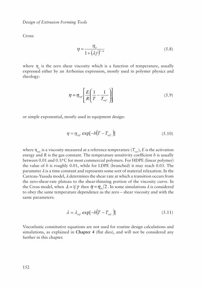
Cross:
(5.8)
where ηο is the zero shear viscosity which is a function of temperature, usually expressed either by an Arrhenius expression, mostly used in polymer physics and rheology:
−=
.
11ref
ref TTREηη (5.9)
or simple exponential, mostly used in equipment design:
(5.10)
where ηref. is a viscosity measured at a reference temperature (Tref.), E is the activation energy and R is the gas constant. The temperature sensitivity coefficient b is usually between 0.01 and 0.1/oC for most commercial polymers. For HDPE (linear polymer) the value of b is roughly 0.01, while for LDPE (branched) it may reach 0.03. The parameter λ is a time constant and represents some sort of material relaxation. In the Carreau-Yasuda model, λ determines the shear rate at which a transition occurs from the zero-shear-rate plateau to the shear-thinning portion of the viscosity curve. In the Cross model, when γλ 1= then 2οηη = . In some simulations λ is considered to obey the same temperature dependence as the zero – shear viscosity and with the same parameters:
(5.11)
Viscoelastic constitutive equations are not used for routine design calculations and simulations, as explained in Chapter 4 (flat dies), and will not be considered any further in this chapter.
153
Blown Film Dies
The momentum and continuity equations shown above can be easily simplified to the generalized Hele-Shaw approximation with the assumption of narrow gap geometry [28]. It applies to geometries in which the gap varies with position (provided there are not abrupt changes). Newtonian and the GNF models of power law, Carreau-Yasuda and Cross can easily be incorporated. For die design, if we assume that x is the direction of flow from the extruder end to the die lips, y is the lateral direction for layflat approximation of the cylindrical geometry and z perpendicular to the body surface, we can write the Hele-Shaw approximation as:
0=
∂∂
∂∂+
∂∂
∂∂
yPS
yxPS
x (5.12)
The quantity S(x,y) called the flow conductance, is defined as:
(5.13)
where h is the z direction gap.
The primary variable is the pressure, and after finding it the gapwise average velocity components are given by:
xP
hSVx ∂
∂−= y
PhSVy ∂
∂−= (5.14)
and the full velocity distributions can also be calculated, using:
(5.15)
where z΄ is a dummy variable of integration. The energy equation can be subsequently used to determine the temperature. This is a very useful approximation because it reduces significantly the complexity required to solve the fully 3D problem.

154
Design of Extrusion Forming Tools
5.4 Computer-assisted Spiral Die Design
If a suitable equation solver is available, the die designer must choose a spiral die geometry to perform a flow simulation for obtaining pressure drop, output mass flow rate (which corresponds to film thickness) variation, wall shear rate and wall shear stress, temperature distribution and other quantities which will be used for deciding whether a proposed design is satisfactory. The first die geometry choice is likely to be based on previous experience or knowledge of rules of thumb, such as those mentioned earlier in this chapter regarding the output rate per mm of diameter, the recommended number of spirals for the diameter chosen and the number of port overlaps for the channel. After a simulation for the first geometry is completed, the designer must examine the results to see how far the predictions are from the design constraints. Then the geometry must be updated and another simulation must be performed. This procedure must be continued until all the design constraints are satisfied. The usual constraints in spiral die design are the following:
(a) Pressure drop below a maximum value. Usually, single screw extruders can generate up to 50 MPa, but because of the pressure drop in melt pipes and other melt distributors, the actual pressure drop in the die would probably have to be less than the maximum in the extrusion line.
(b) The wall shear rate should not be less than a minimum value, which is frequently quoted as 8 s-¹, but for some temperature sensitive materials it should be higher. Low wall shear rate means that the fluid moves slowly over the wall and it may have time to degrade or the corresponding shear stress is low and the material will get stuck on the wall. While this low wall shear rate problem was identified many years ago and is well known amongst die manufacturers and polymer processors, the exact cause is not clear and there have not been any publications in the open literature providing an explanation supported by actual investigation of the local degradation and sticking phenomena. The region of the lowest shear rate is likely to be at the bottom wall of the spiral, and this is where the greatest attention must be focused.
(c) There should be flow all along the spiral so that the melt is continually renewed, with no possibility of stagnation. Towards the end of the spiral there might be a tendency for very slow or zero flow in the spiral direction, as shown schematically in Figure 5.6. Such situations should be avoided.
Other constraints might also be imposed, which may involve a maximum allowable wall shear stress at the die lips (to avoid sharkskin instability), a maximum residence time (to prevent degradation) and a maximum allowable temperature. The temperature of the melt increases beyond the set values on the die wall due to viscous dissipation (frictional heating) and the designer must examine the simulation results for potential
155
Blown Film Dies
hot spots, which should always be avoided. These constraints are similar to those for flat dies discussed in Chapter 4 but in this chapter, we deal with spiral dies which are more complicated than the flat dies discussed in Chapter 4.
A good software package can predict all of the above variables, enabling the designer to carry forward an iterative trial-and-error procedure on the computer screen until all the specifications of satisfactory performance are met. In this methodology, the search is for good or satisfactory solutions instead optimal ones. As Simon [29] put it, in his book on the philosophy of design, ‘no one will settle for good or better if he can have best. But that is not the way the problem usually poses itself in actual design situations. In the real world we usually do not have a choice between satisfactory and optimal solutions, for we only rarely have a method for finding the optimum’.
In spiral die design the number of variables is so large that it is impossible to find a globally optimum design. Some of the variables include: die diameter, die length, gap between the body and the mandrel, shape of gap (linear, parabolic or other), spiral channel depth, spiral channel angle of curvature, and form of the channel depth decrease from bottom to the top (linear, parabolic or other). Of course, it is possible to determine an optimum for a limited set of variables and constraints. The authors are not aware of any formal optimisation procedures which have had an impact on current spiral die technology, but this is an area which is likely to experience major developments in the not-too-distant future. In fact, a doctoral thesis has recently been published describing how an optimisation algorithm can be combined with numerical simulations for the automated design of spiral dies [30]. The present industrial practice, however, for spiral die design, is based on iterative simulation procedures which eventually lead to satisfactory design.
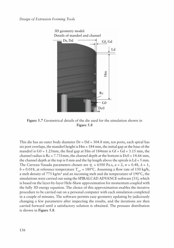
As an example, such a procedure was followed to arrive at the spiral mandrel die design shown in Figure 5.7.
156
Design of Extrusion Forming Tools
3D geometry model:Details of mandrel and channel
Dr, Dd Gf, Gd
Ld
Rc
G0
Dc0H
m
Figure 5.7 Geometrical details of the die used for the simulation shown in Figure 5.8
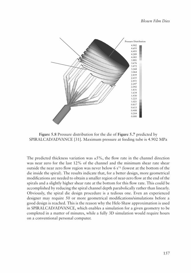
This die has an outer body diameter Dr = Dd = 304.8 mm, ten ports, each spiral has six port overlaps, the mandrel height is Hm = 184 mm, the initial gap at the base of the mandrel is G0 = 1.25mm, the final gap at Hm of 184mm is Gf = Gd = 3.15 mm, the channel radius is Rc = 7.731mm, the channel depth at the bottom is Dc0 = 14.66 mm, the channel depth at the top is 0 mm and the lip length above the spirals is Ld = 5 mm. The Carreau-Yasuda parameters chosen are η˳ = 6500 Pa.s, a = 2, n = 0.48, λ = 1, b = 0.018, at reference temperature Tref. = 180ºC. Assuming a flow rate of 150 kg/h, a melt density of 775 kg/m³ and an incoming melt and die temperature of 190ºC, the simulations were carried out using the SPIRALCAD ADVANCE software [31], which is based on the layer-by-layer Hele-Shaw approximation for momentum coupled with the fully 3D energy equation. The choice of this approximation enables the iterative procedure to be carried out on a personal computer with each simulation completed in a couple of minutes. The software permits easy geometry updating by judiciously changing a few parameters after inspecting the results, and the iterations are then carried forward until a satisfactory solution is obtained. The pressure distribution is shown in Figure 5.8.
157
Blown Film Dies
Pressure Distribution
4.9024.6934.4934.2894.0853.8813.6763.4723.2683.0642.8592.6552.4512.2472.0421.8311.6341.4301.2251.0210.8170.6130.4080.2040.000
Figure 5.8 Pressure distribution for the die of Figure 5.7 predicted by SPIRALCAD/ADVANCE [31]. Maximum pressure at feeding tube is 4.902 MPa
The predicted thickness variation was ±5%, the flow rate in the channel direction was near zero for the last 12% of the channel and the minimum shear rate shear outside the near zero flow region was never below 6 s‾¹ (lowest at the bottom of the die inside the spiral). The results indicate that, for a better design, more geometrical modifications are needed to obtain a smaller region of near-zero flow at the end of the spirals and a slightly higher shear rate at the bottom for this flow rate. This could be accomplished by reducing the spiral channel depth parabolically rather than linearly. Obviously, the spiral die design procedure is a tedious one. Even an experienced designer may require 50 or more geometrical modifications/simulations before a good design is reached. This is the reason why the Hele-Shaw approximation is used in SPIRALCAD/ADVANCE, which enables a simulation for a given geometry to be completed in a matter of minutes, while a fully 3D simulation would require hours on a conventional personal computer.

158
Design of Extrusion Forming Tools
5.5 Multilayer Blown Film Extrusion
A significant part of blown film being produced is coextruded, that is, it consists of two or more polymer layers. Nowadays, coextrusion of three to seven layers (sometimes up to 11) is typical. Food packaging films are almost exclusively multilayered because they are required to possess barrier and other physical properties. In barrier film coextrusion, the film structure has thin layers of the expensive barrier polymer, such as ethylene-vinyl alcohol, while layers of high strength polymers like polyamide provide the required mechanical properties. Also the skin layer polymer is carefully selected for optimum post-processing operations, such as printing and labeling. Thus, the final product can have all the desired properties at a significantly reduced cost [32].
Typically, spiral mandrel dies are the standard for producing coextruded blown film. In coextrusion spiral mandrel dies, the spirals are nested one inside the other (as shown in Figure 5.9 for a three-layer die) and are fed by different extruders.
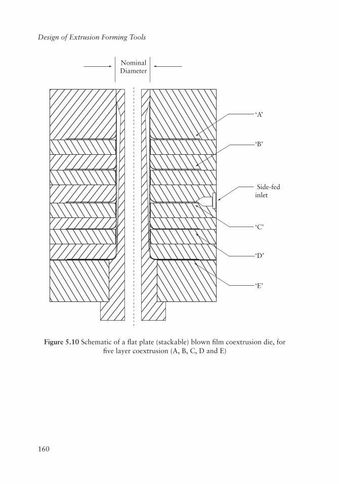
The resulting multilayer die is a complex structure, which is difficult to disassemble and maintain, and expensive to manufacture. The spiral die units of a multilayer die are not interchangeable and, therefore, there is limited flexibility to try different types of polymer for a given layer. These conventional blown film coextrusion dies distribute the polymer on the surface of concentric cylinders. Consecutive layers each have a correspondingly larger wetted surface area and larger residence times which may lead to polymer degradation. To address these limitations, recent technological developments have produced flat circular stackable plate spiral dies [33]. Adding more layers to a film structure offers a number of advantages. Firstly, increasing the number of layers allows a greater number of different polymers and polymer combinations to be used, resulting in an improved package. Secondly, a large number of coextruded layers gives a blown film line enhanced versatility, both in processing a variety of film structures and in meeting unknown future demands. Also, more layers give the user an improved ability to overcome specific processing problems. Increasing the number of layers also provides cost savings by allowing layers to be split and less expensive materials to be used in the structure. Contrary to the traditional spiral dies (where the spiral channels are cut in the surface of a cylinder), in flat plate stackable designs the spirals are cut on plates radially, and stacked one on top of another. A stack of such flat plates, as shown in Figure 5.10, can produce multilayer film structures, while being still easy to disassemble and maintain. The flat plates are interchangeable, so the types of polymers and the order of the layer structure are easily customised. Figure 5.11 shows how the spirals are laid on the surface of each plate. One of the other main differences between cylindrical and stackable dies is the omission of a bottom fed block in the latter. In the stackable die format the polymer melt is fed to the spirals from the side, directly connected to the extruder, as opposed to being bottom-fed in the cylindrical die design format. This format change has led to a die design that

159
Blown Film Dies
results in the entire melt flow passage from extruder adapter to the exit of the die being highly streamlined with no sharp bends to cause dead spots. Furthermore, all the layers have roughly the same wetted surface area because distribution takes place on the surface of the disc.
COMPUTER DESIGNEDLOW SHEAR SPIRALS
SEPERATE INNER AND OUTER LIP TEMPERATURE CONTROL
SYMMETRICAL COMBININGOF LAYERS
ADJUSTABLE OUTER LIP
DIE TOP INSULATED
SMOOTH ENTRY
STREAMLINE
TAPER LOCKLOCATION
Figure 5.9 Mechanical drawing of three layer coextrusion die. Reproduced with permission from Brampton Engineering, Brampton, ON, Canada
160
Design of Extrusion Forming Tools
NominalDiameter
‘A’
‘B’
‘C’
‘D’
‘E’
Side-fedinlet
Figure 5.10 Schematic of a flat plate (stackable) blown film coextrusion die, for five layer coextrusion (A, B, C, D and E)

161
Blown Film Dies
Streamlined passages Side fed entry for resin
Closed loop thermal fluid circulation system to maintain consistanttemperature of the module (heat or cool)
Figure 5.11 A side-fed flat spiral modular distribution. Reproduced with permission from Brampton Engineering, Brampton, ON, Canada
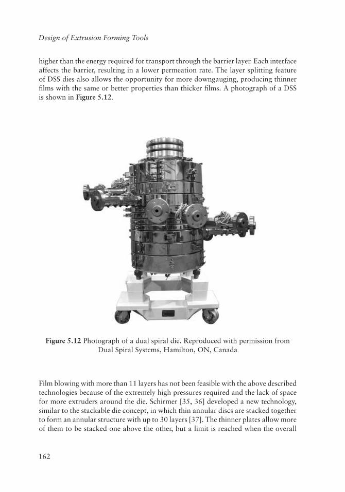
In a recent modification of the stackable die technology [34], spirals were introduced at both the top and the bottom of each plate, known as the Dual Spiral System (DSS). The DSS has, in every layer module, two identical spirals flowing in opposite directions on the two adjacent faces of the module, resulting in half the melt flow from the extruder going to one spiral and the other half to the other spiral. This layer splitting enables processors to take advantage of the improvements brought about from adding layers without additional equipment costs. By dividing each individual layer into two separate layers, the enhanced structural and physical properties of each layer material can be taken advantage of. This means that a five-module DSS blown film die would, in fact, be producing a ten-layer blown film product. Research has shown that layer division substantially reduces film thickness variation, increases output rates, strength, and the barrier properties of the film it is producing. As the number of layers increases, the number of interfaces between barrier layers also increases, resulting in a higher overall barrier properties of the layer split film. The barrier properties of a split barrier layer film will always be better than those of a coextruded film with a single barrier layer of the same material and same total thickness of barrier resin. The reason is that the energy required for oxygen penetration into the barrier layer is
162
Design of Extrusion Forming Tools
higher than the energy required for transport through the barrier layer. Each interface affects the barrier, resulting in a lower permeation rate. The layer splitting feature of DSS dies also allows the opportunity for more downgauging, producing thinner films with the same or better properties than thicker films. A photograph of a DSS is shown in Figure 5.12.
Figure 5.12 Photograph of a dual spiral die. Reproduced with permission from Dual Spiral Systems, Hamilton, ON, Canada
Film blowing with more than 11 layers has not been feasible with the above described technologies because of the extremely high pressures required and the lack of space for more extruders around the die. Schirmer [35, 36] developed a new technology, similar to the stackable die concept, in which thin annular discs are stacked together to form an annular structure with up to 30 layers [37]. The thinner plates allow more of them to be stacked one above the other, but a limit is reached when the overall

163
Blown Film Dies
pressure drop becomes too large. Dooley and co-workers [38, 39] developed a new concept based on the feedblock technology described in Chapter 4 in conjunction with a new type of cross-head die. Using a feedblock, over 100 microlayers are produced. These are then coated in another encapsulation feedblock and they are subsequently introduced into a cross-head die. In the cross-head die the feeding is from one side, as shown in the sketch at the bottom left of Figure 5.2. The polymer melt stream is split into two and the two flows join together on the opposite side, forming a weld line. To avoid discontinuity in the merging of microlayers at the expected location of the weld line, the ends of the two flow channels overlap. In the area of overlap, the film structure has equivalent barrier properties to the other areas according to Dooley and co-workers [38, 39]. There are no discernible optical differences between the overlap area and the main part of the blown film bubble.
One of the most common problems of coextruded blown film is the so-called zig-zag interfacial instability (also known as die land instability), where there are visible chevrons pointing in the flow direction. The mechanism responsible for this effect has not been conclusively identified (see also Chapter 4). It is speculated that interfacial instability is caused by amplification of certain disturbance wavelengths under high interfacial stress conditions (from 40 to 80 kPa). Viscoelasticity is probably a contributing factor, since the value of normal stresses is also important. Unfortunately, normal stresses are impossible to measure at high strain rates and very difficult to calculate. A commonly prescribed remedy to avoid zig-zag instability is viscosity matching, but it does not always work. Interfacial instability can occur even between layers of the same polymer. In fact, sometimes it is advisable to mismatch viscosities, for example, by putting a low viscosity skin layer in order to reduce interfacial shear. Other stress reducing actions that can be proven to be beneficial are: reducing the overall output rate, increasing the die gap and/or increasing the skin layer thickness (which places the interface further away from the wall).
5.6 Mechanical, Thermal, Gauge Control and Rheological Considerations
The flow of plastic inside an extrusion die during operation results in back pressure which, in turn, creates enough force on the die components so that deflection can occur on dies not designed to handle the pressure. This distortion can cause significant change to the gap geometry from the original design set point. Typical processing pressures can expand the body of a large die by over 1 mm in diameter. Obviously, this will seriously affect the performance of the distribution system. Care must be taken to ensure that the dimensions are accurate when the die is in production. If these effects are ignored, the film thickness distribution will be adversely affected and, in some cases,

164
Design of Extrusion Forming Tools
the melt flow may undesirably leak from the die. Finite element stress analysis of die components has become a useful tool in design. The behaviour of dies under thermal and mechanical loads can now be accurately predicted. For instance, deflections in the areas of critical die gaps will be known at the design stage, and thus can be compensated for in the design. The type of metal can also come into play as some steel alloys are better suited to die manufacturing than others. Some alloys are less prone to distorting, and are usually heat treated so as to maintain the structural integrity of the die.
The air cooling system is an integral part of any blown film line. It greatly affects not only the heat transfer from the molten polymer film, but also the stability and the shaping of the bubble. The bubble shape is primarily determined by mechanical manipulations and aerodynamics. Film cooling ultimately affects both the production rate and final film properties. External cooling is usually accomplished by dual orifice air rings [40-42] producing air jets which impinge on the outer bubble surface. IBC helps to increase the cooling of the film and results in significant increases in production rates up to perhaps 100%. The internal cooling is accomplished by stacks of radial air jets impinging on the inner side of the bubble [43]. The end-use properties of the film are also influenced by the bubble stabilisation, forming and bubble collapsing systems [44] and their interaction with air cooling. Troubleshooting of various instabilities, such as draw resonance, frost-line oscillation and bubble flutter [45], is of great importance in ensuring defect-free film products.
As explained earlier in this chapter, even with good die designs, some circumferential (usually referred to as TD) thickness variation is expected in the annular molten polymer stream emerging from the die lips. Gauge control technologies have been developed which apply differential heating or cooling around the bubble via segmented die lips, segmented external air ring or segmented internal bubble cooling [46]. These systems make thickness adjustments based on film thickness measurements captured by sensors half way up the bubble. They apparently reduce the transverse thickness variation by up to 50%. More recently a new technique for changing the localised gap of the flow channel at the die lip exit [47] has been developed. For more information on this flex ring technology the reader is referred to Chapter 7.
Resin rheology is of the utmost importance in determining film thickness variation and film properties. More shear thinning (which means lower exponent in the power-law model, Equation 5.6, results in greater variation [14]. However, a smaller power law exponent implies lower pressure drop. With reliable flow simulation software, the role of shear thinning on die design can easily be taken into consideration. Extensional (elongational) viscosity can be used as an engineering measurement of melt strength [48, 49] to determine the extent of downgauging and bubble stability.
165
Blown Film Dies
5.7 Concluding Remarks
For blown film extrusion, the dominant type of die design is the spiral mandrel. Side-fed flat spiral dies are typically suitable for blown film applications requiring three or more layers. Two types of spiral die are most commonly offered: spiral mandrel and flat spiral (stackable) coextrusion dies. The design methodology has evolved over the years and the current practice is to use iterative computer simulations of flow until a set of pre-imposed constraints are satisfied. The constraints usually are: maximum allowable pressures and temperatures, avoidance of stagnant flow regions and a minimum value of wall shear rate to prevent degradation of slow moving polymer melt. Purely viscous shear thinning models are used in the simulations for creeping, incompressible, nonisothermal flow. Dies for blown film coextrusion have traditionally involved several cylindrical mandrels nested one inside the other. Stackable flat coextrusion dies are gaining market share due to their flexibility in multilayer film production.
Acknowledgments
The authors wish to express their gratitude to T. Nakamura of Polydynamics Inc. (Japan) for carrying out the computer simulations necessary for the design example discussed in this chapter.
References
1. T.I. Butler in The SPE Guide on Extrusion Technology and Troubleshooting, Eds., J. Vlachopoulos and J. Wagner, Society of Plastics Engineers, CT, USA, 2001, p.11.1
2. V. Sidiropoulos, The Effects of Air Cooling on the Film Blowing Process, McMaster University, Hamilton, ON, Canada, 2000. [Doctoral Thesis].
3. F. Hensen, Ed., Plastics Extrusion Technology, Hanser Publishers, Munich, Germany, 1997.
4. R.M. Patel, T.I. Butler, K.L. Walton and G.W. Knight, Polymer Engineering and Science, 1994, 34, 1506.
5. K. Cantor, Blown Film Extrusion, 2nd Edition, Hanser Publishers, Munich, Germany, 2011.
166
Design of Extrusion Forming Tools
6. W. Michaeli, Extrusion Dies for Plastics and Rubber, 2nd Edition, Hanser Publishers, Munich, Germany, 1992.
7. J. Perdikoulias, J. Vlachopoulos and J. Vlcek in Film Processing, Eds., T. Kanai and G.A. Campbell, Hanser Publishers, Munich, Germany, 1999, p.39.
8. B. Proctor, Society of Plastics Engineers Journal, 1972, 28, 34.
9. H.A.A. Helmy and R.A. Worth in 8th International Congress on Rheology, Naples, Italy, 1984, 3, 69.
10. J. Wortberg and K.P. Schmitz, Kunststoffe, 1982, 72, 192.
11. J. Vlcek, V. Kral and K. Kouba, Plastics and Rubber Processing and Applications, 1984, 4, 309.
12. C. Rauwendaal, Polymer Engineering and Science, 1987, 27, 186.
13. J. Vlcek, J. Perdikoulias and J. Vlachopoulos, International Polymer Processing, 1988, 2, 174.
14. J. Perdikoulias, J. Vlcek and J. Vlachopoulos, Advances in Polymer Technology, 1987, 7, 333.
15. J. Perdikoulias, Polymer Flow Through Spiral Mandrel Dies: Analysis and Design, McMaster University, Hamilton, ON, Canada, 1988. [Master’s Thesis].
16. P. Saillard and J.F. Agassant, Polymer Process Engineering, 1984, 2, 37.
17. E.J. Fahy and P.W. Gilmour, International Journal for Numerical Methods in Engineering, 1986, 23, 1.
18. C.C. Huang, Polymer Engineering and Science, 1998, 38, 573.
19. H. Mavridis, Journal of Reinforced Plastics and Composites, 1999, 18, 906.
20. H. Higuchi, K. Koyama, International Polymer Processing, 2003, 18, 349.
21. H. Higuchi, S. Fujikawa, M. Sato and M. Koyama, Polymer Engineering and Science, 2004, 44, 65.
22. J. Perdikoulias, Analysis and Design of Annular Dies for Mono- and Multilayer Polymer Flows, University of Waterloo, Waterloo, ON, Canada, 1997. [Doctoral Thesis].
167
Blown Film Dies
23. D.J. Coyle and J. Perdikoulias in Proceedings of ANTEC 1991, Montreal, QC, Canada, 1991, p.2445.
24. Y. Sun and M. Gupta, Advances in Polymer Technology, 2006, 25, 90.
25. M. Zatloukal, C. Tzoganakis, J. Perdikoulias and P. Saha, Polymer Engineering and Science, 2001, 41, 1683.
26. W. Michaeli and P. Blomer, Journal of Polymer Engineering, 2004, 24, 137.
27. M. Melekzadeh, F. Goharpey and R. Foudazi, International Polymer Processing, 2008, 23, 38.
28. J.A. Dantzig and C.L. Tucker, Computer Methods in Applied Mechanics and Engineering, Cambridge University Press, Cambridge, UK, 2001.
29. H.A. Simon, The Sciences of the Artificial, MIT Press, Cambridge, MA, USA, 1969.
30. K. Saul, Automatisierte Auslegung von Extrusionswerkzeugen, University of Duisburg-Essen, Germany, 2011. [Doctoral Thesis]. [In German]
31. SPIRALCAD ADVANCE software from H.A.S.L., Tokyo, Japan and Polydynamics Inc., Dundas, ON, Canada.
32. J.R. Wagner, Ed., Multilayer Flexible Packaging, Elsevier, Amsterdam, The Netherlands, 2010.
33. J. Perdikoulias in Film Extrusion Manual, Ed., T.I. Butler, TAPPI Press, Atlanta, GA, USA, 2005, p.151.
34. R.J. Castillo, inventor; Dual Spiral Systems Inc., assignee; US 6,902,385, 2005.
35. H.G. Schirmer, inventor; no assignee; US 5,762,971, 1998.
36. H.G. Schirmer, inventor; BBS Corporation, assignee; US 6,413,595, 2002.
37. J.H. Schut, Plastics Engineering, 2011, July/August, 6.
38. J. Dooley, J.M. Robacki, M.A. Barger, R.E. Wrisley, S.L. Crabtree and C.L. Pavlicek, inventors; Dow Global Technologies Inc., assignee; US Patent Application 0215879, 2010.

168
Design of Extrusion Forming Tools
39. J. Dooley, J. Robacki, R. Wrisley, S. Crabtree, P. Lee and C. Pavlicek in theProceedings of ANTEC 2011, Boston, MA, USA, 2011, p.350.
40. R.R. Knittel and R.J. Dejonghe in Film Extrusion Manual, Eds., T.I. Butlerand E.W. Veazy, TAPPI Press, Atlanta, GA, USA, 1992, p.261.
41. V. Sidiropoulos and J. Vlachopoulos, Polymer Engineering and Science, 2000,40, 1611.
42. V. Sidiropoulos and J. Vlachopoulos, International Polymer Processing, 2000,15, 40.
43. V. Sidiropoulos and J. Vlachopoulos, International Polymer Processing, 2001,16, 48.
44. J. Stobie and H. Tamber in Film Extruson Manual, Ed., T.I. Butler, TAPPIPress, Atlanta, GA, USA, 2005, p.201.
45. P. Waller, Plastics Technology, December 2002, 36.
46. J.H. Schut, Plastics Technology, November 2002.
47. H.G. Gross, Journal of Plastic Film and Sheeting, 2008, 24, 193.
48. J. Vlachopoulos and D. Strutt in Multilayer Flexible Packaging, Ed., J.R.Wagner, Elsevier, Amsterdam, The Netherlands, 2010, p.57.
49. J. Vlachopoulos and N. Polychronopoulos in Applied Polymer Rheology:Polymeric Liquids with Industrial Applications, Ed., M. Kontopoulou, Wiley,New York, NY, USA, 2011, p.1.
View publication statsView publication stats