design of fire alarm with dual color strobes and speaker · pdf filedesign of fire alarm with...
TRANSCRIPT

Design of Fire Alarm With Dual Color
Strobes and Speaker: A Major Qualifying Project Report:
Submitted to the faculty of the
WORCESTER POLYTECHNIC INSTITUTE
In partial fulfillment of the requirements for the
Degree of Bachelor of Science By:
_____________________ _______________________
Brandon Ingram (ME) Christopher Brown (ME)
In Partnership with
Shanghai Jiao Tong University
Partners: Frank (Jingzhou) Zhao; Cong Peisong
Date: August 24, 2010
Approved:
________________________________
Professor Yiming (Kevin) Rong, Major Advisor, ME
Professor X.G. Gao, Co Advisor, SJTU
Professor Chen Li, Co Advisor, SJTU
This report represents the work of one or more WPI undergraduate students submitted to the faculty as evidence of completion of a
degree requirement. WPI routinely publishes these reports on its web site without editorial or peer review.

i
Abstract
As buildings become larger and more crowded, evacuation becomes more
difficult to manage. Fire alarms that provide voice instructions can decrease confusion
during a fire or other emergency. However, these alarms must also be capable of
providing the hearing impaired with the same information. A fire alarm was designed
which incorporates a speaker which can provide detailed response instructions and two
different-colored strobe lights to notify the hearing impaired of either a fire requiring full
evacuation or a general emergency.

ii
Acknowledgements
We would like to extend our thanks to everyone who helped make this project a
success:
• Tyco
– George Oliver
– Paul Piccolomini
– A.J. Capowski
– Bob Lin
– Helen Han
• WPI
– Professor Kevin Rong
– Professor Amy Zeng
– Professor Jennifer Rudolph
• SJTU
– Professor Chen Li
– Professor Gao Xueguan
– Yuan Jianbing

iii
Table of Contents
Table Of Figures ........................................................................................................................ 5
List Of Tables .............................................................................................................................. 6
Introduction ............................................................................................................................... 7
Background .............................................................................................................................. 10
Tyco background ............................................................................................................................. 10
Tyco visit ............................................................................................................................................. 10
Data Sheets ......................................................................................................................................... 11
Patents ................................................................................................................................................. 19
Injection molding ............................................................................................................................. 19
Cost of Injection Molding .............................................................................................................. 22
Sheet metal......................................................................................................................................... 23
Objectives ................................................................................................................................. 25
Methodology ............................................................................................................................ 25
Ideation and Invention .................................................................................................................. 28
Analysis and Selection ................................................................................................................... 30
Detailed Design ................................................................................................................................ 39
Prototype ............................................................................................................................................ 42
Results ....................................................................................................................................... 44
Conclusion ................................................................................................................................ 46
Appendix A - Performance Specifications ..................................................................... 47
Appendix B - Injection Molding Cost Estimation ........................................................ 48
Appendix C - Sheet metal cost analysis equations ..................................................... 54
Appendix D - Glossary of Terms ....................................................................................... 62
Alarm: signal indicating an emergency condition or alert that requires action ........................ 64
Delinquency: signal indicating need for action in connection with supervision. .................... 64
Evacuation: distinctive signal intended to be recognized by the occupants as requiring
evacuation of the building. Note: NFPA 72 requires 3-pulse temporal pattern that meets the
standards of ANSI S3.41, American National Standard Audible Emergency Evacuation
Signal. ............................................................................................................................................................... 64
Fire Alarm: signal initiated by device such as fire alarm box, auto detector, water flow
switch, etc. ....................................................................................................................................................... 64
Zone: A defined area within the protected premises. Note: a zone can define an area where
signals can be received, or an area where signal is sent. .................................................................. 64
Injection Molding: Method of producing plastic parts in which a thermoplastic material is
heating to its melting point and forced into a mold which has been cut in the shape of the
desired part. Once the material cools, the mold is pulled apart and the part is ejected. ........ 64
Sprue: A passage in a mold base through which the liquid material is injected into the mold
cavity................................................................................................................................................................. 64

iv
Runner: Small passage in a mold that connects the sprue to the one or more cavities in the
mold. ................................................................................................................................................................. 64
Mold Base: Set of metal plates in which cavities have been machined to match the feature
of a desired part. ............................................................................................................................................ 64
Parting Plane: Location at which the two halves of the mold join together. When the part
is ejected, the halves separate at the parting plane. ............................................................................ 64
Cavity: Depression in a mold that has been machined out to produce one part. Molds can
have one or more cavities depending on how many parts they produce in a single shot. ...... 65
Shot Size: Amount of molten material that is injected into the mold during each cycle of the
mold. Includes volume of each cavity as well as the volume of the sprue and runners. ....... 65
Clamp Force: Amount of force required to hold the two halves of the mold together while
the molten material is injected into it. .................................................................................................... 65
Mold Cost: Cost of purchasing the raw materials to make a mold plus the cost of machining
the necessary cavities, sprue, and runners into the mold base. ....................................................... 65
Machine Cost: Cost associated with running the injection-molding machine, expressed in
dollars per hour. Includes the cost of electricity consumed by the machine as well as the
labor cost of a worker running the machine. ........................................................................................ 65
Material Cost: Cost of material required for one cycle of the injection-molding machine.
Equal to the unit price of the material multiplied by the shot size, although material
associated with the sprue and runners can be recycled. .................................................................... 65
Dedicated Die: Method of manufacturing sheet metal parts in which a metal die is cut to the
shape of a desired part and forced against a piece of sheet metal, cutting a part to exactly the
outline of the die. Usually used for high-volume sheet metalworking. ...................................... 65
Turret Press: Device used to manufacture sheet metal parts in lower volume than dedicated
dies. A computer-controlled press contains multiple dies, which can generate a variety of
standard shapes. ............................................................................................................................................. 65
Die-Forming: Method of forming bends in sheet metal in which a die is made to produce a
specific bend pattern in a sheet metal part. Used when high volume of parts is needed. ..... 65
Bibliography ............................................................................................................................ 70

v
Table Of Figures
Figure 1 Four-inch electrical box ............................................................................................................................................ xv
Figure 2 Four-inch electrical box with extension ............................................................................................................. xv
Figure 3 Tyco 4905 series surface mount electrical box ................................................................................................ xv
Figure 4 Tyco series 2974 surface mount electrical box .............................................................................................. xvi
Figure 5 Mounting to gang boxes ......................................................................................................................................... xvi
Figure 6 Illustration of plastic skirt .................................................................................................................................... xvii
Figure 7 Concept 1 ....................................................................................................................................................................... 29
Figure 8 Concept 2 ....................................................................................................................................................................... 29
Figure 9 Concept 3 ....................................................................................................................................................................... 30
Figure 10 Concept 4 ..................................................................................................................................................................... 30
Figure 11 Concept 5 ..................................................................................................................................................................... 30
Figure 12 Concept 4, detail ....................................................................................................................................................... 32
Figure 13 Concept 5, detail ....................................................................................................................................................... 32
Figure 14 Concept 6, detail ....................................................................................................................................................... 34
Figure 15 Concept 7, detail ....................................................................................................................................................... 35
Figure 16 Mold cavity complexity .......................................................................................................................................... 36
Figure 17 Tyco product 4906-0009....................................................................................................................................... 36
Figure 18 Tyco product 4906-0009, exploded view ........................................................................................................ 37
Figure 19 simple plastic escutcheons, detail ...................................................................................................................... 38
Figure 20 Sheet metal frame for concept 8 ........................................................................................................................ 38
Figure 21 Final Design ............................................................................................................................................................... 39
Figure 22 Combination adapter plate, detail .................................................................................................................... 41
Figure 23 Shallow Skirt, detail ................................................................................................................................................ 42
Figure 24 Deep Skirt, detail ...................................................................................................................................................... 42

vi
List Of Tables
Table 1 Tyco products reviewed for mounting options _________________________ xviii
Table 2 Standard American electrical boxes reviewed for mounting options ________ xix
Table 3 Injection mold cost analysis for concepts 4, 5 __________________________ 33
Table 4 cost comparisons for concepts 4, 5, 6 ________________________________ 34
Table 5 cost comparisons for Concepts 4, 5, 6, and 7 __________________________ 35
Table 6 Cost analysis of concept 7 _________________________________________ 38
Table 7 Comprehensive cost analysis of concept 8 ____________________________ 38
Table 8 Cost analysis of combination adapter plate ___________________________ 41
Table 9 material costs of designed products _________________________________ 44
Table 10 Estimation of manufacturing points as a function of complexity___________ 55
Table 11 Estimation of correction factor ____________________________________ 56

1
Introduction
Traditionally, fire alarm systems in buildings have had the single purpose of alerting
occupants of a building that evacuation of the building is necessary. The most common
types of alarms contain either a horn, which produces an audible signal, a strobe that
flashes to alert hearing impaired people, or both. Tyco International, one of the largest
manufacturers of fire protections systems, has a diverse product line to accomplish this
purpose. However, in many buildings such as large skyscrapers, complete evacuation of
the building is not always the most appropriate response to a fire or other emergency. In
these situations, fire alarm systems containing a speaker rather than a horn are installed.
The speaker allows for specific voice directions to be broadcast throughout a building
and allows the instructions to be varied depending upon the location. For example, the
floor on which a fire started might broadcast instructions to evacuate, while occupants on
floors not near the fire might simply be alerted of the presence of a fire but not instructed
to evacuate until the floors closer to the fire have been evacuated.
One drawback to a speaker system is that the hearing impaired cannot receive
specialized instructions through the strobe appliance. The problem has been alleviated
through the use of dual-color strobe appliances and text message boards. In a building
with a speaker fire alarm system, a message board can be installed in one or more central
locations and the strobe appliances can contain two strobes; one clear like traditional
strobe and one amber in color. Activation of the clear strobe would signal that an
evacuation is necessary, and activation of the amber strobe would indicate to the hearing
impaired occupants that they should proceed to the nearest message board to obtain more

2
detailed instructions. This method is gaining in popularity in large buildings both to
establish controlled evacuations during a fire and to function as a public address system
in general emergencies.
We intend to create a new product, which combines the functionality of the
speaker/strobe appliance with the functionality of the dual strobe appliance. In order to
increase manufacturing efficiency and keep the cost low, we will be using the assemblies
already in use in Tyco's speaker/strobe appliance and their standalone strobe appliance.
Size of the product and the ease of installation are of key importance to the success of
this product. With that in mind our goal is to design the product so that it has the smallest
possible footprint and can be mounted onto a standard 4-inch electrical box or onto a
surface without the need for any custom mounting plates.
Understanding of the control circuits of the two existing products are required in this
project, since we should take into account the outside wires to be joined and combine the
separate wires of the two units to make them into one product. Besides, problems like
heat dissipation and current balance also arise if the original two wires come into one.
Moreover, the limited size of the 4-inch electrical box makes it challenging to find a
proper arrangement for the wires. And this project involves students from two countries
with different languages, backgrounds and ways of thinking, which could be a challenge
as well as an incentive. Since Tyco would like the adaptation of these products done in 7
weeks, time will also be a crucial factor that cannot be stressed more. The results of this
project can be divided into 3 parts. First of all, efficiency is Tyco’s main concern in
making this product, so we should accomplish the task in 7 weeks as expected. Second,
the cost of the mounting appliance should be relative to the cost of producing the current

3
models. For current markets, the more we exceed current costs the less attractive the
combined unit will be to the builders that are purchasing them. Last but not the least, the
mounting appliance should meet the demand of Tyco’s market by allowing quick and
simple installation and mounting.
Since Tyco’s products outdo other companies in reliability and performance, the
resulting quality of the product is our first priority. Making the product accessible to the
current mounting options is also important. Controlling cost by design, and meeting the
price demands of the consumer, will be our final goal in this project.

4
Background
Tyco background
Arthur Rosenberg founded Tyco Incorporated in 1962. Since it’s founding Tyco
has made many acquisitions to establish itself as a major manufacturer of metals, plastics
electronics, security equipment, and fire protection supplies. Tyco has acquired many
well-known companies such as Simplex in 1974, Grinnell in 1976, and ADT in 2007 to
name a few. The company's success was proved many times over by the time the Board
of Directors decided to approve the business plan in 2006, which split Tyco Incorporated
into Tyco Healthcare, Tyco Electronics, and Tyco International. Tyco Fire and Security, a
division of Tyco International, has been the World's largest supplier of fire protection
equipment since the split but Tyco international has been the world's top seller of fire
alarms since 2001. Tyco fire protection supplies cover a global range, including but not
limited to 80% of the worlds top 100 retailers, 80% of commercial sea vessels and over
300 international airports including the largest covered building in the world, the Hong
Kong Airport. However, there is currently a gap in Tyco's product line. Tyco produces
speaker notification appliances with a single clear strobe, and strobe notification
appliances with clear and amber strobes. However, there is no single appliance that can
provide voice instructions to occupants and also provide two different notifications to
hearing impaired occupants. (Products, 2010)
Tyco visit
During a visit to the Tyco manufacturing center in Westminster, MA, USA, part of

5
the team was able to observe the quality control process and see some of Tyco’s
competitor’s products. A.J. Capowski, the regional director of R&D North America was
able to share manufacturing information that will help the design process. Tyco’s
products use reflectors to focus the light of the strobe in a T-pattern. This saves power as
energy is not wasted shining light where it is not needed and contractors can install more
units per circuit, which means power consumption is important in this design. One
important fact though, is that we will be integrating the older strobe that has a previous
generation reflector design, which illuminates 180 degrees and uses a higher wattage as
the second light source. The convenience of using an established product outweighs the
small cost of power increase in so far as this project is concerned. A challenge that we
will face is keeping the ease of installation of the product high; this is a major factor in
the decision of the buyer of the product. Ideally, the unit will be mounted using four-inch
square electrical boxes with extension. This poses another challenge as the speaker
already consumes most of this space. The wiring from the central control panel feeds
from the wall directly to the circuit board mounted on the speaker, with the attached
strobe's circuit being a slave to that circuit. The new strobe will also connect to the
speaker circuit so considerations will have to be made for space and connection of the
added wiring.
Data Sheets
In order to design a successful product it is crucial to have knowledge of the
industry. In order to prepare for this project, we examined the data sheets of Tyco's
existing products and prepared a glossary of terms that would be necessary to be familiar
with. This glossary can be found in Appendix B.

6
The model designed in this project was adapted from Tyco’s existing product, data sheet
4903-0016. This model has three main components that make up the entire assembly, the
plastic shell, which protects the internal components, and presents the cosmetic
appearance, the speaker appliance, and the strobe light appliance.
The plastic cover of the unit is made from injection-molded plastic, GE Lexan 141.
Background research on injection molding and cost analysis is presented in later sections.
The speaker is an audio appliance for fire protection signaling, and its specifications
follow.
• Input Voltage: (Vrms)
o 25
o 70.7
• Power Taps: (Watts)
o ¼, ½, 1, 2
• Fire Alarm Frequency: (Hz)
o 400 ~ 4000
• Speaker Output Ratings: (dBA) at 10 feet (3 meter) UL1480 rating
o ¼ W – 80
o ½ W – 83
o 1 W – 86
o 2 w – 89
The high intensity xenon strobe is multiple candela (15, 30 75, 110) for fire protection
signaling to the hearing impaired and its specifications follow.
• Rated Voltage Range: (VDC)

7
o UL listed – 24
o ULC listed – 24-30 (per ULC 526-M87)
• Flash Rate: (Hz)
o 1
• Maximum RMS Current Rating per Strobe Output: (mA)
o 15 cd – 90
o 30 cd – 128
o 110 cd – 285
• Reference Current at 24 VDC: (mA)
o 15 cd – 60
o 30 cd – 85
o 110 cd – 190
The speaker and strobe are installed in a circuit, which is then controlled by a fire alarm
control panel or FACP. The control panel is responsible for sending current and signal to
all units installed on the same circuit. Selection of the visual notification settings are
regulated by building codes, which take into consideration factors such as occupancy,
location, and local codes.
The unit has mounting holes placed on the front side, conforming to a standard
North American four-inch electrical box. A standard new installation will utilize a 4-inch
box, with a 4-inch box extension. This is to allow for the depth of the speaker, which is
too large for a single box. For mounting configurations where a four-inch box is not
possible, such as a retrofit, adapter plates and cosmetic extension boxes must be utilized.
The design for this project is compatible with the same mounting considerations as the

8
model 4903-0016 and 4903-0017. The mounting situations are reviewed from the data
sheets provided by Tyco.
The two current incarnations of this design incorporated two different audio
hardware configurations. One design uses the same speaker included for this project, the
other, a simpler horn device. The horn device has become outdated, since more specific
information must be related to occupants of a building. A horn can only provided the
evacuation signal, and not other information, such as route or emergency information.
From a design standpoint the largest difference in the two technologies is the size. A
horn takes up a far smaller volume (depth, extending from the front plane of the unit into
the wall) in the design than a speaker, which requires electrical conduit adapters or
extensions in order to be mounted flush to a wall. Whether using a horn or speaker, there
are similar and dissimilar configurations for mounting the appliance to the wall of a
building. One of the goals of this project is to design an appliance that can be mounted to
any of the existing situations, with as few adaptations as possible.
The speaker and horn unit have several mounting situations in common and
several differences due to the increased size of the speaker.
Both units are designed with mounting holes corresponding to standard American
four-inch electrical boxes and will mount without further adaptation. It should be noted
that the version with the speaker requires a standard four-inch extension ring to allow for
the extra space the speaker takes up, while the horn version can fit on either system.
Both boxes are pictured below in the standard flush mount configuration.

9
Figure 1 Four-inch electrical box (Products, 2010)
Figure 2 Four-inch electrical box with extension (Products, 2010)
Another mounting configuration that is common to both versions is the
compatibility to Tyco’s brand of surface mounted electrical boxes. (Part numbers 4905-
9923/24 and 2975-9145). The mounting system for both of these boxes is shown below.
Figure 3 Tyco 4905 series surface mount electrical box (Products, 2010)
10
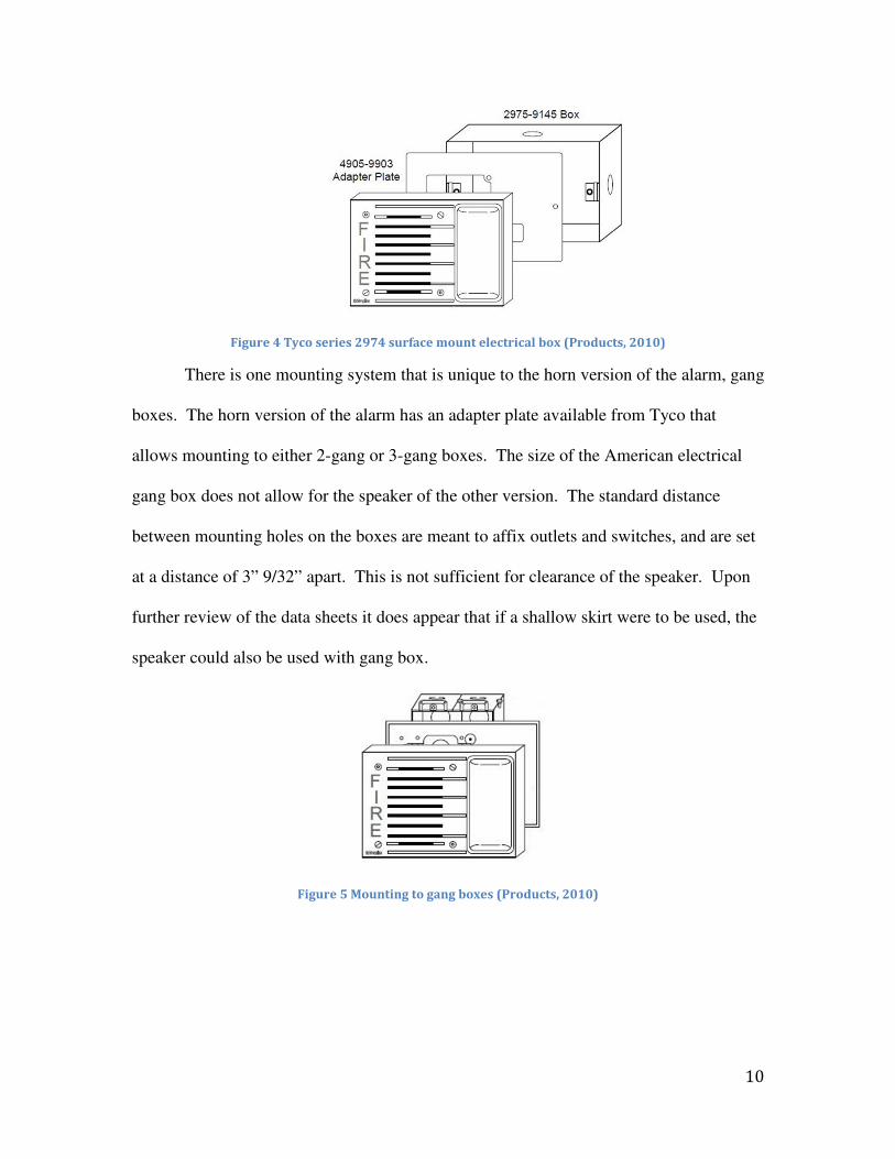
Figure 4 Tyco series 2974 surface mount electrical box (Products, 2010)
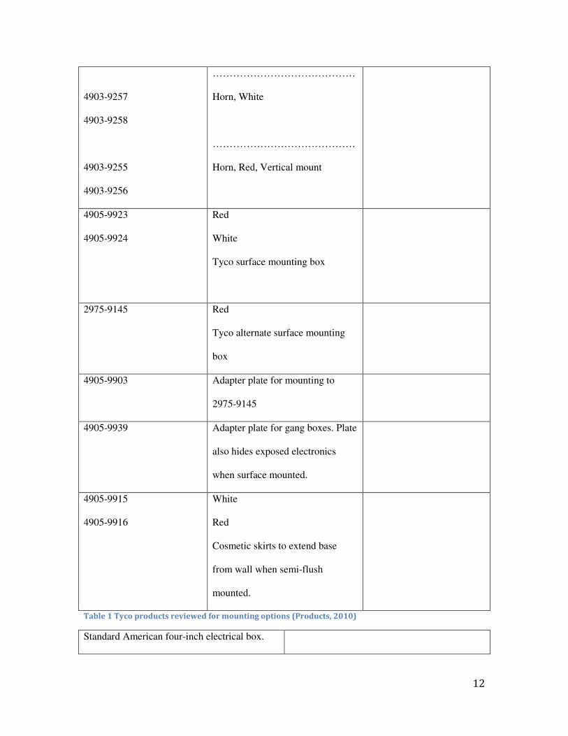
There is one mounting system that is unique to the horn version of the alarm, gang
boxes. The horn version of the alarm has an adapter plate available from Tyco that
allows mounting to either 2-gang or 3-gang boxes. The size of the American electrical
gang box does not allow for the speaker of the other version. The standard distance
between mounting holes on the boxes are meant to affix outlets and switches, and are set
at a distance of 3” 9/32” apart. This is not sufficient for clearance of the speaker. Upon
further review of the data sheets it does appear that if a shallow skirt were to be used, the
speaker could also be used with gang box.
Figure 5 Mounting to gang boxes (Products, 2010)

11
Figure 6 Illustration of plastic skirt (Products, 2010)
Below is a table showing all the Tyco made products from that data sheets used
for the background research of this product. The table includes all different
configurations of the notification unit and all mounting accessories and adaptors used in
the different mounting situations.
4903-9150
4903-9148
4903-9149
4903-9193
4903-9194
4903-9195
4903-9153
4903-9252
4903-9253
4903-9255
Speaker, Red
……………………………………
Speaker, White
…………………………………….
Speaker, Red, Vertical mount
……………………………………
Horn, Red
12
4903-9257
4903-9258
4903-9255
4903-9256
……………………………………
Horn, White
……………………………………
Horn, Red, Vertical mount
4905-9923
4905-9924
Red
White
Tyco surface mounting box
2975-9145 Red
Tyco alternate surface mounting
box
4905-9903 Adapter plate for mounting to
2975-9145
4905-9939 Adapter plate for gang boxes. Plate
also hides exposed electronics
when surface mounted.
4905-9915
4905-9916
White
Red
Cosmetic skirts to extend base
from wall when semi-flush
mounted.
Table 1 Tyco products reviewed for mounting options (Products, 2010)
Standard American four-inch electrical box.

13
1.5 inch depth
Standard American four-inch electrical box
extension ring. 1.5 inch depth
Standard American gang-able electrical box.
2.5 inch depth
Table 2 Standard American electrical boxes reviewed for mounting options (Products, 2010)
Patents
Finding patents that include part or all of our design and functions was started to
find any benchmarks in the design that we could follow. Patent research is also important
to make sure that any existing patents for similar devices are not infringed upon in any
way, making our design potentially illegal. After searching the United States Patent
database after key words "strobe, speaker alarm, mounting and cover", no existing design
that has combined a speaker strobe with another standalone strobe in different color was
found. However, various patents concerning mounting plates, mounting methods (with or
without fastener), electrical outlet and cover are also relative and instructive to our
design.
Injection molding
Injection molding is a manufacturing process that allows complex parts to be
created at relatively low costs. In the modern era of manufacturing, reducing costs is the
key to the success of any company. As products become more complex they in turn,
become more expensive to manufacture. When a product is constructed from
complicated geometry, it is usually broken down into smaller, constituent pieces, which
are much easier to create, and then assembled near the end of the production line.
Injecting molten plastic into the cavities of a mold and allowing it to solidify can achieve

14
more complex shapes achieved in single, eliminating the extra assembly steps. (何满才,
2005) Mold engineering is the process of optimizing the steps going from raw material to
part by finding ways to decrease cycle time, energy used, and raw material waste.
Injection molding processes are made up of three steps, Filling, Cooling, and
ejection. During the filling step, plastic is melted into liquid form and injected into the
mold cavities. Cooling then takes place starting by heat loss via convection by the walls
of the mold and is usually aided by cooling the mold rapidly with a coolant fluid. During
the last step, ejection, the mold is opened, the part is ejected and the mold setup is reset
for the next part (何满才, 2005; Boothroyd & Dewhurst, 1994).
Filling can further be broken down into several steps. The raw materials used in
the injection molding process are usually in the form of plastic pellets, commonly
polyethylene or polystyrene. The colors are mixed and melted inside the hopper, and
after homogenization in color and temperature are reached, injected via nozzle into the
waiting mold cavity. As the shot enters the mold, the pressure inside the cavity increases
as the fluid mass fills in the empty spaces. When the mold is filled, pressure increases
very rapidly and fluid flow rate drops while the molten material packs into the extremities
of the mold cavity. The speed and ability of the fluid to fill small gaps in the cavity are
determined by the properties of the molten fluid. Packing is the last stage of the filling
process and immediately afterward (also during, to a small degree), cooling begins
(何满才, 2005; Boothroyd & Dewhurst, 1994).
Cooling time makes up the longest part in any injection molding process, partly
because it begins the moment the fluid leaves the nozzle of the injector and comes into

15
contact with the mold surfaces. Cooling time is a function of the thickness of the part as
well as the design of the mold and it’s ability to conduct heat to the surrounding
atmosphere. One of the largest challenges of designing for cooling is planning for the
pressure drop that occurs when the injector nozzle is disconnected from the mold after the
packing phase. The gate of the mold can be a point of egress for the cooling plastic and if
it hasn’t already solidified enough to seal the pressurized material inside the mold, the
loss of material can occur causing waste and very possibly ruining the part. As the
material cools the pressure drops and eventually a ‘sealing point’ is reached when there is
no way material will escape from the gate opening and backflow is no longer an issue.
Determining the time it takes for the mod design to reach this point is very important for
controlling waste, energy, and cost (Boothroyd & Dewhurst, 1994)
The power used in creating an injection-molded plastic part is mostly used in the
ejection stage of the part. In order to keep the two halves of the mold coupled in such a
way that the pressure does not force the molten material to flash between the seals, large
amounts of force are required to press the mold together. The cooling system, along with
the weight of the steel mold, and taking into consideration that it is desired to have the
mold opened, ejected, and closed in the shortest possible time, make for a very power
intensive machine. Power consumption is just one factor in engineering the ejection
phase. The speed of the ejection phases is another critical factor in mold design. Mold
complexity determines the ease of which the part can be ejected. Equilibrium between
quality and economy must be reached for if the part is ejected too fast there is risk of
damaging the delicate part and possibly the mold. If it is too slow than time/money are
wasted in resetting the cycle (Boothroyd & Dewhurst, 1994)

16
Cost of Injection Molding
In order to minimize the costs in the product, an accurate method of estimating
injection-molding costs must be utilized. The three main costs related to injection
molding are material cost, machine cost, and mold cost. Material cost is the easiest to
calculate, as it only depends on the volume of the part and runner system and the unit
price of the material used to make the part. The material cost per part will always be
constant, regardless of how many parts are made. Machine cost is simply the hourly cost
of running the injection-molding machine divided by the number of parts the machine
can produce in one hour. The number of parts the machine can produce is derived from
the cycle time of a part, which includes the time for injecting plastic into the mold, the
time for the plastic to cool, and the time for the mold to open and close to let the new part
fall out and reset for another part to be made. Like material cost, the machine cost per
part is independent of how many parts are made, assuming that the molding machine
always operates at a constant rate. (Boothroyd & Dewhurst, 1994) Mold cost, the cost of
the base material for a mold and the labor associated with machining the cavity or
cavities of the mold depends on the size and complexity of the part and is the most
difficult cost to determine. However, using the equations found in Appendix B it is
possible to estimate how many hours it will take to machine the mold based on the
features and dimensions of the part. If the hourly rate a machine shop charges is known,
a fairly accurate estimate of the mold cost can be obtained. The key difference between
the mold cost and the material cost is that the mold cost is fixed for the life of the mold.
As long as the mold doesn’t deteriorate, the cost per part will decrease as the number of
parts produced increases. Thus, in order to truly optimize part cost, the number of parts

17
made with a single mold must be known. For small quantities, the mold cost will
represent a significant portion of the part cost, and should be minimized even at the cost
of adding material to the part. However, with increased production quantities the mold
cost per part will diminish and the material cost will become the most important factor.
For the purposes of this project, all three costs were estimated and production volume
was assumed to be 5000 units. However, during the selection of design only the material
costs were considered because the actual production rates are not known and also because
Tyco considers the purchase of molds to be investment capital and thus are treated
differently than production costs. (Boothroyd & Dewhurst, 1994)
Sheet metal
Sheet metal working is one of the machining processes, which forms sheet metal into
desired shape. It has applications in car bodies, airplane wings, medical tables, roofs for
building and many other things. By applying machining procedures such as stretching,
bending, punching and pressing, the original flat pieces or coil strips of metal are
manufactured into functioning sheet metal parts (詹友刚, 2006; Boothroyd & Dewhurst,
1994).
There are generally two sheet metal working methods. The traditional method uses
dedicated individual dies to realize the profile forming, piercing and bending of the sheet
metal. The other method uses computer numerically controlled (CNC) turret press where
series of punches are installed on a rotatable platform. The advantage of this method is
that it uses general-purpose punches and dies that can be used to manufacture a wide
range of different parts and the punches and dies fit into standard holders. These general-
purpose tools can be purchased from tool suppliers in a large variety of standard profiles

18
or made to custom order. The shortcoming is that bending should be carried out
individually on a press brake and the machining time is relatively longer than dedicated
dies.
For sheet metal working with dedicated dies, the cost mainly comes from:
1. The cost of raw materials
2. The cost of operating the machine.
3. The cost of the die sets.
The material cost depends on the material chosen and the part volume, i.e. area and
thickness of the sheet metal. (Boothroyd & Dewhurst, 1994)
The machine operation cost depends on the machine chosen and the manufacturing
time, which varies with the complexity of the part. The more procedures are required the
more time it would take. Detailed analysis procedure will be included in Appendix C.
And for each type of die cost always include a basic die set, which also add to the
cost of the sheet metal working. (Boothroyd & Dewhurst, 1994)
For sheet metal working with turret press and press brake, the cost is different from
that of dedicated dies in that it excludes the die sets cost since the turret press setup is
equipped with general-purpose punches and dies which can be used to manufacture a
wide range of different parts. (Boothroyd & Dewhurst, 1994)
In this case, the cost of the sheet metal working using turret press would depend
mainly on the complexity hence the machining time of the part. Detailed analysis
procedure will also be included in Appendix C

19
Objectives
The objective of this project was to design the plastic frame and mounting system
for an all-new emergency notification appliance, which combines the functions of a clear
strobe, amber strobe, and speaker.
Methodology
This being a project focused on the design of a new product, we decided to follow
Professor Robert Norton’s ten-step design process as a guide to take our design from
concept to reality. The steps have been altered to better fit the project, since this is an
international MQP, which has a corresponding PQP in the term leading up to the project
to prepare. The steps are:
Identification of need:
• The project information from Tyco stated we were to combine existing strobe and
speaker technology into an all new notification unit. The need for this unit was
left for our team to discover. The need is an update to current fire alarm
technology to provide clear instruction to the hearing impaired as well as the
fully-baled occupants of a building in case of emergencies where structured
evacuation strategies are necessary.
Background Research:
• Background research was done on Tyco’s existing product line and identifying
the gap where a new product was needed. Also research was done on

20
competitor’s products and patents, to find if anything similar was being developed
or on the market. We also visited Tyco’s facilities in America and China to get
information on how the design process of the company can be implemented by us
on this project. In order to help with the design phase, background research on
injection molding and sheet metal design procedures, as well as the cost analysis
associated with these was done during weeks 1-4 of the MQP. Background
research about ProEngineer: Wildfire 2.0 was necessary throughout the project to
ensure the quality of created files.
Goal Statement:
• Our goal statement was: Design a new fire alarm that incorporates the speaker,
clear strobe, and amber strobe of the older models, and combines them into one
unit.
Task Specifications:
• By the end of the PQP we had a list of task specifications that guided the creation
of the design. At the end of week 2 of MQP the list was altered slightly due to
new information and then finalized.
Ideation and Invention:
• Concepts for the positioning of the two strobe lights based on meeting
requirements set by the task specifications were finished and presented by end of
week one of the MQP.
Analysis and Selection:

21
• Analysis was done on the concepts was performed on the concepts and occurred
from start of week 2 and lasted until end of week 5. Analysis was performed in
two steps listed by importance to the project: 1. Conformation check to codes and
standards, 2. Cost analysis of the injection molded part. Concepts were then
eliminated using these processes. Firstly, any concept that failed step one was
eliminated from consideration. Secondly, production ready CAD files were
produced for the remaining concepts and detailed cost analysis methods were
performed. Selection of the final design based on economical advantage over
other concepts.
Detailed Design:
• During week 5 and six mounting accessories and adapter plates as well as their
cost analyses were created for the final design. The reason for waiting so late in
the project is that the accessories are dependent on the design of the unit and
cannot be created independently.
Prototype:
• During week six of the MQP a prototype of the plastic frame of the unit was
created by SJTU’s rapid prototyping machine out of photo setting resin.
Results:
The results of this project are documented in the MQP report which was created
over the entire span of the 8-week MQP

22
The first four steps of the project were completed during the PQP phase. Identification of
need was provided to us from Tyco and also our own research into the products offered
by the company. Most of the background research was done during PQP but some
background research was necessary during MQP due to unforeseen design elements. Our
goal statement was refined and finalized during our introductory meeting at Tyco in
China.
The project started with a meeting with our Tyco sponsors, Bob Lin and Helen
Han. We restated the work we have completed thus far with the PQP and our intentions
with the MQP. After combining our work with the feedback they provided, we were able
to form an updated set of goals for the project and begin work immediately.
Ideation and Invention
The design requirements that our product must conform to were updated and
restated.
1. Must be compatible with existing mounts.
2. Strobes must be positioned as not to interfere with one another.
3. Must incorporate 2 strobes (1 amber and 1 clear), as well as a speaker.
4. Must use the existing speaker and strobe components from previous models.
5. Strobes must be aligned in a configuration parallel to each other as well as the
floor.
6. Must not violate any codes and/or standards that the current product applies to.
7. Must support both flush and surface mounting systems.
8. The material cost of the new product must not add more than $5 US to the
existing product.

23
Using these specifications we able to form a clear concept of the basic shape of
the device, and came up with several configurations of lights and strobe that satisfied
the requirements 1-5. Requirement 7 was not considered at this point due to
insufficient data. Requirement 6 was thus far only considered insofar as not making
it impossible, but further considerations were at this point still needed. Five
configurations were produced and are shown below and are named concepts 1-5.
Figure 7 Concept 1
Figure 8 Concept 2

24
Figure 9 Concept 3
Figure 10 Concept 4
Figure 11 Concept 5
Analysis and Selection
We began the process of analyzing our concepts by verifying that each design
would satisfy the requirements we had previously established.
Requirement 1: Compatible with existing mounts

25
All configurations use the same mounting holes from the previous models, that is,
holes that match a standard American four-inch electrical box.
Note that concepts one and two both extent the mounting plane further from the wall
by a distance equal to the height of the strobe fixture. This consideration was made to
account for the extra space the speaker takes up and possibly eliminate the need for
an extension to the electrical box.
Requirement 2: Strobes must be positioned as not to interfere with one another.
In all concepts a distance equal to the height of the strobe offsets the planes in
which the two strobes are placed. This is to assure that the plastic lens in no way
interferes with the light emitted from the other strobe when in operation.
Requirements 3 and 4: Must incorporate 2 strobes (1 amber and 1 clear), as well as a
speaker.
Using ProEngineer as our CAD software, we were able to use existing models of
Tyco’s products to form the systems shown in concepts 1-5. There were no issues in
including spear or strobes from the older models.
Requirement 5: Strobes must be aligned in a configuration parallel to each other as well
as the floor.
This requirement is to satisfy that the pattern of light emitted from the strobe
matches the pattern from the previous model. Initially it was thought that by making the
strobes perpendicular a cost savings might be found, but light dispersion and conformity
to NFPA 72 might be violated.
Requirement 6: Must not violate any codes and/or standards that the current product
applies to.

26
Additional background research into NFPA 72, coupled with feedback from
Tyco’s fire detection division provided two bits of crucial information. Strobe lights in
fire alarm notification units must be positioned between eighty and ninety six inches from
the floor or they violated the code. Also, when walls in new buildings are constructed,
the contractors install the four-inch electrical, which the speaker mount to directly, at a
height of eighty inches from the floor. We deduced from this information that concepts
1, 2, and 3 all had the possibility of violating NFPA code, and were removed from
consideration, this left concepts 4 and 5 to be considered. We began the evaluation
process of concepts 4 and 5 by making finished CAD files in ProEngineer, that were
exact in detail and dimension to what the production model would be.
Figure 12 Concept 4, detail
Figure 13 Concept 5, detail

27
To develop a product that is compatible with the speaker and strobe components
of the previous models, it was necessary to inherit as many dimensions as possible from
the Tyco design. The dimensions of the pockets that the strobe circuits are enclosed by,
and which the lens snaps onto are repeated to the minute detail. Also the dimensions of
the gussets and ribs for the speaker attachment were inherited. The positions of the
mounting holes to attach the unit to the wall are fixed, as that is set by American
electrical code.
Cost Analysis
The two remaining concepts were then subjected to injection molding cost
analysis based on two methods. The first was the method taught to us during our courses
using formulas found in “Product Design for Manufacture and Assembly”. The second
being an online injection molding cost analysis site called http://www.custompart.net,
used only to check the validity of the formula we had used. The costs associated with
constructing each concept are found in the following table, and the complete breakdown
of formulas used is found in appendix B.
Concept Material Cost Per
Part ($)
Machining Cost
per Part ($) Mold Cost ($)
Total Cost Per
Part ($)
4 0.947 0.306 46933 10.63928
5 0.942 0.306 47685 10.78508
Table 3 Injection mold cost analysis for concepts 4, 5 (Boothroyd & Dewhurst, 1994)
Using this cost analysis matrix, we were able to eliminate concept four from
consideration, making concept 5 the first iteration of our final design. Looking back to
the table, it is clearly seen that mold costs can be large and can have a huge impact on the

28
cost per part of the product. There are some key factors in reducing mold cost. If mold
complexity is reduced, than the price of the mold is greatly reduced. Also, reduction in
projected area or volume of the part can also reduce the cost of the mold. Keeping these
things in mind, we first tried to reduce the volume of plastic that the part would require,
thereby reducing the shot size per part. To do this we designed a part that instead of
using two separate planes to separate the strobes, we offset the strobes by a sufficient
distance as to not interfere. The new design was called concept 6, and performed the
same cost analysis to obtain comparative data. (Boothroyd & Dewhurst, 1994)
Figure 14 Concept 6, detail
Concept Material Cost Per
Part ($)
Machining Cost
per Part ($) Mold Cost ($)
Total Cost Per
Part ($)
4 0.947 0.306 46933 10.63928
5 0.942 0.306 47685 10.78508
6 0.814 0.297 46399 10.39008
Table 4 cost comparisons for concepts 4, 5, 6 (Boothroyd & Dewhurst, 1994)
Concept 6 had advantages over the previous design as far as costs were
concerned, but Tyco has a certain aesthetic that they adhere to in this product line. Also
we cannot take the chance to potentially break any current or future NFPA 72

29
regulations, so for these reasons, this concept was eliminated. We applied the same
techniques to concept 5 to reduce the amount of plastic used per shot and found if we
moved the cosmetic lettering on the front of the part we could greatly reduce the
projected area of the part. This became iteration 2 of the final design, and we again
applied our cost analysis methods.
Figure 15 Concept 7, detail
Concept Material Cost Per
Part ($)
Machining Cost
per Part ($) Mold Cost ($)
Total Cost Per
Part ($)
4 0.947 0.306 46933 10.63928
5 0.942 0.306 47685 10.78508
6 0.814 0.297 46399 10.39008
7 0.895 0.306 45581 10.31700
Table 5 cost comparisons for Concepts 4, 5, 6, and 7
The last thing we tried before final selection was to find a way to reduce the
complexity of the mold, and by doing so, greatly reduce the cost. The most complex
feature on all concepts is the pockets where the strobe components attach to the plastic
frame.

30
Figure 16 Mold cavity complexity
These features have purposes, too allow the strobe circuit to snap into the plastic
frame, as well as covering and protecting these same components from the inside. These
features also provided the snap fittings for the lenses to lock onto when the unit is
installed. Since we were challenged to reduce cost as much as possible we opted to try a
sheet metal with escutcheon design similar in concept to the simplex product 4906-0009.
Figure 17 Tyco product 4906-0009 (Products, 2010)

31
Figure 18 Tyco product 4906-0009, exploded view (Products, 2010)
In such a design the strobe and associated circuitry and hardware are attached to a
sheet metal frame, then a cosmetic plastic escutcheon is snapped over to cover the
assembly. The idea of exploring such a design is to verify whether or not the increased
cost of sheet metal due to stamping and bending is offset and overcome by the reduced
mold cost due to greatly simplified cavities.
This led to yet another iteration of the final design in which we designed a sheet
metal frame, to which the components of the unit would attach. This would then attach to
the various electrical boxes and surface-mounting components via mounting holes
punched in the sheet metal. After the frame is attached to the wall a plastic escutcheon,
which in outward appearance is identical to our final design shape would be snapped on
to complete the installation. The mold for the escutcheon would be greatly simplified
when compared to the mold for the current of older designs. Pictured below is concept 8
with the corresponding sheet metal frame, along with the costs associated with producing
this product compared to the cost of concept 7.

32
Figure 19 simple plastic escutcheons, detail
Figure 20 Sheet metal frame for concept 8
Concept 7 Material Cost Per
Part ($)
Machining Cost
per Part ($) Tooling Cost ($)
Total Cost Per
Part ($)
7 0.895 0.306 45581 10.31700
Table 6 Cost analysis of concept 7 (Boothroyd & Dewhurst, 1994)
Concept 8 Material Cost Per
Part ($)
Machining Cost
per Part ($) Tooling Cost ($)
Total Cost Per
Part ($)
Plastic 0.944 0.306 31987 15.4488
Sheet metal 4.25 1.169 11972
Table 7 Comprehensive cost analysis of concept 8 (Boothroyd & Dewhurst, 1994)
It is immediately obvious upon looking at these tables that concept 8
would be a very poor choice. The mold cost is reduced very significantly, but it does not
offset the drastically increased cost due to the large sheet metal component, which alone
comes close to exceeding the requirement of being no more than five dollars more per
part to produce. This iteration was provided a challenge to save cost to the company, and

33
the failure in doing so brought more value in deciding concept 7 is the design to move
forward with.
Figure 21 Final Design
Detailed Design
A detailed CAD file of the final design was necessary before selection in order to
obtain accurate figure to use in injection mold cost analysis. In order to finish the part
however, mounting considerations must be made. It was learned from the background
research on the datasheets provided by Tyco that the older models were designed with
mounting holes to standard American four-inch electrical boxes for standard installation.
With the advent of speakers to the design, extension rings needed to be used to account
for the added depth. Also surface mounting considerations were made in cases where
retrofitting was necessary and the four-inch boxes were not in use. Finally adapter plates
were created to aid with surface mounting boxes as well as make the alarm compatible
with standard American multi-gang boxes.

34
Altogether, there are six different mounting situations that in order to be
compliant with the older models, and be backward compatible; the new design must
conform to.
1. Standard four-inch electrical box plus extension ring, both inside the wall, unit
flush mounted to the wall.
2. Standard four-inch electrical box plus extension ring, box flush with wall, and
ring extending out of wall. A distance equal will offset the unit from the wall to
the depth of the extension ring. This is a semi-flush mount and will require a skirt
to cover the distance from the base of the part to the wall.
3. Standard four-inch electrical box plus extension ring, both mounted outside the
wall. The unit will be offset a distance of both boxes. This is a surface mount.
And will require a deep skirt to cover the distance between the base of the part
and the wall.
4. Multi-gang boxes, 2-gang or 3-gang, mounted inside the wall. The unit will be
semi-flush mounted with a skirt to extend the speaker out from the wall, because
the diameter of the speaker magnet exceeds the opening of the standard gang box.
There will also be an adapter plate to go from the mounting holes that match the
four-inch boxes to the gang box mounting holes.
5. Tyco box 4905-9923/24 (identical dimensions) surface mount box, outside the
wall. The unit will be offset from the wall by a distance equal to the depth of the
box and require an adapter plate to cover the back of the unit since the new alarm
is larger than the previous models. This is necessary to comply with electrical
and fire codes.

35
6. Tyco box 2975-9145 surface mount box, outside the wall. The unit will be offset
from the wall by a distance equal to the depth of the box and require an adapter
plate to go from the four-inch box holes to the mounting holes on the box.
To make the previous alarms compatible with these situations two separate
adapter plates were designed, a shallow skirt, and a deep skirt. Since we had the
fortune of knowing ahead of time what the two adapter plates dimensions and
purposes were. We were able to design single adapter plate that combines the
functions of the two previous plates. The design of an adapter plate was necessary,
but we are able to save costs by combing the two into one.
Combination
Adapter
Material Cost Per
Part ($)
Machining Cost
per Part ($) Tooling Cost ($)
Total Cost Per
Part ($)
1.71 0.14 6888 3.2318
Table 8 Cost analysis of combination adapter plate (Boothroyd & Dewhurst, 1994)
Figure 22 Combination adapter plate, detail (詹友詹友詹友詹友刚刚刚刚, 2006)
For semi-flush mounting, a shallow shirt was needed that corresponded to the
shallow skirt of the previous models. Since the base area of the final design is larger
than the previous models it was necessary to design a new skirt. Also since the

36
projected depth is different for separate situations, an additional deep skirt needed to
be designed as well. With the design of these accessories, the final design is
compatible with all the mounting situations that the previous model conformed to.
Figure 23 Shallow Skirt, detail (何何何何满满满满才才才才, 2005)
Figure 24 Deep Skirt, detail (何何何何满满满满才才才才, 2005)
Prototype
One of the optional deliverables to Tyco at the end of the project was a prototype
of the final design. A first generation prototype assists in finding potential errors in
the design, or potential hazards of the injection molding process. At the Xujui
campus of Shanghai Jiao tong University; there is a rapid prototyping facility within
the medical technologies school. With the help of this department, we were able to
construct a prototype of the final design not only for purposes of verifying fit of the

37
components, but to also present a tangible product to our peers and sponsors at the
end of the project.

38
Results
Tyco requested three deliverables for the end of the project: 3D ProEngineer files
for the notification unit and all mounting accessories that were designed, 2D part
drawings for the notification unit and all mounting accessories that were designed, and, if
time and budget permitted, a physical prototype of the plastic base. Since all of the parts
were designed using ProEngineer, 3D data was already available and 2D drawings were
constructed from the information in our existing CAD files in ProEngineer. The resin
prototype was made in one of the 3D printers at SJTU's Plastic Forming Division.
In total, four different parts were designed for the project: the plastic base for the
notification unit, to which holds the speaker and strobe assemblies are mounted, a
shallow plastic skirt, to aid in semi-flush mounting, a deep skirt, to facilitate a full surface
mount with a four-inch electrical box with extension, and a sheet metal adapter plate,
which is a cost effective method of combining the two existing adapter plates, to ensure
compatibility with all other semi-flush and surface mounting situations. All six mounting
situations can be achieved with an added material cost of less than $5. The products,
along with their material costs are below in table 9.
Dual Strobe/Speaker Notification Unit $ 0.895
Sheet Adapter Plate $ 1.71
Shallow Skirt $ 0.408
Deep Skirt $ 0.714
Table 9 material costs of designed products (Boothroyd & Dewhurst, 1994)

39
As is shown in the table the most expensive mounting option is the combination of the plastic base
and the combination adapter plate. This would be used least often, only during a retrofit of the alarm
systems in a building with existing and/or unchangeable electrical conduit systems, in which the
former speaker/strobe device were being replaced by the dual color speaker/strobe device and would
utilize the existing surface mount boxes.

40
Conclusion
A product that has the ability to notify both the hearing and the hearing impaired
of fires and provide more specific instructions for evacuation and emergency situations is
a necessary step in the evolution of fire alarms. When used in conjunction with
electronic message boards or other notifying devised for the hearing-impaired, the dual
color speaker/strobe can provide detailed evacuation instructions while still being
compliant with the ADA's requirements. As buildings become larger and evacuations
become more complicated, this product will likely become a standard in large public
buildings.
Since it if the first product of its kind in the American market, it will help Tyco
offer a more complete line of notification devices and maintain its position as a leader in
the fire protection industry. The cost-minimizing techniques used during the project will
ensure that the device can be produced economically even if Tyco's competitors build
similar products.

41
Appendix A - Performance Specifications
The following performance specifications were used as selection criteria for the
different concepts and designs. Some of the specifications were given by Tyco, and some
of the specifications were determined by the design team as a result of research on
existing Tyco products and codes from organizations such as NFPA (National Fire
Protection Association), UL (Underwriters Laboratories, and ADA (Americans with
Disabilities Act).
1. Must be compatible with existing mounts
2. Must support both flush (semi-flush) and surface mounting
3. Strobes must be positioned so as not to interfere with one another
4. Must have two different color strobes and a speaker appliance
5. Must use existing speaker and strobe assemblies
6. All designed parts must be manufacturable
7. Intended Market: Commercial
8. Cost: $5 more than the two existing products
9. Operating environment: indoors
10. Materials: Injection-molded plastic and industrial electrical mounting plates

42
Appendix B - Injection Molding Cost Estimation
The following equations were used to estimate the cost of the plastic parts that
were designed. We constructed a spreadsheet in excel with the relevant formulas and
input the necessary parameters of each design into the spreadsheet to calculate the total
part cost. Parameters of each design were measured from the CAD models we generated.
Injection molding cost of a part
C =Cmaterial +Crts /n+Cmold /Nt (1)
Cmaterial : cost of thermoplastic per component (including runners) [$]
Cr: operating cost of injection molding machine [$/hour]
ts: cycle time [sec]
n: number of cavities in the mold
Cmold: cost of mold [$]
Nt: total number of production
Material cost
Cmaterial =cp⟩V(1+fr)
(2)
Cp : cost of thermoplastic [$/kg]
43
ρ: density of thermoplastic [kg/m3]
V: volume of part to be injection molded [m3]
fr: runner volume rate
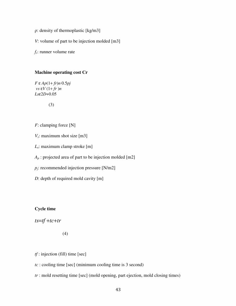
Machine operating cost Cr
F ε Ap(1+ fr)n⋅0.5pj
vs εV (1+ fr )n
Lsε2D+0.05
(3)
F: clamping force [N]
Vs: maximum shot size [m3]
Ls: maximum clamp stroke [m]
Ap : projected area of part to be injection molded [m2]
pj: recommended injection pressure [N/m2]
D: depth of required mold cavity [m]
Cycle time
ts=tf +tc+tr
(4)
tf : injection (fill) time [sec]
tc : cooling time [sec] (minimum cooling time is 3 second)
tr : mold resetting time [sec] (mold opening, part ejection, mold closing times)

44
tf =2V(1+fr)n⋅pj/Pj
(5)
2
max
2
4( )ln
( )i m
c
x m
h T Tt k
T Tπ α π
−=
−
(6)
1 1.75 (2 0.05) /r d st t D L= + +
(7)
Pj : injection power [W]
k: geometry correction factor; k = 1 for rectangular wall,
k = 2/3 for circular wall
hmax: maximum wall thickness [mm] (thinner is better!)
Tx: recommended part ejection temperature [oC]
Tm: recommended mold temperature [oC]
Ti: polymer injection temperature [oC]
α: thermal diffusivity coefficient [mm2/sec]
td: dry cycle time [sec]
Ls: maximum clamp stroke [m]
Mold cost
1
m
mold b cC C C n= +
(8)

45
Cb : cost of mold base [$]
Cc1 : cost of single-cavity mold [$]
n: number of cavity mold
m: multi-cavity mold index = 0.7
Mold base cost
C =1000+0.45Ah0.4
(9)
Ac: surface area of mold base cavity plate [cm2]
hp: combined thickness of cavity and core plates in mold base [cm]
Cost of single-cavity mold
Cc1 =R(Me +Mpo +Mx +65ns +150ni +250nu +Ms +Mt +Mtex +Mp) (10)
R: rate of mold manufacturing = $60/hour
ns: number of side pulls required
ni: number of internal core lifters
nu: number of unscrewing device
Me: Manufacturing hours of ejection system
Mpo: Manufacturing hours of cavity and core (size factor)
Mx: Manufacturing hours of cavity and core (geometrical complexity factor)
Ms: Additional mold manufacturing hours due to surface finish
Mt: Additional mold manufacturing hours due to tolerance

46
Mtex: Additional mold manufacturing hours due to texture
Mp: Additional mold manufacturing hours due to parting surface
Me =2.5 sqrt (Ap )
(11)
1.25 0.085po pM A= +
(12)
Ap : projected area of part to be injection
molded [cm2]
Mx =45(Xi +Xo)1.27
(13)
Xi: complexity of inner surface
Xi=0.01Nsp +0.04Nhd
(14)
Nsp: number of surface patches in inner surface (ignore small blending surfaces and parting surface)
Nhd: number of holes and depressions in inner surface
Xo: complexity of outer surface, calculated the same way as Xi
Ms = fs(Me +Mpo +Mx)
(15)

47
( )t t x
M f M=
(16)
0.05( )tex e po xM M M M= + +
(17)
Mp=fp (Ap)
(18)
fs: surface finish cost factor
ft: tolerance cost factor
fp: parting surface cost factor
Optimum number of cavities per mold
n=(Ntk1ts /mCc1)1/(m+1)
(19)
k1 = 25; m = 0.7
need to guess ts (cycle time, which depends on n) initially to find n
Nt: total number of production
Cc1 : cost of single-cavity mold
(Boothroyd & Dewhurst, 1994)

48
Appendix C - Sheet metal cost analysis equations
A spreadsheet similar to the one used to estimate the cost of injection molded parts was
made to estimate the cost of the sheet metal parts. Parameters were also taken from the
relevant CAD models and input into a spreadsheet based on the following equations.
Cost of individual dies:
For each type of die cost always include a basic die set.
120 0.36ds u
C A= + (1)
where
dsC = die set purchase cost, $
uA = usable area, cm2
When determining Au, leave enough margins (typical value is 50mm) to both side of the
part for securing of the die plate and installation of strip guides.
A system for estimating the cost of tooling includes the time for manufacturing the die
elements and for assembly and tryout of the die. Assembly includes custom work on the
die set, such as the drilling and tapping of holes and the fitting of metal strips or dowel
pins to guide the sheet metal stock in the die.
Profile complexity is measured by index pX as

49
2 /( )pX P LW= (2)
where
P = perimeter length to be sheared, cm
L,W = length and width of smallest rectangle which surround the punch, cm
For a blanking die, or a cut-off die L and W are the length and width of the smallest
rectangle which surrounds the entire part. For a part-off die, L is the distance across the
strip while W is the width of the zone which is removed from between adjacent parts. For
all cases, a minimum punch width W of about 6mm should be allowed to ensure
sufficient punch strength.
According to the complexity index, we can give a basic manufacturing time po
M , which
will be used as a base for further estimation see below.
Table 10 Estimation of manufacturing points as a function of complexity (Boothroyd & Dewhurst, 1994)
Then the basic manufacturing time should be multiplied by two correction factors:
lwf = plane area correction factor

50
df = die plate thickness correction factor
P.S. These factors are based on blanking dies. If we need get the estimation of cut-off die
or part-off die, a new modification factor should be involved, which will be discussed at
the end of this section.
lwf can be found according to the following chart.
Table 11 Estimation of correction factor (Boothroyd & Dewhurst, 1994)
df depends on the die plate thickness, which is recommended by the following
equations:
9 2.5 ln(( / ) )h
d msh U U V= + × , mm (3)
where
U = the ultimate tensile stress of the sheet metal to be sheared
Ums = the ultimate tensile stress of annealed mild steal
V = required production volume, thousands
h = sheet metal thickness, mm
Then d
f can be defined as:
max{0.5 0.02 ,0.75}d d
f h= + (4)

51
Thus the manufacturing time pM for a blanking die are given by
Mp = fd flwMpo ,h,h (5)
where
poM = basic manufacturing time, h
lwf = plane area correction factor
df = die plate thickness correction factor
the manufacturing time for a cut-off die is approximately 12% less than for blanking
the manufacturing time for a part-off die is approximately 9% less than for blanking
Individual dies for piercing operations
A piercing die is essentially the same as blanking die except that the material is sheared
by the punching action to produce internal holes or cut-outs into the blank. The
estimation of manufacturing time involves three parts: basic manufacturing time, custom
punch manufacturing time and standard punch manufacturing time.
Firstly, the basic manufacturing time is given by
Mpo =23+0.03LW, h (6)
where
L, W = length and width of the rectangle which encloses all the holes which are to be
punched, cm

52
Secondly, the custom punch manufacturing time is given by
Mpc =8+0.6Pp +3Np, h (7)
where
Pp = total perimeter of all punches, cm
Np = number of punches
Lastly, standard punch manufacturing time is given by
Mps =KNp +0.4Nd , h (8)
where
K=2 for round holes
=3.5 for square, rectangular or obround holes
Np = number of punches
Nd = number of different punch shapes and sizes
So the total estimated manufacturing time is the sum of all the above three parts.
Individual dies for bending operations
The basic manufacturing time is given by
(18 0.023 ) (0.9 0.02 )poM LW D= + × + , h (9)
where
L, W = length and width of rectangle which surrounds the part, cm
D = final depth of bent part, cm, or 5.0, whichever is larger.
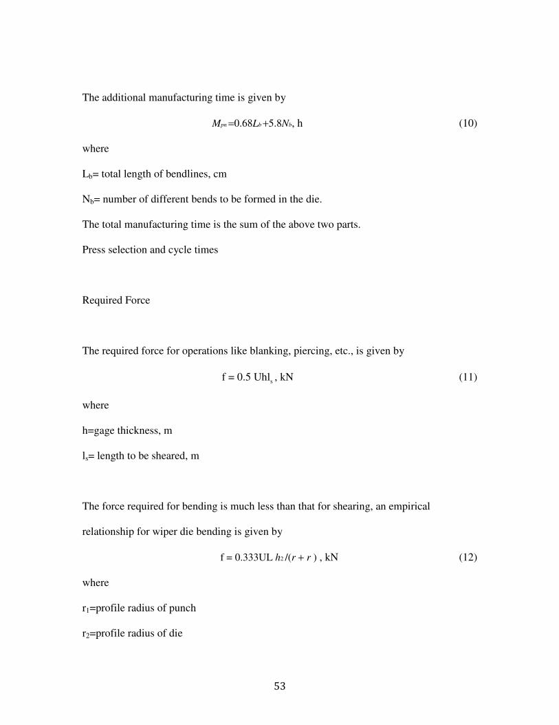
53
The additional manufacturing time is given by
Mpn =0.68Lb +5.8Nb, h (10)
where
Lb= total length of bendlines, cm
Nb= number of different bends to be formed in the die.
The total manufacturing time is the sum of the above two parts.
Press selection and cycle times
Required Force
The required force for operations like blanking, piercing, etc., is given by
sf = 0.5 Uhl , kN (11)
where
h=gage thickness, m
ls= length to be sheared, m
The force required for bending is much less than that for shearing, an empirical
relationship for wiper die bending is given by
f = 0.333UL h2 /(r + r ) , kN (12)
where
r1=profile radius of punch
r2=profile radius of die

54
Cycle time
The time for loading and unloading a blank or part can be given by
t = 3 . 8 + 0 . 1 1( L + W ), s (13)
where
L, W= rectangular envelope length and width, cm
P.S. For shearing operation, which automatic press ejection would be appropriate, 2/3 of
time given above should be used.
Turret press working
Machining cost estimation of using a Turret press
Time studies carried out on a variety of turret press parts suggest that an average of 0.5s
per his is appropriate for early cost estimating where hole spacing is of the order of
50mm or less. For large parts with significantly greater distances between holes, extra
sheet movement times of 0.1s for each additional 50mm can be added.
The punching time per part is estimated to be
t1 = 0.5Nh, s (14)
Nh= number of hits for one part

55
The loading plus unloading time can be given by
t2 =2+0.15(L+W), s (15)
L,W = the whole sheet length and width, cm
The time per part consumed can be expressed as t1 + t2 / n , where n is the number of the
parts on a whole sheet metal. Then we can get the machining cost by multiplying this
time with the machine rate from above equation.
Machining cost estimation of using a press brake
Empirical relationship for brake bending time can be given by
2(1 ) 0.05(2 )( )b b
t N N L W= + + + + , s (16)
Where
Nb= number of required bending operations
L,W = length and width of part, cm

56
Appendix D - Glossary of Terms
During the background research for the project, we encountered the following
words which were necessary to be familiar with. When any of the following words
appear in the paper, they use these definitions.
Candela – Term describing the intensity of the strobe light. The Simplex 4903-0016
strobe is available in 16, 30, and 110 candelas. 15 are the minimum required by law in
most areas.
VDC – Volts of Direct Current. The Simplex 4903-0016 runs on 24 VDC
Watt – Describes the power output of the speaker. Can range from .25 to 2 Watts.
VRMS – Root Mean Square Voltage, or the effective DC voltage. The Simplex 4903-
0016 can run on either 25 or 70.7 Volts RMS. For instance, UL standard 1971 requires
16-33 VDC and 25 VRMS qualifies.
Free Run and Synchronized – The strobe in the unit can either be configured to run in
Free Run mode, in which it blinks independently, or Synchronized with other units in the
building. This is done to reduce the chances of causing epileptic seizures.
UL Standard 1971 – UL code covering “Signaling devices for the hearing impaired”
UL Standard 1480 – UL code covering “Speakers for Fire Protective Signaling
Systems”
Alarm: A warning of danger
Alert Tone: An attention getting signal to alert occupants of the pending transmission of
a voice message.

57
Average Ambient Sound Level: The rms, A-weighted sound pressure level measured
over the period of time that any person is present.
Emergency Voice/Alarm Communications: Dedicated manual/auto equipment for
originating and distributing voice instructions, as well as alert ant evacuation signals
pertaining to a fire emergency, to the occupants of the building. Note—NFPA 72 does
not require voice, but building codes might require voice in the aid of systematic
evacuations.
Mass Notification System: A MNS may use intelligible voice communications, visible
signals, text, graphics, tactile (touch or vibration), or other methods. The system may be
used to initiate evacuation or relocation or to provide information to occupants. The
system may be intended for fire, weather, terror, etc. emergencies or any combination.
The system can be manual/auto, have multiple access points, and be wired/wireless.—
related to above
Signal: Status indication communicated by various means.
58
Alarm: signal indicating an emergency condition or alert that requires action
Delinquency: signal indicating need for action in connection with supervision.
Evacuation: distinctive signal intended to be recognized by the occupants as
requiring evacuation of the building. Note: NFPA 72 requires 3-pulse temporal
pattern that meets the standards of ANSI S3.41, American National Standard Audible
Emergency Evacuation Signal.
Fire Alarm: signal initiated by device such as fire alarm box, auto detector, water
flow switch, etc.
Zone: A defined area within the protected premises. Note: a zone can define an area
where signals can be received, or an area where signal is sent.
Injection Molding: Method of producing plastic parts in which a thermoplastic material
is heating to its melting point and forced into a mold which has been cut in the shape of
the desired part. Once the material cools, the mold is pulled apart and the part is ejected.
Sprue: A passage in a mold base through which the liquid material is injected into the
mold cavity.
Runner: Small passage in a mold that connects the sprue to the one or more cavities in
the mold.
Mold Base: Set of metal plates in which cavities have been machined to match the
feature of a desired part.
Parting Plane: Location at which the two halves of the mold join together. When the
part is ejected, the halves separate at the parting plane.

59
Cavity: Depression in a mold that has been machined out to produce one part. Molds
can have one or more cavities depending on how many parts they produce in a single
shot.
Shot Size: Amount of molten material that is injected into the mold during each cycle of
the mold. Includes volume of each cavity as well as the volume of the sprue and runners.
Clamp Force: Amount of force required to hold the two halves of the mold together
while the molten material is injected into it.
Mold Cost: Cost of purchasing the raw materials to make a mold plus the cost of
machining the necessary cavities, sprue, and runners into the mold base.
Machine Cost: Cost associated with running the injection-molding machine, expressed
in dollars per hour. Includes the cost of electricity consumed by the machine as well as
the labor cost of a worker running the machine.
Material Cost: Cost of material required for one cycle of the injection-molding machine.
Equal to the unit price of the material multiplied by the shot size, although material
associated with the sprue and runners can be recycled.
Dedicated Die: Method of manufacturing sheet metal parts in which a metal die is cut to
the shape of a desired part and forced against a piece of sheet metal, cutting a part to
exactly the outline of the die. Usually used for high-volume sheet metalworking.
Turret Press: Device used to manufacture sheet metal parts in lower volume than
dedicated dies. A computer-controlled press contains multiple dies, which can generate a
variety of standard shapes.
Die-Forming: Method of forming bends in sheet metal in which a die is made to produce
a specific bend pattern in a sheet metal part. Used when high volume of parts is needed.

60
Press Brake: Machine, which can produce a variety of bends in sheet metal parts, but
must be setup and operated manually. Used for low volumes of sheet metal parts, which
require bends.

61
Appendix E - Codes Relevant to project (reference)
It is important for the product to adhere to all of the codes and standards that the
previous Tyco products adhered to. In order to achieve this, we inherited many features
from the original product and became familiar with the codes and standards to make sure
that any modifications we made did not affect the product’s compliancy with the codes.
All of the codes and standards that we researched are below.
Book: NFPA 101 Life Safety Code Handbook ISBN 978-087765826-9
• A fire alarm system required for life safety shall be installed, tested and
maintained in accordance with NFPA 70, NFPA 72. Pg356
• All systems and components shall be approved for the purpose for which they are
installed. Pg356
o In the form of test reports issued by FM Global (insurance), UL
• All new alarms must be powered by the building’s electrical system; they cannot
rely on battery power. Pg361
• NFPA 72 specifies the audibility requirements for alarm signals in sleeping areas.
Audible appliances must have a sound level at least 15dB above average ambient
level, 5dB above the maximum sound level having a duration of at least 60
seconds, or a level of 75dB, whichever is greater. Pg362
• Visible notification is not required in stairwells or elevators. Stairs are a point of
egress and thus it is not necessary to inform people already evacuating-plus, the
system invites confusion in a crowded stairwell. When elevator doors open,

62
people will see/hear notification and egress. Pg364
• In large volume spaces (stadiums, etc.)-Occupant load of greater than 1000 it is
recognized that strobes are not as effective for the hearing impaired and some sort
of improved notification system is required. Pg365
• Code 9.6.3.6.1 the general evacuation signal shall operate throughout the entire
building. Pg365
• Code 9.6.3.6.2 where total evacuation is impractical due to building
configuration, only the occupants in the affected zones shall be notified initially.
Provisions shall be made to selectively notify other zones to afford orderly
evacuation of entire building.pg365
• Evacuation plans consider these parameters: building compartmentalization,
detection and suppression systems, and number/arrangement of means of egress.
Pg365
• Note for high rise-Order of evacuation is 1.Fire floor, 2.Floor immediately above,
3.Floor immediately below, 4.Remaining floors as fire develops. Pg365
o Conclusion: Training plans (fire drills) must be developed for these
situations in order to reduce panic. Our design can significantly reduce
this training time for large occupancy buildings. No one is comfortable
remaining in a building when they find out it is on fire (or other
emergency)
• In places where age, disability, or restraint is an issue, a private alarm mode may
be used. This alarm mode notifies the staff, or a particular unit of the building of
a fire or emergency via coded fire alarm signal. Then the people in charge of

63
responding initiate an evacuation plan for that situation. Pg365
• Alarms throughout the building should be the same volume, frequency, and sound
at the same duty cycle to avoid confusion. Pg367
• Code 9.6.3.9.2 Automatically transmitted or live voice announcements shall be
permitted to be made via a voice communication or a public address system that
complies with the following: (1) Occupant notification-live or recorded, shall be
initiated at a constantly attended receiving station by personnel trained for
emergency response. (2) An approved secondary power supply for other than
previously existing systems. (3) Shall be audible above expected ambient noise
level. (4) Emergency announcements take precedence above all other
announcements. Pg367
• Things approved for above voice- assembly occupancies, malls, existing
mercantile occupancies, existing bulk merchandise retail buildings, existing
business occupancies. Note that these buildings usually have a public address
system installed. Pg367.
• NPFA 72: National Fire Alarm Code Handbook isbn 978-087765719-4

64
Bibliography
何满才. (2005). 模具设计——Pro/ENGINEER Wildfire 中文版实例详解 (1st ed. ed.).
人民邮电出版社.
詹友刚. (2006). Pro/ENGINEER中文野火版2.0钣金设计教程. 机械工业出版社.
Boothroyd, G., & Dewhurst, P. (1994). Product Design for Manufacture and Assembly.
Dekker.
Chang, T.-C., & Richard A. Wysk, &. H.-P. (2006). Computer-aided manufacturing (3rd
ed. ed.). Prentice Hall.
Norton, R. L. (2007). Design of machinery: An introduction to the synthesis and
analysis of mechanisms and machines (4th ed. ed.). McGraw-Hill Companies.
Products, T. F. (2010). TYCO INT. Retrieved March 2010, from http://www.tyco-
fire.com/