design of knuckle joint -...
TRANSCRIPT
Design of Knuckle Joint • A knuckle joint is used to connect two rods
which are under the action of tensile load, when
small amount of flexibility or angular moment
is necessary.
• The line of action of load is always axial.
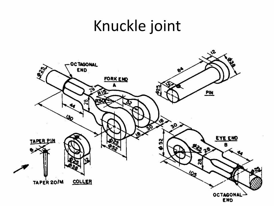
• The knuckle joint consist of three major parts.
a) Single eye b) Double eye c) Knuckle pin
• The single eye is formed at the one end and double eye is formed at the other end of the rod.
• The single eye fit into fork or double eye, both the parts are connect by pin inserted through eye.
• The knuckle pin has a head at one end and collar and taper pin or split pin at other end.
• The ends of the rod are of octagonal forms for improving the gripping at the time of repairs.
• Knuckle Joint Video
• Function of Split pin –
It holds collar and prevent lifting or ejecting the
knuckle pin from the joint.
Applications of knuckle Joint –
1. Tie rod of roof truss
2. Link of roller chain
3. Tension link in bridge structure
4. Tie rod joint of jib crane.
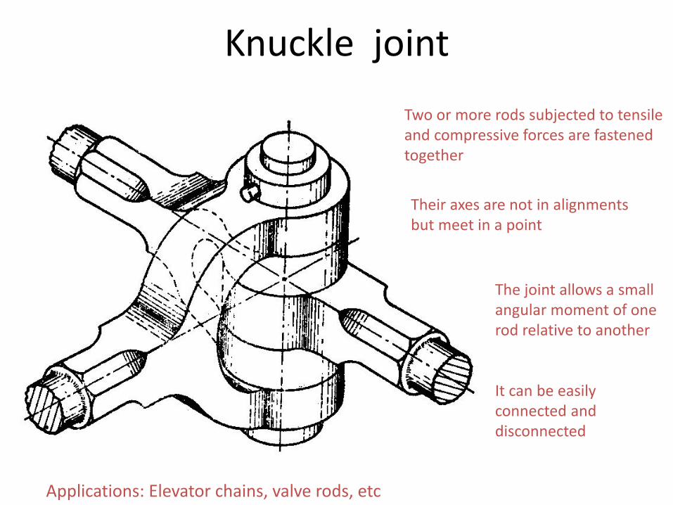
Knuckle joint
Two or more rods subjected to tensile and compressive forces are fastened together
Their axes are not in alignments but meet in a point
The joint allows a small angular moment of one rod relative to another It can be easily connected and disconnected
Applications: Elevator chains, valve rods, etc
Knuckle joint
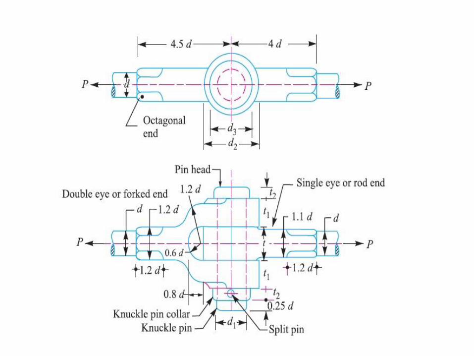
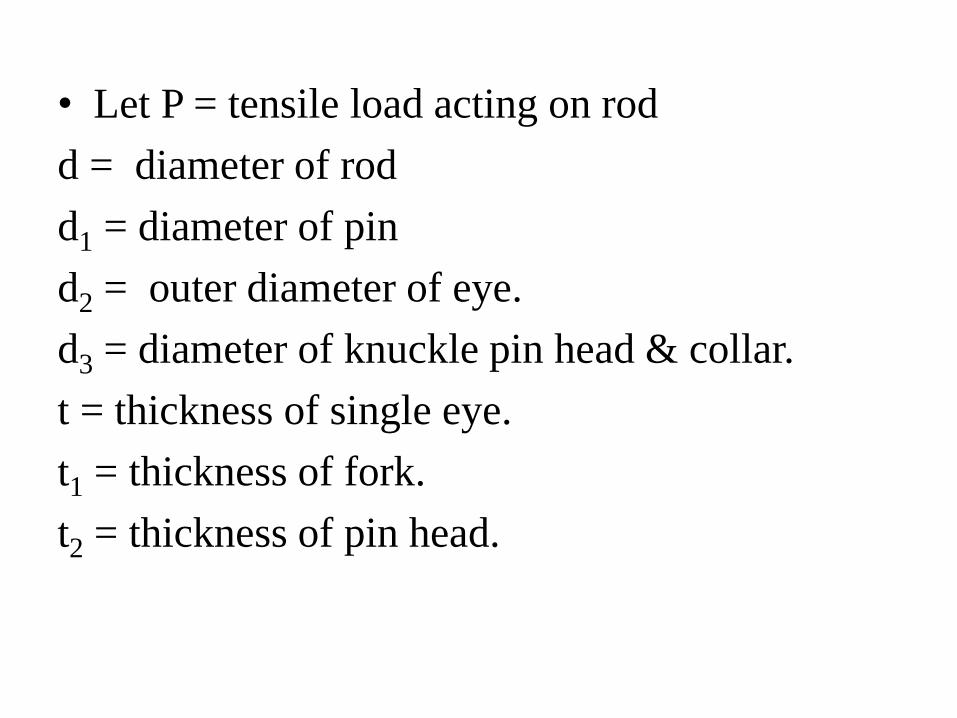
• Let P = tensile load acting on rod
d = diameter of rod
d1 = diameter of pin
d2 = outer diameter of eye.
d3 = diameter of knuckle pin head & collar.
t = thickness of single eye.
t1 = thickness of fork.
t2 = thickness of pin head.
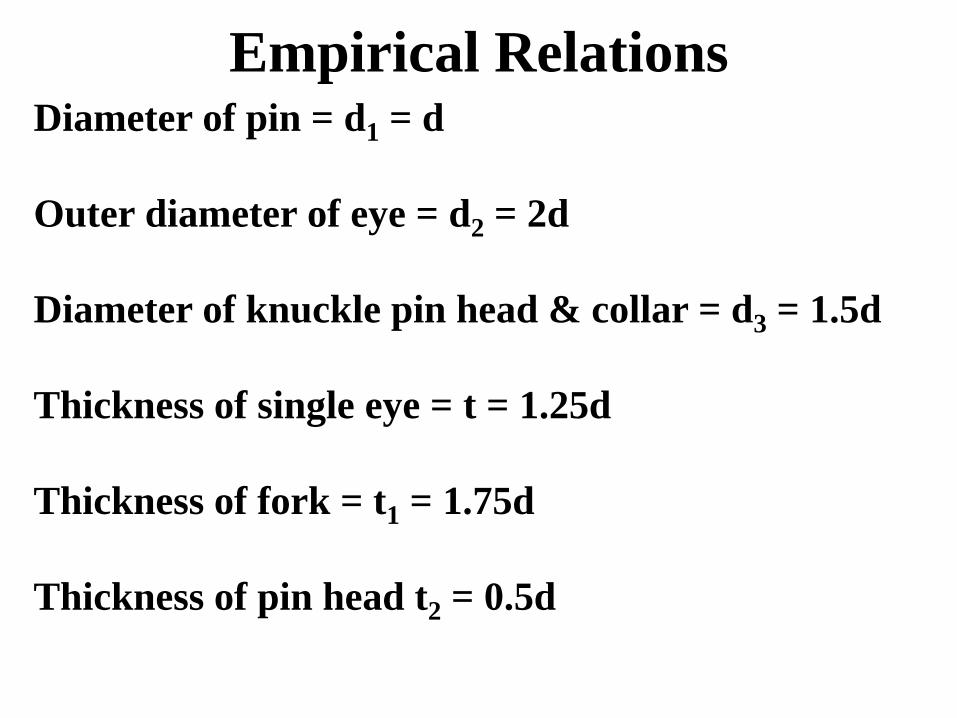
Empirical Relations Diameter of pin = d1 = d
Outer diameter of eye = d2 = 2d
Diameter of knuckle pin head & collar = d3 = 1.5d
Thickness of single eye = t = 1.25d
Thickness of fork = t1 = 1.75d
Thickness of pin head t2 = 0.5d
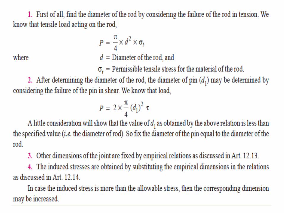
Design Procedure
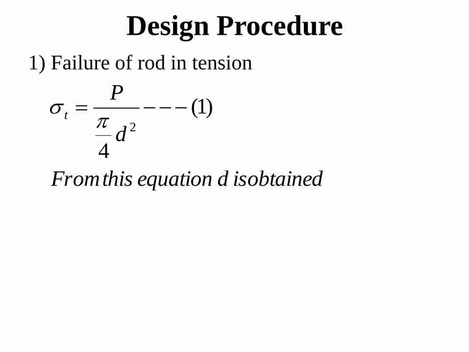
1) Failure of rod in tension
isobtaineddequationthisFrom
d
Pt )1(
4
2
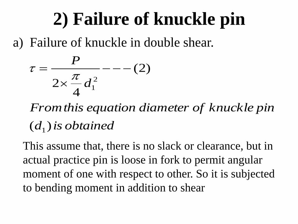
2) Failure of knuckle pin
a) Failure of knuckle in double shear.
obtainedisd
pinknuckleofdiameterequationthisFrom
d
P
)(
)2(
42
1
2
1
This assume that, there is no slack or clearance, but in
actual practice pin is loose in fork to permit angular
moment of one with respect to other. So it is subjected
to bending moment in addition to shear
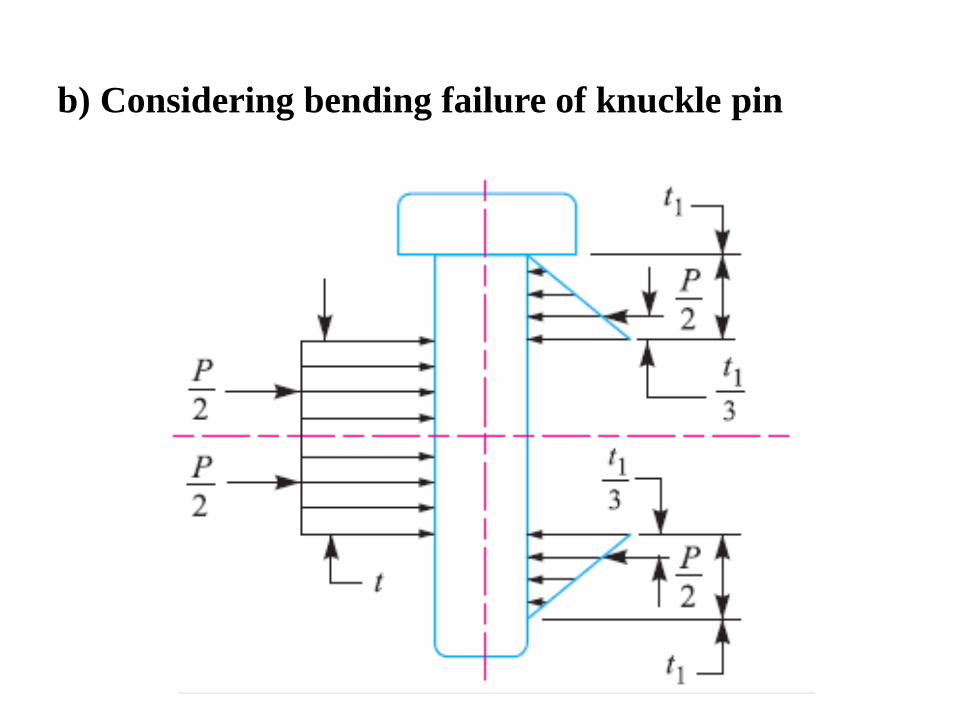
b) Considering bending failure of knuckle pin
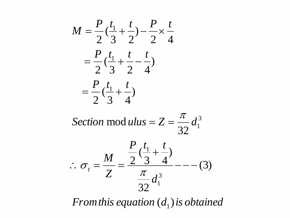
obtainedisdequationthisFrom
d
ttP
Z
M
dZulusSection
ttP
tttP
tPttPM
t
)(
)3(
32
)43
(2
32mod
)43
(2
)423
(2
42)
23(
2
1
3
1
1
3
1
1
1
1
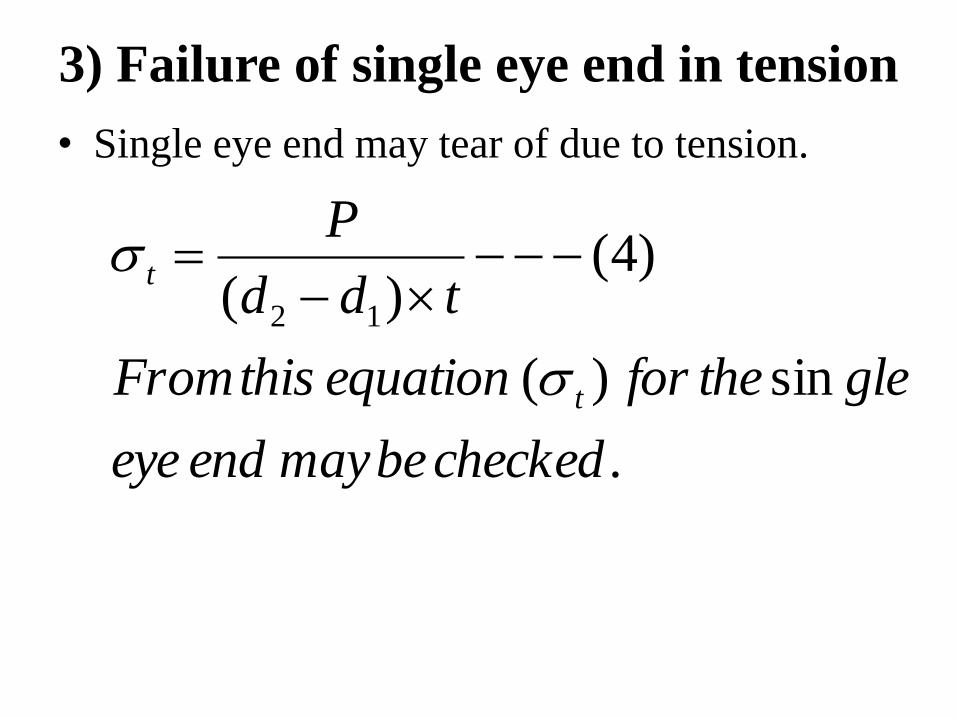
3) Failure of single eye end in tension
• Single eye end may tear of due to tension.
.
sin)(
)4()( 12
checkedbemayendeye
gletheforequationthisFrom
tdd
P
t
t
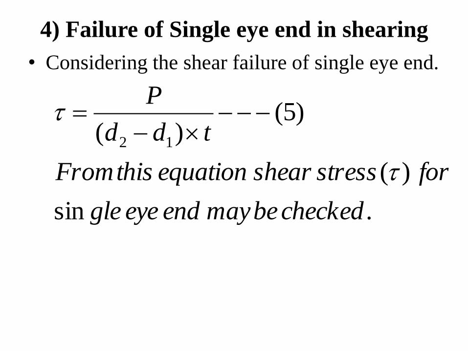
4) Failure of Single eye end in shearing
• Considering the shear failure of single eye end.
.sin
)(
)5()( 12
checkedbemayendeyegle
forstressshearequationthisFrom
tdd
P
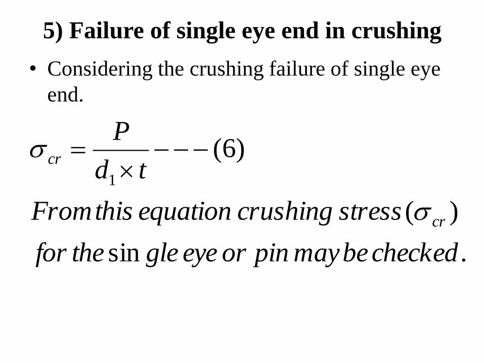
5) Failure of single eye end in crushing
• Considering the crushing failure of single eye
end.
.sin
)(
)6(1
checkedbemaypinoreyeglethefor
stresscrushingequationthisFrom
td
P
cr
cr
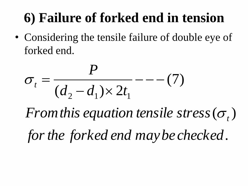
6) Failure of forked end in tension
• Considering the tensile failure of double eye of
forked end.
.
)(
)7(2)( 112
checkedbemayendforkedthefor
stresstensileequationthisFrom
tdd
P
t
t
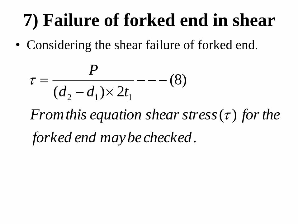
7) Failure of forked end in shear
• Considering the shear failure of forked end.
.
)(
)8(2)( 112
checkedbemayendforked
theforstressshearequationthisFrom
tdd
P
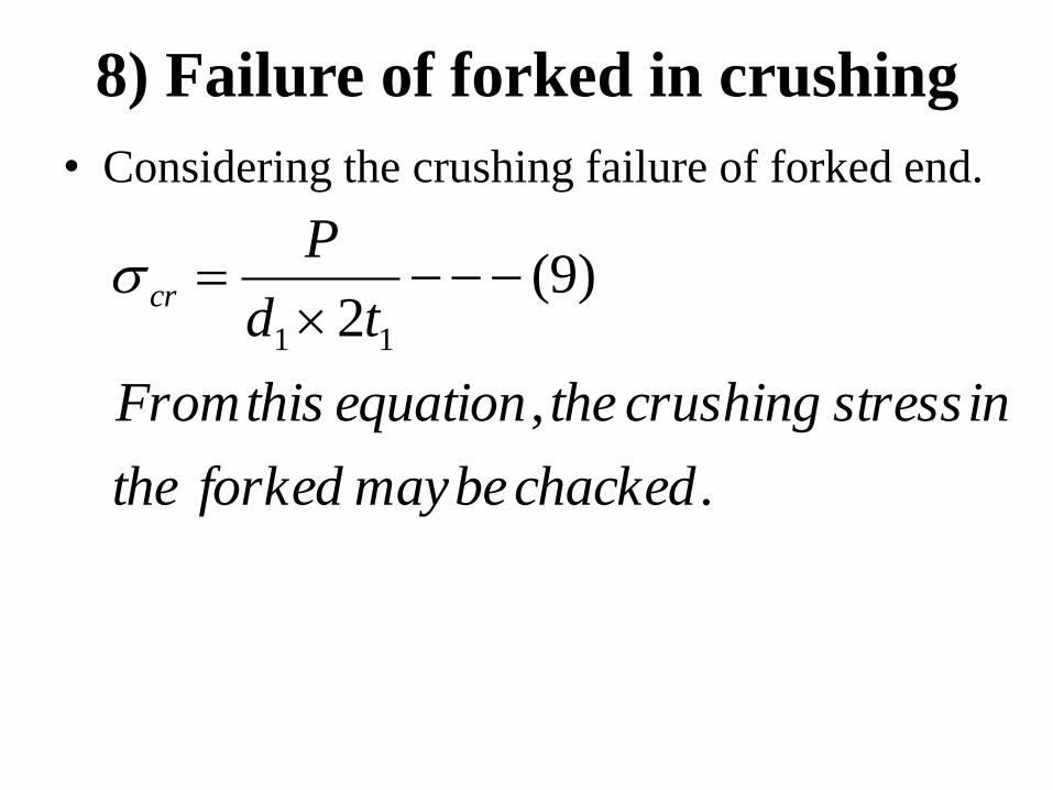
8) Failure of forked in crushing
• Considering the crushing failure of forked end.
.
,
)9(2 11
chackedbemayforkedthe
instresscrushingtheequationthisFrom
td
Pcr
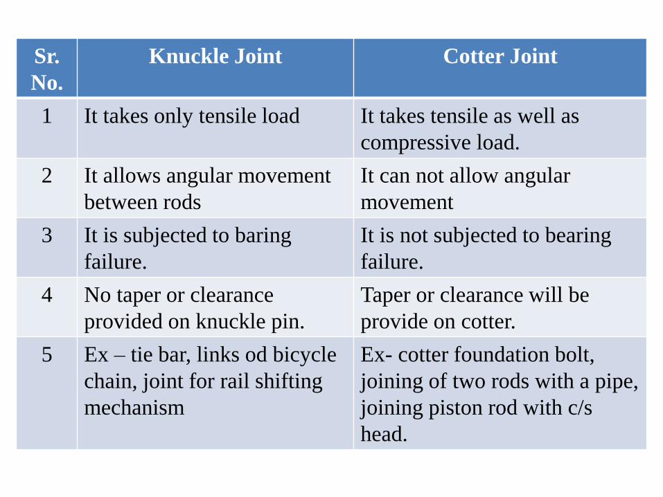
Sr.
No.
Knuckle Joint Cotter Joint
1 It takes only tensile load It takes tensile as well as
compressive load.
2 It allows angular movement
between rods
It can not allow angular
movement
3 It is subjected to baring
failure.
It is not subjected to bearing
failure.
4 No taper or clearance
provided on knuckle pin.
Taper or clearance will be
provide on cotter.
5 Ex – tie bar, links od bicycle
chain, joint for rail shifting
mechanism
Ex- cotter foundation bolt,
joining of two rods with a pipe,
joining piston rod with c/s
head.
Problems