design of mechanical presses driven by multi-servomotor · design of mechanical presses driven by...
TRANSCRIPT
Journal of Mechanical Science and Technology 25 (9) (2011) 2323~2334
www.springerlink.com/content/1738-494x DOI 10.1007/s12206-011-0603-9
Design of mechanical presses driven by multi-servomotor†
Yongjun Bai*, Feng Gao and Weizhong Guo State Key Laboratory of Mechanical System and Vibration, Shanghai Jiao Tong University, Shanghai, China
(Manuscript Received June 27, 2010; Revised March 13, 2011; Accepted June 1, 2011)
----------------------------------------------------------------------------------------------------------------------------------------------------------------------------------------------------------------------------------------------------------------------------------------------
Abstract This paper proposes a so-called multi-servomotor parallel driven scheme to construct high capacity mechanical presses. The design
method is based on the combination of dual screw actuation unit, parallel mechanism with kinematic redundancy (PMKR) and toggle mechanism with symmetric arrangement. Here, the dual screw actuation unit, which consists of two ball screws driven by two servomo-tors respectively, acts as a linear actuator. By connection with PMKR, several actuators are incorporated to generate large driving force to push the ram of press via toggle mechanism. To get more power from more linear actuation units, three kinds of 2-, 3-, 6-degree of free-dom (DoF) PMKRs with linear actuators are proposed. A 2-DoF PMKR example is studied, and its load capability and accuracy per-formance are illustrated. Finally, three schematics of 4-, 6- and 12- servomotor mechanical presses are presented. These schemes demon-strate the feasibility of the design method to develop high capacity mechanical presses driven by multi-servomotor.
Keywords: Mechanical presses; Dual screw actuation unit; Parallel mechanism with kinematic redundancy; Multi-servomotor driven ---------------------------------------------------------------------------------------------------------------------------------------------------------------------------------------------------------------------------------------------------------------------------------------------- 1. Introduction
For low cost and high productivity, stamping operations are widely used to manufacture products ranging from automotive panels to kitchen sinks. Different from a conventional me-chanical press, in a servo-driven mechanical press the servo-motors are directly attached to the press drive shaft and re-place the flywheel, clutch and main motor. Therefore, servo-mechanical presses have programmable stroke and velocity to fulfill various requirements [1-8]. Consequently, improved economic and increased energy efficiency can be achievable by employing servo presses.
On one hand, the direct-drive approach enables the flexibil-ity of the slide motion. On the other hand, absence of energy accumulation device, such as the flywheel of the mechanical presses or the accumulator of the hydraulic presses, also limits servomechanical press to a lower stamping capacity. The fur-ther development of servopress seems to be restricted by the power available from commercial servomotors. For the pur-pose of developing high capacity servopress, numerous press manufacturers have implemented many different approaches [9-13] such as high torque and low round servomotors, driving mechanism with force-multiplier effect and redundant actua-tion. Here, the redundant actuation means two or more servo-motors were used to drive a common ram of press. Currently,
the redundant actuation in servopresses is executed mainly through two ways. One way is that each servo motor inde-pendently works, while a complex control system coordinates servo motors motion to drive ram up or down in parallel to press bolster at all times. The other way is to have a gear on the drive shaft and build a housing that holds all servomotors with pinions to drive the same gear. Therefore, energy from each servo motor converges to the slide through this gear transmission system. Since not only the tight motion synchro-nization but also the load distribution among these different servomotors should be guaranteed by control system to avoid interference, one can see that the both methods increase con-trol cost and are difficult to maintain.
Considering that servomechanical presses provide energy on demand, this puts stress on a servomotor when the job needs large forming forces quickly. From kinematic point of view, most of the current driving mechanisms of servopresses are single DoF link mechanism whose driving torque comes solely from a servomotor. The regular solution to this problem is to use high capacity servomotors, but this incurs additional financial expense and technical challenge. Although two or more servomotors can be used to directly actuate the common ram (which has only one translational DoF) by synchronous control strategy, there still exists the risk of becoming over-constrained, which is caused by the actuation redundancy. If servomotors don’t run in harmony strictly at any time, the output motions from servomotors will interfere with each other, and even destroy the structure of the press. Due to these reasons, multiple servomotor actuation without causing over-
† This paper was recommended for publication in revised form by Associate EditorEung-Soo Shin
*Corresponding author. Tel.: +8602134206297, Fax.: +8602134206297 E-mail address: [email protected]
© KSME & Springer 2011
2324 Y. Bai et al. / Journal of Mechanical Science and Technology 25 (9) (2011) 2323~2334
constrained is a suitable approach to develop high capacity presses.
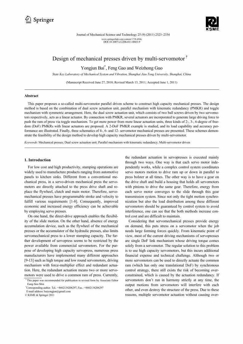
In view of the above conditions, we propose a design me-thod to construct a new type of mechanical presses driven by multiple servomotors. Overall, a dual screw actuation unit driven by two servomotors is described [14], which has been confirmed in a servo press prototype with 200 t tonnage being developed in our laboratory with the cooperation of a well-established press manufacturer, as shown in Fig. 1. The dual screw actuation unit acts as linear actuator. If two component screws have the same load capability, the dual screw actuation unit possesses twice the load capability as one screw. Next, three kinds of 2-, 3- and 6-DoF PMKR are proposed to avoid over-constraint caused by actuation redundancy. A 2-DoF parallel mechanism example is given to illustrate the load capability and accuracy performance. Finally, by combination of 2-, 3- and 6-DoF parallel mechanism, the dual screw actua-tion unit and the toggle mechanism with symmetric arrange-ment, three kinds of 4-, 6- and 12- servomotor driven me-chanical presses are presented, and their schematic illustra-tions are described. These schemes demonstrate the feasibility of the design method to develop high capacity mechanical presses driven by multi-servomotor.
2. The dual screw actuation unit
In precision and engineering applications, where motion is controlled by using computers, the conversion between rota-tional and translational motion is usually done by ball screw mechanism. The reciprocating ball screw transfers torque from motor into force to withstand high thrust loads along the shaft axis. Some of the most important features of the device are its positional accuracy, high mechanical efficiency and load carrying capability. These advantages make it suitable for high precision and high load machine tools. Since single ball screw can provide finite load capability, it is incompetent for heavy duty job. Consequently, a dual screws actuation unit is applied here.
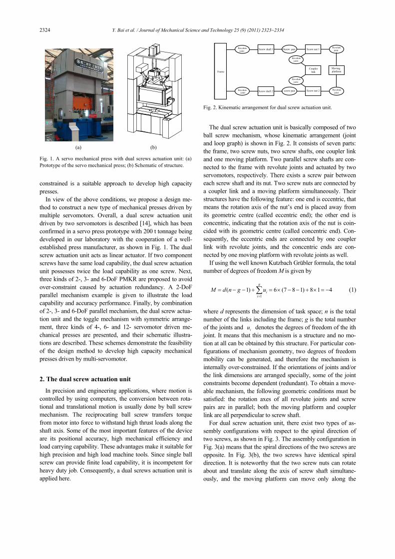
The dual screw actuation unit is basically composed of two ball screw mechanism, whose kinematic arrangement (joint and loop graph) is shown in Fig. 2. It consists of seven parts: the frame, two screw nuts, two screw shafts, one coupler link and one moving platform. Two parallel screw shafts are con-nected to the frame with revolute joints and actuated by two servomotors, respectively. There exists a screw pair between each screw shaft and its nut. Two screw nuts are connected by a coupler link and a moving platform simultaneously. Their structures have the following feature: one end is eccentric, that means the rotation axis of the nut’s end is placed away from its geometric centre (called eccentric end); the other end is concentric, indicating that the rotation axis of the nut is coin-cided with its geometric centre (called concentric end). Con-sequently, the eccentric ends are connected by one coupler link with revolute joints, and the concentric ends are con-nected by one moving platform with revolute joints as well.
If using the well known Kutzbach Grübler formula, the total number of degrees of freedom M is given by
1( 1) 6 (7 8 1) 8 1 4
g
ii
M d n g u=
= − − + = × − − + × = −∑
(1)
where d represents the dimension of task space; n is the total number of the links including the frame; g is the total number of the joints and iu denotes the degrees of freedom of the ith joint. It means that this mechanism is a structure and no mo-tion at all can be obtained by this structure. For particular con-figurations of mechanism geometry, two degrees of freedom mobility can be generated, and therefore the mechanism is internally over-constrained. If the orientations of joints and/or the link dimensions are arranged specially, some of the joint constraints become dependent (redundant). To obtain a move-able mechanism, the following geometric conditions must be satisfied: the rotation axes of all revolute joints and screw pairs are in parallel; both the moving platform and coupler link are all perpendicular to screw shaft.
For dual screw actuation unit, there exist two types of as-sembly configurations with respect to the spiral direction of two screws, as shown in Fig. 3. The assembly configuration in Fig. 3(a) means that the spiral directions of the two screws are opposite. In Fig. 3(b), the two screws have identical spiral direction. It is noteworthy that the two screw nuts can rotate about and translate along the axis of screw shaft simultane-ously, and the moving platform can move only along the
(a) (b) Fig. 1. A servo mechanical press with dual screws actuation unit: (a)Prototype of the servo mechanical press; (b) Schematic of structure.
Frame
Revolute joint Screw shaft 2 screw pair Screw nut 2
Coupler link
Revolute joint
Screw shaft 1 Screw pair Screw nut 1
Revolute joint
Revolute joint
Moving platform
Revolute joint
Revolute joint
Fig. 2. Kinematic arrangement for dual screw actuation unit.
Y. Bai et al. / Journal of Mechanical Science and Technology 25 (9) (2011) 2323~2334 2325
screw shaft together with two nuts. Furthermore, if the structure dimensions are arranged spe-
cially, i.e., two eccentric distances of the eccentric end are the same and the length of coupler link is equal to the distance between the two screw shafts, we can get a 2-DOF dual screw transmission mechanism with special kinematic and load dis-tribution feature. In this design, the dual screw actuation unit with assembly configuration shown in Fig. 3(a) is adopted, whose kinematics and load distribution are briefly described in Appendix A.
3. The parallel mechanism with kinematic redun-
dancy
Parallel mechanism is a closed-loop kinematic chain me-chanism whose moving platform is linked to the base by inde-pendent kinematic chains. Parallel mechanisms have been utilized in many industrial applications, where high load car-rying capability (flight simulator, automobile simulator, tank simulator, earthquake simulator and so on), good kinematic and dynamic performance (parallel machine tools, Delta robot for very fast pick-and-place tasks, force and torque sensors, legs of walking machines) and precise positioning (micro-manipulators, manipulator for ophthalmic surgery operation). However, the parallel manipulators have also some drawbacks, such as limited workspace, more constraining singularity loci or a high coupling of kinematics and dynamics [15].
To overcome the aforementioned disadvantages of parallel mechanisms, much research on redundant parallel mechanism has been conducted [16-19]. There are many advantages for the redundant parallel manipulator, such as avoiding kine-matic singularities, increasing workspace, improving dexterity, and enlarging load capability. Redundancy in parallel manipu-lators can be divided into two different types: actuation redun-
dancy and kinematic redundancy. If the number of actuators of a mechanism is greater than its mobility, the mechanism has actuation redundancy. On the other hand, if the mobility of the mechanism is greater than the degree of freedom required performing a task, the mechanism is kinematically redundant. It is noted that actuation redundancy introduces more actuators than the minimum needed for controlling the mechanism, and then results in the internal force control problem. Since the errors in internal force control are harmful to links, the use of mere position control is no longer possible. In contrast, kine-matic redundancy has more controlled actuators in the execu-tion of a given task, so it is possible to adjust the configuration of a mechanism without changing the position and orientation of its end-effector. The choice of configuration may be based on different criteria, such as minimum energy, minimum con-dition number, minimum distance or minimum travel time. Here, the design criterion is set as the maximum load capabil-ity. For these reasons, in this design, kinematic redundancy other than actuation redundancy is used as a solution to achieve large load capability and avoid internal force conflict.
Kinematic redundancy is originally introduced to serial ma-nipulator and gets extensive applications. For parallel mecha-nisms, there are a few researches dealing with the issue [20-22]. In general, the kinematic redundancy can be implemented by adding extra active joints and links to limbs. For servo-presses, the stamping task is the reciprocating motion of the punch ram with only one translational DoF. In case of using non-redundant mechanism, the mobility of the mechanism is one, which means that only one actuator drives the single DoF mechanism. However, for kinematically redundant mecha-nism, the redundant DoFs introduce more actuators to be used. To get more load capacity from more actuators, some kinds of 2-, 3-, 6-DoF PMKR are proposed here.
3.1 Planar 2-DoF PMKR
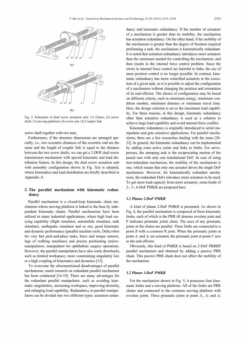
A kind of planar 2-DoF PMKR is presented. As shown in Fig. 4, the parallel mechanism is composed of three kinematic limbs, each of which is the PRR (R denotes revolute joint and P indicates prismatic joint) chain. The axes of any prismatic joints in the chains are parallel. Three limbs are connected to a point B with a common R joint. When the prismatic joints at point A1 and A2 are actuated, the prismatic joint at point C acts as the end-effector.
Obviously, this kind of PMKR is based on 2-DoF PRRRP parallel mechanism and obtained by adding a passive PRR chain. This passive PRR chain does not affect the mobility of the mechanism.
3.2 Planar 3-DoF PMKR
For the mechanism shown in Fig. 5, it possesses four kine-matic limbs and a moving platform. All of the limbs are PRR chains and connected to the common moving platform with revolute joints. Three prismatic joints at point A1, A2 and A3
12345 (a)
12345 (b)
Fig. 3. Schematic of dual screw actuation unit: (1) Frame; (2) screw shaft; (3) moving platform; (4) screw nut; (5) Coupler link.
2326 Y. Bai et al. / Journal of Mechanical Science and Technology 25 (9) (2011) 2323~2334
are driven by linear actuators, respectively. The prismatic joint at point D is the end-effector. Although the mobility of mechanism is three, the output is just limited to one transla-tional DoF. Therefore, this kind of mechanism is also kine-matically redundant. It is clear that this kind of parallel mechanism is a combination of a 3-DoF fully-parallel mecha-nism with 3- PRR structure and a passive PRR chain that couldn’t constrain the motion of the moving platform.
3.3 Spatial 6-DoF PMKR
Fig. 6 shows a kind of spatial 6-DoF PMKR. Seven PSS (S denotes spherical joints) limbs are connected to the common moving platform with spherical joints. When six prismatic joints at points A1, A2, A3, A4, A5, and A6 are actuated, the mov-ing platform can execute movement with six DoFs. It can be seen that the active six PSS limbs and moving platform con-struct a 6-PSS fully-parallel mechanism with six DoFs, and the last PSS limb with 6-DoF is passive and imposes no con-straint on the motion of the moving platform. The motion of prismatic joint D in the passive PSS limb is the output of the mechanism.
By observing the above parallel mechanisms shown in Figs. 4-6, we can conclude some main common configuration char-acteristics. First, all active kinematic limbs are identical and arranged in a symmetric pattern. This type of arrangement is suitable for dividing the applied load equally among limbs. Next, there exists a prismatic joint driven by linear actuator in each of active limbs. The choice of linear actuator as input device is based on the novel driving concept of the dual screw
actuation unit. The application of dual screw actuation unit can decrease the requirement of high capacity servomotors and exceed the limits of the single ball screw’s strength and durability. Finally, the translational axes of prismatic joint including inputs and output are all parallel. Such arrangement is for the purpose of possessing high load carrying capability without speed losses.
4. Performance study example
From the presentation of the three kinds of PMKR, we chose the planar 2-DoF PMKR shown in Fig. 4 to study. Since it has relatively simple structure and lesser design parameters, such performance characteristics as load capability and accu-racy can be illustrated more explicitly. This helps us gain physical insight into the advantages of the PMKR. The study method is also available for 3-, 6-DoF PMKR.
4.1 Kinematic analysis
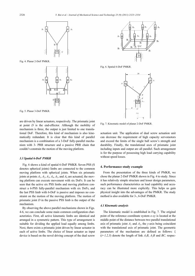
The kinematic model is established in Fig. 7. The original point of the reference coordinate system o-xy is located at the middle point of the distance between two parallel translational axis of prismatic joint A1 and A2, the y-axis being coincident with the translational axis of prismatic joint. The geometric parameters of the mechanism are defined as follows: li (i=1,2,3) denote the length of link A1B, A2B and BC, respec-
A1
D
A4
A3
B5
A5A6
B1B2
B3
B4B6
A2
C
Fig. 6. Spatial 6-DoF PMKR.
x
y
A1
A2
C
B
o
2R
R
l1 l2
l3
θ
Fig. 7. Kinematic model of planar 2-DoF PMKR.
A1 A2
C
B
Fig. 4. Planar 2-DoF PMKR.
A1 A3A2
B1 B2 B3
C
D
Fig. 5. Planar 3-DoF PMKR.

Y. Bai et al. / Journal of Mechanical Science and Technology 25 (9) (2011) 2323~2334 2327
tively, 2R stands for the distance between two translational axis of prismatic joint A1 and A2. To make the mechanism be assembled and work freely, there should be l1>R and l2>R. Moreover, considering the symmetric arrangement, lengths of link A1B and A2B should be the same, i.e., l1= l2.
The positions of points A1, A2, B and C with respect to the coordinate system o-xy are denoted as the following vector:
1 1
2 2
OA [- , ]
OA [ , ]
OB [ , ]
OC [0, ]
TA
TA
TB B
TC
R y
R y
x y
y
=
=
=
=
, (2)
where yA1 and yA2 are the input variables, yC is the output vari-able of the parallel mechanism.
The link lengths li (i=1,2,3) can be expressed as:
1 1 1
2 2 2
3
A B OB OA
A B OB OA
BC OC OB
l
l
l
= =
= =
= =
-
-
-
. (3)
That is
( ) ( )2 2 21 1B B Ax R y y l+ + − = , (4)
( ) ( )2 2 22 2B B Ax R y y l− + − = , (5)
( )22 23B B Cx y y l+ − = . (6)
Obviously, for a given set of inputs yA1 and yA2 , the output
yC can be directly computed from Eqs. (4)-(6). That means there are certain solutions for the direct kinematics problem. However, for a given position of output yC, the required actu-ated inputs can’t be determined uniquely and have infinite possible solutions. Therefore, with kinematic redundancy, the solution to the inverse kinematics problem no longer has a unique solution. This infinity of possible solutions allows the configuration of mechanism to be optimized.
By differentiating Eqs. (4)-(6) with respect to time, the ve-locity equations can be obtained as
1
1 22
B A
B A
x yy y⎡ ⎤ ⎡ ⎤
=⎢ ⎥ ⎢ ⎥⎣ ⎦ ⎣ ⎦
J J , (7)
( ) 3B
B C CB
xy y y
y⎡ ⎤
− = ⎢ ⎥⎣ ⎦
J .
(8)
where J1 and J2 are 2×2 matrices, J3 is 1×2 matrices that can be expressed as
1
2
B B A
B B A
x R y yx R y y
+ −⎡ ⎤= ⎢ ⎥− −⎣ ⎦
1J , (9)
1
2
00
B A
B A
y yy y
−⎡ ⎤= ⎢ ⎥−⎣ ⎦
2J , (10)
[ ]B B Cx y y= −3J . (11)
If matrix J1 is non-singular, and yB≠yC , combining Eqs. (7)
and (8) yields
1
2
A
A
yy⎡ ⎤⎢ ⎥⎣ ⎦
Cy = J . (12)
where J is the Jacobian matrix which maps the velocity vector of output into the velocity vector of input.
( ) [ ]11 12J JB C
1y - y
-13 1 2J = J J J = , (13)
( )( ) ( )( )( )( ) ( )( ) ( )( )
2 1 111
2 1
B B A B A B B A B C
B C B B A B B A
x y y y y x R y y y yJ
y y x R y y x R y y− − − − − −
=− ⎡ + − − − − ⎤⎣ ⎦
,
(14) ( )( ) ( )( )( )
( ) ( )( ) ( )( )2 1 2
122 1
B B A B A B B A B C
B C B B A B B A
x y y y y x R y y y yJ
y y x R y y x R y y− − − + + − −
=− ⎡ + − − − − ⎤⎣ ⎦
.
(15) Since Eqs. (4)-(6) can be rewritten as
( )221 1B A By y l x R− = ± − + , (16)
( )222 2B A By y l x R− = ± − − , (17)
2 23B C By y l x− = ± − . (18)
For the configuration shown in Fig. 6 that the sign “±” in Eqs. (16) and (17) is both “-”, and the sign “±” in Eq. (18) is “+”, then the J11 and J12 in Jacobian matrix can be rewritten as
( )( ) ( )( ) ( ) ( )( )( )( ) ( )( ) ( ) ( )( )
2 2 22 2 2 2 22 1 1 3
112 22 2 2 2
3 2 1
B B B B B B
B B B B B
x l x R l x R x R l x R l xJ
l x x R l x R x R l x R
− − − − − + − − − − + −=
⎡ ⎤− + − − − − − − − +⎢ ⎥⎣ ⎦
(19) ( )( ) ( )( ) ( ) ( )( )( )
( ) ( )( ) ( ) ( )( )2 2 22 2 2 2 2
2 1 2 3
122 22 2 2 2
3 2 1
.B B B B B B
B B B B B
x l x R l x R x R l x R l xJ
l x x R l x R x R l x R
− − − − − − + + + − − − −=
⎡ ⎤− + − − − − − − − +⎢ ⎥⎣ ⎦
(20)
From Eqs. (19) and (20), we can see that the Jacobian matrix is independent of y.
4.2 Load distribution
In the 2-DoF parallel mechanism, the load acting on the end-effector is distributed between two independent kinematic chains with actuator. To achieve the most load capability of the mechanism, it is necessary to investigate the relationship between the driving force requirements of each actuator and the configuration of the mechanism.

2328 Y. Bai et al. / Journal of Mechanical Science and Technology 25 (9) (2011) 2323~2334
According to the principle of virtual work, the virtual work of the external force applied to the system must be zero, so
1 1 2 2 3 3 0F q F q F qδ δ δ+ + = (21)
where F1 and δq1 are the driving forces that act on prismatic joint A1 and its corresponding virtual displacement, F2 and δq2 are the driving forces that act on prismatic joint A2 and its corresponding virtual displacement, F3 and δq3 are the applied forces that act on prismatic joint C and its corresponding vir-tual displacement.
The relationship between the virtual displacement δq1, δq2 and δq3 is determined by the Jacobian matrix and expressed as
1
32
qδ
δδ⎡ ⎤⎢ ⎥⎣ ⎦
= J . (22)
Substituting Eq. (22) into Eq. (21) yields
( ) ( )1 1 3 11 2 2 3 12 0.q F F J q F F Jδ δ+ + + = (23)
Since Eq. (23) is always valid for any arbitrary virtual dis-
placements δq1 and δq2,it must follow that
1 3 11F F J= − , (24)
2 3 12F F J= − . (25) Referring to Eqs. (19) and (20), besides the applied force F3 ,
it is clear that the values of driving force depend on the posi-tion of the point B along the x-axis only (if the structure di-mension is specified). That means the driving force will keep constant if xB does not change whatever the value of yB is. In addition, there are two special load distribution cases needed to be considered. The first case is F1=0. According to Eqs. (14), (15), (24) and (25), there is
( ) ( )( ) ( )2 1 0B B A B B C B Ax y y x R y y y y⎡ − − − − ⎤ − =⎣ ⎦ , (26)
F2=-F3. (27)
The geometric meaning of the first case is link A2B and BC are collinear, as shown in Fig. 8(a), or link A1B is parallel to the x-axis, as shown in Fig. 8(b). In this case, the external load is wholly supported by the prismatic joint A2.
The second case is F2=0. Similarly, based on Eqs. (14), (15), (24) and (25), one can get
( ) ( )( ) ( )1 2 0B B A B B C B Ax y y x R y y y y⎡ − − + − ⎤ − =⎣ ⎦ , (28)
F1=-F3. (29)
For this case, the geometric meaning is link A1B and BC are collinear, as shown in Fig. 9(a), or link A2B is parallel to the x-axis, as shown in Fig. 9(b). Meanwhile, the external load is wholly supported by the prismatic joint A1.
It is noted that the examples shown in Fig. 8(b) and 9(b) should not happen when l1>R+ l3 and l2>R+ l3.
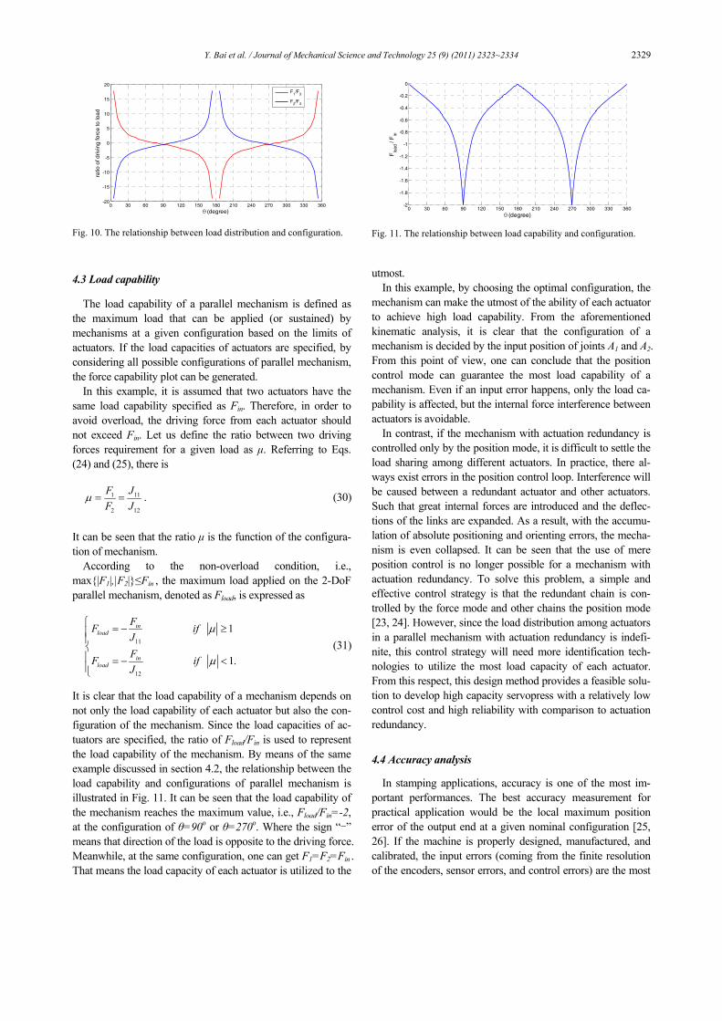
As an example, a mechanism with the structure parameters specified as l1=l2=2,l3=0.2,R=0.5 is considered to illus-trate the load distribution. As mentioned above, the load dis-tribution is evaluated based on the Jacobian matrix which is independent of y. Therefore, we can just consider the issue along the x-axis. The corresponding configuration of the mechanism can be represented by xB which is expressed by the angle θ measured with respect to the positive x-axis in Fig. 6, that is, xB=l3cosθ. Here, we use the ratio of F1/F3 and F2/F3 to describe the requirement of driving force for a given load F3. Through Eqs. (19), (20), (24) and (25), the relationship be-tween the driving force requirements for a given load and configuration of mechanism is obtained and illustrated in Fig. 10. One can see that the requirement of driving force varies dramatically with respect to the configuration. At the configu-ration of θ=90o or θ=270o, the driving forces are equal to each other, i.e., F1/F3 = F2/F3 =-0.5, where the sign “-” means op-posite direction of the load. This means the external load is divided equally between two actuators. But at some configura-tion, the requirement of driving force from one actuator is far more than the applied load. For example, when θ=0o or θ=180o, the required driving forces are infinite. These con-figurations should be avoided in practice.
(a) (b) Fig. 8. Examples of the geometrical meaning in the case of F1=0.
(a) (b) Fig. 9. Examples of the geometrical meaning in the case of F2=0.
Y. Bai et al. / Journal of Mechanical Science and Technology 25 (9) (2011) 2323~2334 2329
4.3 Load capability
The load capability of a parallel mechanism is defined as the maximum load that can be applied (or sustained) by mechanisms at a given configuration based on the limits of actuators. If the load capacities of actuators are specified, by considering all possible configurations of parallel mechanism, the force capability plot can be generated.
In this example, it is assumed that two actuators have the same load capability specified as Fin. Therefore, in order to avoid overload, the driving force from each actuator should not exceed Fin. Let us define the ratio between two driving forces requirement for a given load as μ. Referring to Eqs. (24) and (25), there is
1 11
2 12
F JF J
μ = = . (30)
It can be seen that the ratio μ is the function of the configura-tion of mechanism.
According to the non-overload condition, i.e., max{|F1|,|F2|}≤Fin , the maximum load applied on the 2-DoF parallel mechanism, denoted as Fload, is expressed as
11
12
1
1.
inload
inload
FF ifJFF ifJ
μ
μ
⎧ = − ≥⎪⎪⎨⎪ = − <⎪⎩
(31)
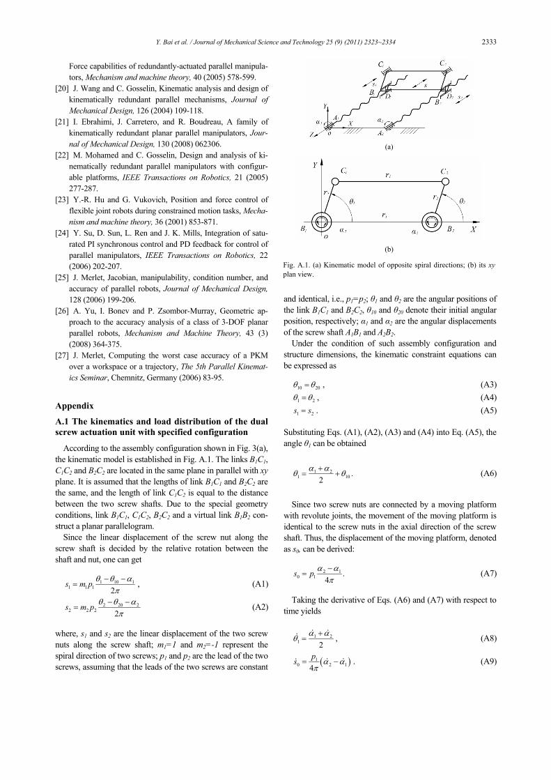
It is clear that the load capability of a mechanism depends on not only the load capability of each actuator but also the con-figuration of the mechanism. Since the load capacities of ac-tuators are specified, the ratio of Fload/Fin is used to represent the load capability of the mechanism. By means of the same example discussed in section 4.2, the relationship between the load capability and configurations of parallel mechanism is illustrated in Fig. 11. It can be seen that the load capability of the mechanism reaches the maximum value, i.e., Fload/Fin=-2, at the configuration of θ=90o or θ=270o. Where the sign “-” means that direction of the load is opposite to the driving force. Meanwhile, at the same configuration, one can get F1=F2=Fin . That means the load capacity of each actuator is utilized to the
utmost. In this example, by choosing the optimal configuration, the
mechanism can make the utmost of the ability of each actuator to achieve high load capability. From the aforementioned kinematic analysis, it is clear that the configuration of a mechanism is decided by the input position of joints A1 and A2. From this point of view, one can conclude that the position control mode can guarantee the most load capability of a mechanism. Even if an input error happens, only the load ca-pability is affected, but the internal force interference between actuators is avoidable.
In contrast, if the mechanism with actuation redundancy is controlled only by the position mode, it is difficult to settle the load sharing among different actuators. In practice, there al-ways exist errors in the position control loop. Interference will be caused between a redundant actuator and other actuators. Such that great internal forces are introduced and the deflec-tions of the links are expanded. As a result, with the accumu-lation of absolute positioning and orienting errors, the mecha-nism is even collapsed. It can be seen that the use of mere position control is no longer possible for a mechanism with actuation redundancy. To solve this problem, a simple and effective control strategy is that the redundant chain is con-trolled by the force mode and other chains the position mode [23, 24]. However, since the load distribution among actuators in a parallel mechanism with actuation redundancy is indefi-nite, this control strategy will need more identification tech-nologies to utilize the most load capacity of each actuator. From this respect, this design method provides a feasible solu-tion to develop high capacity servopress with a relatively low control cost and high reliability with comparison to actuation redundancy.
4.4 Accuracy analysis
In stamping applications, accuracy is one of the most im-portant performances. The best accuracy measurement for practical application would be the local maximum position error of the output end at a given nominal configuration [25, 26]. If the machine is properly designed, manufactured, and calibrated, the input errors (coming from the finite resolution of the encoders, sensor errors, and control errors) are the most
0 30 60 90 120 150 180 210 240 270 300 330 360-20
-15
-10
-5
0
5
10
15
20
(degree)θ
ratio
of d
rivin
g fo
rce
to lo
ad
F1/F
3
F2/F
3
Fig. 10. The relationship between load distribution and configuration.
0 30 60 90 120 150 180 210 240 270 300 330 360-2
-1.8
-1.6
-1.4
-1.2
-1
-0.8
-0.6
-0.4
-0.2
0
(degree)θ
Flo
ad /
Fin
Fig. 11. The relationship between load capability and configuration.

2330 Y. Bai et al. / Journal of Mechanical Science and Technology 25 (9) (2011) 2323~2334
significant source of output position errors [27]. Here, we address the problem of computing the accuracy in the pres-ence of input errors only. Given the input errors, the output position error can be calculated from the direct and inverse kinematics at a given nominal configuration.
In the planar 2-DoF PMKR, let yA1, yA2 and yC denote the nominal input position of the prismatic joints A1, A2, and the corresponding nominal output position of the prismatic joint C, respectively. In addition, the nominal configuration is indi-cated by the angular position θ of the link BC. It is supposed that the same actuators were used. As a result, the maximum input errors are identical and denoted as ±ε. As shown in Fig. 12, the actual positions of prismatic joints A1 and A2, i.e., yA1’ and yA2’, are located somewhere in the ranges [yA1-ε, yA1+ε] and [yA2-ε, yA2+ε], respectively. The hatched area is the maxi-mal workspace for the joint B with regard to the actual input ranges of joints A1 and A2. The four vertices Pi (i=1, 2, 3, 4) correspond to the combinations of limit of input: (yA1+ε, yA2+ε), (yA1+ε, yA2-ε), (yA1-ε, yA2-ε), and (yA1-ε, yA2+ε), respec-tively. Referring to Eq. (18), the actual position of joint C can be obtained by sweeping xB and yB in the hatched area.
For demonstrating the relationship between the output posi-tion error and nominal configuration, the same example dis-cussed previously is used, in which ε=0.00001 is considered. To evaluate the accuracy performance, the output position error of prismatic joint C is defined as ΔyC/ε= (yC’-yC)/ε, where yC’ denotes the actual position. Similarly, the input errors are defined as ΔyA1/ε=(yA1’-yA1)/ε and ΔyA2/ε=(yA2’-yA2)/ε.
Fig. 13 illustrates the effects of the nominal configurations on distribution of output position error with respect to input position error (considering the symmetric arrangement of mechanism, some configurations are chosen in the range [0o, 90o]). It shows that the output position errors when ΔyA1/ε=±1 and ΔyA2/ε= ∓ 1 (corresponding to vertex P2 and P4, respec-tively) vary drastically with the configuration. But when ΔyA1/ε=±1 and ΔyA2/ε= ±1 (corresponding to vertex P1 and P3, respectively), the output position errors are independent of the configuration. This can be explained by geometric analysis in Fig. 12, where the dotted lines and dash lines denote the con-
figurations with maximum input errors ε and –ε, respectively. Due to the parallelogram constraint, one can deduce that line P1P3 is always parallel to y-axis and |P1B|=|P2B|=ε. Conse-quently, the output position error ΔyC/ε is equal to 1 and -1 (corresponding to vertex P1 and P3, respectively) at any con-figuration.
The maximum output position error (defined as max{|ΔyC/ε|}) can be checked for each nominal configuration, and the results are shown in Fig. 14. It can be seen that when angular position θ is near 90o or 270o the maximum output errors are equal to the maximum input error. If the configura-tion is far away from θ=90o and θ=270o, the maximum output error is much larger than the maximum input error.
Fig. 12. Schematic of errors analysis.
-1-0.5
00.5
1
-1
-0.5
0
0.5
1-30
-20
-10
0
10
20
30
Δ yA1
/ ε Δ yA2
/ ε
Δ y
C / ε
(a) θ=10o
-1-0.5
00.5
1
-1-0.5
00.5
1-10
-5
0
5
10
Δ yA1
/ ε Δ yA2
/ ε
Δ y
C / ε
(b) θ=300
(c) θ=600
-1-0.5
00.5
1
-1-0.5
00.5
1-1.5
-1
-0.5
0
0.5
1
1.5
Δ yA1
/ ε Δ yA2
/ ε
Δ y
C / ε
(d) θ=900
Fig. 13. Effects of the configurations on distribution of output position error with respect to input position error.

Y. Bai et al. / Journal of Mechanical Science and Technology 25 (9) (2011) 2323~2334 2331
5. The schemes of multi-servomotor driven mechani-cal presses
Based on the PMKR and the dual screw actuation unit, three kinds of multi-servomotor driven parallel actuation mechanisms can be constructed. In addition, considering the fact that the stamping work only requires a large forming force during a little proportion of stroke near the end, a force ampli-fication mechanism such as toggle mechanism is introduced into the design. For toggle mechanism, a small input force can generate an extremely large output force, whose mechanical advantage is dependent on the position of output slide. At a specified position, the slider can produce an extremely large power to press workpiece. For this reason, a toggle mecha-nism with symmetric arrangement is utilized to build a high capacity servopress. A symmetric arrangement is available for counteracting lateral forces on the guide from the ram and providing perfect ram parallelism. With a combination of parallel actuation mechanisms (consisting of a parallel mecha-nism and several dual screw actuation units) and toggle mechanism with symmetric arrangement, three kinds of multi-servomotor driven mechanical presses are presented.
Fig. 15 describes the schematic of a 4-servomotor driven mechanical press. Its operation principle is described as fol-lows. Two servomotors (1) are directly connected to a dual screw actuation unit, (2) whereby the rotating motions from servomotors are transferred into reciprocating motion of the component moving platform along the guide (3). In this way, four servomotors divided into two groups drive two dual screw actuation units, respectively. When servomotors run, the two component moving platforms of dual screw actuation unit push the corresponding driving link (4) to move the common slide (6) up and down along the guide (5) vertically via coupler link (9). Next, the slide (6) operates the toggle mechanism with symmetric arrangement (8) to drive the ram (7) performing the stamping work. Consequently, the power from four servomotors is incorporated to generate high form-ing capacity.
As shown in Figs. 16 and 17, the schematics of 6- and 12- servomotor driven mechanical presses are illustrated. Their operation principles are similar to the 4-servomotor driven mechanical press. Compared with 4-servomotor driven me-chanical presses shown in Fig. 15, besides the quantity of ser-vomotors, dual screw actuation units and driving links, the
differences is that there is such an extra moving platform, i.e., part (10) in Figs. 16 and 17, between driving links and coupler link.
These schemes demonstrate the feasibility of the design method to develop high capacity mechanical presses driven by multi-servomotor.
6. Conclusions
This paper presents a design method to develop high capac-ity servomechanical presses. The main contributions of this paper are as follows:
0 30 60 90 120 150 180 210 240 270 300 330 3600 1
5
10
15
20
25
30
(degree)θ
max
{|Δ
y C / ε |
}
Fig. 14. Maximum output position errors for different configurations.
9
4
8
5
7
1
2
10
6
3
(a) 3D model (b) Front view Fig. 15. Schematic of 4-servomotor driven mechanical press: (1) Ser-vomotor; (2) dual screw actuation unit; (3) guide for dual screw actua-tion unit; (4) driving link; (5) guide for slide; (6) slide; (7) ram; (8) toggle mechanism with symmetric arrangement; (9) coupler link; (10) frame.
8
7
2
6
3
5
11
10
9
4
1
(a) 3D model (b) Front view Fig. 16. Schematic of 6-servomotor driven mechanical press: (1) Ser-vomotor; (2) dual screw actuation unit; (3) guide for dual screw actua-tion unit; (4) driving link; (5) guide for slide; (6) slide; (7) ram; (8) toggle mechanism with symmetric arrangement; (9) coupler link; (10) moving platform; (11) frame.

2332 Y. Bai et al. / Journal of Mechanical Science and Technology 25 (9) (2011) 2323~2334
(1) A dual screw actuation unit driven by two servomotors is put forward to act as linear actuator. Under specified con-figuration, it possesses twice the load capability as one single screw mechanism in spite of the input motions of the servo-motors;
(2) To get more load capability from more linear actuators, some kinds of 2-, 3-, 6-DoF PMKR are proposed here. Com-pared with actuation redundancy, kinematic redundancy per-mits input error and avoids internal force conflict caused by over-constraint;
(3) An example of 2-DoF PMKR is studied. It proves that at certain configuration (for this example, that is θ=90o or θ=270o), the PMKR can make the utmost load capacity of each actuator to achieve high load capability and occupy the same accuracy as an actuator.
(4) With a combination of 2-, 3-, 6-DoF PMKR, dual screw actuation unit and a symmetric toggle mechanism, three schematics of 4-, 6- and 12- servomotor driven mechanical presses are illustrated.
Acknowledgment
This work was supported by the National Natural Science Foundation of China (NSFC Grant No. 50875161), and par-tially by the National Hi-Tech Research and Development Program of China (863 Program, Grant No. 2008AA04Z112).
References
[1] A. Osborn and S. Paul, Servo-press technology: Drive de-sign and performance, MetalForming, 42 (2008) 18-23.
[2] S. Yossifon, D. Messerly, E. Kropp, R. Shivpuri and T. Altan, A servo motor driven multi-action press for sheet
metal forming, International Journal of Machine Tools and Manufacture, 31 (1991) 345-359.
[3] S. Yossifon and R. Shivpuri, Analysis and comparison of selected rotary linkage drives for mechanical presses, Inter-national Journal of Machine Tools and Manufacture, 33 (1993) 175-192.
[4] S. Yossifon and R. Shivpuri, Optimization of a double knuckle linkage drive with contrast mechanical advantage for mechanical presses, International Journal of Machine Tools and Manufacture, 33 (1993) 193-208.
[5] S. Yossifon and R. Shivpuri, Design considerations for the electric servomotor driven 30 ton double knuckle press for precision forming, International Journal of Machine Tools and Manufacture, 33 (1993) 209-22.
[6] H. Yan and W. Chen, A variable input speed approach for improving the output motion characteristics of Watt-type presses, International Journal of Machine Tools and Manu-facture, 40 (2000) 675-690.
[7] R. Du and W. Guo, The design of a new metal forming press with controllable mechanism, Journal of Mechanical Design, 125 (2003) 582-592.
[8] W. Guo, K. He, K. Yeung, and R. Du, A new type of con-trollable mechanical press: motion control and experiment validation, Journal of Manufacturing Science and Engineer-ing, 127 (2005) 731-742.
[9] J. Lansowski, Sizing up servo presses: A look at tonnage and energy, Stamping Journal, 4 (2004) 12-14.
[10] T. Altan, Servo press forming applications part II: Drive systems, Stamping Journal, 4 (2007) 12.
[11] D. Boerger, Servo driven mechanical presses, AIDA-TECH, AIDA Dayton Technologies Corporation, 6 (2003).
[12] T. Heston, The science behind the servo press/Servomotor-driven mechanical press spurs a new way of thinking about forming metal, The fabricator, 38 (2008).
[13] K. Miyoshi, Current trends in free motion presses, Proc. 3rd JSTP International Seminar on Precision Forging, Na-goya, Japan (2004) 69-74.
[14] Y. Zhao, F. Gao, W. Li, W. Liu and X. Zhao, Development of 6-dof parallel seismic simulator with novel redundant ac-tuation, Mechatronics, 19 (2009) 422-427.
[15] F. Gao, W. Li, X. Zhao, Z. Jin, and H. Zhao, New kine-matic structures for 2-, 3-, 4-, and 5-DOF parallel manipula-tor designs, Mechanism and Machine Theory, 37 (2002) 1395-1411.
[16] J. Merlet, Redundant parallel manipulators, Laboratory Robotics and Automation, 8 (1996) 17-24.
[17] K. Zanganeh and J. Angeles, Mobility and position analy-ses of a novel redundant parallel manipulator, 1994 IEEE In-ternational Conference on Robotics and Automation (1994) 3049-3054.
[18] H. Cheng, G. Liu, Y. Yiu , Z. Xiong and Z. Li, Advantages and dynamics of parallel manipulators with redundant actua-tion, Proceedings of the 2001 IEEE/RSJ International Con-ference on Intelligent Robots and Systems (2001) 171-176.
[19] S. Nokleby, R. Fisher, R. Podhorodeski and F. Firmani,
8
7
2
6
3
5
11
10
94
1
(a) 3D model (b) Front view Fig. 17. Schematic of 12-servomotor driven mechanical press: (1) Servomotor; (2) dual screw actuation unit; (3) guide for dual screwactuation unit; (4) driving link; (5) guide for slide; (6) slide; (7) ram;(8) toggle mechanism with symmetric arrangement; (9) coupler link;(10) moving platform; (11) frame.
Y. Bai et al. / Journal of Mechanical Science and Technology 25 (9) (2011) 2323~2334 2333
Force capabilities of redundantly-actuated parallel manipula- tors, Mechanism and machine theory, 40 (2005) 578-599.
[20] J. Wang and C. Gosselin, Kinematic analysis and design of kinematically redundant parallel mechanisms, Journal of Mechanical Design, 126 (2004) 109-118.
[21] I. Ebrahimi, J. Carretero, and R. Boudreau, A family of kinematically redundant planar parallel manipulators, Jour-nal of Mechanical Design, 130 (2008) 062306.
[22] M. Mohamed and C. Gosselin, Design and analysis of ki-nematically redundant parallel manipulators with configur-able platforms, IEEE Transactions on Robotics, 21 (2005) 277-287.
[23] Y.-R. Hu and G. Vukovich, Position and force control of flexible joint robots during constrained motion tasks, Mecha-nism and machine theory, 36 (2001) 853-871.
[24] Y. Su, D. Sun, L. Ren and J. K. Mills, Integration of satu-rated PI synchronous control and PD feedback for control of parallel manipulators, IEEE Transactions on Robotics, 22 (2006) 202-207.
[25] J. Merlet, Jacobian, manipulability, condition number, and accuracy of parallel robots, Journal of Mechanical Design, 128 (2006) 199-206.
[26] A. Yu, I. Bonev and P. Zsombor-Murray, Geometric ap-proach to the accuracy analysis of a class of 3-DOF planar parallel robots, Mechanism and Machine Theory, 43 (3) (2008) 364-375.
[27] J. Merlet, Computing the worst case accuracy of a PKM over a workspace or a trajectory, The 5th Parallel Kinemat-ics Seminar, Chemnitz, Germany (2006) 83-95.
Appendix
A.1 The kinematics and load distribution of the dual screw actuation unit with specified configuration
According to the assembly configuration shown in Fig. 3(a), the kinematic model is established in Fig. A.1. The links B1C1, C1C2 and B2C2 are located in the same plane in parallel with xy plane. It is assumed that the lengths of link B1C1 and B2C2 are the same, and the length of link C1C2 is equal to the distance between the two screw shafts. Due to the special geometry conditions, link B1C1, C1C2, B2C2 and a virtual link B1B2 con-struct a planar parallelogram.
Since the linear displacement of the screw nut along the screw shaft is decided by the relative rotation between the shaft and nut, one can get
1 10 1
1 1 1 2s m p θ θ α
π− −
= , (A1)
2 20 22 2 2 2
s m p θ θ απ
− −= (A2)
where, s1 and s2 are the linear displacement of the two screw nuts along the screw shaft; m1=1 and m2=-1 represent the spiral direction of two screws; p1 and p2 are the lead of the two screws, assuming that the leads of the two screws are constant
and identical, i.e., p1=p2; θ1 and θ2 are the angular positions of the link B1C1 and B2C2, θ10 and θ20 denote their initial angular position, respectively; α1 and α2 are the angular displacements of the screw shaft A1B1 and A2B2.
Under the condition of such assembly configuration and structure dimensions, the kinematic constraint equations can be expressed as
10 20θ θ= , (A3)
1 2θ θ= , (A4)
1 2s s= . (A5)
Substituting Eqs. (A1), (A2), (A3) and (A4) into Eq. (A5), the angle θ1 can be obtained
1 2
1 10 .2
α αθ θ+= + (A6)
Since two screw nuts are connected by a moving platform
with revolute joints, the movement of the moving platform is identical to the screw nuts in the axial direction of the screw shaft. Thus, the displacement of the moving platform, denoted as s0, can be derived:
2 1
0 1 .4
s p α απ−
= (A7)
Taking the derivative of Eqs. (A6) and (A7) with respect to
time yields
1 21 2
α αθ += , (A8)
( )10 2 14
ps α απ
= − . (A9)
(a)
(b)
Fig. A.1. (a) Kinematic model of opposite spiral directions; (b) its xyplan view.

2334 Y. Bai et al. / Journal of Mechanical Science and Technology 25 (9) (2011) 2323~2334
From Eq. (A7), it can be seen that the movement of moving platform s0 is determined by two input variables, α1 and α2. So the mobility of the dual screw mechanism is 2. As a result, when two screw shafts are driven by two servomotors, respec-tively, the motion of the moving platform is controllable. Since there are infinite combinations of inputs for a given output motion, the motions of input can be optimized in terms of specified design criteria. In addition, based on Eqs. (A8) and (A9), there are two special kinematic cases: (1) When two screw shafts rotate toward the same direction at the same ve-locity, i.e., 1 2α α= , the screw nuts rotate only and the mov-ing platform is still. (2) When two screw shafts rotate toward the opposite direction at the same velocity, i.e., 1 2α α= − , the screw nuts together with the moving platform translate along the screw shaft without rotation.
In the absence of friction losses, the application of virtual work principle gives
1 1 2 2 0 3 0T q T q F qδ δ δ+ + = (A10)
where T1, T2, δq1 and δq2 are the driving torque that act on screw shafts and its corresponding virtual displacement, F0 and δq3 are the external force that acts on the moving platform and its corresponding virtual displacement, respectively.
The relationship between the virtual displacement δq1, δq2 and δq3 is determined by Eq. (A9)
( )13 2 14
pq q qδ δ δπ
= − . (A11)
Substituting Eq. (A11) into Eq. (A10) yields
1 11 0 1 2 0 2 0
4 4p pT F q T F qδ δπ π
⎛ ⎞ ⎛ ⎞− + + =⎜ ⎟ ⎜ ⎟⎝ ⎠ ⎝ ⎠
. (A12)
Since Eq. (A12) is always valid for any arbitrary virtual
displacements δq1 and δq2,it must follow that
11 04
pT Fπ
= , (A13)
12 04
pT Fπ
−= . (A14)
For a screw mechanism, the relationship between the axial
external load F on the nut and driving torque T on the screw shaft is described as
2 TFmpπ
= (A15)
where p is the lead of the screw, m=±1 represents the spiral direction of two screws.
Obviously, from Eqs. (A13)-(A15), one can get the external load on each screw is
0
1 2FF = , (A16)
02 2
FF = . (A17)
It is seen that the external load is distributed equally be-
tween two screws, and the load distribution is independent of the input motions of the servomotors. If two screws have the same load capability, the dual screw actuation unit possesses as twice load capability as one single screw mechanism.
In addition, there are two configurations at θ1=0 or 180o needed to be considered. Under both configurations, links B1C1, B2C2and C1C2 are collinear. This means neither motion nor force could be transmitted through coupler link C1C2 be-tween link B1C1 and B2C2 despite the large torque given by the motors. Then the mechanism will lose load capability momen-tarily. Fortunately, these cases would not happen in practice, for the practical assembly configuration is sufficiently far from this situation and the two servomotors are controlled to run toward the opposite direction at the same velocity.
Yongjun Bai is currently a Ph.D candi-date in the School of Mechanical Engi-neering, Shanghai JiaoTong University, China. His main research interests in-clude parallel kinematic mechanism and applications, design of heavy-duty equipment.
Feng Gao is currently a full professor in Shanghai Jiao Tong University, China. He received his Ph.D degree from Bei-jing University of Aeronautics and As-tronautics, China, in 1991. His research interests include parallel robotics and applications. He has patented more than 30 inventions and published around 150
papers.