design of mechanism for reducing support structures in
TRANSCRIPT

Design of Mechanism for Reducing Support Structures in Material
Extrusion Additive Manufacturing
NASSIM KHALED1, RAMI ALKHATIB2, ANAS AL-SHAGHOURI3, SAJA KHATIB4 1Mechanical Engineering Department, Prince Mohammad Bin Fahd University, [email protected],
Al Khobar, Saudi Arabia 2Mechanical and Mechatronics Engineering Department, Rafik Hariri University,
[email protected], Mechref, Damour, Lebanon 3Mechanical and Mechatronics Engineering Department, Rafik Hariri University,
[email protected], Mechref, Damour, Lebanon 4Mechanical and Mechatronics Engineering Department, Rafik Hariri University, khatib-
[email protected], Mechref, Damour, Lebanon
Abstract: Material extrusion additive manufacturing is widely used in constructing 3D parts. Traditional 3D
printers create support structures to build some portions of a model with overhangs that are not supported from
below. The purpose of this paper is to introduce a mechanism that can reduce the use of support structures
required during 3D printing. The robotic arm is made up of links that are connected with both prismatic and
rotary joints. The end-effector of this manipulator resembles temporal support. It is used while building some
portions of a model instead of printing support structures. To serve this goal, a mathematical model for the
robotic arm based on Chasles-Mozzi theorem is introduced to avoid the limitations of Denavit-Hartenbrg
convention. Finally, this paper will present the operation flowchart to be implemented in 3D printers’ software.
In other words, predefined usage of the mechanism will help to estimate the amount of the material needed for
printing the desired object. The ultimate objective behind employing a robotic arm in material extrusion
additive manufacturing is to have a printer that produces clean prototypes, consume less material and reduce
printing time.
Key-Words: Material Extrusion; Additive Manufacturing; Screw Motion; Robotics Arm
Received: September 25, 2020. Revised: October 27, 2020. Accepted: November 20, 2020. Published: December 8, 2020.
1 Introduction 3D printing is a vital topic in additive manufacturing
that is capturing both researchers and industries due
to the following reasons: 1) Ability to build up
components with extraordinary geometrical
complexity 2) Modulate the material composition
and density 3) Save time during the production
phase and testing in addition to the flexibility that
3D printers can add. Supports in 3D printers are a
major part of the printing process. Absence or
improper supports cause collapses within the part in
addition to other distortions. Yet, support structures
consume the material that will not be used or needed
in the end product. Moreover, more time is
consumed while printing supports that can take
longer based on the complexity of structure.
Besides, additional time is then required for
removing support material from prints. Different
algorithms are developed to enhance the positioning
of support structures within the FDM (Fused
Deposition Modeling). In this process, the melted
filament is extruded along a predetermined path to
form a solid surface that provides the foundation for
the next layer of material to be constructed upon the
current layer [1]. Furthermore, the necessity of
supports depends on the degree of overhang. If the
overhang is less than 45°, no support is required.
However, if the overhang is more than 45° then
support is needed as given in Fig.1. Likewise, if
support structures are needed, it is important to
make sure that they are reachable during post-
processing [6].
Figure 1: FDM support structure
WSEAS TRANSACTIONS on APPLIED and THEORETICAL MECHANICS DOI: 10.37394/232011.2020.15.18
Nassim Khaled, Rami Alkhatib, Anas Al-Shaghouri, Saja Khatib
E-ISSN: 2224-3429 157 Volume 15, 2020

FDM printing method has two support types: flat
accordion and tree-like support. The software
reinforces choosing one of the options. However,
tree-like support is considered to be better [2].
Newer technologies introduced the dissolvable
support in which the support structures can be
printed with dissolvable material and can be
eliminated using specific chemical solution [3] such
as isopropyl alcohol and recently just water.
However, this way is expensive and time-
consuming. In the context of additive
manufacturing, Greer et al. discussed the design
rules excavator arm produced in Metal Big Area
Additive Manufacturing including the overhanging
constraints [4].
Leary et al. focused on modifying the optimal
topology of material distribution which cause minor
geometric variations to attain support-free additive
manufacturing. The authors conducted a case study
on manufacturing cantilever beam based on a
polymeric additive system. The results achieved an
increase in the inclination angle of the modified
geometry, reduction in manufacturing time and
identification of optimal component orientation.
Although the addition of material encountered by
the topologically optimal geometry method caused
additional load transmission paths, the mass of the
print is higher which may not be convenient for
some applications [5]. In a further study, mixed-
layer adaptive slicing method for robotic additive
manufacturing has been implemented. The method
combines both non-planar slicing for capturing print
details efficiently and planar slicing for less time
manufacturing. Such manufacturing intelligence
conveyed higher performance in building complex
objects [6].
Robotic arms and 3D-printers are in tight relation
where parts of the robot are manufactured via 3D-
Printers [7] and vice versa. Industrial robotic arms
are widely employed in manufacturing non-standard
morphologies. Namely, Kontovourkis et al. mounted
the extruder of a 3D clay printing control system on
industrial robotic arm ABB 600-20/1.65 with IRC5
controller [8]. Ishak et al. developed the concept of
using a robotic arm in 3d printing for faster
prototyping. This is done by giving the nozzle more
degrees of freedom and by giving the software
capabilities of generating nonplanar toolpath [9]. In
another research, the robotic arm has been engaged
in building struts on the 3D lattice structure design
by performing multi-plane toolpath motions [10].
Mobile printing robots have been developed in
another research to print larger structure shapes
where the printed object is larger than the printer
itself [11].
Accordingly, robot arms are disrupting
technologies in additive manufacturing. Namely,
cooperative robots can build larger printed sizes
with better subtractive process compared to
traditional way of 3d-printnig [12]. Therefore,
constraints can be reduced on the design size due to
chamber volume of 3D printing. The efficiency
exceeded 73% using multi-robot platform (made up
of four robots) while printing a model compared to
robot-less printing methods [13]. Furthermore,
development of robots [14] could improve the
printing process. For instance, Carabine et al.
optimized the design of springs (based on both
dynamic [15] and electro-mechanical model)
mounted on a delta robot that yielded an energy
efficient technique by reducing 50% of the energy
consumption during 3D printing [16].
Consequently, 3D printing and robotics
employed together, interacted and got a tight
correlation to attain certain tasks like in flexible
electronics [17], wireless communication [17], soft
robotics [18], generating robot trajectories for
Conformal 3D Printing using nonplanar layer [19],
enhancement of the mobile robot position dedicated
for habitable house construction by 3D printing
[20], multi-material soft robot that are used on drug
delivery applications [21], and concrete printing
[22].
In this paper, the integration of the robotic arm to
the 3D printer based on material extrusion additive
manufacturing is investigated to reduce the number
of printed support structures. The rest of the paper is
outlined as follows: a motivation behind the
importance of reducing support structures in prints
is investigated. Then the recommended mechanism
is studied along with the modified 3D printing
flowchart. Finally, a conclusion has been
constructed on the performance quality of the
robotic arm and its functionality in 3D printing.
2 Motivation FDM is the most common type of 3D printers. The
newly proposed mechanism will work on this type
of printers. Such a mechanism was made to be
flexible and to reach as many places that need
support structure as it can be. This comes with the
limitation of reducing support structures by
changing the printing orientation relative to the
build plate.
Two experiments are conducted using the
common FDM printer to demonstrate the need for a
modification in the printer mechanism. Both
experiments are made to print a hollow cube, 8.5cm
x 7cm x 7cm. We have chosen this model since it
can’t be built without supports as bridges form the
WSEAS TRANSACTIONS on APPLIED and THEORETICAL MECHANICS DOI: 10.37394/232011.2020.15.18
Nassim Khaled, Rami Alkhatib, Anas Al-Shaghouri, Saja Khatib
E-ISSN: 2224-3429 158 Volume 15, 2020

main structure. In this case, bridges are connected
with an angle of 90°, and there is no previous layer
before their construction. In the first experiment, we
have printed the cube without the usage of supports
as demonstrated in Fig. 2-a.
Figure 2: (a) Structural distortion of printed model without support
compared to the printed cube with (b) presence of support and after
removing the support
Fig. 2 indicates that the construction of the cube
is completed even though the printing process is
initiated to print the model without supports.
However, the quality attained in the finished product
was unsatisfactory. The dimensional accuracy and
structural quality of the bridge failed to be printed
correctly. The variation in the used filament would
also influence the outcome more dreadfully. This
experiment took 1 hour and 15 minutes.
In the second experiment, the cube is printed
with the help of support structures. The structural
quality of the cube was as desired and is shown in
Fig. 2-b. Thus, the dimensional bridge decent
quality was achieved in the presence of support
structures. However, this achievement consumed
more time and material. It took 2 hours and 45
minutes to print and consumed about twice the
amount of material of the first one.
Fig. 3 presents the mass of each cube in the
above two experiments.
Figure 3: The mass of the printed cube without and with support
structures
The mass of supports was approximately equal to
the mass of the clean cube. Fig.4 illustrates the cube
and the removed support structures. The figure
shows clearly that such traditional way of printing
using support structures consumes extra material in
comparison with the mass of the printed model.
Furthermore, such prints would inquire additional
time.
Figure 4: The cube after removing the support structures
3 Proposed Mechanism The newly proposed mechanism that is intended to
reduce the problem of support structures must be
flexible and can adapt to different types of support
that will be needed while building the model. The
proposed mechanism is illustrated in Fig. 5.
WSEAS TRANSACTIONS on APPLIED and THEORETICAL MECHANICS DOI: 10.37394/232011.2020.15.18
Nassim Khaled, Rami Alkhatib, Anas Al-Shaghouri, Saja Khatib
E-ISSN: 2224-3429 159 Volume 15, 2020

Figure 5: The proposed manipulator to the left (units in mm) attached to
the 3D-printer body to the right.
It will be actuated as temporal external support
while printing to avoid the usage of common
support structures and would move around the bed
on a chain. The recently added mechanism (340mm
× 440 mm × 340 mm) can move around the 3D
printer bed from the 3 frontal faces with the ability
to move vertically in synch with the printing head.
Also, it’s able to move within the bed area to reach
the desired location as revealed in Fig. 6.
Figure 6: The proposed manipulator to the left (units in mm) attached to
the 3D-printer body to the right.
A closer look at the end-effector is shown in Fig.
7 with the dimensions (in mm). It was designed to
be compliant with the motion of the 3D printer’s
nozzle. For simplicity, the two actuators responsible
for rotating the end-effector in two degrees of
freedom are omitted. It is important to highlight
that the very bottom layer of the overhanging
feature will be printed directly onto the end effector
of the robot arm. The freshly extruded material from
the FDM nozzle adheres to the end effector, just like
how freshly extruded material anchors onto a
regular support structure. The end effector of the
robot arm is designed with a special slippery surface
(made out of glass and supported with heaters to
make the filament material adheres on it and coolers
to release the material from it). Thus, the freshly
extruded material will only be lying on top of the tip
of the end-effector rather than adhering into it.
Figure 7: The tip of the added manipulator
4 Three Dimensional Printing
Flowchart
WSEAS TRANSACTIONS on APPLIED and THEORETICAL MECHANICS DOI: 10.37394/232011.2020.15.18
Nassim Khaled, Rami Alkhatib, Anas Al-Shaghouri, Saja Khatib
E-ISSN: 2224-3429 160 Volume 15, 2020

The program for the upgraded 3D printer will be
different from usual printers when support is
needed. Instead of adding supports, the software
will order the supplementary mechanism to move its
end-effector to the location of model-support
contact to compensate for the absence of preprinted
support structure. The modified flow chart [23] is
shown in Fig. 8. Note that the ‘Add Support
Material’ step is replaced with a special step needed
to position the end-effector plate under the printing
head when support is needed.
Fig.9 illustrates the printing process with the help
of the recently proposed mechanism. The robotic
arm follows the nozzle of the printer during printing
activities to support the printed part of the model
that hangs over space.
Figure 9: Printing with the help of the robotic arm
5 Kinematic / Kinetic Description of
the Robotic Arm The forward kinematic is provided to enhance our
understanding of the motion of the new employed
mechanism. The derived equations will not only
describe the geometry of the system but also allow
motion control of the mechanism adequately and
smoothly. The mechanism is modelled utilizing
links and joints as shown in Fig. 10.
Figure 10: Links and Joints of the added robotic arm.
Figure 8: Modified flowchart of the printing process
WSEAS TRANSACTIONS on APPLIED and THEORETICAL MECHANICS DOI: 10.37394/232011.2020.15.18
Nassim Khaled, Rami Alkhatib, Anas Al-Shaghouri, Saja Khatib
E-ISSN: 2224-3429 161 Volume 15, 2020
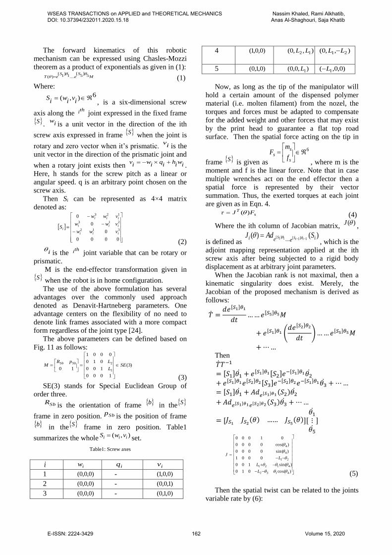
The forward kinematics of this robotic
mechanism can be expressed using Chasles-Mozzi
theorem as a product of exponentials as given in (1):
MS
eS
eT 5]
5[
....1]
1[
)(
(1)
Where:
6),(
iv
iw
iS
, is a six-dimensional screw
axis along the thi joint expressed in the fixed frame
S . iw
is a unit vector in the direction of the ith
screw axis expressed in frame S when the joint is
rotary and zero vector when it’s prismatic. iv
is the
unit vector in the direction of the prismatic joint and
when a rotary joint exists then iw
ih
iq
iw
iv
.
Here, h stands for the screw pitch as a linear or
angular speed. q is an arbitrary point chosen on the
screw axis.
Then Si can be represented as 4×4 matrix
denoted as:
0000
0
0
0
312
213
123
iii
iii
iii
ivww
vww
vww
S
(2)
i
is the thi joint variable that can be rotary or
prismatic.
M is the end-effector transformation given in S when the robot is in home configuration.
The use of the above formulation has several
advantages over the commonly used approach
denoted as Denavit-Hartneberg parameters. One
advantage centers on the flexibility of no need to
denote link frames associated with a more compact
form regardless of the joint type [24].
The above parameters can be defined based on
Fig. 11 as follows:
)3(
1000
100
010
0001
10 1
2SE
L
LpRM
SbSb
(3)
SE(3) stands for Special Euclidean Group of
order three.
SbR is the orientation of frame b in the S
frame in zero position. Sbp is the position of frame b in the S frame in zero position. Table1
summarizes the whole ),( iii vwS set.
Table1: Screw axes
i iw iq iv 1 )0,0,0( - )0,0,1( 2 )0,0,0( - )1,0,0( 3 )0,0,0( - )0,1,0(
4 )0,0,1( ),,0( 12 LL
),,0( 21 LL
5 )0,1,0( ),0,0( 1L )0,0,( 1L
Now, as long as the tip of the manipulator will
hold a certain amount of the dispensed polymer
material (i.e. molten filament) from the nozel, the
torques and forces must be adapted to compensate
for the added weight and other forces that may exist
by the print head to guarantee a flat top road
surface. Then the spatial force acting on the tip in
frame S is given as
6
s
ss
f
mF
, where m is the
moment and f is the linear force. Note that in case
multiple wrenches act on the end effector then a
spatial force is represented by their vector
summation. Thus, the exerted torques at each joint
are given as in Eqn. 4.
sT FJ )( (4)
Where the ith column of Jacobian matrix, )(J,
is defined as )()(
1]1[1]1[.... ieei SAdJ
iiSS
, which is the
adjoint mapping representation applied at the ith
screw axis after being subjected to a rigid body
displacement as at arbitrary joint parameters.
When the Jacobian rank is not maximal, then a
kinematic singularity does exist. Merely, the
Jacobian of the proposed mechanism is derived as
follows:
�̇� =𝑑𝑒[𝑆1]𝜃1
𝑑𝑡… … 𝑒[𝑆5]𝜃5𝑀
+ 𝑒[𝑆1]𝜃1 (𝑑𝑒[𝑆2]𝜃2
𝑑𝑡) … … 𝑒[𝑆5]𝜃5 𝑀
+ ⋯ … Then
�̇�𝑇−1
= [𝑆1]𝜃1̇ + 𝑒[𝑆1]𝜃1 [𝑆2]𝑒−[𝑆1]𝜃1𝜃2̇
+ 𝑒[𝑆1]𝜃1𝑒[𝑆2]𝜃2[𝑆3]𝑒−[𝑆2]𝜃2𝑒−[𝑆1]𝜃1𝜃3̇ + ⋯ …= [𝑆1]𝜃1̇ + 𝐴𝑑𝑒[𝑆1]𝜃1 (𝑆2)𝜃2̇
+ 𝐴𝑑𝑒[𝑆1]𝜃1𝑒[𝑆2]𝜃2 (𝑆3)𝜃3̇ + ⋯ …
= [𝐽𝑆1𝐽𝑆2
(𝜃) …… 𝐽𝑆5(𝜃)][
𝜃1̇
⋮𝜃5̇
]
)cos(010
)sin(100
0001
)sin(0000
)cos(0000
01000
4132
4121
21
4
4
L
L
LJ
(5)
Then the spatial twist can be related to the joints
variable rate by (6):
WSEAS TRANSACTIONS on APPLIED and THEORETICAL MECHANICS DOI: 10.37394/232011.2020.15.18
Nassim Khaled, Rami Alkhatib, Anas Al-Shaghouri, Saja Khatib
E-ISSN: 2224-3429 162 Volume 15, 2020

JV (6)
Moreover, by knowing the singularity,
appropriate analysis of the Jacobian matrix will help
in configuring different situations where the
manipulator tip is unable to produce velocities in
definite directions. On the other hand, if the tip of
the proposed mechanism is required to follow
predefined trajectory [£ (t)] then it becomes easy to
calculate the inverse kinematics θd(n∆t) at each
discrete timestamp n to control the joint velocities as
in (7):
θ̇ =[θd(n∆t)−θ((n−1)∆t)]
∆t (7)
From equation (7), we instilled feedback to
the controller by comparing the desired joint angle
with the most recently restrained real joint angle.
Alternatively, equation (6) can be
rearranged to (8):
�̇� = 𝐽−1𝑉𝑑 (8)
Where the desired twist can be the proposed
mechanism twist at the desired trajectory.
During mechanism motion, the controller is
provided by a steady stream of target positions and
orientations described in (1) and with velocities in
(6) and (8) that allow the mechanism track a certain
trajectory. This trajectory will be defined by the
software that slices the CAD model of the print into
layers. An operation signal is then sent to the
controller board based on the slices layers. The
controller than command the motors of the proposed
mechanism, print bed and the extruder.
6 Conclusion This paper is among the efforts in reducing or
removing supports in 3D printing operation in
correlation to fining degree of textures and
granularities that can be achieved. Some suggested
upgraded software that can decrease the number of
supports, some changed in material characteristics
or its type, and we are shedding the light on using
the mechanism to decrease the usage of support
structures. The usage of CAD/CAM software
solution will not remove the supports but will
optimize their position. And for the material change,
it may become costly more than the current
materials 3D printers use. As an advantage, our
mechanism works in conjunction with the 3D
printer nozzle under the monitoring of updated
software to work as in the proposed flowchart to
maximize the efficiency of 3D printing. A
mathematical formulation has been introduced along
with the mechanism design. The robotic arm has
been simulated in SolidWorks along with the 3D
printer mechanism.
As a conclusion, such introduced mechanisms can
solve the problem of exterior support structures in
FDM 3D printers with an acceptable cost. As a
matter of fact, we will achieve a better speed in the
3D printing process and thus saving time and
material usage for supports, eliminating the
constraints imposed by Earth’s gravity. The
mechanism is flexible and can adapt to different
positions needed for supports. Besides, it can move
around the 3D printer bed from three directions and
to move within the bed area. It is a wild concept to
build a 3D printer with built-in anti-support
mechanism, but better results could be achieved by
more research and experiments. For instance, the
proposed mechanism is not able to replace the
overhanging inner wall of an angle pipe structure.
Currently, In case of an arc exceeding the ability of
the end-effector, supports will be printed as
necessary. The software is built to compensate for
such scenarios.
As future work, the robot must be equipped with
advanced tools to overcome overhanging features
presented inside a complex geometry that block the
manipulator from reaching the inside.
References:
[1] D. Espalin, J. Ramierez, F. Medina and R.
Wicker, "Multi-Material, Multi-Technology FDM
System," University of Texas, El Paso, 2012.
[2] J. Vanek, J. A. G. Galicia, B. Benes, "Clever
Support: Efficient Support Structure Generation,"
Eurographics Symposium on Geometry Processing,
vol. 33 (2014), no. 5, 2014.
[3] W. R. Priedeman, A. L. Brosch and E. Prairie,
“Soluble material and process for three-dimensional
modeling". United States of America Patent US
6,790,403 B1, 14 September 2004.
[4] Greer, C (Greer, Clayton); Nycz, A (Nycz,
Andrzej); Noakes, M (Noakes, Mark); Richardson,
B (Richardson, Brad); Post, B (Post, Brian);
Kurfess, T (Kurfess, Thomas); Love, L (Love,
Lonnie), 2019. Introduction to the design rules for
Metal Big Area Additive Manufacturing.
ADDITIVE MANUFACTURING Volume: 27
Pages: 159-166 DOI: 10.1016/j.addma.2019.02.016.
[5] M. Leary, L. Merli, F. Torti, M. Mazur and M.
Brandt, "Optimal topology for additive manufacture:
A method for enabling additive manufacture of
support-free optimal structures," Materials and
Design, Elsevier , vol. 63, pp. 678-690, 2014.
[6] Zhao, D., & Guo, W. (2019). Mixed-layer
adaptive slicing for robotic Additive Manufacturing
(AM) based on decomposing and regrouping.
WSEAS TRANSACTIONS on APPLIED and THEORETICAL MECHANICS DOI: 10.37394/232011.2020.15.18
Nassim Khaled, Rami Alkhatib, Anas Al-Shaghouri, Saja Khatib
E-ISSN: 2224-3429 163 Volume 15, 2020

Journal of Intelligent
Manufacturing. doi:10.1007/s10845-019-01490-z [7] D. Ong U Jing, D. M. Devine and J. Lyons, "3D
Printed End of Arm Tooling (EOAT) for Robotic
Automation," Robotics Journal, Mdpi, vol. 7, no.
49, 2018.
[8] O. Kontovourkisa and G. Tryfonos, "Integrating
parametric design with robotic additive
manufacturing for 3D clay printing: An
experimental study," in 35th International
Symposium on Automation and Robotics in
Construction (ISARC 2018), 2018.
[9] I. Ishak, J. Fisher and P. Larochelle, "Robot Arm
Platform for Rapid Prototyping: Concept," in
Florida Conference on Recent Advances in
Robotics, FCRAR 2015, Melbourne, Florida, 2015.
[10] I. Ishak and P. Larochelle, "Robot Arm
Platform for Additive Manufacturing: 3D Lattice
Structures," in 30th Florida Conference on Recent
Advances in Robotics , Florida Atlantic University,
Boca Raton, Florida, May 11-12, 2017.
[11] M. Efe Tiryaki, X. Zhang and Q.-C. Pham,
"Printing-while-moving: a new paradigm for large-
scale robotic 3D Printing," in arXiv:1809.07940v1,
21 Sep 2018.
[12] P. Urhal, A. Weightman, C. Diver, P. Bartolo,
Robot assisted additive manufacturing: a review,
Rob. Comput. Integr. Manuf. 59 (2019) 335–345..
[13] S. Hongyao, P. Lingnan and Q. Jun, "Research
on large-scale additive manufacturing based on
multi-robot collaboration technology," Additive
Manufacturing, vol. 30, no.
https://doi.org/10.1016/j.addma.2019.100906, 2019.
[14] R. Alkhatib, W. Mechlawi and R. Kawtharani,
"Quality Assessment of Robotic Grasping Using
Regularized Logistic Regression," in IEEE Sensors
Letters, vol. 4, no. 6, pp. 1-4, June 2020, Art no.
5500904, doi: 10.1109/LSENS.2020.2994166..
[15] Scalera, L.; Palomba, I.; Wehrle, E.;
Gasparetto, A.; Vidoni, R. Natural Motion for
Energy Saving in Robotic and Mechatronic
Systems. Appl. Sci. 2019, 9, 3516..
[16] Carabin, G., Scalera, L., Wongratanaphisan, T.,
& Vidoni, R. (2021). An energy-efficient approach
for 3D printing with a Linear Delta Robot equipped
with optimal springs. Robotics and Computer-
Integrated Manufacturing, 67, 102045.
doi:10.1016/j.rcim.2020..
[17] Espera, A.H., Dizon, J.R.C., Chen, Q. et al. 3D-
printing and advanced manufacturing for
electronics. Prog Addit Manuf 4, 245–267 (2019).
https://doi.org/10.1007/s40964-019-00077-7.
[18] Jahan Zeb Gul, Memoon Sajid, Muhammad
Muqeet Rehman, Ghayas Uddin Siddiqui, Imran
Shah, Kyung-Hwan Kim, Jae-Wook Lee & Kyung
Hyun Choi (2018) 3D printing for soft robotics – a
review, Science and Technology of Advanced
Materials, 19:1, 243-262, DOI: 10.10.
[19] Shembekar, A. V., Yoon, Y. J., Kanyuck, A., and
Gupta, S. K. (April 1, 2019). "Generating Robot
Trajectories for Conformal Three-Dimensional
Printing Using Nonplanar Layers." ASME. J.
Comput. Inf. Sci. Eng. September 2019; 19(3):
031011, no. https://doi.org/10.1115/1.4043013.
[20] Subrin, K., Bressac, T., Garnier, S., Ambiehl,
A., Paquet, E., & Furet, B. (2018). Improvement of
the mobile robot location dedicated for habitable
house construction by 3D printing. IFAC-
PapersOnLine, 51(11), 716–721.
doi:10.1016/j.ifacol.2018.08.403.
[21] Joyee, E. B., & Pan, Y. (2020). Additive
manufacturing of multi-material soft robot for on-
demand drug delivery applications. Journal of
Manufacturing Processes, 56, 1178–1184.
doi:10.1016/j.jmapro.2020.03.059 .
[22] Freek Bos, Rob Wolfs, Zeeshan Ahmed & Theo
Salet (2016) Additive manufacturing of concrete in
construction: potentials and challenges of 3D
concrete printing, Virtual and Physical Prototyping,
11:3, 209-225, DOI:
10.1080/17452759.2016.1209867.
[23] B. J. Rao, "3D Printing a More Tangible Idea,"
7 January 2014. [Online]. Available:
http://heywhatsthebigidea.net/about-me/articles/3d-
printing-tangible-idea/.
[24] Al Hajjar, A., & Alkhatib, R. (2017). Agile
Locomotion. International Conference on
Bioengineering for Smart Technologies
(BioSMART 2016). Dubai, United Arab Emirates:
IEEE.
Author Contributions:
Nassim Khalid carried out the simulation and testing
of the proposed mechanism
Rami Alkharib carried the derivation of the
mathematical equations.
Anas Al-Shaghouri carried out the experimentations
and the verification of mathematical equations.
Saja Khatib was responsible for the manipulator
modelling.
Creative Commons Attribution License 4.0 (Attribution 4.0 International, CC BY 4.0)
This article is published under the terms of the Creative Commons Attribution License 4.0 https://creativecommons.org/licenses/by/4.0/deed.en_US
WSEAS TRANSACTIONS on APPLIED and THEORETICAL MECHANICS DOI: 10.37394/232011.2020.15.18
Nassim Khaled, Rami Alkhatib, Anas Al-Shaghouri, Saja Khatib
E-ISSN: 2224-3429 164 Volume 15, 2020