design of monopole antenna with u slot in patch and … · in patch and ground plane ideally suited...
TRANSCRIPT
Design Of Monopole Antenna With U Slot In Patch And Ground Plane Ideally Suited
For Wireless Applications Diptanuprasad Chakraborty
Department Of Electronics Engineering KIIT University, 751024, Bhubaneswar, Odisha, India
ABSTRACT- In this paper, a Monopole Antenna, square in shape, has been designed by cutting slots in both ground plane and patch for better impedance matching. The patch is assigned PEC material, and the substrate of the proposed antenna is Rogers RO3003(tm) having relative permittivity 3, and di-electric loss tangent of 0.0013. It is a Tri-band antenna having three resonant frequencies viz. 3.1GHz, 5.1GHz and 8.7GHz respectively, which exhibits same operating characteristics over a wider range of pass band. Comprehensive study of the frequency domain characteristics of the Antenna is being done, and is presented in this paper. The Antenna is simple and small in size, and is simulated using High Frequency Structure Simulator(HFSS) software. It is found to be suitable especially for Wireless Applications.
KEYWORDS- Monopole Antenna, Slotted Patch Antenna, Tri-Band Patch Antenna, U-shape Slotted Antenna, Inverted U-shape Slot, Square Monopole Antenna
I. INTRODUCTION With the advancement in technology, designers are more often leaned towards designing newer technologies that can have a wider range of operation, but will be having a less complex structure. Antennas are being used in communication between systems, radar systems, microwave high resolution imaging and other data transmission systems having higher speed. A monopole antenna is a type of radio antenna in which the conductor is mounted over the ground plane perpendicularly, and is a resonant type of antenna whose length is specified by the wavelength of radio waves. In this paper, a patch antenna having three resonant frequencies has been presented, which consists of a U-Shape Slot both in patch and ground plane. The ground plane is being printed on the back side of the substrate parallel to the 50Ω feed line, and consists of inverted U-Slot which ultimately helps in better impedance matching and obtaining linear polarization and narrow vertical radiation pattern. The three resonant frequencies of 3.1Ghz, 5.1Ghz and 8.7Ghz bears good bandwidth and gain with S11<-10db.
In antenna design, the main issue that is to be considered is regarding the compact design of antenna that could cover the entire frequency band. Many antennas are being developed over the years, and experiments were already being carried out by putting different shape slots in the antenna for maximizing the impedance bandwidth and improving the gain of the antenna. The proposed antenna in this paper, consists of U-Shape slots that are mainly used for bandwidth enhancement and achieving multiple bands. U-Slots were first proposed by Lee and Huynh in the year 1995, and since then, experiments are being carried out, which has proven that these slots can provide dual and multi-band characteristics. The impedance bandwidth directly depends on the type of material being used on the substrate, and due to this, RO3003(tm) substrate having low di-electric constant was chosen. VWSR, Gain, Return loss and other important characteristics of the antenna are being studied, and presented in this paper. . U-Slots were first proposed by Lee and Huynh in the year 1995, and since then, experiments are being carried out, which has proven that these slots can provide dual and multi-band characteristics. The impedance bandwidth directly depends on the type of material being used on the substrate, and due to this, RO3003(tm) substrate having low di-electric constant was chosen. VWSR, Gain, Return loss and other important characteristics of the antenna are being studied.
Note: The monopole antenna was invented in 1895 by radio pioneer Guglielmo Marconi, for this reason it is sometimes called a Marconi antenna. Common types of monopole antenna are the whip, rubber ducky, helical, random wire, umbrella, inverted-L and T-antenna, inverted-F, mast radiator, and ground plane antennas
II. ANTENNA DESIGN
The Proposed Monopole antenna is shown below in various figures, and it consists of a substrate which consists of Rogers RO3003(tm) material with relative permittivity 3, di-electric loss tangent 0.0013 and Lande G factor 2. The width of the microstrip feed line has been made as 2mm(W5), and length is 7mm(L4), which is used to feed the antenna in order to transmit and receive radio frequency waves. The basic structure of the antenna
e-ISSN : 0975-4024 Diptanuprasad Chakraborty / International Journal of Engineering and Technology (IJET)
p-ISSN : 2319-8613 Vol 8 No 2 Apr-May 2016 1131
consist othe substthe grounresonant relation:
The slot input impthe three & W2) an
Current which inBandwidby perfor
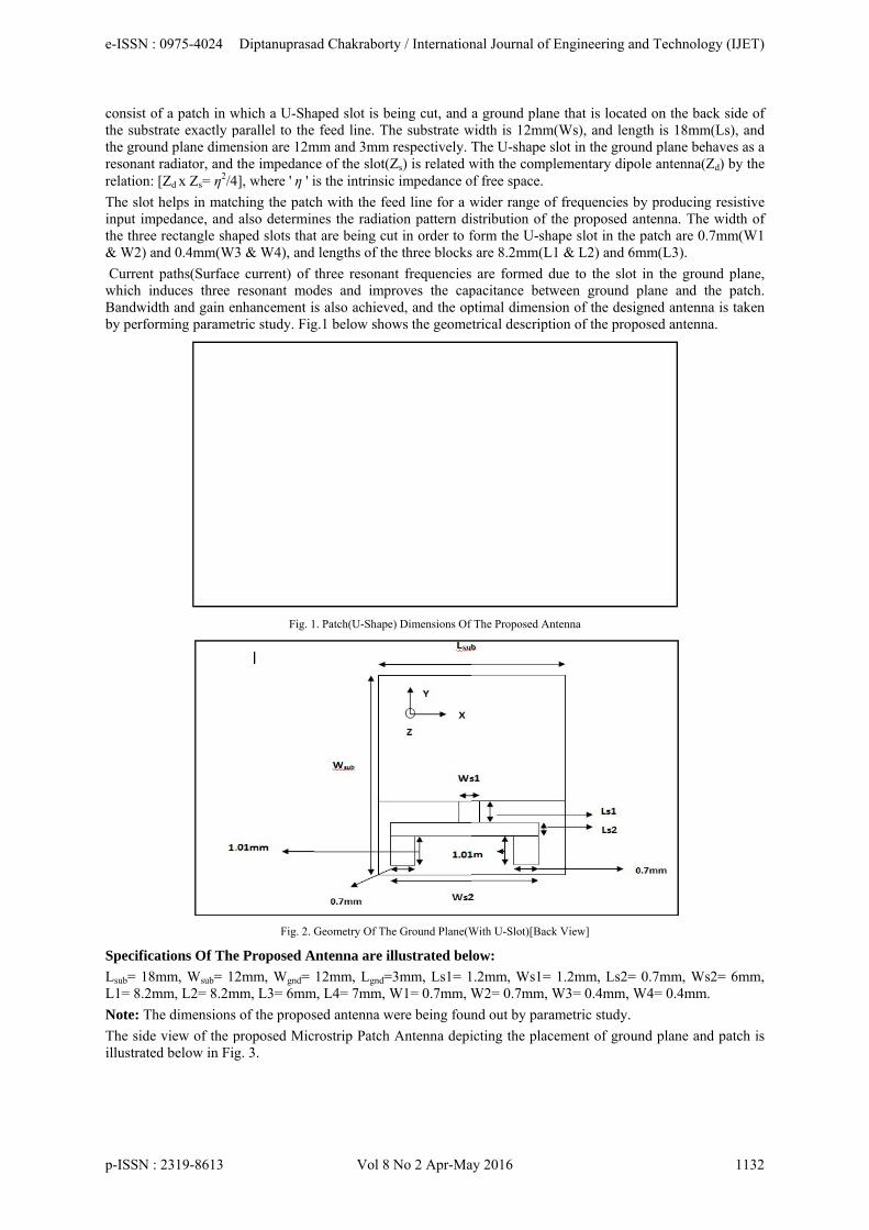
Specifica
Lsub= 18mL1= 8.2m
Note: Th
The side illustrated
of a patch in wtrate exactly pnd plane dimeradiator, and [Zd x Zs= ƞ2/4
helps in matcpedance, and rectangle sha
nd 0.4mm(W3
paths(Surfacenduces three dth and gain enrming parame
ations Of The
mm, Wsub= 12mm, L2= 8.2m
he dimensions
view of the pd below in Fig
which a U-Shaparallel to theension are 12mthe impedanc
4], where ' ƞ ' i
ching the patcalso determin
aped slots that3 & W4), and
e current) of resonant modnhancement itric study. Fig
Fig. 1
Fig. 2. G
e Proposed A
2mm, Wgnd= mm, L3= 6mm
of the propos
proposed Micg. 3.
aped slot is be feed line. Th
mm and 3mm ce of the slot(Zis the intrinsic
ch with the feenes the radiatit are being cu
d lengths of the
three resonandes and imprs also achieve
g.1 below show
1. Patch(U-Shape
Geometry Of The
Antenna are il
12mm, Lgnd=3m, L4= 7mm, W
sed antenna w
rostrip Patch
eing cut, and he substrate wrespectively. Zs) is related wc impedance o
ed line for a wion pattern di
ut in order to fe three blocks
nt frequenciesroves the caped, and the opws the geome
) Dimensions Of
e Ground Plane(W
llustrated bel
3mm, Ls1= 1W1= 0.7mm, W
were being foun
Antenna depi
a ground planwidth is 12mmThe U-shape with the compof free space.
wider range oistribution of form the U-shs are 8.2mm(L
are formed dpacitance betwptimal dimensetrical descript
f The Proposed An
With U-Slot)[Bac
low:
1.2mm, Ws1=W2= 0.7mm,
nd out by para
icting the plac
ne that is locam(Ws), and lenslot in the gro
plementary dip
of frequencies the proposed
hape slot in thL1 & L2) and
due to the sloween ground
sion of the destion of the pro
ntenna
ck View]
= 1.2mm, Ls2=W3= 0.4mm,
ametric study.
cement of gro
ated on the bacngth is 18mm
ound plane behpole antenna(Z
by producingantenna. The
he patch are 0.6mm(L3).
ot in the groud plane and tsigned antennoposed antenn
= 0.7mm, Ws, W4= 0.4mm
.
ound plane an
ck side of m(Ls), and haves as a Zd) by the
g resistive e width of .7mm(W1
und plane, the patch. na is taken na.
s2= 6mm, .
d patch is
e-ISSN : 0975-4024 Diptanuprasad Chakraborty / International Journal of Engineering and Technology (IJET)
p-ISSN : 2319-8613 Vol 8 No 2 Apr-May 2016 1132

ConsiderSoftwareassigned,The Simu
Inverted bandwidtpatch hasgain enhaparametr
Fig. 4 andistance, wide ban
A.
From Re
ring the dimene, and simulat, and the anteulated antenna
U-Shape Slotth. The basic s a width . Thancement is a
ric study.
nd Fig. 5 depthe sizes of U
ndwidth have b
Observations
turn Loss Cur
Resonant Fr
S11(In db) [R
Bandwidth(B
Fig
nsions mentioted after app
enna simulatioa is shown in
t was introduantenna struce patch is con
also achieved,
picts the Side U-shaped notcbeen optimize
I
rve:
equencies Ob F1(In GH
Return Loss O S11(F1)=
B.W)[In GHz
g. 3. Side View I
oned in Fig. plying correct on was being "Fig. 4 & Fig
Fig. 4. Side Vi
uced in the grcture consists nnected to a fe, and the optim
Fig. 5. Top Vi
and Top Viech, and the sized by parametr
III. OBSERV
btained: Hz)= 3.10GHzOr Reflection -38.22db, S11
z]:
Illustration Of Th
1 & Fig. 2, tport assignm
carried out a. 5" below.
iew Of The Anten
round plane inof a square p
eed line of widmal dimension
iew Of The Anten
ew of the antezes of two recric analysis.
VATIONS AN
z, F2(In GHz) Co-Efficient
1(F2)= -20.69d
he Proposed Anten
the proposed ment(Wave poafter assigning
nna(Simulated)
n order to obtpatch, a feed ldth and lengthn of the desig
nna(Simulated)
enna simulatectangular slots
ND RESULT
)= 5.10GHz, Ft]: db, S11(F3)= -
nna
antenna is beort). Proper A
g all the desig
tain better imine, and a gro
h , as shown ingned antenna
ed in HFSS Ss in the antenn
S
F3(In GHz)= 8
-37.61db
eing designedAir Box(Vacun parameters
mpedance matcound plane. Tn Fig.1. Bandwis taken by pe
Software. Thena’s patch to o
8.7GHz
d in HFSS uum) was correctly.
ching and The square width and erforming
e feed-gap obtain the
e-ISSN : 0975-4024 Diptanuprasad Chakraborty / International Journal of Engineering and Technology (IJET)
p-ISSN : 2319-8613 Vol 8 No 2 Apr-May 2016 1133
B.W(F1)= 0.89GHz, B.W(F2)= 0.83GHz, B.W(F3)= 3.10GHz. Gain(G)[In db]:
G(F1)= 8db, G(F2)= 6.20db, G(F3)= 3.25db Radiation Efficiency: 2.46
Important Note: The solution frequency is fixed at 2.45GHz for all the cases.
B. Results Return Loss:
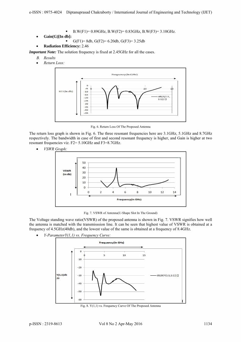
Fig. 6. Return Loss Of The Proposed Antenna
The return loss graph is shown in Fig. 6. The three resonant frequencies here are 3.1GHz, 5.1GHz and 8.7GHz respectively. The bandwidth in case of first and second resonant frequency is higher, and Gain is higher at two resonant frequencies viz. F2= 5.10GHz and F3=8.7GHz.
VSWR Graph:
Fig. 7. VSWR of Antenna(U-Shape Slot In The Ground)
The Voltage standing wave ratio(VSWR) of the proposed antenna is shown in Fig. 7. VSWR signifies how well the antenna is matched with the transmisssion line. It can be seen that highest value of VSWR is obtained at a frequency of 4.5GHz(40db), and the lowest value of the same is obtained at a frequency of 8.4GHz.
Y-ParameterY(1,1) vs. Frequency Curve:
Fig. 8. Y(1,1) vs. Frequency Curve Of The Proposed Antenna
e-ISSN : 0975-4024 Diptanuprasad Chakraborty / International Journal of Engineering and Technology (IJET)
p-ISSN : 2319-8613 Vol 8 No 2 Apr-May 2016 1134
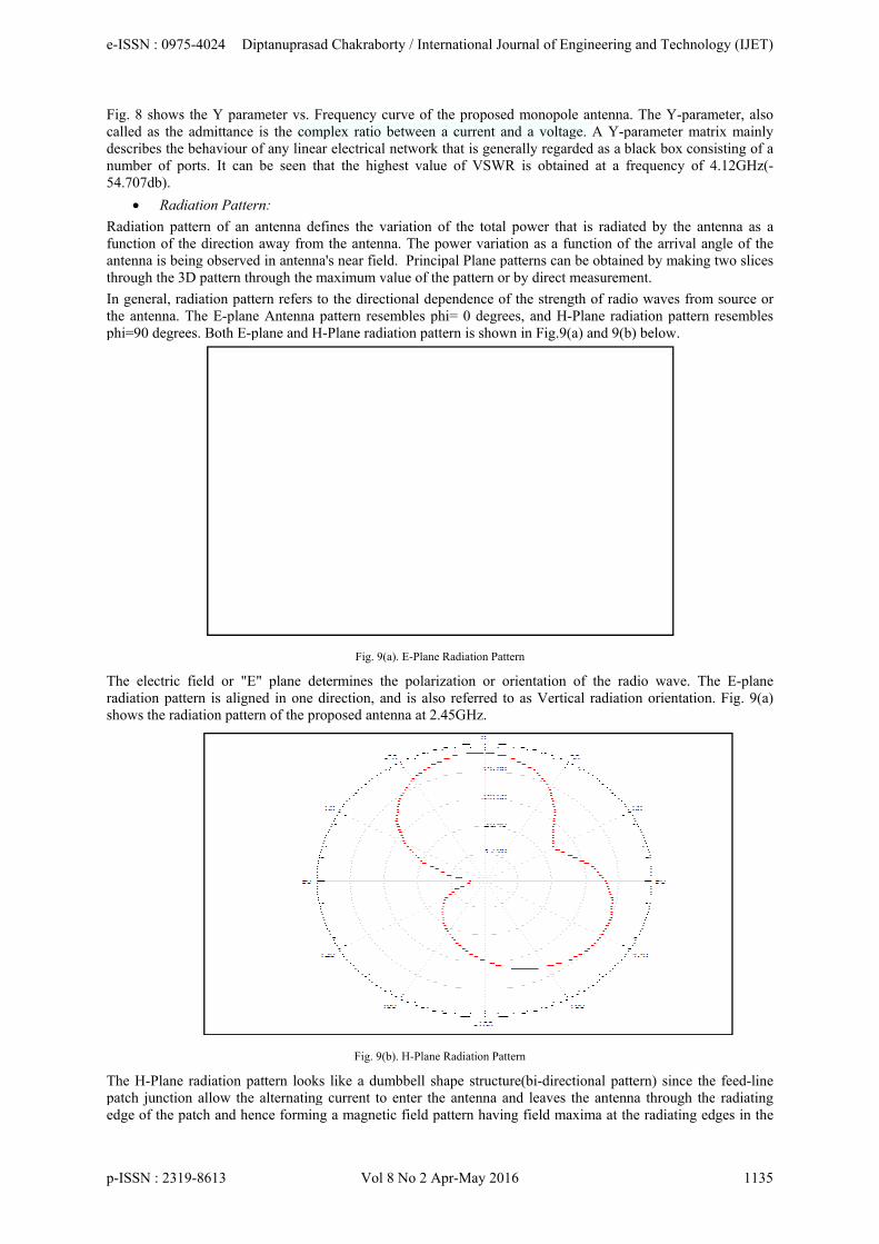
Fig. 8 shcalled asdescribesnumber o54.707db
Radiationfunction antenna ithrough t
In generathe antenphi=90 d
The elecradiationshows th
The H-Ppatch junedge of t
hows the Y pas the admittans the behaviouof ports. It cb).
Radiation Pa
n pattern of aof the directi
is being obserthe 3D pattern
al, radiation pnna. The E-pldegrees. Both E
ctric field or n pattern is alie radiation pa
lane radiationnction allow tthe patch and
arameter vs. Fnce is the comur of any lineacan be seen th
ttern:
an antenna deion away fromrved in antennn through the m
pattern refers tane Antenna E-plane and H
"E" plane deigned in one
attern of the pr
n pattern lookthe alternatinghence formin
Frequency curmplex ratio bear electrical nhat the highe
efines the varm the antennana's near field.maximum val
to the directiopattern resem
H-Plane radiat
Fig. 9(a).
etermines thedirection, androposed anten
Fig. 9(b).
ks like a dumbg current to eng a magnetic
rve of the proetween a curretwork that is
est value of V
riation of the a. The power v Principal Plaue of the patte
onal dependenmbles phi= 0 dtion pattern is
. E-Plane Radiati
e polarization d is also refernna at 2.45GH
. H-Plane Radiati
bbell shape stenter the anten
field pattern
oposed monoprent and a vols generally regVSWR is obt
total power tvariation as aane patterns cern or by direc
nce of the stredegrees, and shown in Fig
on Pattern
or orientatiorred to as Verz.
ion Pattern
tructure(bi-dirnna and leavehaving field m
pole antenna. ltage. A Y-pagarded as a bltained at a fr
that is radiatea function of tcan be obtainect measureme
ength of radioH-Plane radia.9(a) and 9(b)
on of the radrtical radiation
rectional pattees the antennamaxima at the
The Y-paramarameter matrack box consiequency of 4
ed by the antthe arrival an
ed by making tent.
o waves from ation pattern r) below.
dio wave. Then orientation.
ern) since thea through thee radiating ed
meter, also rix mainly isting of a 4.12GHz(-
enna as a gle of the two slices
source or resembles
e E-plane Fig. 9(a)
e feed-line radiating
dges in the
e-ISSN : 0975-4024 Diptanuprasad Chakraborty / International Journal of Engineering and Technology (IJET)
p-ISSN : 2319-8613 Vol 8 No 2 Apr-May 2016 1135
directionto dipoleof the pro
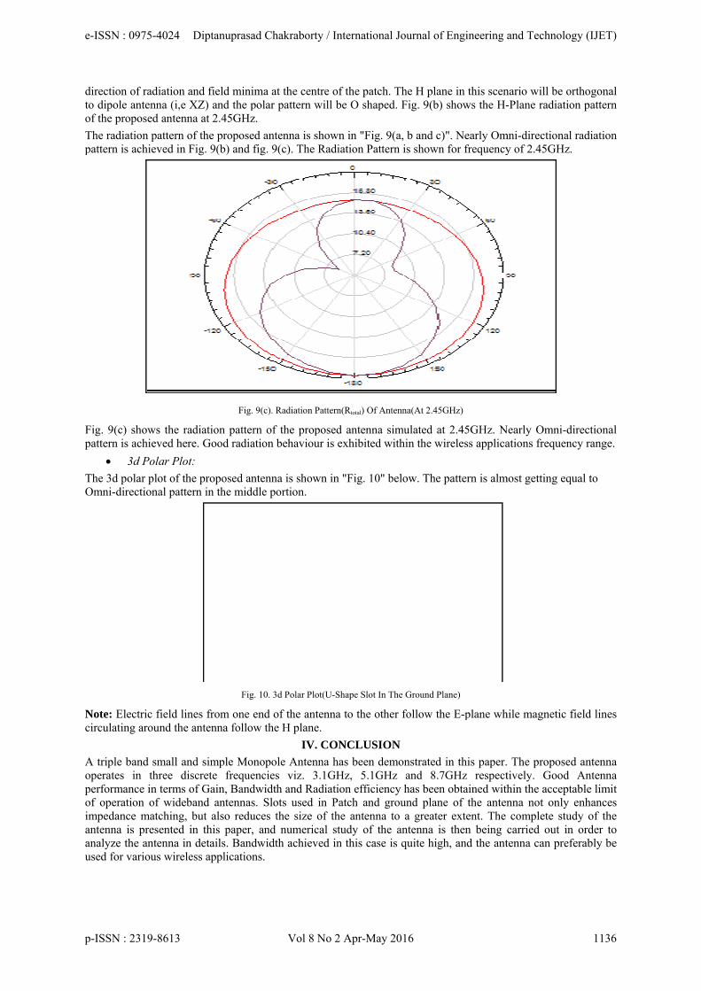
The radiapattern is
Fig. 9(c)pattern is
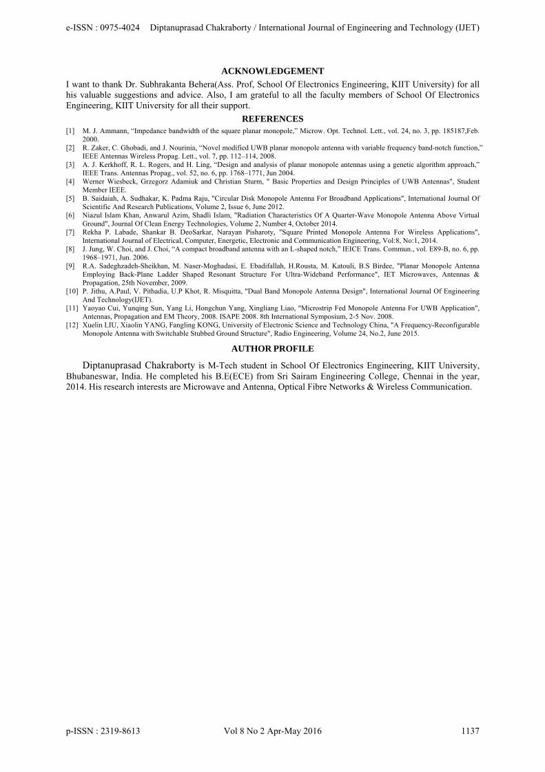
The 3d pOmni-dir
Note: Elcirculatin
A triple boperates performaof operatimpedancantenna analyze tused for v
n of radiation a antenna (i,e Xoposed antenn
ation pattern os achieved in F
shows the ras achieved her
3d Polar Plot
olar plot of threctional patte
ectric field linng around the
band small anin three di
ance in terms otion of widebce matching, is presented ithe antenna invarious wirele
and field miniXZ) and the pna at 2.45GHz
of the proposeFig. 9(b) and f
Fig.
adiation patterre. Good radia
t:
he proposed anern in the midd
Fig
nes from one eantenna follow
nd simple Monscrete frequeof Gain, Bandband antennasbut also reduin this paper,
n details. Bandess application
ima at the cenpolar pattern wz.
ed antenna is sfig. 9(c). The
9(c). Radiation P
rn of the propation behaviou
ntenna is showdle portion.
g. 10. 3d Polar Plo
end of the antw the H plane
IV.
nopole Antenencies viz. 3dwidth and Ras. Slots used uces the size and numericdwidth achievns.
tre of the patcwill be O shap
shown in "FigRadiation Pat
Pattern(Rtotal) Of A
posed antennaur is exhibited
wn in "Fig. 10
ot(U-Shape Slot I
tenna to the oe.
. CONCLUSI
nna has been d3.1GHz, 5.1Gadiation efficiein Patch and of the antenncal study of tved in this cas
ch. The H planped. Fig. 9(b)
. 9(a, b and c)ttern is shown
Antenna(At 2.45G
a simulated atd within the wi
" below. The
In The Ground Pl
ther follow th
ION
demonstrated GHz and 8.7ency has beenground plane
na to a greaterthe antenna isse is quite high
ne in this scenshows the H-
)". Nearly Omn for frequency
GHz)
t 2.45GHz. Nireless applica
pattern is alm
lane)
he E-plane wh
in this paper.7GHz respectn obtained withe of the antenr extent. The s then being h, and the ant
nario will be o-Plane radiatio
mni-directionaly of 2.45GHz
Nearly Omni-dations frequen
most getting eq
hile magnetic f
The proposetively. Good hin the acceptnna not only complete stu
carried out intenna can pref
orthogonal on pattern
l radiation .
directional ncy range.
qual to
field lines
d antenna Antenna
table limit enhances
udy of the n order to ferably be
e-ISSN : 0975-4024 Diptanuprasad Chakraborty / International Journal of Engineering and Technology (IJET)
p-ISSN : 2319-8613 Vol 8 No 2 Apr-May 2016 1136
ACKNOWLEDGEMENT
I want to thank Dr. Subhrakanta Behera(Ass. Prof, School Of Electronics Engineering, KIIT University) for all his valuable suggestions and advice. Also, I am grateful to all the faculty members of School Of Electronics Engineering, KIIT University for all their support.
REFERENCES [1] M. J. Ammann, “Impedance bandwidth of the square planar monopole,” Microw. Opt. Technol. Lett., vol. 24, no. 3, pp. 185187,Feb.
2000. [2] R. Zaker, C. Ghobadi, and J. Nourinia, “Novel modified UWB planar monopole antenna with variable frequency band-notch function,”
IEEE Antennas Wireless Propag. Lett., vol. 7, pp. 112–114, 2008. [3] A. J. Kerkhoff, R. L. Rogers, and H. Ling, “Design and analysis of planar monopole antennas using a genetic algorithm approach,”
IEEE Trans. Antennas Propag., vol. 52, no. 6, pp. 1768–1771, Jun 2004. [4] Werner Wiesbeck, Grzegorz Adamiuk and Christian Sturm, " Basic Properties and Design Principles of UWB Antennas", Student
Member IEEE. [5] B. Saidaiah, A. Sudhakar, K. Padma Raju, "Circular Disk Monopole Antenna For Broadband Applications", International Journal Of
Scientific And Research Publications, Volume 2, Issue 6, June 2012. [6] Niazul Islam Khan, Anwarul Azim, Shadli Islam, "Radiation Characteristics Of A Quarter-Wave Monopole Antenna Above Virtual
Ground", Journal Of Clean Energy Technologies, Volume 2, Number 4, October 2014. [7] Rekha P. Labade, Shankar B. DeoSarkar, Narayan Pisharoty, "Square Printed Monopole Antenna For Wireless Applications",
International Journal of Electrical, Computer, Energetic, Electronic and Communication Engineering, Vol:8, No:1, 2014. [8] J. Jung, W. Choi, and J. Choi, “A compact broadband antenna with an L-shaped notch,” IEICE Trans. Commun., vol. E89-B, no. 6, pp.
1968–1971, Jun. 2006. [9] R.A. Sadeghzadeh-Sheikhan, M. Naser-Moghadasi, E. Ebadifallah, H.Rousta, M. Katouli, B.S Birdee, "Planar Monopole Antenna
Employing Back-Plane Ladder Shaped Resonant Structure For Ultra-Wideband Performance", IET Microwaves, Antennas & Propagation, 25th November, 2009.
[10] P. Jithu, A.Paul, V. Pithadia, U.P Khot, R. Misquitta, "Dual Band Monopole Antenna Design", International Journal Of Engineering And Technology(IJET).
[11] Yaoyao Cui, Yunqing Sun, Yang Li, Hongchun Yang, Xingliang Liao, "Microstrip Fed Monopole Antenna For UWB Application", Antennas, Propagation and EM Theory, 2008. ISAPE 2008. 8th International Symposium, 2-5 Nov. 2008.
[12] Xuelin LIU, Xiaolin YANG, Fangling KONG, University of Electronic Science and Technology China, "A Frequency-Reconfigurable Monopole Antenna with Switchable Stubbed Ground Structure", Radio Engineering, Volume 24, No.2, June 2015.
AUTHOR PROFILE
Diptanuprasad Chakraborty is M-Tech student in School Of Electronics Engineering, KIIT University, Bhubaneswar, India. He completed his B.E(ECE) from Sri Sairam Engineering College, Chennai in the year, 2014. His research interests are Microwave and Antenna, Optical Fibre Networks & Wireless Communication.
e-ISSN : 0975-4024 Diptanuprasad Chakraborty / International Journal of Engineering and Technology (IJET)
p-ISSN : 2319-8613 Vol 8 No 2 Apr-May 2016 1137