design of parallel-jaw gripper tip surfaces for robust...
TRANSCRIPT

Design of Parallel-Jaw Gripper Tip Surfaces for Robust Grasping
Menglong Guo1, David V. Gealy1, Jacky Liang2, Jeffrey Mahler2,Aimee Goncalves1, Stephen McKinley1, Juan Aparicio Ojea3, Ken Goldberg4
Abstract— Parallel-jaw robot grippers can grasp almost anyobject and are ubiquitous in industry. Although the shape,texture, and compliance of gripper jaw surfaces affect grasprobustness, almost all commercially available grippers providea pair of rectangular, planar, rigid jaw surfaces. Practitionersoften modify these surfaces with a variety of ad-hoc methodssuch as adding rubber caps and/or wrapping with texturedtape. This paper explores data-driven optimization of gripperjaw surfaces over a design space based on shape, texture,and compliance using rapid prototyping. In total, 37 jawsurface design variations were created using 3D printed castingmolds and silicon rubber. The designs were evaluated with1377 physical grasp experiments using a 4-axis robot (withautomated reset). These tests evaluate grasp robustness as theprobability that the jaws will acquire, lift, and hold a trainingset of objects at nominal grasp configurations computed byDex-Net 1.0. Hill-climbing in parameter space yielded a gridpattern of 0.03 inch void depth and 0.0375 inch void width ona silicone polymer with durometer of A30. We then evaluatedperformance of this design using an ABB YuMi robot graspinga set of eight difficult-to-grasp 3D printed objects in 80 graspswith four gripper surfaces. The factory-provided gripper tipssucceeded in 28.7% of the 80 trials, increasing to 68.7% whenthe tips were wrapped with tape. Gripper tips with gecko-inspired surfaces succeeded in 80.0% of trials, and gripper tipswith the designed silicone surfaces succeeded in 93.7% of trials.
I. INTRODUCTION
”Building more general hands for robots that re-quire very little customization, that can dynami-cally grasp millions of different sized and shapedobjects, that can do so quickly, that have a longlifetime over millions of cycles, and that just workwould have significant impact on deployment ofrobots in factories, in fulfillment centers, and inhomes.” - Rod Brooks, February 2017 [1]
Parallel-jaw grippers are widely used in the current gen-eration of human-compliant robots, such as Sawyer fromRethink Robotics [2] or the YuMi from ABB [3], due to theirlow complexity, long lifetime, and ability to precisely manip-ulate objects [4]. Despite the intention that these robots beused in unstructured environments, such as homes and ware-house order fulfillment centers, most robots come equipped
1University of California, Berkeley, Mechanical Engineering;{m.guo,dgealy,asgoncalves,mckinley}@berkeley.edu
2University of California, Berkeley, EECS;{jackyliang, jmahler}@berkeley.edu
3Siemens Research;[email protected]
4University of California, Berkeley, IEOR & EECS;[email protected]
The AUTOLAB at UC Berkeley (automation.berkeley.edu)
Fig. 1: Top: Grasp robustness for 37 gripper surfaces was evaluatedusing a 4-dof robot with a custom ”reset” mechanism that includesan activated rewind mechanism and cable that lifts and replaces theobject onto the worksurface in an upright position after each grasp.Bottom: Each gripper surface was cast in silicone polymer usingcustom 3D-printed molds.
with parallel-jaw grippers that conform to the industrialparadigm of planar, rigid jaws [5]. Robots operating in theseunstructured environments may benefit from compliant end-effectors that are designed to successfully manipulate a widevariety of shapes and textures while resisting torques due tocontact and gravity [6].
We explore options for adding compliant and high-frictionjaw surfaces to standard parallel-jaw grippers. A varietyof designs have been proposed such as rubber coverings,polymer pancakes [7], and human-inspired skin, bone, nailstructures [8, 9], and gecko-inspired surfaces that resisttangential foces [10]. The design process for these surfaceshas been largely guided by human intuition and optimizationin simulation [11], and often only one or a small number ofdesigns have been physically realized due to the time and

material cost of manufacturing. However, the gripper/objectsurface interaction is difficult to predict in simulation andrequires modeling assumptions that may not be met inpractice [12].
Inspired by recent advances in 3D printing and rapidprototyping, we explore the possibility of guiding the designprocess empirically by evaluating success on a physicalsystem for a large number of prototype fingertip designs. Ourprimary contribution is an extensive evaluation of grippersurface texture and stiffness for compliant robotic fingers (asshown in dark blue in Fig. 1) across 37 iterations of surfacefeatures (Fig. 4). Each design was parametrized and proto-typed using 3D printing and molded silicone. We iterativelyevaluated the probability of grasp success for our designset, inspired by resampling-based optimization methods suchas zooming [13] and the cross entropy method [14], andexpanded our design set around the most promising designfrom the previous evaluations. We collected between 21 and35 grasp trials for each design across three 3D printed objectson a 4-dof Zymark Zymate robot for a total of 1377 totalevaluations.Initial Assumptions: The Series Type A Pro 3D printersextrude Polylactic Acid (PLA). Platinum-cure silicon rubberwas used for a compliant material because it is robust,easy to manufacture and can be washed. Grasps were testedwith a Zymark Zymate 2 laboratory robot (equipped withparallel jaws) with positional uncertainty of up to 5mm anda pointcloud-based vision system with positional error of upto 1cm. Known objects from the Dex-Net 1.0 dataset [15]were used to test grasps.
II. RELATED WORK
A. Related work in gripper design
An important tool for design inspiration is the idea ofutilizing nature as a model. This technique, known asbiomimicry, is highly useful for robotic gripper design. Twospecific areas this design concept has been applied to arestructural and surface features.
Structurally, a typical industrial robotic finger consists ofa single, uniform, rigid material throughout, regardless of itsshape. However, anthropomorphic observations reveal thathuman fingers consist of several layers: bone, soft tissue,skin, and nails, where each of these characteristics provide aunique function for human grasping. To increase the abilityof a robotic hand, Murakami et al. [8] explored addinga hard nail with a strain gauge to a fingertip covered bysoft elastic. Hosoda et al. evaluated these characteristicsas well by using a metal bar and two types of siliconerubber to replicate the bone-body-skin structure [9]. Tostudy the benefits of compliance on surface contact gripping,Berselli et al. designed and tested soft fingertip covers withfour varied internal geometric structures, relying on rapidprototyping for inexpensive fingertip production [16]. Addi-tionally, in both [9] and [17], embedded strain gauges wereadded (randomly and strategically-placed, respectively) intosilicone gripper pads to replicate sense of touch and provideuseful tactile feedback during manipulation. All of these
anthropomorphic-inspired designs revealed the effectivenessof utilizing multiple structural materials, geometries, andfeatures when designing grippers for manipulation purposes.
Nature-inspired surface features have been investigated fortheir various attractive properties. Initially motivated by thefingerprint surfaces on human hands, Cutkosky et al. foundthat textured and compliant gripper surfaces improved objecthandling [18]. Research stemming from fingerprint analysishas led to the development of gecko-inspired adhesives,which replicate the strong adhesion gecko feet possess [19].Pairing this material with grippers is a successful techniquefor manipulation. For example, Hawkes et al. developedgrippers that use shear adhesion of gecko-inspired fibrillarfilm micro-structures to grasp curved objects [20].
From the previous work on bio-inspired adhesion, it hasbeen suggested that interface geometry is important for ad-hesion. To try and provide insight on adhesion mechanisms,uniform surface patterns were explored by Crosby et al. [7].Described as polymer ’pancakes’, tests were run for surfaceswith a range of cylindrical posts with varying heights,diameters, and grid-spacing. These patterned dimensionswere linked to material properties which increase grip forcefor sliding contact; from this, adhesion effect relationshipswere extracted between surface dimensions and materialproperties. This conceptual surface feature inspired initialdesign concepts in Section III.
Fig. 2: The 37 gripper surface designs, with 3D printed molds (inwhite) used for fabrication.
B. Designing from Soft Contact Model Results
One strategy for compliant robotic finger design is to useanalytic soft contact models [21]. These models take intoaccount contact area and tangential friction forces in additionto normal friction forces, where the Soft Contact Modelutilizes the power law to relate contact radius to the normalforce exerted by compliant fingertips.
Design research in this area has focused on matchingempirical results to the analytic contact models. For example,Han et al. [22] developed a model for maximum staticfriction on human fingers by first measuring friction ofa human finger and fitting the data to the Hertz contactmodel. The friction model’s results were then compared toresulting friction properties of a silicone finger. Similarly,
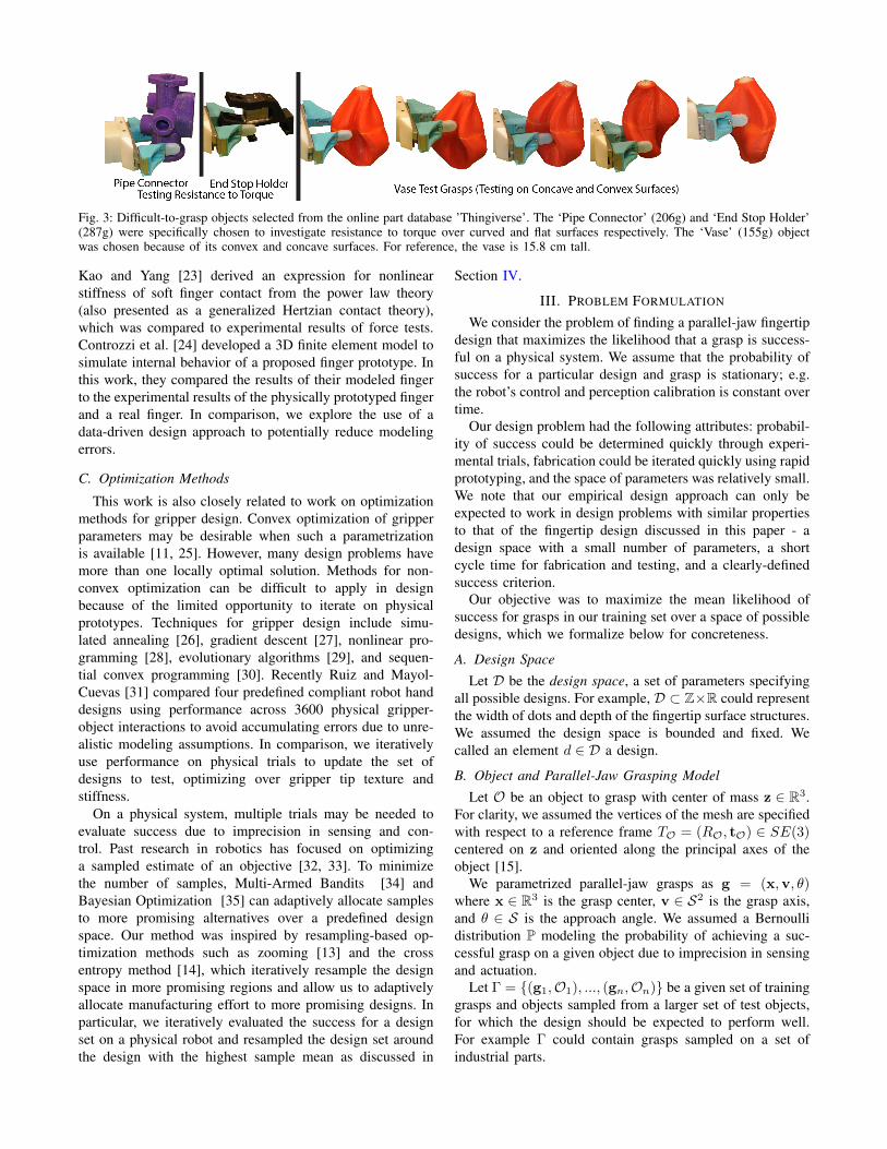
Fig. 3: Difficult-to-grasp objects selected from the online part database ’Thingiverse’. The ‘Pipe Connector’ (206g) and ‘End Stop Holder’(287g) were specifically chosen to investigate resistance to torque over curved and flat surfaces respectively. The ‘Vase’ (155g) objectwas chosen because of its convex and concave surfaces. For reference, the vase is 15.8 cm tall.
Kao and Yang [23] derived an expression for nonlinearstiffness of soft finger contact from the power law theory(also presented as a generalized Hertzian contact theory),which was compared to experimental results of force tests.Controzzi et al. [24] developed a 3D finite element model tosimulate internal behavior of a proposed finger prototype. Inthis work, they compared the results of their modeled fingerto the experimental results of the physically prototyped fingerand a real finger. In comparison, we explore the use of adata-driven design approach to potentially reduce modelingerrors.
C. Optimization Methods
This work is also closely related to work on optimizationmethods for gripper design. Convex optimization of gripperparameters may be desirable when such a parametrizationis available [11, 25]. However, many design problems havemore than one locally optimal solution. Methods for non-convex optimization can be difficult to apply in designbecause of the limited opportunity to iterate on physicalprototypes. Techniques for gripper design include simu-lated annealing [26], gradient descent [27], nonlinear pro-gramming [28], evolutionary algorithms [29], and sequen-tial convex programming [30]. Recently Ruiz and Mayol-Cuevas [31] compared four predefined compliant robot handdesigns using performance across 3600 physical gripper-object interactions to avoid accumulating errors due to unre-alistic modeling assumptions. In comparison, we iterativelyuse performance on physical trials to update the set ofdesigns to test, optimizing over gripper tip texture andstiffness.
On a physical system, multiple trials may be needed toevaluate success due to imprecision in sensing and con-trol. Past research in robotics has focused on optimizinga sampled estimate of an objective [32, 33]. To minimizethe number of samples, Multi-Armed Bandits [34] andBayesian Optimization [35] can adaptively allocate samplesto more promising alternatives over a predefined designspace. Our method was inspired by resampling-based op-timization methods such as zooming [13] and the crossentropy method [14], which iteratively resample the designspace in more promising regions and allow us to adaptivelyallocate manufacturing effort to more promising designs. Inparticular, we iteratively evaluated the success for a designset on a physical robot and resampled the design set aroundthe design with the highest sample mean as discussed in
Section IV.
III. PROBLEM FORMULATION
We consider the problem of finding a parallel-jaw fingertipdesign that maximizes the likelihood that a grasp is success-ful on a physical system. We assume that the probability ofsuccess for a particular design and grasp is stationary; e.g.the robot’s control and perception calibration is constant overtime.
Our design problem had the following attributes: probabil-ity of success could be determined quickly through experi-mental trials, fabrication could be iterated quickly using rapidprototyping, and the space of parameters was relatively small.We note that our empirical design approach can only beexpected to work in design problems with similar propertiesto that of the fingertip design discussed in this paper - adesign space with a small number of parameters, a shortcycle time for fabrication and testing, and a clearly-definedsuccess criterion.
Our objective was to maximize the mean likelihood ofsuccess for grasps in our training set over a space of possibledesigns, which we formalize below for concreteness.
A. Design Space
Let D be the design space, a set of parameters specifyingall possible designs. For example, D ⊂ Z×R could representthe width of dots and depth of the fingertip surface structures.We assumed the design space is bounded and fixed. Wecalled an element d ∈ D a design.
B. Object and Parallel-Jaw Grasping Model
Let O be an object to grasp with center of mass z ∈ R3.For clarity, we assumed the vertices of the mesh are specifiedwith respect to a reference frame TO = (RO, tO) ∈ SE(3)centered on z and oriented along the principal axes of theobject [15].
We parametrized parallel-jaw grasps as g = (x,v, θ)where x ∈ R3 is the grasp center, v ∈ S2 is the grasp axis,and θ ∈ S is the approach angle. We assumed a Bernoullidistribution P modeling the probability of achieving a suc-cessful grasp on a given object due to imprecision in sensingand actuation.
Let Γ = {(g1,O1), ..., (gn,On)} be a given set of traininggrasps and objects sampled from a larger set of test objects,for which the design should be expected to perform well.For example Γ could contain grasps sampled on a set ofindustrial parts.
C. Design Objective
Let Si(d) be a binary random variable measuring thesuccess of using design d to execute grasp gi on Oi. Our goalwas to find the design that maximizes the mean likelihoodof success for grasps in our test set (shown in Figure 3):
d∗ = argmaxd∈D
1
n
n∑i=1
P (Si(d) = 1) (1)
which is the expected number of successes for a uniformdistribution over the dataset Γ.
D. Methodology
Solving Equation 1 may be very difficult in practice dueto the large number of possible designs, grasps, and objects.Our approach to this problem was inspired by resamplingoptimization methods [13, 14], which iteratively evaluate aset of points and resample near the best points. We firstformed an initial discrete set of designs sampled from anumber of concepts, such as different surface features andfingertip geometries. We then evaluated the probability ofsuccess for all designs on all grasps and objects in ourtraining set by sampling. Specifically, we estimated theprobability of success by taking the percentage of successesover m total trials
PS(d,gi,Oi) =1
m
m∑j=1
1(Si,j(d) = 1)
where Si,j(d) is the j-th sample of Si(d) and 1(·) isthe indicator function. We then expanded our design setby sampling a grid of design parameters around the bestperforming design from the initial set. Finally, we repeatedlyevaluated and resampled for k rounds, choosing the designwith the highest sample mean as d∗ at termination. We usedk = 3 and m = 3 in our experiments based on the amountof time to run each trial and round of evaluations.
IV. EXPERIMENTAL DETAILS
A. Fabrication of Gripper Surfaces
Molds were created with Series 1 Pro Type A 3D printersfrom Polylactic acid (PLA) filament. This manufacturingstep limited the resolution of surface textures to 0.1 mm. 3Dprinted mounts on the parallel jaws of the robot allowed forquick swapping of grippers for testing and minimized thedevelopment cost per iteration. Each gripper had an identicalbase printed from PLA filament to index into the mount. Thebase served as a hard plastic structure for the soft siliconerubber tips to be cast around. The unique texture surface wascreated by casting the base in 3D printed molds (Fig. 5).
B. Dataset
Our design test set Γ consisted of seven total grasps acrossthree objects (Fig. 3). The dataset was selected to test (a)resistance to torques about the principal grasp axis, which aredifficult to resist with two fingers [5], and (b) adaptivity tovarying geometric features such as concavities, convexities,and ridges.
TABLE I: Silicone Rubber Properties (Manufactured by Smooth-On)
Silicone Rubber Softness(Durometer)
Stiffness(Elongation at Break %)
Mold Star 30 30A 339%Dragon Skin 30 30A 364%Dragon Skin 10 10A 1000%Eco Flex 00-20 00-20 845%
The two grasps on the end stop holder and pipe connectorwere chosen to test (a) torque resistance and the five graspson the vase were chosen to test (b) geometric adaptivity.Each object was also labeled with a single stable pose on thetable chosen for reachability with our 4 degree of freedomarm. All grasps were hand-selected from a set of contactpoints generated using the antipodal grasp sampling of Dex-Net 1.0 [15], and the approach axis was constrained to beparallel to the table for the given stable pose.
C. Experimental Platform
Grasping trials were run on a Zymark Zymate 2 robotwith 4 degrees of freedom plus gripper control and a rotatingturntable for 5 total controllable degrees of freedom (Fig. 1).To begin an experiment, a test object was placed onto theworkspace table in a pre-defined stable pose and attachedto a reset mechanism. For each grasp trial, a PrimeSenseCarmine 1.09 depth sensor was used to register the pose ofthe object. After registration, the robot proceeded to performa chosen grasp by planning a straight line trajectory to thedesired grasp pose, moving to the pose, and closing its jaws.The robot then attempted to raise the object by 17.5mm, atwhich point the PrimeSense camera took a color picture forlabeling. This concluded a single trial. To begin the next trial,the reset mechanism then raised and lowered the test objectback to the known stable pose on the work table.
Registration was performed using convolutional neuralnetworks for a coarse pose estimate [36] and Iterated ClosestPoint matching with a weighted point-to-plane objective [37]for fine pose estimation in the plane of the table. The regis-tration system had a mean X translational error of 4.2mm, amean Y translational error of 1.0 mm, and a mean angularerror of 5.1◦ in the plane. The standard deviations were3.1mm, 3.3mm, and 8.6◦ for X translation, Y translation,and rotation in the plane, respectively.
D. Grasp Success Criteria
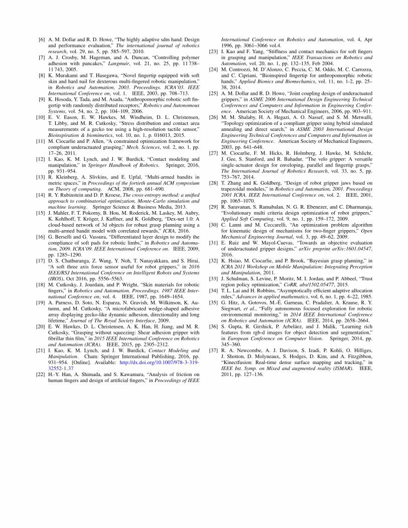
Each grasp was considered a success or failure basedon the criteria illustrated in Fig. 6. We considered a graspattempt a failure if it fell into one of three modes:
1) Drop: The gripper failed to lift/hold the object.2) Slip: The gripper lifted the object but the object rotated
by more than 10 degrees about the principal grasp axis.3) Cage: The gripper lifted the object upright but leveraged
a part of the gripper other than the fingertip surface.Therefore a grasp was considered successful if it lifted theobject in an upright position using only the fingertips.
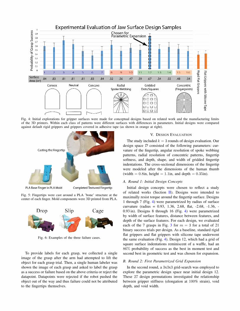
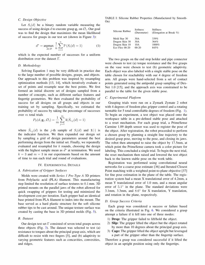
Fig. 4: Initial explorations for gripper surfaces were made for conceptual designs based on related work and the manufacturing limitsof the 3D printers. Within each class of patterns were different surfaces with differences in parameters. Initial designs were comparedagainst default rigid grippers and grippers covered in adhesive tape (as shown in orange at right).
Fig. 5: Fingertips were cast around a PLA ’bone’ structure at thecenter of each finger. Mold components were 3D printed from PLA.
Fig. 6: Examples of the three failure cases.
To provide labels for each grasp, we collected a singleimage of the grasp after the arm had attempted to lift theobject for each grasp trial. Then, a single human labeler wasshown the image of each grasp and asked to label the graspas a success or failure based on the above criteria or reject thedatapoint. Datapoints were rejected if the robot pushed theobject out of the way and thus failure could not be attributedto the fingertips themselves.
V. DESIGN EVALUATION
The study included k = 3 rounds of design evaluation. Ourdesign space D consisted of the following parameters: cur-vature of the fingertip, angular resolution of spoke webbingpatterns, radial resolution of concentric patterns, fingertipsoftness, and depth, shape, and width of gridded fingertipindentations. The cross-sectional dimensions of the fingertipwere modeled after the dimensions of the human thumb(width = 0.8in, height = 1.1in, and depth = 0.35in).
A. Round 1: Initial Design Concepts
Initial design concepts were chosen to reflect a studyof related works (Section II). Designs were intended tomaximally resist torque around the fingertip surface. Designs1 through 7 (Fig. 4) were parametrized by radius of surfacecurvature (radius = 0.93, 1.36, 2.68, flat, -2.68, -1.36, -0.93 in). Designs 8 through 16 (Fig. 4) were parametrizedby width of surface features, distance between features, anddepth of the surface features. For each design, we evaluatedeach of the 7 grasps in Fig. 3 for m = 3 for a total of 21binary success trials per design. As a baseline, standard rigidflat grippers and flat grippers with silicone tape underwentthe same evaluation (Fig. 4). Design 12, which had a grid ofsquare surface indentations reminiscent of a waffle, had an86% probability of success as the best in moment test andsecond best in geometric test and was chosen for expansion.
B. Round 2: First Parametrized Grid Expansion
In the second round, a 3x3x3 grid-search was employed toexplore the parametric design space near initial design 12.These 27 design permutations investigated the relationshipbetween gripper stiffness (elongation at 100% strain), voiddepth, and void width.

Fig. 7: The first round of parametric expansion investigates theeffect of material stiffness, void depth, and void width on the mostsuccessful design from the initial set (Fig. 4) through a 3x3x3 cubeof possibilities. Success was found to be linked to lower stiffnessand diminished void width.
Parameters Explored:Materials: Dragon Skin 30 (DS30), Mold Star 30 (MS30),and a 50:50 mixture between DS30 and MS30.Void Width: 0.03 0.0375 0.045 in.Void Depth: 0.03, 0.05, 0.07 in.
Again, for each design we evaluated each of the 7 graspsin Fig. 3 for m = 3 samples. The results of the secondround are illustrated in Fig. 7. The results suggest that lowerstiffness materials and shallower indentation depth performedbetter. The best performing design had the same indentationdepth and width as design 12 with lower stiffness, which hada 90% probability of success.
C. Round 3: Second Parametrized Grid Expansion
In this grid expansion, we investigated the square indentedgripper with further exploration of void depth. We alsoexplored material softness.
Parameters Explored:Materials: Dragon Skin 30, Dragon Skin 10, Eco-Flex 00-20.Void Depth: 0.02, 0.03 in.
We were forced to use a backup Zymark robot in ourdesign evaluations because the robot we tested on in the
first two rounds malfunctioned. Thus, we ran the same 7grasps but with m = 5 samples each instead of 3 becausewe found that the backup robot was noisier and we neededto reject more samples for each design. The results areillustrated in Fig. 8. We found that further softening thematerial and reducing the depth of the indentations decreasedthe probability of success. Furthermore, all designs had alower probability of success on the backup robot.
The most successful design d∗ was the winner of roundtwo, which had a void depth of 0.03in, a void width of0.0375in, and a durometer of A30.
Fig. 8: A second round of parametric expansion further exploredthe effect of smaller void depth and material softness on graspingsuccess. The most successful design was fabricated four moretimes and tested on the same conditions to verify manufacturingrepeatability (shown at right in dark blue).
D. Manufacturing Repeatability
We made 4 additional copies of d∗ and evaluated theprobability of success for each independently in order tomeasure the repeatability of our manufacturing process. Theresults are illustrated in the right panel of Fig. 8. We foundthat the designs have different success probabilities rangingfrom 47% to 65% with a mean of 55% and a standarddeviation of approximately 7%. This suggests that variabilityin our manufacturing process affects the success of thedesign. However, even in the worst case the design had ahigher estimated success probability than the other designsfrom the second grid expansion.
E. Manufacturing and Evaluation Time
Considerable time was saved throughout this process byusing rapid prototyping to make many unique molds and us-ing a reset mechanism to autonomously test the grippers witha real robot. The manufacturing process to create 16 uniquegrippers in the initial design phase took approximately 11.5hours, including a 10 hour time period where the operatorhad to wait for the machine to print and the silicone toset. During grasp evaluation, each grasp took approximately1.5 minutes to execute. With 1377 total grasps, the totalgrasp experiment time was 31 hours. However, the resetmechanism allowed the test to be run autonomously, so the

operator only spent about 2 hours changing grippers betweentests.
F. Comparing four gripper tip surfaces on 320 grasp trials.
The highest-performing gripper surface was evaluated us-ing eight 3D printed objects using the ABB Yumi industrialrobot (Fig. 9. The factory-provided gripper tips succeededin 28.7% of the 80 trials, increasing to 68.7% when the tipswere wrapped with tape. Gripper tips with gecko-inspiredsurfaces succeeded in 80.0% of trials, and gripper tips withthe designed silicone surfaces succeeded in 93.7% of trials.(Fig. 10).
Fig. 9: (above) After the gripper tip surface design process, an ABBYumi industrial robot was used to compare four gripper tip surfacesusing a test set of eight objects: 80 trials for each gripper tip surface.(below) The four gripper tip surfaces from left to right: ABB defaultgrippers, ABB grippers wrapped with electrical tape, the siliconedesign described above, and the gecko-inspired tip surfaces.
VI. DISCUSSION AND FUTURE WORK
We evaluated gripper surface texture and stiffness forcompliant robotic fingertips across 37 iterations of individualconceptual surface features and 1377 grasping evaluations ina hill-climbing approach to optimizing gripper tip surfaces.We do not claim to have found the optimal gripper in thisspace but performance was slightly higher than that withgecko-inspired surfaces designed to resist tangential forces.The difference in performance may be attributed to the roughsurfaces of the 3D printed objects, as well as the torsional
Fig. 10: Results of 320 grasp trials: 80 trials with each grippersurface.
loading of the gripper. Gecko adhesive is optimized forsmooth surfaces, and shear activated adhesion is directionalwhich results in a rotational slip failure mode. In future work,we will continue to explore the design space using Multi-Armed Bandit search methods and explore the addition ofembedded force sensors.
Acknowledgements
This research was performed at the AUTOLAB atUC Berkeley in affiliation with the AMP Lab, BAIR,and the CITRIS ‘People and Robots’ Initiative (CPAR):(robotics.citris-uc.org).
The authors were supported in part by the U.S. NationalScience Foundation under NRI Award IIS-1227536: Multilat-eral Manipulation by Human-Robot Collaborative Systems,by the Department of Defense (DoD) through the NationalDefense Science & Engineering Graduate Fellowship (ND-SEG) Program, and by Siemens Corporation. Any opinions,findings, and conclusions or recommendations expressed inthis material are those of the authors and do not neces-sarily reflect the views of the sponsors. We are grateful toour colleagues at Stanford for providing the gecko-inspiredgripper surface material, in particular Mark Cutkosky, ElliotHawkes, and Wilson Ruotolo, with special help from VincentDuchaine of ETS Montreal.
REFERENCES
[1] R. Brooks, “Research needed on robot hands,” Jan 2017. [Online].Available: https://rodneybrooks.com/research-needed-on-robot-hands/
[2] rethink robotics, “Sawyer user guide for intera 3.3 software,”http://mfg.rethinkrobotics.com/mfg-mediawiki-1.22.2/images/1/1a/Sawyer User Guide 3.3.pdf, 2016.
[3] P. Crowther, “Yumi® irb 15000 overview,” https://library.e.abb.com/public/4bcf2603f76f49088b80f7f1c49045eb/IRB14000ExternalVersionFinal.pdf, 2015.
[4] A. Bicchi and A. Marigo, “Dexterous grippers: Putting nonholonomyto work for fine manipulation,” The International Journal of RoboticsResearch, vol. 21, no. 5-6, pp. 427–442, 2002.
[5] A. Bicchi and V. Kumar, “Robotic grasping and contact: A review,” inIEEE International Conference on Robotics and Automation. Citeseer,2000, pp. 348–353.
[6] A. M. Dollar and R. D. Howe, “The highly adaptive sdm hand: Designand performance evaluation,” The international journal of roboticsresearch, vol. 29, no. 5, pp. 585–597, 2010.
[7] A. J. Crosby, M. Hageman, and A. Duncan, “Controlling polymeradhesion with pancakes,” Langmuir, vol. 21, no. 25, pp. 11 738–11 743, 2005.
[8] K. Murakami and T. Hasegawa, “Novel fingertip equipped with softskin and hard nail for dexterous multi-fingered robotic manipulation,”in Robotics and Automation, 2003. Proceedings. ICRA’03. IEEEInternational Conference on, vol. 1. IEEE, 2003, pp. 708–713.
[9] K. Hosoda, Y. Tada, and M. Asada, “Anthropomorphic robotic soft fin-gertip with randomly distributed receptors,” Robotics and AutonomousSystems, vol. 54, no. 2, pp. 104–109, 2006.
[10] E. V. Eason, E. W. Hawkes, M. Windheim, D. L. Christensen,T. Libby, and M. R. Cutkosky, “Stress distribution and contact areameasurements of a gecko toe using a high-resolution tactile sensor,”Bioinspiration & biomimetics, vol. 10, no. 1, p. 016013, 2015.
[11] M. Ciocarlie and P. Allen, “A constrained optimization framework forcompliant underactuated grasping,” Mech. Sciences, vol. 2, no. 1, pp.17–26, 2011.
[12] I. Kao, K. M. Lynch, and J. W. Burdick, “Contact modeling andmanipulation,” in Springer Handbook of Robotics. Springer, 2016,pp. 931–954.
[13] R. Kleinberg, A. Slivkins, and E. Upfal, “Multi-armed bandits inmetric spaces,” in Proceedings of the fortieth annual ACM symposiumon Theory of computing. ACM, 2008, pp. 681–690.
[14] R. Y. Rubinstein and D. P. Kroese, The cross-entropy method: a unifiedapproach to combinatorial optimization, Monte-Carlo simulation andmachine learning. Springer Science & Business Media, 2013.
[15] J. Mahler, F. T. Pokorny, B. Hou, M. Roderick, M. Laskey, M. Aubry,K. Kohlhoff, T. Kroger, J. Kuffner, and K. Goldberg, “Dex-net 1.0: Acloud-based network of 3d objects for robust grasp planning using amulti-armed bandit model with correlated rewards,” ICRA, 2016.
[16] G. Berselli and G. Vassura, “Differentiated layer design to modify thecompliance of soft pads for robotic limbs,” in Robotics and Automa-tion, 2009. ICRA’09. IEEE International Conference on. IEEE, 2009,pp. 1285–1290.
[17] D. S. Chathuranga, Z. Wang, Y. Noh, T. Nanayakkara, and S. Hirai,“A soft three axis force sensor useful for robot grippers,” in 2016IEEE/RSJ International Conference on Intelligent Robots and Systems(IROS), Oct 2016, pp. 5556–5563.
[18] M. Cutkosky, J. Jourdain, and P. Wright, “Skin materials for roboticfingers,” in Robotics and Automation. Proceedings. 1987 IEEE Inter-national Conference on, vol. 4. IEEE, 1987, pp. 1649–1654.
[19] A. Parness, D. Soto, N. Esparza, N. Gravish, M. Wilkinson, K. Au-tumn, and M. Cutkosky, “A microfabricated wedge-shaped adhesivearray displaying gecko-like dynamic adhesion, directionality and longlifetime,” Journal of The Royal Society Interface, 2009.
[20] E. W. Hawkes, D. L. Christensen, A. K. Han, H. Jiang, and M. R.Cutkosky, “Grasping without squeezing: Shear adhesion gripper withfibrillar thin film,” in 2015 IEEE International Conference on Roboticsand Automation (ICRA). IEEE, 2015, pp. 2305–2312.
[21] I. Kao, K. M. Lynch, and J. W. Burdick, Contact Modeling andManipulation. Cham: Springer International Publishing, 2016, pp.931–954. [Online]. Available: http://dx.doi.org/10.1007/978-3-319-32552-1 37
[22] H.-Y. Han, A. Shimada, and S. Kawamura, “Analysis of friction onhuman fingers and design of artificial fingers,” in Proceedings of IEEE
International Conference on Robotics and Automation, vol. 4, Apr1996, pp. 3061–3066 vol.4.
[23] I. Kao and F. Yang, “Stiffness and contact mechanics for soft fingersin grasping and manipulation,” IEEE Transactions on Robotics andAutomation, vol. 20, no. 1, pp. 132–135, Feb 2004.
[24] M. Controzzi, M. D’Alonzo, C. Peccia, C. M. Oddo, M. C. Carrozza,and C. Cipriani, “Bioinspired fingertip for anthropomorphic robotichands,” Applied Bionics and Biomechanics, vol. 11, no. 1-2, pp. 25–38, 2014.
[25] A. M. Dollar and R. D. Howe, “Joint coupling design of underactuatedgrippers,” in ASME 2006 International Design Engineering TechnicalConferences and Computers and Information in Engineering Confer-ence. American Society of Mechanical Engineers, 2006, pp. 903–911.
[26] M. M. Shalaby, H. A. Hegazi, A. O. Nassef, and S. M. Metwalli,“Topology optimization of a compliant gripper using hybrid simulatedannealing and direct search,” in ASME 2003 International DesignEngineering Technical Conferences and Computers and Information inEngineering Conference. American Society of Mechanical Engineers,2003, pp. 641–648.
[27] M. Ciocarlie, F. M. Hicks, R. Holmberg, J. Hawke, M. Schlicht,J. Gee, S. Stanford, and R. Bahadur, “The velo gripper: A versatilesingle-actuator design for enveloping, parallel and fingertip grasps,”The International Journal of Robotics Research, vol. 33, no. 5, pp.753–767, 2014.
[28] T. Zhang and K. Goldberg, “Design of robot gripper jaws based ontrapezoidal modules,” in Robotics and Automation, 2001. Proceedings2001 ICRA. IEEE International Conference on, vol. 2. IEEE, 2001,pp. 1065–1070.
[29] R. Saravanan, S. Ramabalan, N. G. R. Ebenezer, and C. Dharmaraja,“Evolutionary multi criteria design optimization of robot grippers,”Applied Soft Computing, vol. 9, no. 1, pp. 159–172, 2009.
[30] C. Lanni and M. Ceccarelli, “An optimization problem algorithmfor kinematic design of mechanisms for two-finger grippers,” OpenMechanical Engineering Journal, vol. 3, pp. 49–62, 2009.
[31] E. Ruiz and W. Mayol-Cuevas, “Towards an objective evaluationof underactuated gripper designs,” arXiv preprint arXiv:1601.04547,2016.
[32] K. Hsiao, M. Ciocarlie, and P. Brook, “Bayesian grasp planning,” inICRA 2011 Workshop on Mobile Manipulation: Integrating Perceptionand Manipulation, 2011.
[33] J. Schulman, S. Levine, P. Moritz, M. I. Jordan, and P. Abbeel, “Trustregion policy optimization,” CoRR, abs/1502.05477, 2015.
[34] T. L. Lai and H. Robbins, “Asymptotically efficient adaptive allocationrules,” Advances in applied mathematics, vol. 6, no. 1, pp. 4–22, 1985.
[35] G. Hitz, A. Gotovos, M.-E. Garneau, C. Pradalier, A. Krause, R. Y.Siegwart, et al., “Fully autonomous focused exploration for roboticenvironmental monitoring,” in 2014 IEEE International Conferenceon Robotics and Automation (ICRA). IEEE, 2014, pp. 2658–2664.
[36] S. Gupta, R. Girshick, P. Arbelaez, and J. Malik, “Learning richfeatures from rgb-d images for object detection and segmentation,”in European Conference on Computer Vision. Springer, 2014, pp.345–360.
[37] R. A. Newcombe, A. J. Davison, S. Izadi, P. Kohli, O. Hilliges,J. Shotton, D. Molyneaux, S. Hodges, D. Kim, and A. Fitzgibbon,“Kinectfusion: Real-time dense surface mapping and tracking,” inIEEE Int. Symp. on Mixed and augmented reality (ISMAR). IEEE,2011, pp. 127–136.