design of reinforced concrete structures prof. nirjhar ......have to provide the reinforcement of a...
TRANSCRIPT
Design of Reinforced Concrete Structures
Prof. Nirjhar Dhang
Department of Civil Engineering
Indian Institute of Technology, Kharagpur
Lecture - 16
Design of Slabs Part III
We shall continue, with the same design of slabs and this is our part 3. So, lecture 16
design of slabs part 3 that we shall continue
(Refer Slide Time: 01:33)
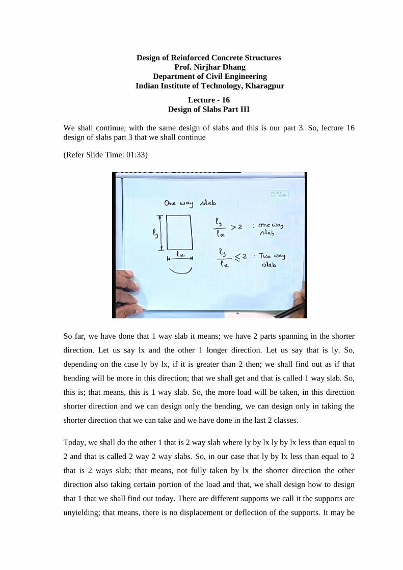
So far, we have done that 1 way slab it means; we have 2 parts spanning in the shorter
direction. Let us say lx and the other 1 longer direction. Let us say that is ly. So,
depending on the case ly by lx, if it is greater than 2 then; we shall find out as if that
bending will be more in this direction; that we shall get and that is called 1 way slab. So,
this is; that means, this is 1 way slab. So, the more load will be taken, in this direction
shorter direction and we can design only the bending, we can design only in taking the
shorter direction that we can take and we have done in the last 2 classes.
Today, we shall do the other 1 that is 2 way slab where ly by lx ly by lx less than equal to
2 and that is called 2 way 2 way slabs. So, in our case that ly by lx less than equal to 2
that is 2 ways slab; that means, not fully taken by lx the shorter direction the other
direction also taking certain portion of the load and that, we shall design how to design
that 1 that we shall find out today. There are different supports we call it the supports are
unyielding; that means, there is no displacement or deflection of the supports. It may be

we can define it say this is your as, if it supported over the masonry wall and this 1 we
can take it as is simply supported case simply supported.
It can have certain kind of like this, there is a end beam say there is end beam and the
reinforcement at the top. We shall get and then at the bottom also we have to provide the
reinforcement generally, it happens the reinforcement this length that is 0.1 and this is
restrained. So, 1 case is simply supported but, we are taking all of them that is supports
are unlinked that there will be no deflection of the support; example you can say as, if it
is not spring mounted the supports are not spring mounted.
(Refer Slide Time: 3:35)
So, simply supported then we can take say strength the other 1 we can take. So, this is
your continuous. So, continuous support it may be beam or it may be wall also. So, these
are the 3 different supports that we take it for the design of slabs and in all the cases. We
have to take that ly by lx the longer duration the span in the longer duration divided by
the span, in the shorter direction should be less than equal to 2 that is our case. In that
case only we can design it as I say 2 way slabs, we can design that 1 as a 2 way slab only
1 we shall get ly by lx less than equal to 2.
There are few more cases we can take that 1 generally it happens; the things that what I
mean to say this is your 1 corner initially, it was like this. This is 1 corner and the due to
say simply supported case it will happen say if you put a plate like this due to bending
what will happen, you will find out that corners that will go up. So, if I have to keep it in

proper position. So, you have to provide reinforcement of the top as well as the bottom
that also you have to provide the reinforcement.
So, it is to so, here just what I am trying to show that if it have say corners are there that
is 1 is possible case that corners are restrained or corners are not restrained. That if I
have to restrain your corner; that means, you have to provide reinforcement in each
corner but, that is true only where we have to provide the reinforcement, we have to
provide the reinforcement only, in the corner that discontinuous the corner which is the
support which is continuous.
There you need not specify you have to specify the that reinforcement only that y of the
corner that you say isolated corner 1 force on this way or the other way, but, not like this.
It may happen say something like this that; this is your panel. Let us say and we are
providing say different beams. So, this is I am talking say plan these on I am talking plan
and these are all beams to be more specific I can say there are so, many columns maybe,
we can specify the column at each beam column junction here or it can be alternate also
depending on the design.
So, we can say these are all each panel and i am talking this 1 plan. So, what we can do
we have to design each of them depending on the ly by lx ratio. Let us say in this side all
of them having certain portion. Let us say we can specify say 3 meter each something
like that we can specify. This side also we can specify say 3 or 3 0.5 something like that
let us say: not each of them we have to find out depending on the ly by lx we have to
design it and design it as 2 way slab in this case, what we have to do.
This is your 1 corner where it may happen that corner will go off so; that means, you
have to provide the reinforcement of a certain distance you have to provide the
reinforcement here sorry here like this. But, need not provide reinforcement here we
need not provide reinforcement here, but at the same time we have to provide
reinforcement here, because this 1. There is a discontinuity this side there is no edge. So,
we have to provide the reinforcement only where we do not have any continuity. So,
there you have to provide the corner reinforcement. That we shall that also we have to
design and we have to provide reinforcement. That we shall that also we have to design
and we have to provide reinforcement.

(Refer Slide Time: 06:53)
So, now let us come the few cases another 1; I can tell you that it happens because, due
to dislift it may happen; there is a crack here why you do have to provide just for you for
the reason that generally, if it lifts there is a possibility of crack here. So, to work on that
care we provide the reinforcement in these corners. But whereas, in the continuous 1
since it is by all 4 sides. So, no need of provide that corner reinforcement yes; it will lift
because of that at the bottom also that tension compression that will happen and that it
will you will get that crack.
(Refer Slide Time: 11:59)

Now, let us come to the 1 case that moments in 2 way slabs special case say simply
supported on all supports please note the supports are on yielding that supports, will not
be deflected this is a 1 case I can say as if we are having the slab which is supported over
brick wall in all 4 sides. So, brick wall in all 4 sides and we have to design that we have
to find out that moment distribution; that means, whatever the load we are getting here
may we can say uniformally distributed load.
Let us say: that is q we can say let us take centre to centre distance or the effective span
whatever we call it this is lx and the other side we are having ly. So, we can get that lx
and ly and then the total uniformally distributed load over this q; that means, you say 4
kilo Newton per square meter and including you say also that 1 we can take. So, when
you having this 1 we can say we have to find out that how much is qx; that means, qx
and how much you will be you say qy that qx; that means, if I take a stripe say this is
your 1 stripe may be 1 meter width the other 1 let us take around the y.
So, this 1 also will be bend the other 1 also will bend. Now, what we can find out that we
can find out at this point the vertical deflection. So, since there is no stripes if I take this
stripe that; as if 1 plate the other side also 1 another plate. So, the deflection here we
shall get it whatever deflection, we shall get it the deflection will be the same taking this
1 and taking other another one. So, this is our consideration and from that point of view
we can find out the distribution of qx and qy.
We can take qx and qy on the basis of that, we have taking that q due to qx what is the
vertical deflection here and due to qy say what will be the deflection and that; 1 should
be equal, because there is no difference say otherwise both of them deform the same time
and there is no disconnection. So, that is why you can take that 1 displacement same the
vertical displacement same that is our assumption.
(Refer Slide Time: 15:58)
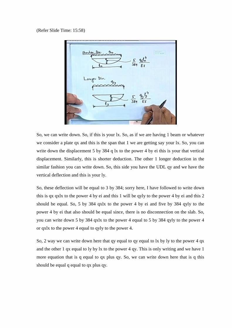
So, we can write down. So, if this is your lx. So, as if we are having 1 beam or whatever
we consider a plate qx and this is the span that 1 we are getting say your lx. So, you can
write down the displacement 5 by 384 q lx to the power 4 by ei this is your that vertical
displacement. Similarly, this is shorter deduction. The other 1 longer deduction in the
similar fashion you can write down. So, this side you have the UDL qy and we have the
vertical deflection and this is your ly.
So, these deflection will be equal to 3 by 384; sorry here, I have followed to write down
this is qx qxlx to the power 4 by ei and this 1 will be qyly to the power 4 by ei and this 2
should be equal. So, 5 by 384 qxlx to the power 4 by ei and five by 384 qyly to the
power 4 by ei that also should be equal since, there is no disconnection on the slab. So,
you can write down 5 by 384 qxlx to the power 4 equal to 5 by 384 qyly to the power 4
or qxlx to the power 4 equal to qyly to the power 4.
So, 2 way we can write down here that qy equal to qy equal to lx by ly to the power 4 qx
and the other 1 qx equal to ly by lx to the power 4 qy. This is only writing and we have 1
more equation that is q equal to qx plus qy. So, we can write down here that is q this
should be equal q equal to qx plus qy.

(Refer Slide Time: 19:57)
So, we write down here qx plus lx by ly to the power 4 qx equal to q or qx 1 plus lx to
the power 4 by ly to the power 4 equal to q therefore, qx equal to q times ly to the power
4 by lx to the power 4 plus ly to the power 4 equals q ly by lx to the power 4 divided by
1 plus ly by lx to the power 4.
So, this is your that equation qx. So, you can write down this 1 depending on the ly by lx
we can find out what will be the contribution of qx here. Similarly, we can write down
the other portion also. Similarly, we can write down the other portion also that what is
the how much will be that qy. So, we can write down and we can actually, we can make
it. Let us come previous 1 that moment mx equal to qx l square x by 8 equals q times we
can write down the whole thing.
So, here we can write down q times ly by lx to the power 4 by 1 plus ly by lx to the
power 4 into 1 by 8 l square x equal to we can write down as beta x times qu l square x
beta x means; taking care of whole thing including 1 by 8. So, that we can take it and that
is beta x and q l square x. So, mx will be equal to beta x and q l square x. So, mx will be
equal to beta x q l square x, please note we have written in this fashion. The other 1 you
have to find out the moment. We are taking care moment bending moment due to this q
which can get 1 coefficient called x. So, that 1 will be equal to mx equal to beta x q l
square x.
(Refer Slide Time: 22:45)

.
The same fashion we can write down here again; q equal to qx plus qy or we can write
down here that ly by lx 4 qy plus qy qx equal to this much equal to q or we can write
down as qy equal to sorry, I think I can make it here like this ly to the power 4 by lx to
the power 4 plus 1 equal to q or qy ly to the power 4 plus lx to the power 4 by lx to the
power 4 equal to q or qy equal to lx to the power 4 by lx t the power 4 by ly to the power
4 times q. So, this is your q that we can get it so; obviously, this 1 will be lx to the power
4 by lx to the power 4 plus ly to the power 4 this much we can get it.
(Refer Slide Time: 24:17)
So, what about your my then. So, we can write down here my will be equal to qy l square
y by 8 that is due to simply supported case. For simply supported case, we are getting

this much the qy that is the contribution that is the 1 that; we shall get it in the qy side.
So, that is for simply supported case in the longer direction. So, you can write down here
1 by 8 lx to the power 4 by lx to the power 4 plus ly to the power 4 times q times l square
y equals.
We can write down here as 1 by 8 1 divided by 1 plus ly by lx to the power 4 times q l
square y 1 by 8 1 by 1 plus ly by lx to the power 4 q ly square just, I have divided by lx
to the power 4; which we can further write down as 1 by 8 what I shall do it here. Let us
divided by lx square and times lx so, what shall I do it here 1 by 1 plus ly by lx to the
power 4 times ly square by l square x times q times l square x, I shall write down this 1
as because I know everything we always mention here that ly by lx since why mention it
ly by lx.
(Refer Slide Time: 26:35)
So, we shall write down that my that 1 will be equal to times q l square x. So, what we
can do it here then; we can get it my equal to 1 by 8 ly by lx whole square divided by 1
plus ly by lx to the power 4 times q l square x. So, we can write down as my equal to
beta y q l square x. So, please note if I write down the same mx then; it will be clear. So,
mx equal to we have written as 1 by 8 ly by lx to the power please note, but, has square 1
plus ly by lx to the power 4 times q l square x and which; we have written as beta x q l
square x.

So, you are getting 2 equations in no case we are interested to get that ly. So, please note
when you are doing your computation for moment, because you are interested to find out
the moment only mx and my for simply supported case. So, what we shall do it here we
have to get beta x and beta y we shall get beta x and beta y and times q l square x; when
you are calculating my and similarly, when you are calculating mx that time also it is q l
square x please note that it is not that ly square and lx square generally you that do that
mistake.
(Refer Slide Time: 28:38)
But, please note that in both the cases; we are taking the ql square x and beta x and beta y
that they are coefficients and these coefficients also you need not calculate again; what
you have to do they are those coefficients will get it in table 27 is 4 5 6 2000. So, you can
get that 1 table just to mention this table means; bending movement, coefficients for
slabs spanning in 2 directions at right angles that these are not 29.29 right angles and
simply supported on 4 sides.
So, this is your table while we shall get for different value of ly by lx just for your
difference for different value of ly by lx. So, this is 1.0 just I shall give you 1.1 1.2 then
1.3. Let us take and 1.4 since, I cannot accommodate in this paper and instead of telling
beta x and beta y they have written as alpha x and alpha y the same thing only, if that in
the table they have retained that alpha x alpha y here we have written as beta x and beta y

the same thing please note alpha x alpha y here beta x beta y that are the same thing in
this case.
We are getting those values 0.62; obviously, it should be same, because when you are
getting ly lx same. So, you should have equal say shear so, then 0.074. and you see this is
decreasing then; 0.084 0.05 0.09 3.055 then; 0.099 and 0.051 it goes like that it goes in
the for simply supported case. We go little more and it goes that ly by lx our quote says
you can go upto 3 ly by lx you can go up to 3 and that 1 is available in this particular
table, but, where as for other cases we shall go up to 2.
So, what are those other cases I shall explain now. So, this is your case but, generally
you need not memorize all those things, but. So, because whenever you design;
obviously, we consult these is 456. So, those values you will get or it will be supplied,
but for Reference that you should note that, while that is available, in table 27 is 456
2000. So, next we can come I think before going for any example I think that I should
say the other cases what are the other cases 1 is simply supported case and what about
the other cases. The other cases we can say I have already told.
(Refer Slide Time: 32:15)
Let us say this is the plan of the building and it can happen; these are all beams I can just
simply keep it like this also we can have certain. Let us give certain dimension maybe I
can write down. This 1 is a 4 meter this 1 is a 7 meter this 1; I can write down say 5
meter and thus yes this is also has a 5 meter this is 5 meter our quote says that we can

have 9 different cases according to the panel what are those panels. There should be 9
different cases 9 cases depending on the edge boundary.
If you take this panel because each and individual; that means, these are separated by
beams or in other way these slab is supported over by beam and when it is supported
then each and individual 1; that means, these are all panel we call it panel different and
that you have to design separately, if I take this case it means; that left side of this panel
you have left side of this panel you have another slab. This side also you have another
slab this side also you have another slab this side also that means, all sides are
continuous to be more specific.
Let us give certain say your panel we generally, specify like this a b c d e depending on
the column position or some other break or some other bend we generally, give this type
of thing and this side we shall write down say 1 2 3 and 4. So, now what we can say; that
means, this panel what is this panel this pane is c c2 d2 d3 c3 this panel I am talking. So,
this panel you can refer it as because you are starting here so, c 2 d 2 d 3 and c3.
So, whenever you will design that in your design calculation that is it means; that panel
c2 d2 d3 c3 that you are doing and for that what you have to do in our simply supported
case only we have 2 values those are span that means; that is a span movement we have
to calculate span movement or any have. So far whatever, you have done and that is why
you are having 2 values here 1 this side 1 and the other side 1 that alpha x alpha y you
are getting here that is 1 along this another 1 this and that those are span movements. But
whereas, in this case depending on the continuity we can have 4 different values 1 value
will be in the span.
So, shorter direction in the span as well as in the support longer duration in the span as
well as in the support; that means, we can have 4 different values and those 4 values that
those 4 values we have to take and then on the basis of that we can calculate that your
bending movement. So, bending movement at span at support, in the shorter direction
bending movement at span and support in the longer direction and we have to check our
calculation we have to check out design on the basis of that means, the movement
direction be different values of moment.
So, we shall take the maximum movement out of 4 then we shall get the depth and then
you provide the reinforcement for other values. So, this is your general procedure to

provide the reinforcement. So, what are the different cases then; those things we shall get
it for different cases that is in table 26; the last 1 that you have told table 27 this is table
26. So, that 1 it says that bending movement coefficients for rectangular panels
supported on 4 sides with provision for torsion at corners. So, that is the table it says and
here we have first case that is your interior panels.
(Refer Slide Time: 37:50)
So, I can write down this 1 as case 1 that is your interior panels. So far interior panels we
are having depending on the ly by lx we can find out those different values of alpha x
and alpha y in support as well as in span number 2: we have 1 short edge continuous,
number 3: long edge continuous, number 4: 2 adjacent edges discontinuous, number 5: 2
short edges discontinuous, number 6: 2 long edges discontinuous, number 7: 3 edges,
number 8: also let us write down I shall tell you what is the difference 3 edges
discontinuous; what are the difference number 7: 3 edges discontinuous, number 4: 8
also 3 edges.
First 1 the seventh 1 long edge continuous whereas, in this case 1 short edge continuous
that is possible and number 9: 4 edges discontinuous. So, these are the 9 different cases
possible. So, now, let us come that the figure which we have drawn in the last 1 in the
interior panel. So; obviously, this is your interior panels whether we can have 1 short
edge continuous here 1 short edge continuous so; that means, all other here so; that

means, here in this case we can have this panel this is your shorter edge. So, that is
continuous.
Similarly, we can have 1 long edge continuous 1 long edge continuous it means that this
is your longer edge and this shorter edge. So, this edge is continuous so; that means, this
is your another panel this is your another case now, 2 adjacent edges discontinuous. So,
adjacent edges discontinuous it means; this corner 2 short edges discontinuous that case
you will not get it here 2 shortages discontinued; that means, that I can draw that figure
other way; that means, it can happen something like this.
So, if this is your that panel. So, your case 2 short edges discontinuous it means; as if that
we are having this type of thing this edge other way this edge discontinuous. So, longer
edge that is continuous. So, depending on the situation you can get similarly, you can get
2 long edges discontinuous like that 3 edges discontinuous that is also possible only it is
1 side only continuous and 3 edges discontinuous in the shorter side as well as longer
side that 2 different cases and 4 edges discontinuous that is also possible not the simply
supported 1. We want to say not the simply supported 1.
So, these values that 1 can find out from the period of elasticity that you would say plate
bending from there also 1 can find out those values that also 1 can do it and what; we do
generally do not go to that case. We simply take that table I have told already that table
26 where all the cases are given table 26 is 456 2000. So, you can get all the values from
there depending on the ly by lx just for 1 sample, I think I should tell for your sample
how it comes in the similar fashion. For interior panels itself, I can tell for others you can
find out.

(Refer Slide Time: 43:32)
So, it says like this negative movement at continuous edge and positive movement at mid
span. So, we can get say let us write down here say 1 it starts from 1.0, but, latter me
write down here say 1.1 ly lx 1.1 1.2. Let us write down and we are getting here 0.037
this 1 0.028 0.043 0.0321 more; I can write down 1.3; for that 0.047 0.036 but, this is for
shorter span. These values for shorter span but, for longer span we shall get for all ly by
lx that we shall take the same value 0.032 0.024; that means, we have to for shorter span
only we shall get the variation depending on ly lx but, for longer span we shall get the
same value.
So, that is 0.032 0.024 for interior panel we shall take it. So, what we shall calculate we
shall calculate ly by lx; we shall calculate and then we shall find out it in which interval
it is coming whether, it is coming say it may happen it is 1.15 it may happen 1.25. So,
that way what we shall do that we shall find out at what interval it is coming which
interval and then just simply you shall take linear intel production and we shall get that
value alpha x and alpha y.
So, you shall get from here out of this 1 I shall get 1 alpha y for the shorter span and
alpha x and alpha y alpha x that this is for alpha x for span and support alpha y for span.
And support and then from there you shall get that moment; which will be equal to say
mx equal to alpha x and please, note we shall write down in this fashion alpha is wl
square x and my equal alpha y w again l square x. So, not the ly so, we shall always write

down lx and this is we shall get alpha x for span and support similarly, alpha y also for
span and support.
So, we shall get 4 different values depending on the ly by lx and that we shall get it from
table 26 please note, this is I have refer repeating number of times just to remind you that
this is the table from where we shall get those values. These values 1 can calculate I can
say when I am doing let us say: computed design the 1 alternative could be in initial
stage 1 attended could be that I can simply put that table and then; we can find out at
what interval that ly lx coming and then we can do the problem.
But, I shall show you that another example seeing, in the next class where you shall take
it as say your concentrated load the 1 I have told it in the simply supported case
similarly, for this 2 way slab also concentrated load; which is applicable for say wheel
load and for bridges and they are we does require those calculation; that means, how to
find out that you say alpha x alpha y all those things, but, they are what I have done I
have directly calculated using the formula not the 1 that using table.
That is also possible 1 can take it as a table and showed it in the computed and then from
there 1 can find out that 1 just 1 linear interpolation. The other alternative also since
these values is calculated based on a some equation. So, 1 can directly 1 can go because,
after all it will not take much time that the time it will take for your computation by
calculation and the time it will take for direct comes as you for almost the same. So, I
need no timing to find out no time it is computed. So, 1 can try that 1 also.
So, this is the thing. So, at least in this particular class and we see that the very beginners
one. So, that is why you shall not go in detail of that how to calculate. We shall let us
take it granted that these values are correct and we shall use these values from the table
only that table 26 but, in higher class if you are interested if you would like to modify
those because, 1 can argue that what is the value I can say 0.037.
Let us say this is 0.037. So, if I find out 0.037 what we can do. So, if I take that how
much is the percentage wl square by 8.

(Refer Slide Time: 49:30)
Let us take this way that 1 example before going to the 1 numerical example I can try
this 1. We know few things and this 1 should be your basis 1 is that simply supported.
So, your span movement and in our case we are taking. So, wl square by 8 because, we
are very familiar with this 1 say possibly another 1, I can consider fixed end and here the
support movement wl square by 12; that means, these are the values what you get it wl
square by 8 in 1 end.
That is in the higher side or wl square by 12 that 1 you are getting that is other side of
value even in we can get wl square by 24 also like that. Now, when you are talking say
certain value say mx equal to 0.037. Let us say wl square or lx or l square. So, if I write
down the value we can get these value as. So, you are getting that value wl square I want
to say I, would like to like write down in this fashion because I am familiar I say which
is coming 27 0.027.
Let us write down 20 wl square by 27 that means; you can find out that how much is the
movement the wl square by 8 here and here you are getting wl square by 27. So, like that
you can get it say I could find out few values; which is coming say your that 1 value I am
getting say 0.107 0.1 like that. So, when you are getting 0.017 which is coming as 9.3;
that means, wl square by 9.3; what I want to say the value whatever you are getting you
can comparing your numerical value.

Since, you are similar with these say wl square by 8 or wl square by 12 or wl square by
24 or wl square by nine or the other 1 that we mention, in the table 12 and table 13 table
12 of is 456 or it is given that you say different that values in that fashion 1 by 8 1 by 12
1 by 10 like that. So, you can compare that in the plate problem how much actually you
have that value that what is the value, because some have we are not familiar with this
1.037 or 0.024 like that what you are very familiar with this 1 by 8 1 by 12., because it
will give you some idea and on the basis of that only, you can find out whether your
values are correct or not.
The design is such the reinforced concrete design is such that when you are doing that
problem you should not do it blindly that your values that when it is coming that; it will
automatically it will it will stop you that whether, you are doing it right in the right
direction or wrong direction and that feeling you should have say for example. We
generally now a days at least we are able to do that whether, say just looking the
particular as building whether, that column with it is not say whether, it is economic or
that whether it is optimized or it is simply given like that those all those things you find
out.
If you see that fortunately there are so, much construction going on in different even if
you walk you will find out different construction. If you now, look that you said
reinforcement at the bottom that show the beam top reinforcement of the beam or say
slab or columns you will find out say. They are either giving say 60 millimeter dia bar 12
millimeter dia bar like that and from there also you can find out upper the construction,
when you see the building this is the building that 2 building or 3 building for this they
are provided these reinforcement.
It will help you to understand the problem and because, otherwise in the very beginning
since. So, far I think that in the last test only you have done the first problem in reinforce
concrete design on your own 1 which; I hope that you are not completed fully possibly
few of you. So, any way whatever it is. So, if you do more than more problems than;
only will be able to solve and then only, it will be able to solve and then only, you will
have an aptitude in reinforced concrete design.
Let us stop it here this one. So, I shall we shall continue with, the next class, with you
that example.

Thank you.