design of shaft - wordpress.com...•b)clamp or split-muff or compression coupling, •c)flange...
TRANSCRIPT

Design of
shaft
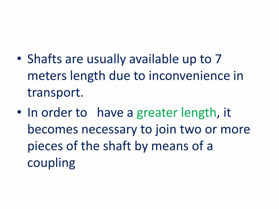
• Shafts are usually available up to 7 meters length due to inconvenience in transport.
• In order to have a greater length, it becomes necessary to join two or more pieces of the shaft by means of a coupling

• Shaft couplings are used in machinery for several purposes,
• 1.To provide for the connection of shafts of units that are manufactured separately such as a motor and generator and to provide for disconnection for repairs or alternations.
• 2.To provide for misalignment of the shafts or to introduce mechanical flexibility.
• 3.To reduce the transmission of shock loads from one shaft to another.
• 4.To introduce protection against overloads.
• 5.It should have no projecting parts

• Requirements of a Good Shaft Coupling
• 1.It should be easy to connect or disconnect.
• 2. It should transmit the full power from one shaft to the other shaft without losses.
• 3.It should hold the shafts in perfect alignment.
• 4.It should reduce the transmission of shock loads from one shaft to another shaft.
• 5.If should have no projecting parts.

Types of Shafts Couplings
• 1. Rigid coupling 2. Flexible coupling
1. Rigid coupling : It is used to connect two shafts which are perfectly aligned.
• types of rigid coupling are
• a)Sleeve or muff coupling.
• b)Clamp or split-muff or compression coupling,
• c)Flange coupling

• 2.Flexible coupling : It is used to connect two shafts having both lateral and angular misalignment.
• Types of flexible coupling are
• a)Bushed pin type coupling,
• b)Universal coupling, and
• c)Oldham coupling

a. Sleeve or Muff-coupling

• It is the simplest type of rigid coupling, made of cast iron.
• It consists of a hollow cylinder whose inner diameter is the same as that of the shaft (sleeve).
• It is fitted over the ends of the two shafts by means of a gib head key, as shown in Fig.
• The power is transmitted from one shaft to the other shaft by means of a key and a sleeve.
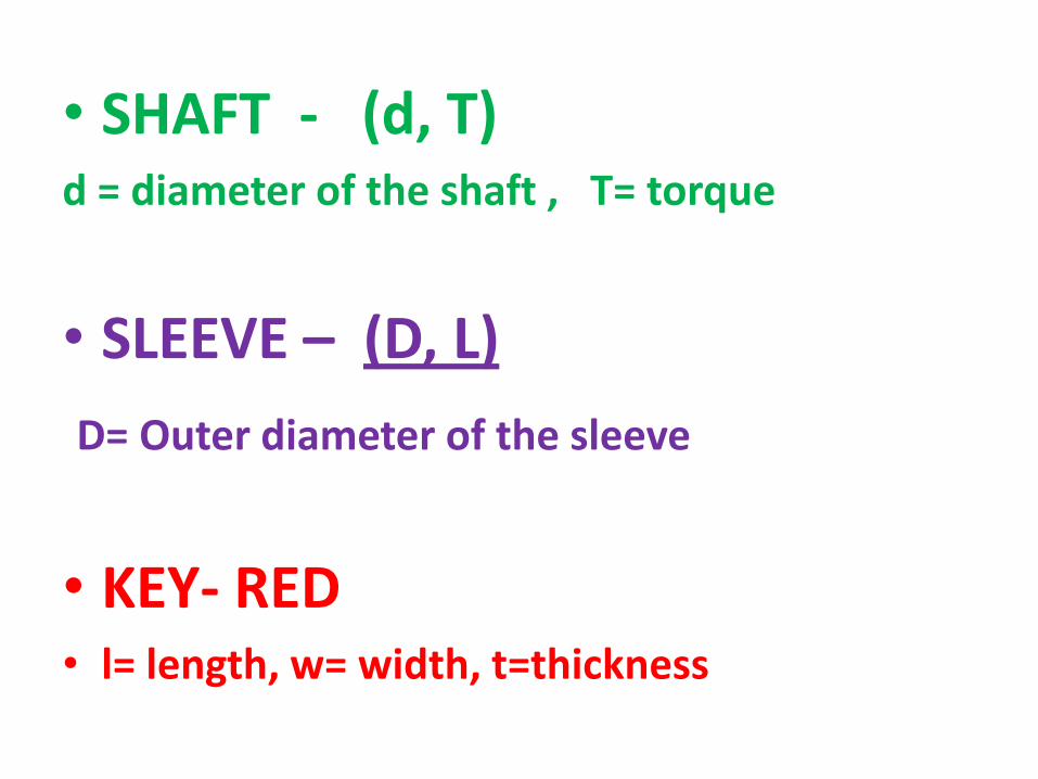
• SHAFT - (d, T)d = diameter of the shaft , T= torque
• SLEEVE – (D, L)
D= Outer diameter of the sleeve
• KEY- RED • l= length, w= width, t=thickness

1. Design for sleeve
• The usual proportions of a cast iron sleeve coupling
• Outer diameter of the sleeve, D =2d + 13 mm
• length of the sleeve, L=3.5d
Where d = diameter of the shaft
• The sleeve is designed by considering it as a hollow shaft.
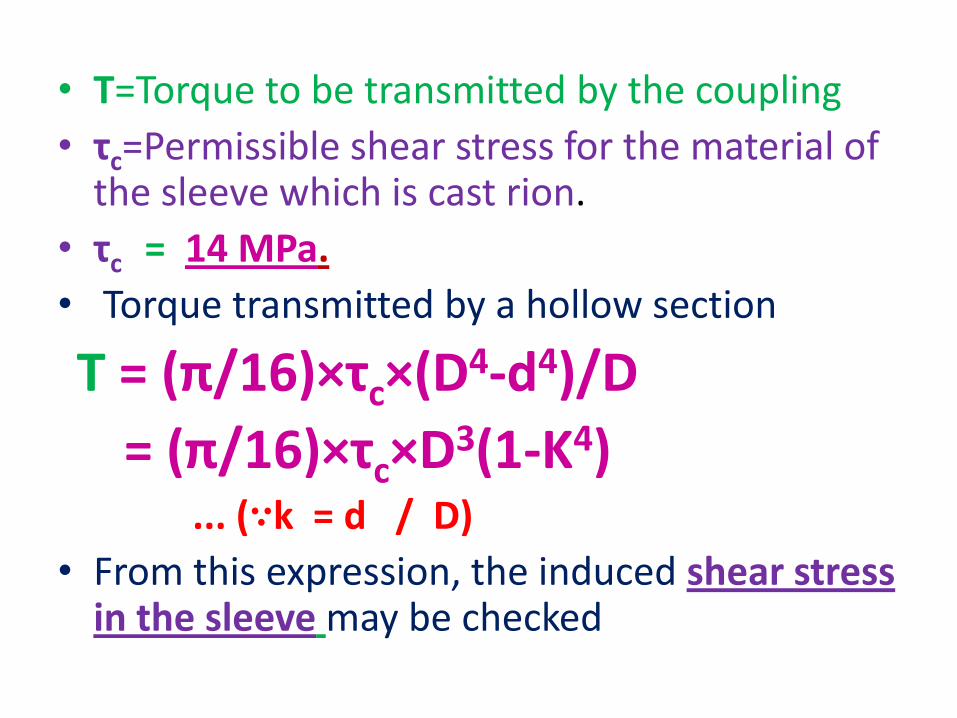
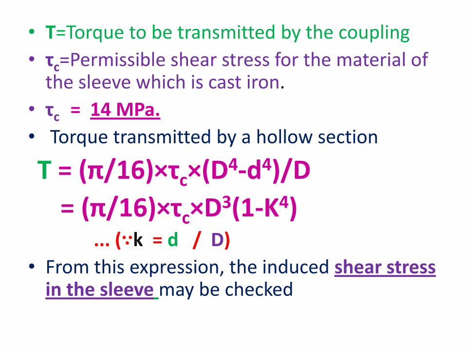
• T=Torque to be transmitted by the coupling
• τc=Permissible shear stress for the material of the sleeve which is cast rion.
• τc = 14 MPa.
• Torque transmitted by a hollow section
T = (π/16)×τc×(D4-d4)/D
= (π/16)×τc×D3(1-K4)... (∵k = d / D)
• From this expression, the induced shear stress in the sleeve may be checked
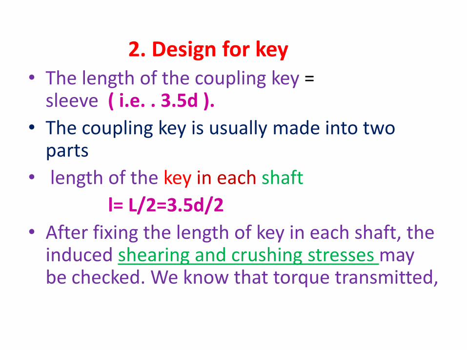
2. Design for key• The length of the coupling key = length of the
sleeve ( i.e. . 3.5d ).
• The coupling key is usually made into two parts
• length of the key in each shaft
l= L/2=3.5d/2
• After fixing the length of key in each shaft, the induced shearing and crushing stresses may be checked. We know that torque transmitted,

• T = l× w×τ ×(d /2) (Considering shearing of the key)
• T = l × t/2 × σC × (d /2) (Considering crushing of the key

b. Clamp or Compression Coupling

• the muff or sleeve is made into two halves and are bolted together.
• The halves of the muff are made of cast iron.
• The shaft ends are made to a butt each other
• a single key is fitted directly in the keyways of both the shafts.
• One-half of the muff is fixed from below and the other half is placed from above.
• Both the halves are held together by means of mild steel studs or bolts and nuts.
• The number of bolts may be two, four or six.
• The advantage of this coupling is that the position of the shafts need not be changed for assembling or disassembling of the couplings

1. Design of muff
• The usual proportions of a cast iron sleeve coupling
• Outer diameter of the sleeve, D =2d + 13 mm
• length of the sleeve, L=3.5d
Where d = diameter of the shaft
• The sleeve is designed by considering it as a hollow shaft.
• T=Torque to be transmitted by the coupling
• τc=Permissible shear stress for the material of the sleeve which is cast iron.
• τc = 14 MPa.
• Torque transmitted by a hollow section
T = (π/16)×τc×(D4-d4)/D
= (π/16)×τc×D3(1-K4)... (∵k = d / D)
• From this expression, the induced shear stress in the sleeve may be checked

2. Design for key
• The length of the coupling key = length of the sleeve ( i.e. . 3.5d ).
• The coupling key is usually made into two parts
• length of the key in each shaft
l= L/2=3.5d/2
• After fixing the length of key in each shaft, the induced shearing and crushing stresses may be checked. We know that torque transmitted

• T = l× w×τ ×(d /2) (Considering shearing of the key)
• T = l × t/2 × σC × (d /2) (Considering crushing of the key

3. Design of clamping bolts
• T =Torque transmited by the shaft,
• d =Diameter of shaft,
• d b=Root or effective diameter of bolt
• n=Number of bolts,
• σt =Permissible tensile stress for bolt material,
• µ=Coefficient of friction between the muff and shaft, and
• L=Length of muff.

• force exerted by each bolt (F) =(π/4) (d b2 ) σt
• Force exerted by the bolts on each side of the shaft (F)= (π/4) (d b
2 ) (σt )(n/2)
• (P )be the pressure on the shaft and the muff surface due to the force, then for uniform pressure distribution over the surface
• P=Force/Projected area
• P= (π/4) (d b2 ) (σt )(n/2)/(1/2)Ld
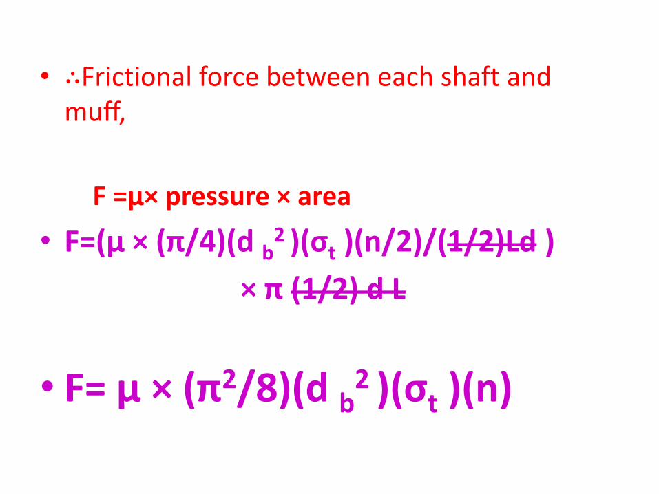
• ∴Frictional force between each shaft and muff,
F =µ× pressure × area
• F=(µ × (π/4)(d b2 )(σt )(n/2)/(1/2)Ld )
× π (1/2) d L
• F= µ × (π2/8)(d b2 )(σt )(n)
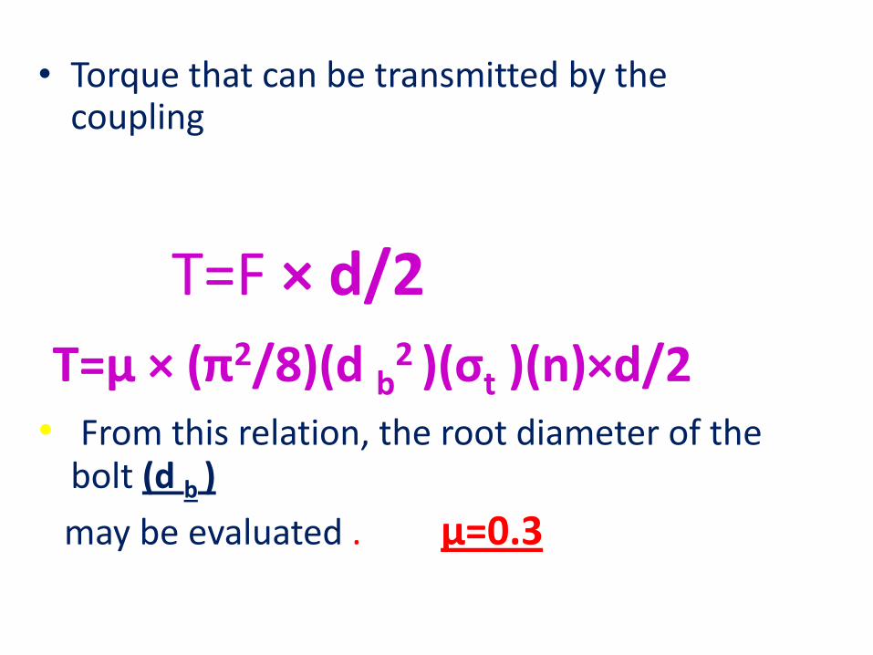
• Torque that can be transmitted by the coupling
T=F × d/2
T=µ × (π2/8)(d b2 )(σt )(n)×d/2
• From this relation, the root diameter of the bolt (d b )
may be evaluated . µ=0.3

c. Flange coupling
• A flange coupling usually applies to a coupling having two separate cast iron flanges.
• Each flange is mounted on the shaft end and keyed to it.
• The faces are turned up at right angle to the axis of the shaft
• Flange coupling are• 1.Unprotected type flange coupling• 2. Protected type flange coupling• 3. Marine type flange coupling

1.Unprotected type flange coupling

• In an unprotected type flange coupling each shaft is keyed to the boss of a flange with a counter sunk key and the flanges are coupled together by means of bolts.
• Generally, three, four or six bolts are used

Design of Unprotected type Flange Coupling
• The usual proportions for an unprotected type cast iron flange couplings
• d = diameter of the shaft or inner diameter of the hub • D= Outside diameter of hub D=2d• Length of hub, L= 1.5d• Pitch circle diameter of bolts, D1=3d• Outside diameter of flange,
D2= D1+ ( D1– D) = 2 D1– D= 4d• Thickness of flange tf =0.5d• Number of bolts =3, ford upto 40 mm
=4, for d upto 100 mm=6, for d upto 180 mm

• d =Diameter of shaft or inner diameter of hub,• τs =Allowable shear stress for shaft,
• D=Outer diameter of hub,• tf =Thickness of flange• τc=Allowable shear stress for the flange material
• d 1=Nominal or outside diameter of bolt,• D1 =Diameter of bolt circle,• n=Number of bolts,• τb= Allowable shear stress for bolt • σ cb,, =Allowable crushing stress for bolt
• τk= Allowable shear stress for key material • σ ck= key material
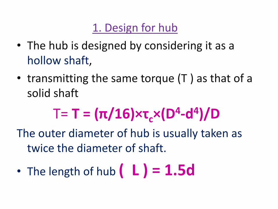
1. Design for hub
• The hub is designed by considering it as a hollow shaft,
• transmitting the same torque (T ) as that of a solid shaft
T= T = (π/16)×τc×(D4-d4)/DThe outer diameter of hub is usually taken as
twice the diameter of shaft.
• The length of hub ( L ) = 1.5d

2. Design for key
The material of key is usually the same as that of shaft. The length of key is taken equal to the length of hub
l=L
• T = l× w×τ ×(d /2) (Considering shearing of the key)
• T = l × t/2 × σC × (d /2) (Considering crushing of the key

3. Design for flange
The flange at the junction of the hub is under shear while transmitting the torque.
• T =Circumference of hub × Thickness of flange × Shear stress of flange × Radius of hub
• T= π D × tf × τc × D/2
T= π × tf × τc × D2/2The thickness of flange is usually taken as half the diameter of shaft

4. Design for bolts
• Load on each bolt (F)=
(π/4) (d 12 ) (τb)
• Total load on all the bolts (F) =
(π/4) (d 12 ) (τb)(n)
• The bolts are subjected to shear stress due to the torque transmitted
(T)= (π/4) (d 12 ) (τb)(n) (D1/2)
From this equation, the diameter of bolt (d 1 )may be obtained.

• We know that area resisting crushing of all the
bolts = n× d 1 × tf
• crushing strength of all the bolts
= n× d 1 × tf × σCb
• ∴Torque = n× d 1 × tf × σCb × (D1/2)
• From this equation, the induced crushing stress in the bolts may be checked

Protected type flange coupling

• the protruding bolts and nuts are protected by flanges on the two halves of the coupling, in order to avoid danger to the workman
(tp ) =0.25d
The design of unprotective type is same process of protective type
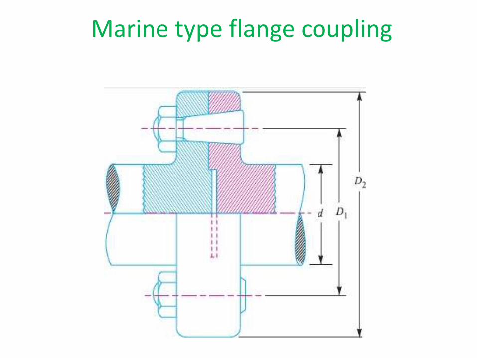
Marine type flange coupling

• In a marine type flange coupling, the flanges are forged integral with the shafts .
• The flanges are held together by means of tapered head less bolts.
• numbering from four to twelve depending upon the diameter of shaft.
• Shaft diameter No. of bolts• 35 to 55 4• 56 to 150 6 • 151 to 230 8• 231 to 390 10• Above 390 12

• The other proportions for the marine type
flange coupling
• Thickness of flange =d / 3
• Taper of bolt= 1 in 20 to 1 in 40
• Pitch circle diameter of bolts, D1= 1.6d
• Outside diameter of flange, D2= 2.2d

Bushed-pin Flexible Coupling

• is a modification of the rigid type of flange coupling.
• The coupling bolts are known as pins. The rubber or leather bushes are used over the pins.
• The two halves of the coupling are dissimilar in construction.
• A clearance of 5 mm is left between the face of the two halves of the coupling.

• the proportions of the rigid type flange coupling
• the bearing pressure on the rubber or leather bushes and it should not exceed 0.5 N/mm2
Pin and bush design
• l=Length of bush in the flange,
• d 2=Diameter of bush,
• pb=Bearing pressure on the bush or pin,
• n=Number of pins,
• D1=Diameter of pitch circle of the pins
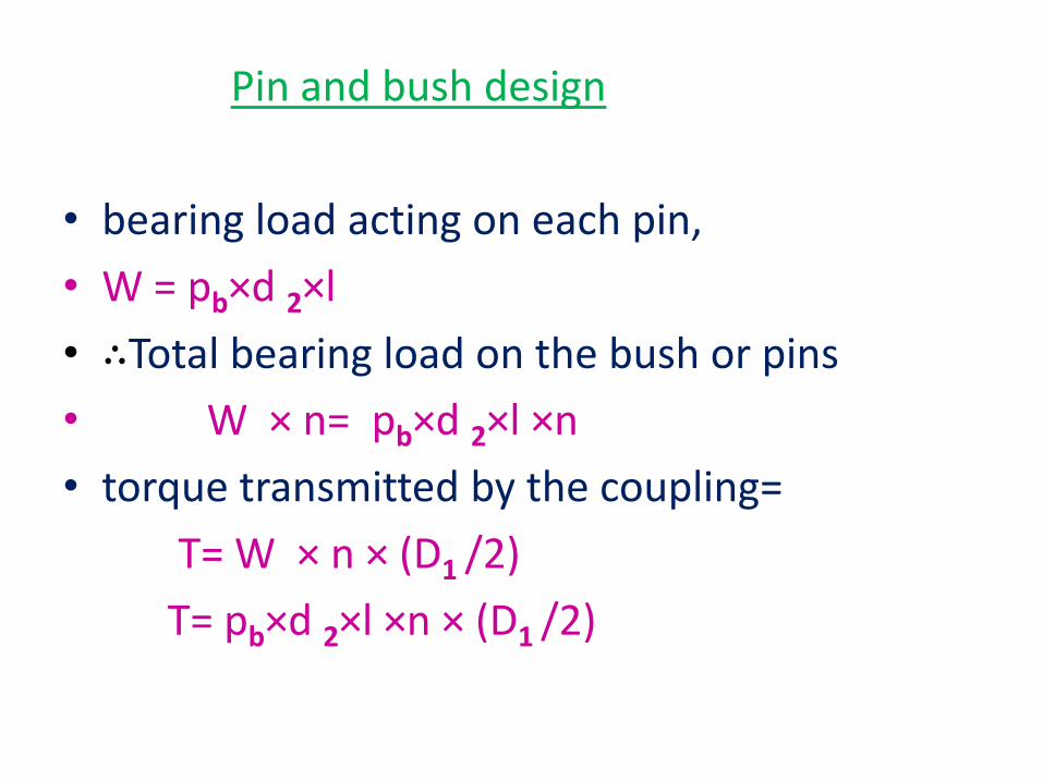
Pin and bush design
• bearing load acting on each pin,
• W = pb×d 2×l
• ∴Total bearing load on the bush or pins
• W × n= pb×d 2×l ×n
• torque transmitted by the coupling=
T= W × n × (D1 /2)
T= pb×d 2×l ×n × (D1 /2)
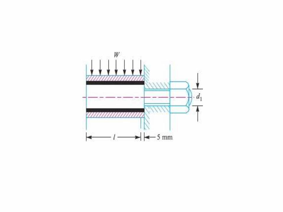

• Direct shear stress due to pure torsion in the coupling halve
• τ=W/[ (π/4) (d 12 )]
• maximum bending moment on the pin
• M =W (l/2 +5mm)
• bending stress
σ= M / Z
= W (l/2 +5mm)/ (π/32) (d 13)

• Maximum principal stress
= 1/2[σ +(σ+4τ2 ) 1/2]
• maximum shear stress on the pin
= 1/2(σ+4τ2 ) 1/2
• The value of maximum principal stress varies from 28 to 42 MPa