design of the mroi delay line optical path compensator
TRANSCRIPT

Design of the MROI delay line optical path compensator
M. Fisher, R.C. Boysen, D.F. Buscher, C.A. Haniff, E.B. Seneta, X. Sun, D.M.A. Wilson and J.S. Young
University of Cambridge, Cavendish Astrophysics Group, Cambridge CB3 0HE, UK
Email: [email protected] The delay lines for the Magdalena Ridge Observatory Interferometer in New Mexico are required to provide up to 380m optical path delay with an OPD jitter of better than 15nm, in vacuum, using a single adjustable stroke. In order to meet these demanding requirements in a cost-effective manner a unique combination of techniques has been used in the design and construction of the delay line trolley which operates continuously within 190m of evacuated pipe. These features include contactless delivery of power and control signals, active control of the cat's eye optics and the use of composite materials to achieve good thermal stability. A full-size prototype trolley has been built and fully tested and the first production trolley is under construction. We describe the system's key design features and review the construction and alignment of the delay line trolley. Results obtained with the trolley operating in an evacuated 20m-long test rig under the full range of conditions required for successful astronomical observations are presented. An OPD jitter of typically 10nm is achieved over the total tracking velocity range from 0 to 15mm/s. Keywords: interferometer, delay line, optical path compensator, cat’s eye, OPD
1. INTRODUCTION The overall design of the Magdalena Ridge Observatory Interferometer is described in a paper presented in this conference1. The intention of this paper is to present a more detailed account of the design of the delay line optical path compensator and in particular the trolley which carries the reflective optics. An overview of the design and a statement of the performance requirements have been presented at a previous conference2 but the most important performance requirements are re-stated here: (i) the slew speed [of the trolley] must allow 15m of physical travel of the delay line trolley in less than 30 seconds, and travel over the full delay line stroke (190m) in less than 5 minutes; (ii) sidereal tracking must be possible at rates of physical travel of the delay line carriages of up to 15mm/s with a jitter of no more than λ/40 RMS over a time period of twice the coherence time, t0. For atmospheric conditions appropriate for the MROI site, this corresponds to a maximum jitter of 15nm on 10ms timescales (for observations at 0.6 μm), of 41nm on 35ms timescales (for observations at 1.65 μm), and 55nm on 50ms timescales (for observations at 2.2 μm). A prototype trolley has been built and has passed final design acceptance tests in a 20m prototype delay line installed at the COAST facility near Cambridge. The first production model is under construction and is due to be delivered to the MROI site for acceptance in September.
2. SYSTEM COMPONENTS To operate as a system each of the delay lines installed at the Magdalena Ridge will incorporate a number of individual subsystems under software control, the details of which have been presented previously3. The relative physical locations of these subsystems are shown schematically in Figure 1 and described briefly as follows: Delay Line Trolley: This consists of a cylindrical “carriage” which is about 8 feet long and 14 inches in diameter, supporting and enclosing a cylindrical cat’s eye retro-reflector. The trolley has a pair of wheels at each end which are angled at 45º to the vertical so that it can move inside a circular vacuum pipe which acts as a guide.

Delay Line Pipe: The pipe is composed of up to 52 twelve-foot sections of standard industrial ½ inch wall 16 inch O.D. aluminium extrusion placed end to end to form a 190m continuous tube. The pipe sections are joined accurately using dowels at positions where the trolley wheels would cross in order to minimize disturbances to the trolley as it traverses the join. The join is held together by tie-bars and sealed by a flexible rubber tube. Each join is supported in a cradle mounted on flexure legs to accommodate thermal expansion with respect to the concrete floor. The delay line pipe is anchored close to the beam combining area. The vacuum required in the pipe is approximately 1 mbar; this minimizes dispersion of the light beams and internal ‘seeing’ while still retaining good thermal conduction to allow heat generated within the trolley to be transferred to the pipe. Laser Metrology System: The laser metrology system is mounted on an optical bench in the beam combining area located at one end of the delay line (the ‘near end’) and is used to measure the position of the cat’s eye. The laser beam is passed through a beam expander before entering the near end of the vacuum pipe. The beam is reflected from the cat's eye and returns out of the near end of the pipe, whereupon it is re-compressed before being directed back to the metrology interferometer optics where it is combined with the unexpanded outgoing laser beam. A single VME system handles up to ten channels of metrology, computing position errors and transmitting them to the trolley cat’s eye to produce the required correction. A datum sensor is positioned on each delay line so that the trolley can be referenced to a known position which is relatively stable throughout the night and from night to night. Shear Sensor System: This consists of a computer and a web camera which samples the returning metrology beam from the trolley and produces a centroid. The centroid is compared to a reference point and the error transmitted to the trolley. Lateral deviations of the delay line, and hence the trolley within it, cause the metrology beam entering the cat’s eye to be returned with twice the deviation. If shear is not corrected the metrology system would fail because the reference and return beams would not overlap accurately in the metrology interferometer optics. The science beam would also be affected in a similar way, causing loss of fringe visibility as well as loss of light when combined with beams from the other delay lines. To ensure this does not happen, the error sent to the trolley commands the flat secondary mirror of the cat’s eye to tip/tilt to correct the deviation of the return beam. The shear of the science beam is thus also corrected. It is this feature of the system that negates the necessity for precision rails needing frequent re-alignment and allows relatively cheap industrial components to be used. Communications and Power: The very long length of the delay line presents substantial challenges in providing communication and power to the trolley. The problems of trailing cables are overcome by the adoption of an inductive power supply to deliver electrical power to the trolley, and RF transmission, using the pipe as a waveguide, to deliver communications signals. Inductive power is supplied via a wire lying along the bottom of the vacuum pipe. The wire passes through a long thin transformer mounted underneath the trolley which inductively couples high-frequency electrical power from the wire to rectification and smoothing circuits on board the trolley. Thus as the trolley moves along the pipe it picks up the wire which then has only to slide the length of the transformer before dropping back to the pipe. Two RF transmission systems are employed in communicating with the trolley; one for network communications to pass commands, status and telemetry, and another to pass an analogue position correction signal with low latency from the metrology system to the cat’s eye. Workstation: A workstation coordinates the activity of all delay lines, computes the trajectories for each trolley and sends them to the VME computer which then generates the position demands for each channel of metrology. In stand-alone mode the workstation is also used to generate log files of commands, status and telemetry which are automatically sent from each subsystem. These log files are saved as FITS binary tables. Whenever the workstation is under control of the Interferometer Supervisory System (ISS) it translates high level commands into subsystem commands and logging is handled by the ISS. A Matlab-based GUI is used for analysis and presentation of delay line system performance.

Figure 1. Schematic of the delay line subsystems. Metrology system components are shown in grey.
3. TROLLEY MECHANICAL DESIGN
3.1. Trolley The term trolley refers to the complete assembly which runs on wheels inside the delay line pipe. The trolley comprises two major components: the cat’s eye assembly and the carriage assembly. A cut-away view of the trolley inside the pipe is shown in Figure 2. Here three cylindrical structures are clearly shown: the outer cylinder (grey) is the delay line pipe, next is the cylinder of the trolley itself (yellow), and innermost is the black carbon fibre tube of the cat’s eye. This is the most compact design feasible and allows ten delay line pipes to be fitted side-by side on a concrete floor slab only twenty feet across. The carriage is supported and guided in the pipe by four wheels having resilient tyres and which contact the inner wall of the pipe orthogonally. This four point kinematic contact keeps the carriage axially aligned with the pipe, constraining it in four degrees of freedom and thus requiring only piston motion and roll about its axis to be controlled. The carriage also houses the cat’s eye, motor drive and other components and electronics that are required to control the complete assembly. The cat’s eye assembly is a tube housing the optical components and is mounted onto the carriage via flexure legs so that it is free to move along its axis with virtually no friction. The carriage is actually two halves of a tube joined together along its length. The upper half is the carriage top shell and the lower half is the carriage chassis. This structure allows the cat’s eye and other components to be easily mounted on the chassis and yet retains much of the rigidity of the original tube when re-assembled. The design of the major components and sub-assemblies is presented in more detail in the following subsections.

Figure 2. Two views of the trolley mounted inside the delay line pipe. The top ‘cut-away’ view shows the cylindrical cat’s eye tube within the trolley shell inside the delay line pipe. The drive and control electronics are situated to the rear of the bulkhead, behind the cat’s eye. The lower translucent view shows the optical beam paths, the optical wedges on the front plate and the inductive power transformer more clearly.
3.1.1. Trolley shell The carriage is manufactured from a single aluminium tube approximately 8 feet long with an O.D. of 14 inches and a wall thickness of 0.25 inches. The tube is machined to length and is then specially prepared for splitting lengthways into two halves which are then rejoined with accurately machined joining strips. This method of construction allows complex machining work to be done on the bottom half of the tube (the chassis) while maintaining the necessary accuracy and as much stiffness as possible when the two halves of the tube are joined again. To fulfil requirements for alignment and to strengthen the shell, especially where a slot for the transformer must be cut, the chassis has segments of aluminium alloy fixed to the bottom and then machined where necessary to provide accurate seat locations with respect to an established central axis. This also ensures that the axes of the wheels intersect at the correct locations and the trolley sits at the correct height within the delay line pipe. At a further stage, holes are machined in the chassis for the wheels and a longitudinal slot is milled to accommodate the linear transformer of the inductive power transfer system. A diagram of the trolley chassis is shown in Figure 3. The trolley top shell is one piece, carries no parts and is fixed to the bottom shell along the sides, at the position of the voice coil bulkhead and also through the end plates at each end of the trolley. Bolt locations protrude through the top of the shell to allow a lifting bar to be fitted (about the centre of gravity) for handling the trolley.

Figure 3. The trolley chassis has four separate segments glued into the half-cylinder. These are then machined in one operation to
provide accurate location and alignment of the wheels and the cat’s eye flexure mounts. Gaps between the segments are necessary to allow for the cat’s eye primary mirror cell and secondary mirror structure.
3.1.2. Chassis components The important components mounted on the chassis are the front wheel assembly, the rear wheel assembly (including drive and steering), the front and rear ‘wishbone’ flexure legs of the cat’s eye and the bulkhead to which the voice coil is mounted. These components are now briefly described. The front wheel assembly and front cat’s eye flexure legs are both fitted to the front chassis segment. The arrangement is shown in Figure 4. Wheels: The front and rear wheel assemblies are constructed and mounted so that they contact the pipe at the same radial position and with parallel alignment. The front wheels are limited to 75mm in diameter by the need for clear apertures for the light beams, but the rear wheels are 150mm in diameter as the centre of gravity of the trolley is nearer this end and larger wheels traverse any small steps in pipe joints more easily. The wheels have a 25mm wide solid polyurethane tyre machined to provide a profile with a curvature slightly smaller than that of the pipe. Cat’s eye flexures: It is important that the front and rear seating of the cat’s eye pivot flexure mounts are aligned and co-planar to prevent distortion of the flexures leading to poorer performance and a limited life. The flexure pivot for attaching the front cat’s eye legs to the chassis is necessarily composed of two separate L-shaped blocks which bolt down on to the accurately machined faces of the front chassis segment. The tolerances on the machined components and surfaces are such that any slight misalignment which would produce an over-constraint on the flexure pivots is removed by tightening the upper flexure pivot blocks to the cat’s eye secondary support ring after the cat’s eye assembly is seated in the chassis. The rear cat’s eye flexure legs are in one piece and pivot on a seat which is aligned by and attached to the fourth chassis segment close to the voice coil bulkhead. The flexure pivots are ‘C-flex’ rotary flexures which are effectively frictionless bearings. Bulkhead: The trolley bulkhead, shown in Figure 5, is a circular plate machined so as to fit in the slot of the rear segment of the chassis where it is attached. It has a central boss to locate the voice coil and radial ribs to provide axial stiffness. The outer edge of the plate is bolted to the trolley chassis and also to the trolley top-shell using blocks which can be set to conform to the local non-circularity of the trolley shell. The bulkhead plate also serves as a stiff mounting location for a Micro-Epsilon U15 eddy-current sensor that measures the differential position between cat’s eye and trolley. It is mounted on a cylindrical boss projecting from the bulkhead plate towards the mirror cell which is also the target material. Holes in the bulkhead plate allow two steel rods projecting from the cat’s eye to pass through. Each rod is arranged with hard stops preceded by thick washers of resilient damping material to provide firm mechanical ‘bump’ stops which limit the motion of the cat’s eye to approximately ±3mm.

Secondary structure
Secondary mirror
Focus motor
Trolley chassis
Cat’s eye
Front wheel assembly
Figure 4. View of the front of the trolley chassis. Note the front wheel arrangement, the front flexure leg of the cat's eye and the secondary mirror support structure with apertures for the science and metrology beams.
Figure 5. The trolley bulkhead, primary mirror cell, voice coil and rear flexure leg. The differential sensor, mounted near the top, measures the distance between the primary mirror cell and the voice coil bulkhead. The magnet of the voice coil is attached to the primary mirror cell. Mechanical stops fixed to the primary mirror cell but passing through the bulkhead plate limit the motion of the cat’s eye. The rear flexure leg is connected to pivot blocks on the primary mirror cell and on the pivot base.

3.1.3. Drive and steering assembly The drive and steering functions are assembled onto one block which fits into the machined slot of the rear segment of the trolley chassis to maintain alignment of the wheels. The assembly, shown in Figure 6, consists of a triangular frame onto which a motor plate and steering plate are bolted. Drive: The trolley drive consists of a Maxon EC60 brushless motor, with integral Hall sensors and a high-resolution incremental encoder, coupled to a Spiradrive right-angle output shaft gearbox with a lapped gear-set for smooth running and providing a 10.25:1 gear reduction. This arrangement has the advantage that it can be back-driven. Steering: Trolley roll (rotation about the axis of the cylinder) is made inherently stable by locating the trolley centre of gravity a little below the geometric axis. However, greater accuracy is required because the axes of the secondary tip/tilt stage must remain in reasonable alignment to the beam shear sensor and the trolley wheels must follow relatively narrow track zones to cross the pipe joints where the internal surfaces are aligned. A steering servo is therefore required to counteract forces from wheel misalignment, static imbalance and pipe surface conditions, that produce roll. Steering is accomplished by deviating the axis of the un-driven rear wheel by a very small amount, according to the roll of the trolley which is measured by an on-board tilt sensor. A detailed view of the trolley steering mechanism is shown in the right-hand diagram of Figure 6. The trolley wheel is mounted to a king-pin which is mounted on flexure pivots, similar to those used for the cat’s eye flexures, and set into a frame attached to the underneath of the steering sub-plate. The pivots allow the wheel to be tilted about an axis orthogonal to its axle, parallel to the sub-plate but offset from the point of contact of the wheel with the pipe wall. The steering arm attached to the king-pin is connected through an adjustable link to an eccentric bearing on the shaft of the steering motor. The eccentricity of the bearing is chosen such that a complete revolution of the motor produces a ±1° change of steering angle. The steering motor is a stepper motor with sufficient un-powered holding torque to resist the torque on the offset king-pin when the trolley moves. The motor is magnetically coupled to a rotary encoder to provide absolute steering position. This design results in very low backlash in the steering chain and maintains trolley roll angle to ±5mrad which corresponds to ±1mm at the wall of the delay line pipe. Steering power is consumed only when an (infrequent) steering correction is required.
Figure 6. Two views of the drive and steering assembly. The drive motor is coupled to a ‘Spiradrive’ gearbox with a right-angle output shaft onto which the drive wheel is attached using a collet. The steering motor is coupled by eccentric cam to a link connected to the king-pin plate (visible in RH picture) onto which the steered wheel is bolted. The king-pin plate is pivoted at each end using c-flex bearings. The cam is designed to give a steering angle of up to ±1º.

3.1.4. Electronics assemblies Electronics and control on board the trolley consist of a number of boards and modules clustered about a compact stack of microprocessor and interface components. These are mounted in a compartment formed between the voice coil bulkhead and the back plate of the carriage. An important design consideration, apart from compactness, is to mount certain modules or boards in a way that heat can easily be conducted to the carriage shell and then dissipated to the surrounding delay line pipe. At a pressure of 1mBar the thermal conductivity of the air is almost the same as at atmospheric pressure and so the significant heat transfer conditions are those of conduction and radiation. Both of these are served by distributing heat over a reasonably large area at the rear end of the trolley. The microprocessor stack contains all the circuit boards that are required to be connected to the trolley CPU through the PC104 bus. Break-out boards are mounted on either side of the stack for convenience in interfacing signals from dispersed external sources and for ease of monitoring when servicing the trolley. The stack is mounted in a T-shaped frame at the rear of the trolley (see Figure 7). The frame is made from brass and is thermally coupled to the rear chassis segment at the base of the ‘T’ and to the chassis shell at either side of the ‘T’. There are two main heat sources within the stack: a PMAC motion controller, dissipating about 6W, and the stack inverter power supply with similar dissipation. Heat from the circuits on the PMAC board is coupled through a thin conformal heat transfer layer to a specially machined cover plate connected to the T-frame. The PSU heat sink is coupled to the side of the T-frame using a similar method. This allows the whole stack to be removed without compromising the thermal connection. The T-frame also accommodates other modules and boards as well as the inclinometer, used to detect the roll angle of the trolley. A ‘shelf’ mounted on brackets further forward, directly over the drive and steering module, accommodates the differential position sensor electronics module, the voice coil amplifier module and the focus driver and transducer interface modules.
Figure 7. The compact arrangement of trolley electronics circuit boards and modules is designed to conduct heat into the trolley shell,
particularly from the PC104 stack mounted in the T-frame. Thermal tape and conformal layers are used to improve conductivity.

3.1.5. Inductive power transformer The transformer is mounted (partially in a groove) on the underside of the trolley and consists of a series of ~90 ferrite cores threaded on to a brass tube attached to the underside of the trolley. The brass tube serves both as a mechanical support and a single-turn secondary winding. The induction cable, which is laid in the bottom of the delay line pipe, is picked up by guides at either end of the trolley and is passed through the transformer. As the trolley moves, the induction cable is lifted up a short distance, passes through the brass tube which supports it with very little friction and is deposited again on the pipe. The transformer is held in a clamp at each end, which also serves as the electrical connection, and there are two electrically isolated intermediate supports.
3.1.6. Trolley end-plates The front end plate, shown in Figure 8, contains apertures for the science and metrology beams. Mounted over the metrology beam apertures are two shallow-angle matched optical wedges to deflect the metrology laser beam so that its light does not come to a focus on the secondary mirror at exactly the same place as the science beam and so risk being scattered into it. The rear end plate, shown in Figure 9 supports a stub aerial for the low-latency RF link and a biquad (bow-tie) antenna aerial for the wi-fi network and is covered with ‘Echosorb’ material to diminish reflections of the RF waves travelling down the delay line pipe. The Echosorb looks more like an infinite tube rather than a ground plane at 2.4GHz (wi-fi), while the metal plate behind it looks like a ground plane at 900MHz. A 120mm x 120mm aperture is cut in the Echosorb material to provide a ground plane for the bow-tie aerial. Magnetic limit switches are mounted on each end plate and, at the bottom, a ‘fairlead’ is fitted to guide the inductive power cable into the transformer.
Figure 8. Front end plate showing science beam apertures,
metrology beam apertures with wedges, limit switches mounted near the top and a 'fairlead' to pick up and guide the
inductive power cable into the transformer.
Figure 9. Rear end plate with bow-tie wi-fi aerial, low-latency
stub aerial, limit switches near the top and 'fairlead’ for the inductive power cable at the bottom.
3.2. Cat’s eye assembly The cat's eye has two optical components, a 12 inch ~f/4 parabolic primary mirror and a small flat secondary mirror located at its focus. This forms a relatively benign optical system that can tolerate tilts of the secondary mirror without adversely affecting wave-front quality and hence visibility loss (up to 0.5% at maximum tilt). This arrangement enables tip-tilt correction of lateral deviations of trolley due to non-straightness of the delay line pipe of up to ±5mm. A cat’s eye has the property that the output beam is returned parallel to the input beam irrespective of the incident angle. Therefore any tilt of the trolley with respect to the incident light beams due to deviations of the pipe will have no effect on the returned beams. Hence a collimated beam of light striking the primary mirror is brought to a focus on the secondary mirror, reflected back to the primary mirror, and returned parallel to its original direction. A shear of the trolley with respect to the incoming beam will produce a shear of the return beam by twice as much. The shear of the return beam can
be corrected by tilting the secondary mirror. The primary and secondary mirrors are mounted in structures which are attached to the ends of a very stiff tube. These structures have support points for the flexural pivots which attach the cat’s eye via the flexure legs to the trolley chassis.
3.2.1. Cat’s eye tube The cat’s eye tube is formed from a very rigid but light carbon fibre composite tube which is specially designed to achieve high axial stiffness with low thermal expansion coefficient. Accurately machined aluminium end rings are glued on to the ends of the tube, using a jig, so that the faces are parallel and normal to the axis of the tube and are not rotated with respect to each other. The mass of the cat’s eye tube and end rings is minimized while maintaining sufficient stiffness with the aim of keeping the first axial resonance of the assembly above 1200 Hz. The carbon fibre tube also provides significant damping which helps to maximize the bandwidth of the cat’s eye servo.
3.2.2. Primary mirror cell The primary mirror is mounted in a substantial aluminium alloy cell which is composed of a back plate and two half shells which also attach to the carbon fibre tube end ring. This construction allows the top wall of the cell to be removed so that the mirror may be inserted or lifted out using a circumferential strap. The mirror cell, shown in Figure 5, incorporates two radial defining adjuster screws in the lower half-shell and a pre-loading screw in the upper half. This arrangement restrains and locates the primary mirror on the axis of the cat’s eye. The primary mirror is manufactured with a 3mm wide chamfer on its front outside diameter edge, normal to its optical axis to within 1 arc-minute, and this is preloaded onto pads glued to the cat’s eye end ring using three spring-loaded adjusters mounted in the rear face of the mirror cell. This arrangement defines the axial position of the primary and aligns its optical axis to be parallel with the cat’s eye tube. Hence the only adjustment necessary to align the primary to the cat’s eye axis is to set the radial defining screws and adjust the thickness of the end ring pads. This is done once, when the cat’s eye is assembled and aligned on an optical bench. The back plate of the mirror cell contains a central boss into which the magnet of the voice coil is located. There are two steel rods on either side of the boss which pass through the bulkhead plate to limit the travel of the cat’s eye. Also on the same horizontal axis are the two flexure pivot blocks for the upper part of the flexure leg.
3.2.3. Secondary mirror and support structure The secondary mirror support structure (refer to Figure 4) is a ring with vanes supporting a small central region. It is manufactured from one piece to provide axial stiffness and symmetry and because of the limited distance between the incoming and outgoing science beams. The narrow centre-piece is machined hollow to accept the secondary mirror tip-tilt stage, a focus mechanism with drive and an absolute encoder. A face-plate is glued to the support structure to provide damping of the first modes of vibration of the ring which helps to increase the servo bandwidth and hence the disturbance rejection of the system. The secondary mirror is glued directly to the face-plate of a commercial Piezosystem Jena PSH-10 tip-tilt actuator. This actuator can tilt by up to at least ±4mrad in two orthogonal axes to compensate for lateral shear of the trolley of at least ±5.2mm with respect to the incident light beams due to deviations of the delay line pipe. The actuator body is held in a frame supported by flexures which allow a piston movement of up to 1mm using a linear piezo-motor. This arrangement provides focusing for the cat’s eye with a resolution of better than 1μm while focus position is provided by a non-contact type encoder with local repeatability of better than of ±1μm. The focal length of the primary mirror is accurately known and so it is possible to ensure that the secondary focus stage can be placed within ±0.25mm of the actual focus. The requirement on focus stability of the cat’s eye is ±5μm and the expected diurnal variation of temperature inside the long building which houses the delay lines is approximately 2ºC. Since the overall CTE of the cat’s eye primary/secondary separation is <2μmC-1 it will not be necessary to adjust the focus during the night.
3.2.4. Optical alignment The optics of the cat’s eye are aligned using a theodolite with auto-reflect capability. The primary mirror optical axis is known with sufficient precision with respect to its centre bore that a transparent target can be set on it and on the centre bore of the mirror cell. This allows the radial position of the primary to be set. A special jig with tip and tilt adjustment is used to centre and hold the secondary mirror just in front but clear of the tip-tilt stage. The mirror is adjusted in tip and tilt to set it normal to the optical axis using the theodolite in auto-collimation. The tip-tilt stage is then brought close to the back of the secondary mirror using the focus drive and glued with three small beads of epoxy. This procedure ensures

that tolerance build-up in the structure and any wedge in the secondary mirror is accounted for and that the tip-tilt device operates about the centre of its range. The primary mirror is then adjusted in tip and tilt so that the auto-reflect of an internal target imaged by the primary is coincident with the axis of the cat’s eye.
4. TROLLEY ELECTRONICS AND COMPUTING The delay line trolley comprises many electronic subsystems. These include a computer and motion controller, onboard actuators, motors and sensors. These are controlled to provide the required functionality.
4.1. Trolley control A schematic of the on-board electronics is shown in Figure 10. The core components are a Central Processing Unit (CPU), a Programmable Multi-Axis Controller (PMAC), two analog input/output boards and an automotive inverter power supply. They are connected via a PC104 bus and are mechanically stacked together. Overall control of the trolley is imposed by the CPU, which communicates with the other core components via the PC104 bus and with the wi-fi module via ethernet. Control of the steering and drive servos is delegated to two channels of the PMAC. Two analogue I/O boards together with associated break-out boards are used to interface with the remaining subsystems of the trolley. The PMAC also accepts inputs from the trolley limit switches to limit or stop the drive motor when the trolley is close to the ends of the delay line. The cat’s eye drive preamplifier accepts a position error signal from the metrology system via the analog radio link and conditions it to drive the voice coil amplifier which in turn moves the cat’s eye to minimise the tracking error. The differential position sensor measures the position of the cat’s eye with respect to the trolley and is used in ‘local’ servo loops and monitored by the CPU. The CPU can adjust various pre-amplifier gains and compensation by setting the values of onboard digital resistors connected to its I2C bus.
Figure 10. Schematic of the on-board trolley electronics which are centred about the PC104 stack.

4.2. Sensing and telemetry The trolley is designed to relay substantial status and telemetry to an archive to assist in performance measurement and de-bugging of potential problems. The majority of the interfacing of on-board signals is handled by the two Analogue I/O boards. Each board has 16 analogue inputs, each of which is sampled at 5 kHz in turn by a single onboard 16 bit analog to digital converter and hence the inputs are not sampled simultaneously. This phase lag of ~9μs between channels is allowed for in the messaging protocol used to transmit trolley telemetry by wi-fi to the controlling workstation. Time stamping is used and there is a 512 byte sample buffer on each board that temporarily stores the data before it is read by the CPU. The buffering is sufficient to allow a program running within a non-real-time operating system to capture all the data. Each board is also equipped with 12-bit digital to analogue converters which drive the HV amplifiers for the tip-tilt stage and the focus actuator. The analogue boards are used for monitoring several of the cat’s eye preamplifier signals, some trolley drive amplifier signals, supply voltages, and sensors such as focus, trolley roll, thermometers and accelerometers. A digital channel is used to set the mode of the cat’s eye coil preamplifier to either “track” or “slew” (see below).
4.3. Servo loops There are two modes in which the trolley operates: tracking mode, in which the trolley moves at up to 15mm/s to compensate the optical path, and slew mode when the trolley is re-positioned along the delay line at speeds of up to 0.7m/s. In tracking mode the metrology loop controls the cat’s eye while the workstation issues a velocity trajectory command to the trolley. In slew mode the differential position sensor signal is used to hold the cat’s eye firmly in the centre of its range with respect to the trolley. Five servo loops are involved in providing track and slew functions; these are depicted in Figure 11 and described below.
Figure 11 Trolley servo loops. The trolley and cat’s eye (shown in green) is controlled using five servo loops: a ‘local velocity loop’ is closed about the PMAC motion controller; a ‘roll loop’ is closed about the tilt sensor and the steering mechanism; the ‘differential position loop’ provides several forms of closed loop feedback, depending on whether the trolley is in ‘slew’ or ‘track’ mode; the shear loop is closed about the shear camera (which measures the metrology beam position) and the tip-tilt secondary mirror; and the ‘metrology loop’ which measures the position of the cats eye is closed about the VME system and the cat’s eye voice coil.

4.3.1. Cat’s eye servo The cat’s eye servo loop is closed by the metrology system. This samples the cat’s eye position at 5kHz and supplies an analogue error signal with very low latency, of order 40μsec, to the trolley via the low latency radio link. In track mode this signal is compensated and amplified, providing a drive current to the cat’s eye voice coil. To maximize the rejection of disturbances and thereby minimize the jitter in the optical path difference (OPD) four important design conditions are employed: (i) the flexure legs supporting the cat’s eye should be kept vertical while tracking; (ii) the cat’s eye rigid body natural frequency should be very low; (iii) friction and viscous coupling between cat’s eye and trolley should be minimized and (iv) the first eigenfrequency of the cat’s eye primary/secondary separation should be very high. The techniques employed to realize these conditions are as follows: Vertical flexure legs: In track mode the differential position sensor signal is used to modify the trolley velocity such that the trolley moves to centre itself under the cat’s eye and thus keep the flexure legs vertical. Cat’s eye frequency: This frequency is determined by the mass of the cat’s eye and the stiffness of the flexures; the lower this frequency, the better is the disturbance rejection of the cat’s eye servo. The actual stiffness of the flexures is electronically modified using a small amount of feedback from the differential position sensor. In this design the flexure stiffness is insufficient to hold the cat’s eye upright and it acts like an inverted pendulum. Positive feedback is used to produce an apparent natural frequency of approximately 0.25Hz. Thus, in combination with very low damping between cat’s eye and trolley, a disturbance rejection in excess of 80dB from DC to 0.25Hz is obtained which then decreases at a rate of -40dB per decade consistent with a second order mass-spring-damper arrangement. Friction/viscous coupling: Friction can come from cables which, although looped onto the cat’s eye, may still cause frictional damping through twisting. However, most of the damping between cat’s eye and trolley comes from eddy current losses in the voice coil which has an aluminium former. This is reduced by using a small amount of velocity feedback from the differential sensor. Cat’s eye eigenfrequency: For our design this frequency is limited by the tip-tilt stage and focusing arrangement. The first piston mode of the assembled carbon fibre tube is of order 1900Hz and is well damped. The first piston mode of the secondary mirror support structure is approximately 1300Hz, however there are ‘hoop’ resonant modes of ~870Hz in the ring of the structure. These produces a small amount of piston of the central portion holding the tip-tilt stage but the resonance is damped significantly by the composite faceplate that is glued to the structure. The cat’s eye servo and its mode switching are implemented in the voice coil preamplifier. Appropriate gain and phase compensation is applied according to the mode in which the trolley is operating. Adjustment of gain and phase is made possible using ‘digi-pots’ which are set using the I2C bus from the local CPU. The metrology input is passed through a notch filter, set so as to further suppress the first mode of the secondary structure, and then forwarded to an adjustable phase lead stage followed by a gain and low pass filter stage. The differential sensor signal is handled in a similar fashion except there is no need for a notch filter stage. These compensated signals are switched to a summing amplifier depending on the operating mode of the trolley. Apart from providing position and velocity feedback, the differential position sensor is also used to provide electronic limiting of the displacement of the cat’s eye and current limiting in the event of a fault. The pre-amplifier output is connected directly to the voice coil drive amplifier. This uses a bi-directional trans-conductance power amplifier based on two power op-amps connected in an H-Bridge driving configuration which can deliver a current up to 5A continuous and 10A peak. Under normal conditions, during tracking, the current through the voice coil is very small, typically a few milliamps RMS. Most power will be used during slewing, particularly for periods of acceleration or deceleration of the trolley. The amplifier is able to hold the cat’s eye during maximum controlled deceleration of the trolley which occurs when a trolley pre-limit is activated and also in the event that the trolley should hit mechanical shock absorbers fitted at the ends of the delay line.
4.3.2. Shear servo About 5% of the returning metrology beam is split off (after beam reduction), passed through a laser band pass filter and is focused onto a web camera. The camera is connected by fire-wire to a PC which calculates the centroid of the image and sends corrections to the trolley CPU via the wi-fi link. The trolley CPU outputs the corrections via ADC channels to

the HV amplifiers that control the piezo-actuators in the tip-tilt secondary. Although the camera samples at 30Hz the centroids are filtered and latency in transmission requires a relatively low loop gain. The shear servo bandwidth is therefore approximately 2Hz which is sufficient because significant lateral deviations of the delay line pipe generally occur over lengths of a metre or more.
4.3.3. Roll servo Trolley roll is measured by the tilt sensor and read and filtered by the trolley CPU. If a steering correction is sufficiently large it is communicated to the PMAC board, one channel of which is configured to close a position loop around the stepper motor/encoder combination. A purpose written PLC program within the PMAC accepts the steering demand and applies it to the closed loop. When no steering demand is required the PMAC shuts down the stepper motor driver to conserve power and minimize heat dissipation.
4.3.4. Trolley drive servo Driving the trolley is implemented in one channel of the PMAC which is configured to close a torque loop around the Maxon motor/encoder combination, using the Maxon servo amplifier in current mode. Velocity commands are sent to the PMAC from the trolley CPU which has received them from the VME system or the workstation and added a correction from the differential sensor if needed. If the magnetic limit switches fitted to the end plates of the trolley are activated as the trolley nears either end of the delay line the velocity is limited by the PMAC and then is reduced to zero if the trolley tries to continue in the same direction.
4.4. Power supplies Power is transmitted to the trolley via the induction cable that runs the length of the delay line on the bottom inside surface of the pipe. The inductive power supply cable is driven by a nominal 48V 25KHz square wave from a purpose designed inverter. This cable passes through and forms the primary of the transformer embedded in the underside of the trolley. The voltage induced in the secondary is then rectified and smoothed in a 7 Farad super-capacitor which is required to provide additional current sourcing and sinking during acceleration and deceleration when currents of ~10A may be required. The unregulated supply may vary between 30V and 45V because of the series impedance of the cable and so regulation is also required on board the trolley. For tracking, the trolley requires between 25W and 30W. The inductive system will be able to continuously supply up to 50W, or more if a small voltage drop is allowed. The super capacitor is charged directly by the rectifier, and the load is connected by an electronic high-side switch when the voltage reaches about 34V and disconnected if it falls to about 29V. This eases charging of the capacitor which looks like a short circuit when discharged, and provides clean power-up/down. A separate diode drives a relay which can be used to reset the PC104 micro if the incoming power is momentarily interrupted. A commercial PC104 power board is used to regulate power for the PC104 stack and the other boards and modules.
5. METROLOGY SYSTEM
5.1. Metrology layout The metrology system is sited in the inner beam combining area (BCA) of the main interferometer building which is at the head of the long delay line building annexed to it. The inner BCA is a room within an area which is accurately temperature controlled. The delay lines project a short distance into the inner BCA through heavily insulated walls. The metrology system is placed on an optical bench formed with stainless steel surfaces and approximately 1m by 7m in size. For each metrology channel there is a metrology block, also made of stainless steel, and a shear camera. The layout of the metrology system is depicted in Figure 12. One Agilent laser is sufficient to provide up to ten channels of metrology. The laser beam is divided repeatedly such that each metrology channel receives between 1/10th and 1/12th of the available light. This is achieved by the beam splitter plate in combination with the appropriate beam splitting components mounted on each block. The 9mm laser beam from the Agilent laser is compressed to 6mm and passed to the beam-splitter plate, on to the interferometer block and from there via a pair of mirrors to a beam expander. This expands the beam to about 22mm diameter and launches it down the delay line pipe. The return beam from the trolley is reduced to 6mm again and passed via another pair of mirrors to the return face of the interferometer block. About 5% of this beam is split-off and directed to the shear camera. The mirrors used in this system are remote controlled types for ease of setting up and fine alignment.

Interferometer block
Laser head on base-plate
Beam compressor
Beam splitter plate
Metrology block
Launch beamReturn beam Beam reducer
Beam expander
Delay lines
Shear Camera
Figure 12. The metrology bench is situated near one end of the delay lines. This arrangement shows the first of up to ten channels of delay line metrology. The laser beams are shown in red. The science beam (not shown) passes over the top of the block into the delay line and is returned (by the cat’s eye) lower down, through the large apertures in the block.
6. PERFORMANCE The performance of the delay line system has been measured in a 6m test track set up in the Cavendish Laboratory and a 20m fully functional delay line installed at the COAST facility a few miles away. The test track is formed from a length of delay line pipe split in half lengthways and joined end-to-end. It is fitted with a datum switch, end limits and inductive power but communications are by cable. An Agilent metrology system similar to that described above is set up at one end. It is a very convenient test facility although it cannot be evacuated and there is considerable vibration from nearby machines and air-conditioning systems. Measurements of the tracking performance are obtained from the error received from the metrology system. Logs of the telemetry from all subsystems can be taken at tracking velocities from 0mm/s to 15mm/s and can then be post-processed in a Matlab GUI and compared to a set of performance criteria to provide an overall assessment.
6.1. Performance criteria First it is necessary to define some terminology. There are four key definitions: • Observation: This is the length of time the delay line has spent tracking and taking data. In a typical astronomical
scenario, an “observation” is expected to last between 60 and 180 seconds. • Signal: This is the term used to describe the contiguous stream of 5kHz samples of the OPD error for the whole or
some defined part of an observation. • Segment: This is a small time-slice of the signal of a specific length. For the purposes of the delay line performance
evaluation, there are three important segment lengths of 10ms, 35ms and 50ms. These correspond to the typical coherent integration time expected for interferometric measurements undertaken at 600nm, 1650nm and 2200nm respectively under good seeing conditions (0.75 arcseconds).

• Sequence: This refers to the set of values of the RMS of the 5kHz OPD error for a contiguous set of segments of the signal. For example, an “observation” of 100s can be considered as consisting of 104 consecutive 10ms “segments”. If the RMS value of the OPD error is computed for each consecutive segment, then the time sequence of these values is what we refer to as a “sequence”.
For the signal there are two criteria that should be met:
1. The mean value of the error must be less than 10µm. This ensures that any mean offset between the commanded OPD and the actual OPD introduced by the delay line will be small compared to the expected instantaneous atmospheric OPD of approximately 60µm peak-to-peak (i.e. 10µm RMS). A figure of 10µm is also consistent with the expected intra-night baseline length stability of order 10µm.
2. The peak-to-peak deviation of the error must be less than 500nm (i.e. roughly 83nm RMS). This ensures that any contribution to the error in position of the “white light” fringe about a mean offset will be insignificant compared to the ~ 1µm contribution resulting from residual atmospheric piston fluctuations above the 1Hz fringe-tracker closed loop bandwidth. Failing to meet this criterion will lead to a small reduction in fringe visibility. For example, a fixed error in the white light fringe position of 4-times the desired criterion will give a 0.7% reduction in fringe contrast for R = 30 in the J band.
For the assessment of OPD jitter the signal is split up into segments. There are three important segment lengths of 10ms, 35ms and 50ms. These correspond to the typical coherent integration time expected for interferometric measurements undertaken at 600nm, 1650nm and 2200nm respectively under good seeing conditions (0.75 arcseconds) The threshold values for each segment length are 15nm for a 10ms segment length; 41nm for a 35ms segment length; and 55nm for a 50ms segment length. In each of these cases, the specified threshold arises directly from a top-level requirement that the OPD jitter be less than λ/40 at the wavelength of observation, giving no more than a 2.5% loss in fringe contrast over the specified segment length. There are three criteria applied for each segment length:
1. The RMS of the sequence must be less than the threshold. This ensures that the top-level visibility loss budget is satisfied.
2. The number of segments for which the RMS error exceeds twice the threshold must be less than 1% of the total number of segments in the sequence. This ensures that even if the instantaneous threshold is exceeded, the resulting visibility loss in an observation will be less than 0.05% (as long as the standard deviation of the sequence under consideration is less than the threshold).
3. The threshold must not be exceeded for 10 or more consecutive segments within the sequence. This ensures that no long periods of OPD jitter occur that would otherwise compromise a fringe-tracking beam combiner.
A typical set of results based on these criteria for a tracking test at -14mm/s is shown in Figure 13 and the associated power spectrum is shown in Figure 14. As can be seen in Table 1, the jitter is not a strong function of velocity. It depends rather more on the strength of vibrations in the test environment and to misalignment of the metrology system. Although not a requirement, performance is maintained, at low or high tracking rates, when the trolley traverses a 0.5mm step which simulates a particularly bad join in the delay line pipe. Step response is within requirements at approximately 25ms settling time with a 25% overshoot for a 10μm step. It is unlikely that steps of this magnitude will be required and some pre-shaping of step demands will be undertaken within the VME system before being applied to the trajectory. These results have been obtained in the test track at the Cavendish Laboratory where there is substantial background vibration of the floor due to adjacent machine shops and many air conditioning units. A photograph of the trolley in the test track is shown in Figure 15.
Table 1. Results of trolley tracking tests undertaken in the test track in the laboratory show the OPD jitter at tracking velocities from 0.1mm/s to 15mm/s. Most of these tests include tracking over a join in the pipe. All tests pass the performance criteria except for one, at -5mm/s, when the peak-to-peak deviation is marginally exceeded as the trolley traverses the 0.5mm step.
Velocity mm/s 0.1 0.5 -1 -2 -3 -4 -5 +6 +7 -8 +9 -10 +11 -12 +13 -14 +15
Jitter (nm rms) 9.2 8.9 8.7 8.6 8.8 9.2 10 9.4 10.4 10.3 9.9 9.7 11.5 9.7 9.5 9.8 10.1

0 10 20 30 40 50 60-7400
-7200
-7000
-6800
Time (s)O
PD E
rror
(nm
)
OPD error: Mean = -7082.9nm (passed); pk-pk = 460.35nm (passed); RMS = 35.577nm
0 1000 2000 3000 4000 5000 60000
10
20
30
40
1σ threshold
Segment number
RM
S (n
m)
RMS values of 10ms segments: Mean = 9.64nm; Median = 9.45nm; Mode = 8.77nm; RMS = 9.8nm (passed).Number of times threshold exceeded for 10 segments or more = 0 and total time w hilst exceeded = 0ms (passed).
0 200 400 600 800 1000 1200 1400 16000
10
20
30
40
501σ threshold
Segment number
RM
S (n
m)
RMS values of 35ms segments: Mean = 10.2nm; Median = 10.1nm; Mode = 9.18nm; RMS = 10.4nm (passed).Number of times threshold exceeded for 10 segments or more = 0 and total time w hilst exceeded = 0ms (passed).
0 200 400 600 800 1000 12000
50
100
1σ threshold
Segment number
RM
S (n
m)
RMS values of 50ms segments: Mean = 10.4nm; Median = 10.1nm; Mode = 9.1nm; RMS = 10.6nm (passed).Number of times threshold exceeded for 10 segments or more = 0 and total time w hilst exceeded = 0ms (passed).
-200 -100 0 100 2000
1
2
3
4x 10
4 Detrended error histogram
Error (nm) across 100 bins
Cou
nt
0 20 40 60 80 1000
500
1000
1500
2000
10ms segment data (passed)0.683% > 15nm and 0% > 30nm.
RMS error in 1nm bins
Cou
nt
1σ 2σ
0 20 40 60 80 1000
500
1000
35ms segment data (passed)0.0583% > 41nm and 0% > 82nm.
RMS error in 1nm bins
Cou
nt
1σ 2σ
0 20 40 60 80 100 1200
500
1000
50ms segment data (passed)0% > 55nm and 0% > 110nm.
RMS error in 1nm bins
Cou
nt
1σ 2σ
dllog-20100526-141938.fits - OPD error. Test description: tracking at -14mm/s. (Test Run passed)
Figure 13. Analysis of results from a test in which the trolley is tracking at -14mm/s. OPD error is shown in the top plot; the deviation at 28s is caused by the front wheels of the trolley passing over a join in the test track deliberately set with a 3mm gap; the deviation at 55s is caused by the rear wheels passing over a 0.5mm step in the test track. The discontinuities introduced into the track are severe and not expected in the actual delay line pipe. All the performance criteria are met (see text for an explanation).

Figure 14. Power spectrum of the metrology error for a tracking test at -14mm/s. The peak at ~25Hz is due to vibrations caused by nearby machinery and air conditioning plant exciting the test track natural frequency at 24.5Hz. The peak at ~9Hz is due to the bench on which the metrology system is mounted. The notch filter at ~900Hz reduces the amplitude of the frequencies associated with the cat’s eye secondary structure ring. The sharply defined peak at 780Hz is an artefact of the metrology laser system.
Results have also been obtained in the 20m test rig set up at the COAST facility (Cambridge Optical Aperture Synthesis Telescope) near Cambridge. These tests, conducted in vacuum at 1mbar, show that this level of performance is bettered due to the quieter environment. The temperatures of components within the trolley are within predicted levels. The requirements for shear correction and roll of the trolley are also met, and inductive power and RF communications behave as expected. Also, importantly, the metrology signal is not lost when slewing the trolley along the pipe at 0.7m/s. A photograph of the test rig is shown in Figure 16. A summary of the results of these tests is given in Table 2
Table 2. Summary of tests carried out in vacuum in a 20m delay line test rig.
Test Result Requirement Comment Tracking tests 5.8 - 11.1nm rms <15nm rms For velocities from 0 to ±15mm/s Slewing tests 10m in 20.1s 15m in <30s maximum velocity set to 0.7m/s Step response 1μm in 13ms <30ms Settling to <100nm. Datum stability 7μm rms <10μm rms Target fitted to trolley, not cat’s eye Thermal tests 58°C <65°C Maximum temp of PC104 stack for Tamb = 20°C Vacuum integrity 0.27mbar/day 1mbar/day Measured over 13 days
Figure 15. The prototype trolley (without top-shell) in the laboratory test track in Cambridge
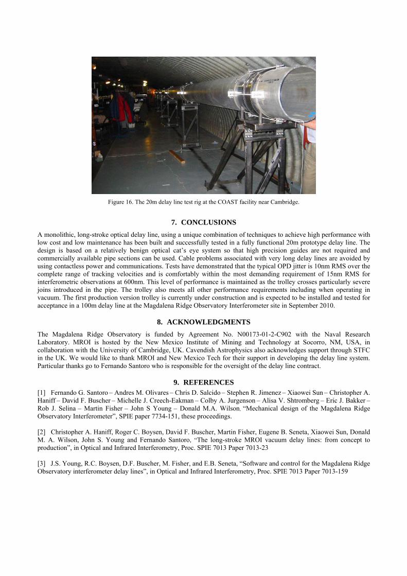
Figure 16. The 20m delay line test rig at the COAST facility near Cambridge.
7. CONCLUSIONS A monolithic, long-stroke optical delay line, using a unique combination of techniques to achieve high performance with low cost and low maintenance has been built and successfully tested in a fully functional 20m prototype delay line. The design is based on a relatively benign optical cat’s eye system so that high precision guides are not required and commercially available pipe sections can be used. Cable problems associated with very long delay lines are avoided by using contactless power and communications. Tests have demonstrated that the typical OPD jitter is 10nm RMS over the complete range of tracking velocities and is comfortably within the most demanding requirement of 15nm RMS for interferometric observations at 600nm. This level of performance is maintained as the trolley crosses particularly severe joins introduced in the pipe. The trolley also meets all other performance requirements including when operating in vacuum. The first production version trolley is currently under construction and is expected to be installed and tested for acceptance in a 100m delay line at the Magdalena Ridge Observatory Interferometer site in September 2010.
8. ACKNOWLEDGMENTS The Magdalena Ridge Observatory is funded by Agreement No. N00173-01-2-C902 with the Naval Research Laboratory. MROI is hosted by the New Mexico Institute of Mining and Technology at Socorro, NM, USA, in collaboration with the University of Cambridge, UK. Cavendish Astrophysics also acknowledges support through STFC in the UK. We would like to thank MROI and New Mexico Tech for their support in developing the delay line system. Particular thanks go to Fernando Santoro who is responsible for the oversight of the delay line contract.
9. REFERENCES [1] Fernando G. Santoro – Andres M. Olivares – Chris D. Salcido – Stephen R. Jimenez – Xiaowei Sun – Christopher A. Haniff – David F. Buscher – Michelle J. Creech-Eakman – Colby A. Jurgenson – Alisa V. Shtromberg – Eric J. Bakker – Rob J. Selina – Martin Fisher – John S Young – Donald M.A. Wilson, “Mechanical design of the Magdalena Ridge Observatory Interferometer”, SPIE paper 7734-151, these proceedings. [2] Christopher A. Haniff, Roger C. Boysen, David F. Buscher, Martin Fisher, Eugene B. Seneta, Xiaowei Sun, Donald M. A. Wilson, John S. Young and Fernando Santoro, “The long-stroke MROI vacuum delay lines: from concept to production”, in Optical and Infrared Interferometry, Proc. SPIE 7013 Paper 7013-23 [3] J.S. Young, R.C. Boysen, D.F. Buscher, M. Fisher, and E.B. Seneta, “Software and control for the Magdalena Ridge Observatory interferometer delay lines”, in Optical and Infrared Interferometry, Proc. SPIE 7013 Paper 7013-159