design of wireless prosthetic hand. introduction why wireless robotic arm system description ...
TRANSCRIPT

DESIGN OF WIRELESS PROSTHETIC HAND

IntroductionWhy Wireless robotic armSystem DescriptionBlock DiagramSystem OperationConclusionReferencesPhotographs
Contents

Introduction
Prosthetic arms which are available in the market are classified as Mechanical Arm Electrical driven arm Myo-electric arm
Mechanical arm operates using body power with the use of Bowden cables. That cable is attached to the soldier with a string. When the movement of the soldier occurs, the cable is stretched hence opening & closing of plum takes place.
Electrically driven arm operates using relays & switches, no harness cable is required.
With the advent of new technology arm prosthesis reached to a new dimension results a new prosthetic arm , where the features of grip force has been implemented & the whole system operates using EMG signal (Signal from muscle)

Why Wireless Robotic arm
It has been seen that the signal strength from amputee stump decreases as the years of amputation increases.
It is because the muscle slowly lost its elasticity, if it is unused for a number of years
For the amputation above 20 years, the muscles permanently lost its elasticity and comes under a permanent fatigue state.
EMG signal lost forever in that situation. So our state-of-the-art technology (Myo Electric arm) will be of no use.
In this situation it is indeed a very challengeable task for rehabilitation.
Amputee needs all types of features like Myo electric arm but the feed signal should not be EMG.
As a solution of the above stated problem, we have developed one wireless robotic arm, in CSIO where all the features are present but the input feed is not an EMG signal, It operates using wireless switch.

System Description
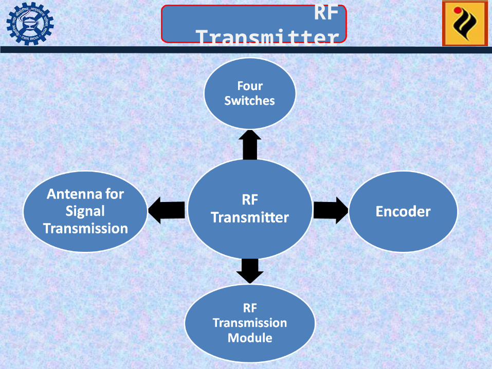
RF Transmitter
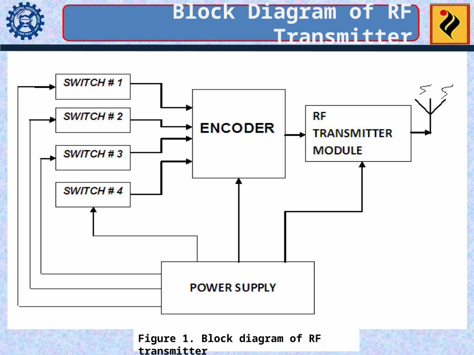
Block Diagram of RF Transmitter
Figure 1. Block diagram of RF transmitter

Contd..
Switches All the switches are of Micro switch type They are connected with four input data pins of Encoder The switches are marked as “STOP”; “OPEN”; “CLOSE WITH LOW GRIP”; “CLOSE WITH HIGH GRIP” (Right to left)
Encoder The encoder has 8 bit address bus, four bit data bus One Transmission enable port pin, denotes whether the transmission is successful or not The address bus is grounded as no another device except switches are connected One internal crystal which provides the clock for data transmission
Contd..
RF Transmission module This module is used for data modulation & transmission The modulation type is AM Carrier frequency is 434 MHz
Antenna for RF communication It is a simple wire It is stripped at another end, which acts as a simple wire radiator antenna
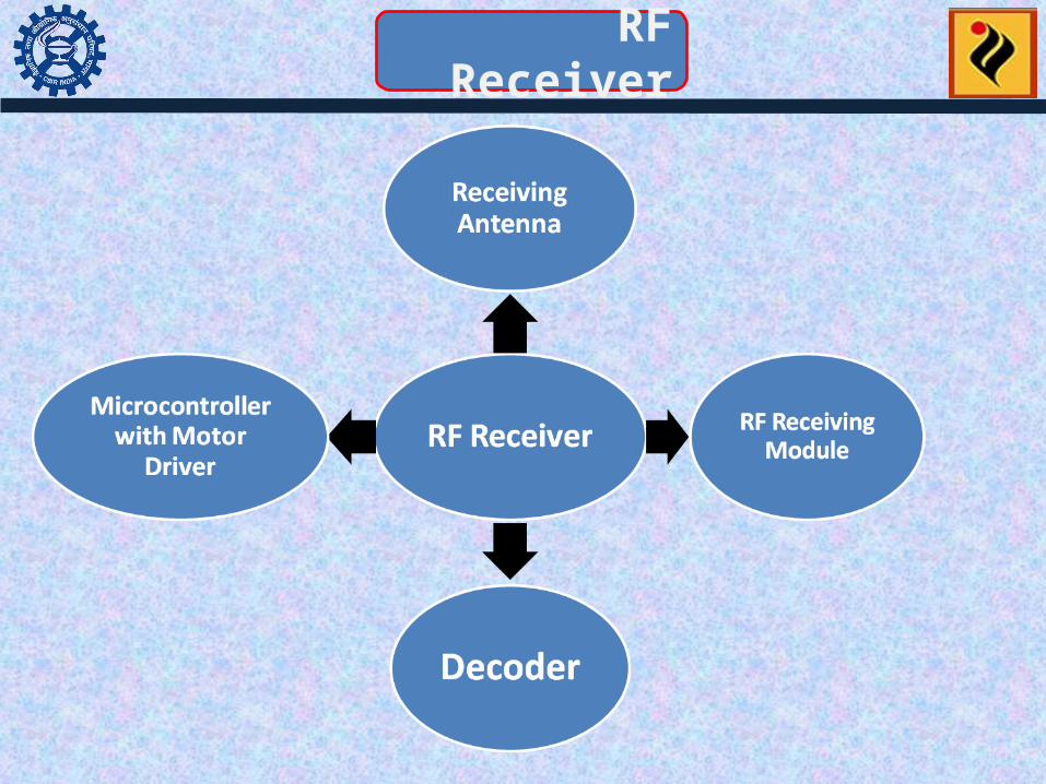
RF Receiver

Block Diagram of RF Receiver
Figure 2. Block diagram of RF receiver with grip controlled circuitry

Contd..
Antenna for RF Receiver It is same as described in Transmitter section
RF Receiving module This module is used for data demodulation & re shaping The Demodulation type is AM Carrier frequency is 434 MHz
Decoder The decoder is synchronized with encoders in all prospect The decoder has same 8 bit address bus, four bit data output. All the data output pins are connected to the microcontroller pins One Valid Transmission port pin, denotes whether the transmission is valid or not The address bus is grounded One internal crystal which provides the clock for data receiving

Contd..
Microcontroller With Motor Driver
It is the heart of the whole system All Four output pins from decoder and the Motor driver pins’ are connected with microcontroller as shown in the block diagram of receiver The two limit switches measures the maximum extent of opening & closing of Plum The Opto Switches are used as a Limit Switch Microcontroller drives the DC motor through Driver circuitry as the signal (Low to High ) received from the Decoder output pins. External Pulse shaping circuit is used to control the duty cycle of the pulses generates to control the speed of DC motor The software written based on speed control of DC motor

System Operation

Contd..
• Video of wireless prosthetic hand

Conclusion
The arm has been developed & Tested with 2 different level of grip forces in CSIO
The wrist is not automatic, it is manually controlled Rachett based.
Level of the grip forces can be increased if the number of the switches are increased in transmitter section.
Wrist rotation can be controlled electronically if the mechanical arrangement can be modified and attached with motor shaft.

Photograph
Figure: Transmitter & Receiver along with Hand

References
[1] Ferguson, G Reg Dunlop, “Grasp Recognition from Myo electric Signal”, Proc. Australasian Conference on Robotics and Automation, 27-29, Nov 2002, Auckland [2] Andres Herrera, Andres Bernal, David Isaza and Malek Adjouadi, “Design of a Electrical Prosthetic Gripper using EMG and Linear Motion Approach”, the National Science Foundation grants EIA- 9906600 and HRD-0317692
[3] Edwin Iversen, Harold H. Sears, and Stephen C. Jacobsen, “APPLICATIONS OF CONTROL”, IEEE Control Systems Magazine, pp 16-20, 2005 (doi: 10.1109/MCS.2005.1388792)

Thank you !